

Page 1
SAVEVTR200/B
UserManual
©2015CopyrightSystemairAB
SystemairABcanacceptnoresponsibilityforpossibleerrorsincatalogues,brochuresandotherprinted
material.SystemairABreservestherighttoalteritsproductswithoutnotice.Thisalsoappliestoproducts
alreadyonorderprovidedthatsuchalterationscanbemadewithoutsubsequentialchangesbeing
necessaryinspecicationsalreadyagreed.
Allrightsreserved.
Documentinoriginallanguage
208062-EN_GB
2015-11-19A003
Page 2
Contents
1Disposalandrecycling...............................................................................................................1
2Warnings...................................................................................................................................1
3Introduction...............................................................................................................................2
4Conguration.............................................................................................................................2
4.1Controlpanel...................................................................................................................2
4.2Settingthetemperature....................................................................................................3
4.3Manualsettingofairow...................................................................................................4
4.4ProgrammingtheWeekschedule......................................................................................5
4.5Manualandautomaticsummermode................................................................................6
5Maintenanceoftheunit..............................................................................................................6
5.1Warnings.........................................................................................................................6
5.2Openthefronthatch.........................................................................................................6
5.3Changinglters................................................................................................................7
5.4Resettingtheltertime.....................................................................................................8
5.5Checkingandcleaningtheheatexchanger........................................................................9
5.6Cleaningthefans.............................................................................................................9
5.7Replacingrotordrivebelt..................................................................................................10
6Overheatprotectionresetbutton.................................................................................................12
7Ductsystemmaintenance..........................................................................................................13
7.1Cleaningextractlouvresandsupplyairdiffusers................................................................13
7.2Checkingtheoutdoorairintake.........................................................................................13
7.3Checkingtheroofcowl(iftted).........................................................................................13
7.4Checkingandcleaningtheductsystem.............................................................................13
8Troubleshooting........................................................................................................................14
8.1Alarmlist..........................................................................................................................14
8.2Typelabel........................................................................................................................15
Page 3

1Disposalandrecycling
ThisproductareapplicabletotheWEEEdirective.Whendisposingtheunit,follow
yourlocalrulesandregulations.
Thisproductpackingmaterialsarerecyclableandcanbereused.Donotdisposein
householdwaste.
2Warnings
Thefollowingadmonitionswillbepresentedindifferentsectionsofthedocument:
Danger
•Makesurethatthemainssupplytotheunitisdisconnectedbeforeperforminganymaintenanceor
electricalwork!
•Allelectricalconnectionsandmaintenanceworkmustbecarriedoutbyanauthorizedinstallerand
inaccordancewithlocalrulesandregulations.
Warning
•Thesystemshouldoperatecontinuously,andonlybestoppedformaintenance/service.
•Theinstallationoftheunitandcompleteventilationsystemmustbeperformedbyanauthorized
installerandinaccordancewithlocalrulesandregulations.
•Bewareofsharpedgesduringmountingandmaintenance.Useprotectivegloves.
•AllthoughtheMainssupplytotheunithasbeendisconnectedthereisstillriskforinjurydueto
rotatingpartsthathavenotcometoacompletestandstill.
•Makesurethatltersaremountedbeforestartingtheunit.
•Thisproductmustonlybeoperatedbyapersonwhichhassuitableknowledgeoreducationwithin
thiseldorcarriedoutwiththesupervisionofasuitablyqualiedperson.
Caution
•Donotconnecttumbledryerstotheventilationsystem.
•Ductconnections/ductendsmustbecoveredduringstorageandinstallation.
SAVEVTR200/BUserManual
208062
1
SystemairSverigeAB
Page 4
3Introduction
TheSAVEVTR200/Bisaheatrecoveryventilationunitwithabuiltinrotatinghighlyefcientheat
exchanger.TheSAVEVTR200/Bissuitableforsmalleratsorhouses.Itsupplieslteredoutdoorairto
residentialareasandextractairfrombathroom,kitchenandwetrooms.
Therearetwomodeloptions,right(R)andleft(L)model.Bothmodelscomewith500Wor1000W
installedre-heaterbattery .Thedifferentmodelsarerecognizedbytheplacingoftheinternalcomponents.
Thismanualdescribesbasicinformationhowtooperateandperformmaintenanceonaleft(L)unitand
thesystemitisconnectedto.
Note:
Thisdocumentdescribesaleft(L)model.Theinsideofaright(R)modelismirrored.
4Conguration
4.1Controlpanel
Connecttheunitelectricallytothemainswiththeenclosedplugandcheckthatitstartsupcorrectly.
Thecontrolpanelisusedtomakethenecessaryadjustments.
Anexternalcontrolpanelcanbeconnectedonthetopoftheunit.
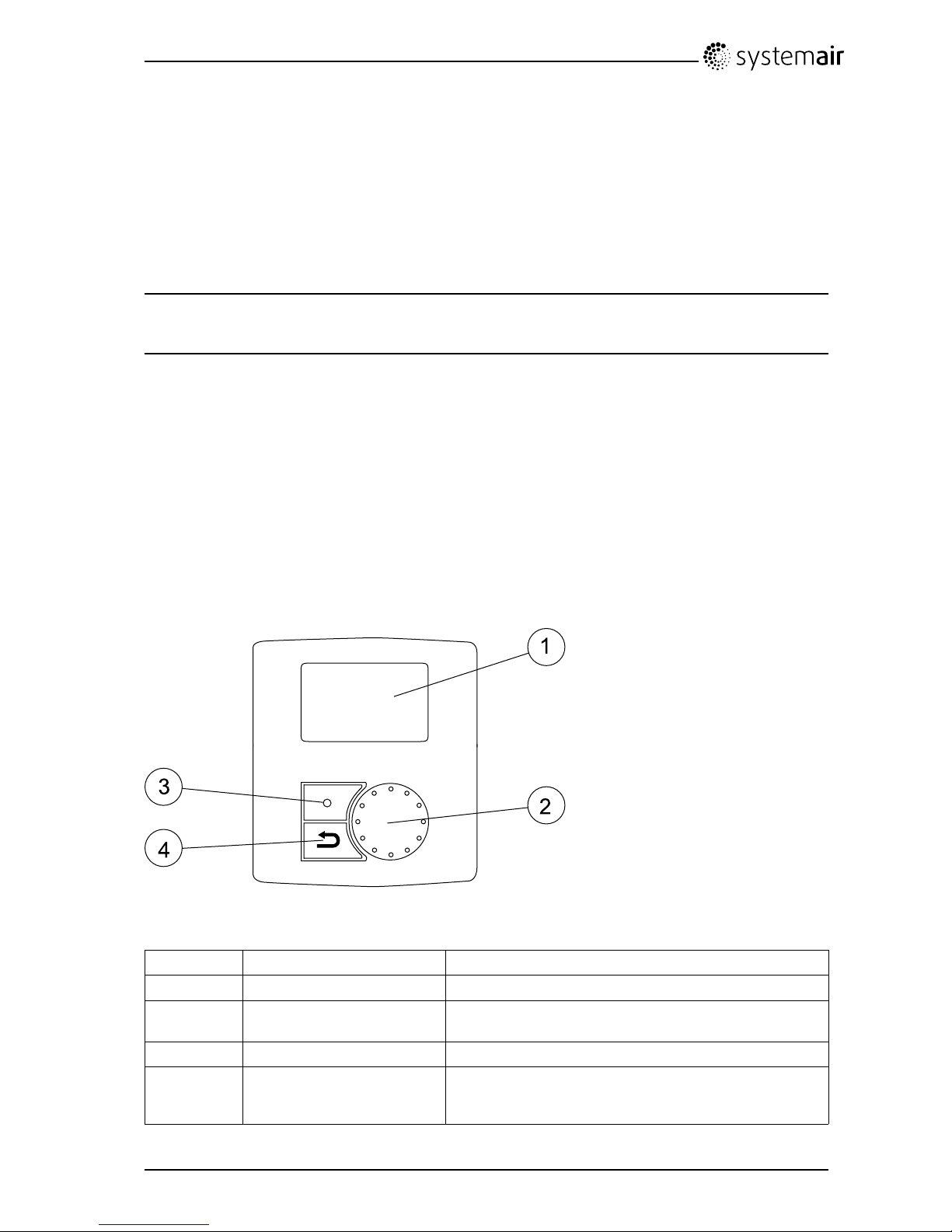
Theillustrationbelowshowsthecontrolpanelwithashortdescription.
Fig.1Controlpanel
PositionDescriptionExplanation
1Display
Showssymbols,menusandsettings
2
SELECTIONknob
Movethroughthemenulistsorchangesettingsand
valuesbyturningtheknobleftorright
3ENTERbuttonENTERmenuchoicesorsettingsbypressingthebutton
4RETURNbutton
StepRETURNinthemenulevelsandtoabortaninitiated
parameterchangeandrestoretheoriginalvalueby
pressingthebutton
SAVEVTR200/BUserManual
208062
2
SystemairSverigeAB
Page 5
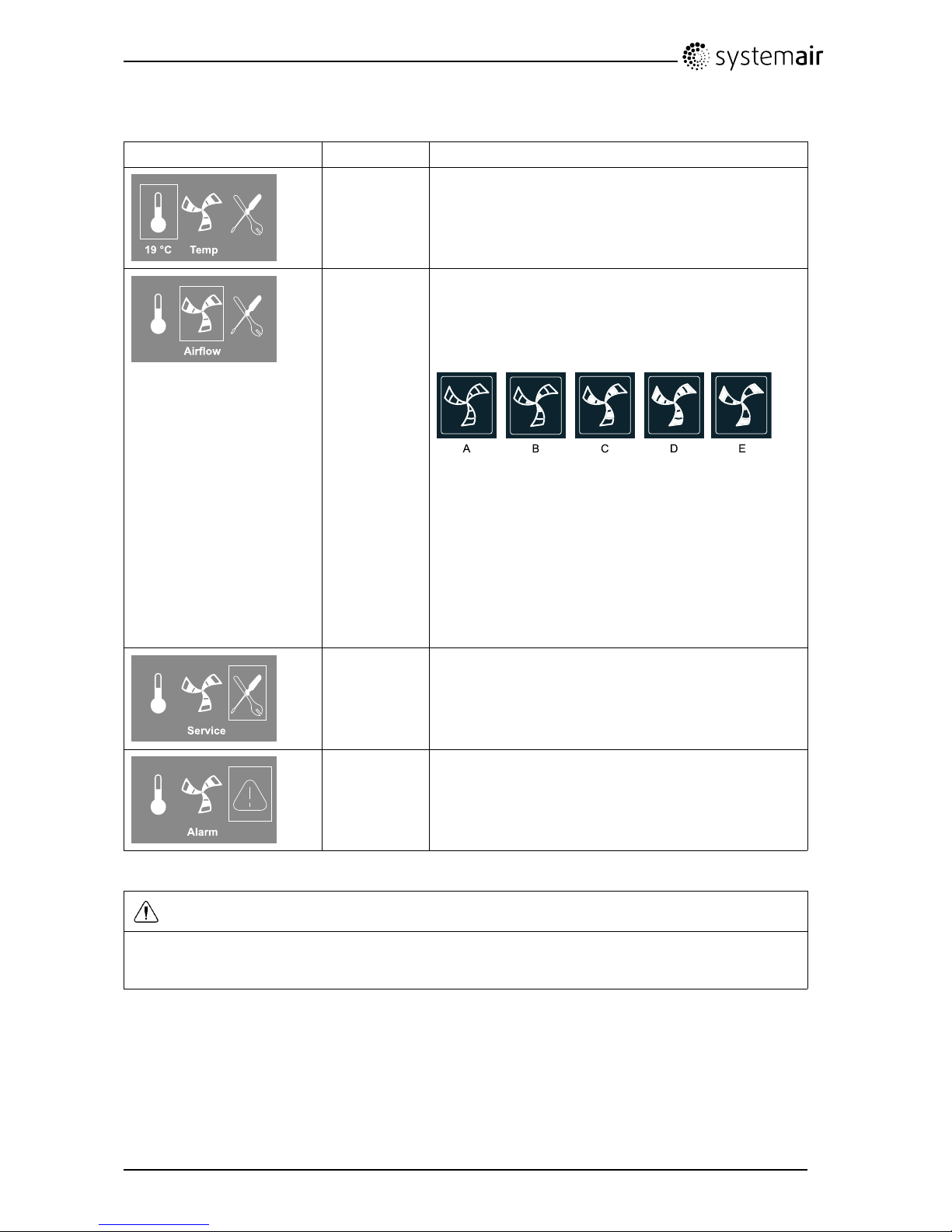
4.1.1Displaysymbols
Symbol
DescriptionExplanation
Temp
Illustratesthecurrentset-pointforsupplyairtemperature
(fromcompletelyemptytolledsymbol).
TurntheSELECTIONknobtochoosetemperature.
PressENTERtosavethesetting.
AirowIllustratesthecurrentairow.Theairowcanbeset
manuallyin5steps:Off,Low,Nom,HighandAuto.
TurntheSELECTIONknobtochooseairow.
PressENTERtosavethesetting.
A.Ventilationoff.
1
B.Lowventilation:Canbeusedwhenleavingthe
buildingforalongerperiod
C.Nominalventilation:Willgiverequiredairchange
undernormalconditions.
D.Maximumventilation:T oincreasetheairowif
necessary.
E.Autoventilation:Willregulateafterthepre-settingfor
thedemandcontrolsettings.
Service
PressENTERtoaccesstheservicemenu.
AlarmPressENTERtoaccessthealarmlist.
1.ThefancanbesettoOFFbyactivatingmanualfanstop.Seeservicemenudescriptionunderfunctions.
Important
Itisnotrecommendedtoactivatemanualfanstop(setfantoOFF)instandardhouseholds.Ifmanualfan
stopisactivated,theunitshouldbeprovidedwithdampersinexhaustandfreshairductstoavoidcold
draughtandriskofcondensationwhentheunithasbeenstopped.
4.2Settingthetemperature
Thesupplyairtemperatureissetmanuallyinstepsof1Kinthemainmenudisplaybychoosingthe
temperaturesymbol.
Ifanelectricalre-heaterisinstalledthetemperaturesetpointsare:
12-22°C.Forinstalledwaterre-heaterthesetpointsare:12-40°C.
SAVEVTR200/BUserManual
208062
3
SystemairSverigeAB
Page 6
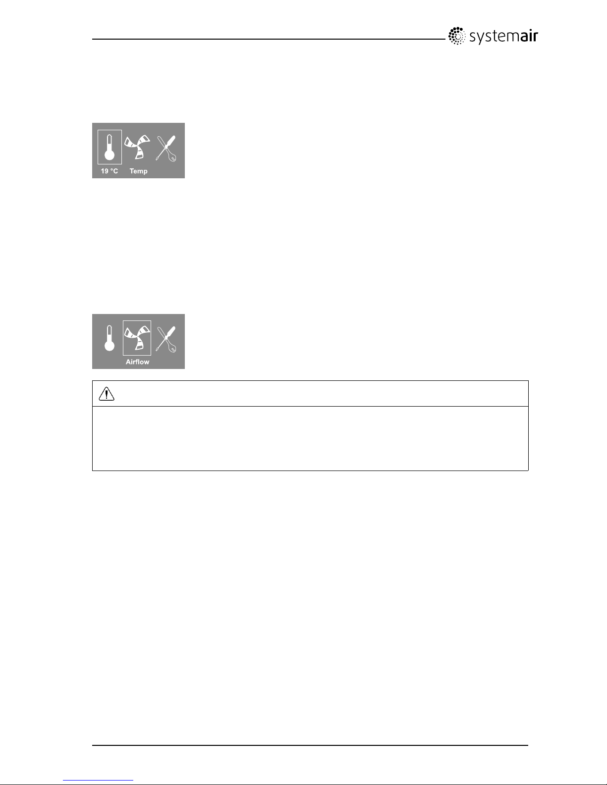
Ifthere-heaterisdeactivated,thetemperaturestepsare:
15-19°C.Defaultvalue:15.0°C.
Eachtemperaturestepisillustratedbyincreasingthellingofthetemperaturesymbolandthetemperature
isshowninthedisplay
Anunlledtemperaturesymbolwillactivatemanualsummermode.Seechapter4.5
4.3Manualsettingofairow
Itispossible,atanytime,tomanuallysettheairowinthemainmenudisplay.Bychoosingthefansymbol
andconrming,itispossibletoincreaseordecreasetheairowin5steps:Off,Low,Nom,HighandAuto.
Bydoingso,youoverridetheprogrammedweekschedulefortheunituntiltheendofthepresenttime
periodintheweekprogram(chapter4.4).
Warning
Itisnotrecommendedtoactivatemanualfanstop(setfantoOFF)instandardhouseholds.Ifmanual
fanstopisactivated,theunitshouldbeprovidedwithdampersinexhaustandfreshairductstoavoid
colddraughtandriskofcondensationwhentheunithasbeenstopped.
ThefancanbesettoOFFbyactivatingmanualfanstop.SeetheInstallationandServicemanual,
chapterServicemenuoverview:Manualfanstop.
SAVEVTR200/BUserManual
208062
4
SystemairSverigeAB
Page 7

4.4ProgrammingtheWeekschedule
Settheweekscheduleaccordingtobelowprocedure:
1.Gototheservicemenubyusingthe
SELECTIONknob.
2.Entertheservicelevelbytypingthepassword,
default1111.UsetheSELECTIONknobforeach
digitandconrmwiththeENTERbuttonaftereach
setdigitandchoose"NO"forthesystemnotbe
locked.
Password
PasswordXXXX
LockedYES/NO
3.Goto:Weekprogram
Service
Weekprogram
4.ChooseWeekprogramagain.
Weekprogram
Airflow
5.Setweekdayandtimeyouwanttheunitto
beinONlevel.Twoperiodsperdaycanbe
programmed.Therestofthetimetheunitwillbein
OFFlevel.
Weekprogram
Day:MON
Per1:07:0016:00
Per2:00:0000:00
6.Gobacktothepreviousdialogueframewiththe
RETURNbuttonandgodowntoAirflow.
Weekprogram
Airflow
7.Setwhichairowthefanissupposedtobe
runningintheONlevel,choosebetweenLow,
Nom,HighorAuto.
Setwhichairowthefanissupposedtoberunning
intheOFFlevel,choosebetweenOFF,Low,Nom
orHigh.
Note:
Ifanelectricalre-heaterbatteryisinstalledand
activeandtheunitisshutdownfromthecontrol
panel,forexamplebychoosingOFF.Whenthe
unitisinOFFlevelintheweekprogram,thefans
willcontinuetorunfor3minutes,topreventthe
heaterfromtriggeringtheoverheatprotection
sensor,beforetheystop.
Airflow
Onlevel:low/nom/high/auto
Offlevel:off/low/nom/high
8.StepbackwiththeRETURNbuttonuntilyou
reachthemainmenudisplay
SAVEVTR200/BUserManual
208062
5
SystemairSverigeAB
Page 8

4.5Manualandautomaticsummermode
Manualsummermodeoccursifnotemperaturestepisselected.Thetemperaturesymbolonthemain
menuisthencompletelyempty .
Iftheelectricalre-heaterisactivated,itwillswitchoffduringmanualsummermode.Manualsummer
modegoesautomaticallytostep1(setpoint12°C)aftertwominutesifthesupplyairtemperatureis
+5°Corbelow.
Ifawaterheaterbatteryisinstalledandactivated,themanualsummermodegoesautomaticallytostep1
(setpoint12°C)iftheoutdoorairorsupplyairtemperatureis+5°Corbelow.
Theunitwillautomaticallyalternatebetweenwinteroperationwithheatrecoveryandsummeroperation
withoutheatrecovery .
5Maintenanceoftheunit
MaintenanceoftheSAVEVTR200/Bshouldnormallybeperformed3-4timesayear.
5.1Warnings
Danger
•Makesurethatthemainssupplytotheunitisdisconnectedbeforeperforminganymaintenanceor
electricalwork!
•Allelectricalconnectionsandmaintenanceworkmustbecarriedoutbyanauthorizedinstallerand
inaccordancewithlocalrulesandregulations.
Warning
•Thesystemshouldoperatecontinuously,andonlybestoppedformaintenance/service
•Althoughthemainssupplytotheunithasbeendisconnectedthereisstillriskforinjuryduetorotating
partsthathavenotcometoacompletestandstill
•Bewareofsharpedgesduringmaintenance.Useprotectivegloves
•Makesurethatltersaremountedintheirplacebeforerunningthesystem
•Thisproductmustonlybeoperatedbyapersonwhichhassuitableknowledgeoreducationwithin
thiseldorcarriedoutwiththesupervisionofasuitablyqualiedperson.
5.2Openthefronthatch
Openthehatchwiththetwolatchesandswingthehatchopen.
SAVEVTR200/BUserManual
208062
6
SystemairSverigeAB
Page 9

5.3Changinglters
Theltersaretobechangedevery6/9/12/15months,defaultvalueis12months.Whentheltershave
beenchangedtheltertimermustberesetseechapter5.4
ThefactoryinstalledltersareoflterqualityF7forthesupplyairandG3fortheextractairlter.Thelters
needtobereplacedwhenpolluted.Newsetsoflterscanbeacquiredfromyourinstallerorwholesaler.
1
Toremovethesupplyairlterloosentheknobsto
removethelterlock(imageshowswhenlteris
hidden).Onlyoneofthelterlocksneedstobe
removed.
2
Wigglethelterandpullitout.
3
Toremovetheextractairlter,loosentheknobs
andpullthelterlock.Thentheltercanbe
removed.
FilterqualityG3canbeinstalledforsupplyairltering.
Theltertypeislabelledonthetopofthelter.
Caution
IftypeG3ltersareusedinsteadofF7,thesystemcurveforSupplyFan(SF)mustbechanged:
ForG3typelter:11–20,forF7typelter:1–10.See“VTR200InstallationandService”
SAVEVTR200/BUserManual
208062
7
SystemairSverigeAB
Page 10

5.4Resettingtheltertime
1.Gototheservicemenubyusingtheselection
knob.
2.Entertheservicelevelbytypingthepassword.
UsetheSELECTIONknobforeachdigitand
conrmwiththeENTERbuttonaftereachsetdigit
andchoose"NO"forthesystemnotbelocked.
Service
—>Password
LockedYES/NO
3.Goto:Filterperiod,pressENTER.
Choose:Reset:YESwiththeSELECTION
knobandthenENTER.
Change,ifnecessary ,Timetoreplace
Xmonth,tothetimeofyourchoicewiththe
SELECTIONknobandthenpressENTER.
PresstheRETURNbuttonuntilyoureachthemain
menu.
Filterperiod
Timetoreplace:6/9/12/15month
ResetNO/YES
SAVEVTR200/BUserManual
208062
8
SystemairSverigeAB
Page 11

5.5Checkingandcleaningtheheatexchanger
Danger
•MakesurethattheMainssupplytotheunitisdisconnectedbeforeperforminganymaintenanceor
electricalwork!
Eveniftherequiredmaintenanceiscarriedout,dustwillbuildupintheexchangerblock.Itisthereforeof
vitalimportancefortheupkeepofahighefciencythattheexchangerblockisremovedfromtheunitand
cleanedperiodicallyasillustratedbelow.Cleantheheatexchangeratleastevery3yearsorwhenrequired.
1.Disconnecttherotorpowersupplyandtherotorsensor.Thecablesarefoundbesidetherotoratthe
back.
2.Pullouttherotortowardsyou.Someforcemaybeneeded.
3.Cleantherotor.
Washinhotsoapywater.Donotusedetergentcontainingammonia.Rinseusing,forinstance,a
showerhandleorcarefullywithcompressedair.
Warning
Ensuretherotormotorisnotexposedtomoisture
4.Remounttherotor.Don’tforgettoreconnecttherotorpowerandsensorcables.
Fig.2Heatexchanger
5.6Cleaningthefans
Danger
•MakesurethattheMainssupplytotheunitisdisconnectedbeforeperforminganymaintenanceor
electricalwork!
Themotorbearingsarelifetimelubricatedandmaintenancefree.
Eveniftherequiredmaintenance,suchaschangingofltersiscarriedout,dustandgreasemayslowly
buildupinsidethefans.Thiswillreducetheefciency.
SAVEVTR200/BUserManual
208062
9
SystemairSverigeAB
Page 12

Thefansmaybecleanedasillustratedinbelowprocedure.
1.Disconnectthefanpowercables.Thecablesarefoundbesidethefanattheback.
2.Pulloutthefanstowardsyou.Someforcemaybeneeded.
3.Cleanthefanswithaclothorasoftbrush.Donotusewater.Whitespiritcanbeusedtoremove
obstinatedeposits.
Allowthefanstodryproperlybeforeremounting.
4.Remountthefans.Don’tforgettoreconnectthefanpowercables.
Fig.3Extractandsupplyairfans
5.7Replacingrotordrivebelt
Note:
Dependingonmodel,leftorright,itmaybenecessarytoremovetheheatexchangerinordertoreplacea
brokendrivebeltsincethebeltpulleycannotbeaccessed.
Iftherotormotorisplacedatthebackoftheunit,itisrecommendedtoremovetheheatexchangerto
changethedrivebelt,seechapter5.7.2.
IfthealarmRotorisraised,seechapter8.1,therotordrivebeltmaybedamagedorbroken.
Thereplacementdrivebelt(1)isadjustableanddeliveredwithanippleattachedinoneend.
Danger
•MakesurethattheMainssupplytotheunitisdisconnectedbeforeperforminganymaintenanceor
electricalwork!
Warning
Riskofpersonalinjury!Theheatexchangerweighsabout14kg.Thereisariskthattheheatexchanger
fallsoutoftheunit.
Makesurethatsmallchildrenarenotbeneaththeunitwhentheheatexchangerisremoved!
SAVEVTR200/BUserManual
208062
10
SystemairSverigeAB
Page 13

Fig.4Rotordrivebelt
5.7.1Heatexchangermounted
1.Stoptheunitbydisconnectingthemains.
2.Openthefronthatch.
3.Removethebrokendrivebelt.
4.Usetapetoattachthedrivebelttotherotatingheatexchanger,androtatetheexchangerbyhand
togetholdofthedrivebelt.
5.Removethetapeandputthe”empty”endontothenipple.
6.Pressthedrive-beltendsrmlytowardseachothertosecurethenipple.
7.Pullthedrivebeltontothebeltpulleyandrotatetheexchangerbyhand.Checkthatthebeltpulley
rotates.
Note:
Ifthedrivebeltslips,thedrivebeltmaybetoolongandneedstobeshortened.Cutthedrivebelt5
mmandgotostep6.
8.Closeandlockthefronthatchandconnecttheunittomains.
9.CheckthatthealarmhasceasedontheControlDisplay.
Note:
Ifthealarmremains,checktherotorsensor.
SAVEVTR200/BUserManual
208062
11
SystemairSverigeAB
Page 14

5.7.2Heatexchangerremoved
1.Stoptheunitbydisconnectingthemains.
2.Openthefronthatch.
3.Disconnecttheheatexchangerpowersupplyandtherotorsensor.Thecablesarefoundbesidethe
heatexchangerattheback.
4.Pullouttheheatexchangertowardsyou.Someforcemaybeneeded.
5.Removethebrokendrivebelt.
6.Applythenewdrivebeltaroundtheheatexchanger.
7.Pressthedrive-beltendsrmlytowardseachothertosecurethenipple.
8.Pullthedrivebeltontothebeltpulleyandrotatetheexchangerbyhand.Checkthatthebeltpulley
rotates.
Note:
Ifthedrivebeltslips,thedrivebeltmaybetoolongandneedstobeshortened.Cutthedrivebelt5
mmandgotostep7.
9.Mounttheheatexchanger.Don’tforgettoreconnecttherotorpowerandsensorcables.
10.Closethefronthatchandconnecttheunittomains.
11.CheckthatthealarmhasceasedontheControlDisplay .
Note:
Ifthealarmremains,checktherotorsensor.
6Overheatprotectionresetbutton
Ifthesupplyairtemperatureislow,itcanindicatethattheoverheatprotectionistriggered.Theoverheat
protectioncanberesetbypressingtheresetbutton(1).
Fig.5Overheatprotectionresetbutton
SAVEVTR200/BUserManual
208062
12
SystemairSverigeAB
Page 15

7Ductsystemmaintenance
7.1Cleaningextractlouvresandsupplyairdiffusers
Thesystemsuppliesfreshairtoyourhomeandextractstheusedindoorairviatheductsystemand
diffusers/louvres.Diffusersandlouvresaremountedinceilings/wallsinbedrooms,livingroom,wetrooms,
WCetc.Removediffusersandlouvresandwashinhotsoapywaterasrequired(diffusers/louvresmust
notbeexchanged).Cleaningofdiffusers/louvrescanbedoneasnecessary.
Fig.6Diffusersandlouvres
7.2Checkingtheoutdoorairintake
Leavesandpollutioncouldpluguptheairintakegrilleandreducethecapacity.Checktheairintakegrille,
andcleanasnecessary .Itisrecommendedtodothisatleasttwiceayear.
Fig.7Intakegrill
7.3Checkingtheroofcowl(iftted)
Theroofcowl(iftted)connectedtotheexhaustairductneedstobecheckedatleasttwiceayearand
cleanedifnecessary .
7.4Checkingandcleaningtheductsystem
Dustandgreasedepositsmaybuildupintheductsystem,evenifrequiredmaintenancesuchaschanging
ofltersisbeingcarriedout.Thiswillreducetheefciencyoftheinstallation.
Theductrunsshouldthereforebecleaned/changedwhennecessary .Steelductscanbecleaned
bypullingabrushsoakedinhotsoapywaterthroughtheductviadiffuser/louvreopeningsorspecial
inspectionhatchesintheductsystem(iftted).
Itisrecommendedtodothisevery5yearsandisnormallycarriedoutbyauthorizedcompanies
specializedinthisarea.
SAVEVTR200/BUserManual
208062
13
SystemairSverigeAB
Page 16

Fig.8Cleaningductsystem
8Troubleshooting
Awarningtrianglewithtextinthedisplayindicatesanalarm.Turnmenuselectortothewarningtriangle
andpressconrmtwicetoviewthealarm.
8.1Alarmlist
AlarmExplanation
Dothefollowing
Fan
Indicateserroroneithersupplyor
extractairfan.
Thealarmisdisplayedinthecontrolpanel.
Checkthatquickconnectorsareconnectedforthe
bothfans.
Contactyourinstallationcompanyorplaceof
purchase.
EMT/Frost
Indicatestriggeredfrostprotection
(incaseofinstalledwaterheating
battery)ortriggeredoverheat
protection(incaseofinstalled
electricre-heaterbattery).
Atriggeredfrostprotectionalarmresultsinthe
following:
•Bothfansstop.
•Outdoorandexhaustairdampersclosed.
•Watervalveopenscompletely(10Vsignalgoes
outtotheactuator).
Theunitwillrestartoncethewatertemperature
reaches+5°Cabovethesetfrostprotection
temperature.
Atriggeredoverheatprotection(EMT)givesanalarm
inthecontrolpanel.
Resetbypushingtheresetbutton.Seechapter6.
Iftheproblemcontinuescontactyourinstallation
companyorplaceofpurchase.
SAVEVTR200/BUserManual
208062
14
SystemairSverigeAB
Page 17

AlarmExplanation
Dothefollowing
Rot
Indicatesarotormalfunction.
Thealarmisdisplayedinthecontrolpanel.
•Iftherotatingheatexchangerhasstopped.Check
therotorbelt.Seechapter5.7
•Iftheheatexchangerisstillrotating,checkthatthe
quickconnectorforthesensorisconnectedand
thatthereisanairgapof5-10mmbetweenthe
sensorandthemagnet.
Adjustthegapifnecessary.
Ifthealarmpersists,therotorsensormaybefaulty.
Contactyourinstallationcompanyorplaceof
purchase.
PbFail
Errorinconnectionwithrelay
cardfortheelectricalre-heater(if
installedandactivated).
Theoverheatprotectionsensor,
automaticreset(ET2)maybe
triggeredduetohightemperature.
Thealarmisdisplayedinthecontrolpanel.
Theheaterwillnotbeactivated.
FortriggeredET2,wait10–15min.Iftheerror
remains,contactyourinstallationcompanyorplace
ofpurchase.
Temp
Malfunctioninoneormoreofthe
temperaturesensors.
Thealarmisdisplayedinthecontrolpanel.
Contactyourinstallationcompanyorplaceof
purchase.
Filter
Timeforlterchange.
Thealarmisdisplayedinthecontrolpanel.
ChangelteraccordingtotheinstructionsintheUser
Manual.
LowSS
Indicateslowsupplyair
temperature
Thealarmisdisplayedinthecontrolpanel.
Ifwaterreheaterisconguredandfrostprotection
havefailed,thenanextrasecurityfunctionistriggered
whensupplyairtemperatureislowerthan5°Cand
outdoorairtemperatureisbelow0°C.
RH
Indicatesmalfunctionofinternal
relativehumiditysensor.
Thealarmisdisplayedinthecontrolpanel.
8.2Typelabel
Beforecallingyourservicerepresentative,makeanoteofthespecicationandproductionnumberfrom
thetypelabel,whichcanbefoundonthesideoftheunits,nexttotheexternalconnections.
SAVEVTR200/BUserManual
208062
15
SystemairSverigeAB
Page 18

Fig.9T ypelabel
PositionDescription
1
Productcode(productspecication)
2Productitemnumber
3Productionordernumber
4
Serialnumber
5
Productiondate(YY .MM.DD)
SAVEVTR200/BUserManual
208062
16
SystemairSverigeAB
Page 19

lastpage
SystemairSverigeABreservestherighttomakechangesandimprovementstothe
contentsofthismanualwithoutpriornotice.
SystemairUAB
Linųst.101
LT–20174Ukmergė,LITHUANIA
Phone +370 340 60165
Fax +370 340 60166
 Loading...