

Page 1

SAVEVTR150/K
0
0
0
0
0
UserManual
©2014CopyrightSystemairAB
SystemairABcanacceptnoresponsibilityforpossibleerrorsincatalogues,brochuresandotherprinted
material.SystemairABreservestherighttoalteritsproductswithoutnotice.Thisalsoappliestoproducts
alreadyonorderprovidedthatsuchalterationscanbemadewithoutsubsequentialchangesbeing
necessaryinspecicationsalreadyagreed.
Allrightsreserved.
Documentinoriginallanguage
207997-EN_GB
20-10-2014A002
Page 2

Contents
1Warnings...................................................................................................................................1
2Introduction...............................................................................................................................1
3Cookerhood..............................................................................................................................2
4Conguration.............................................................................................................................3
4.1Controlpanel...................................................................................................................3
4.1.1Displaysymbols......................................................................................................4
4.2Settingthetemperature....................................................................................................4
4.3Manualsettingofairow...................................................................................................5
4.4ProgrammingtheWeekschedule......................................................................................6
4.5Manualandautomaticsummermode................................................................................7
5Cookerhoodmaintenance..........................................................................................................7
5.1Cleaningcookerhood.......................................................................................................7
5.2Changinghalogenlamps..................................................................................................8
6Maintenanceoftheunit..............................................................................................................8
6.1Warnings.........................................................................................................................8
6.2Remove/mounttheouterfront...........................................................................................9
6.3Remove/mounttheinnerfront...........................................................................................9
6.4Changinglters................................................................................................................10
6.5Resettingtheltertime.....................................................................................................11
6.6Checkingandcleaningtheheatexchanger........................................................................11
6.7Cleaningthefans.............................................................................................................12
6.8Replacingrotordrivebelt..................................................................................................13
6.9Overheatprotectionresetbutton.......................................................................................14
7Ductsystemmaintenance..........................................................................................................14
7.1Cleaningextractlouvresandsupplyairdiffusers................................................................14
7.2Checkingtheoutdoorairintake.........................................................................................15
7.3Checkingtheroofcowl(iftted).........................................................................................15
7.4Checkingandcleaningtheductsystem.............................................................................15
8Troubleshooting........................................................................................................................15
8.1Alarmlist..........................................................................................................................16
8.2Typelabel........................................................................................................................17
Page 3

1Warnings
Thefollowingadmonitionswillbepresentedindifferentsectionsofthedocument:
Danger
•Makesurethatthemainssupplytotheunitisdisconnectedbeforeperforminganymaintenanceor
electricalwork!
•Allelectricalconnectionsandmaintenanceworkmustbecarriedoutbyanauthorizedinstallerand
inaccordancewithlocalrulesandregulations.
Warning
•Thesystemshouldoperatecontinuously,andonlybestoppedformaintenance/service.
•Theinstallationoftheunitandcompleteventilationsystemmustbeperformedbyanauthorized
installerandinaccordancewithlocalrulesandregulations.
•Bewareofsharpedgesduringmountingandmaintenance.Useprotectivegloves.
•AllthoughtheMainssupplytotheunithasbeendisconnectedthereisstillriskforinjurydueto
rotatingpartsthathavenotcometoacompletestandstill.
•Makesurethatltersaremountedbeforestartingtheunit.
•Thisproductmustonlybeoperatedbyapersonwhichhassuitableknowledgeoreducationwithin
thiseldorcarriedoutwiththesupervisionofasuitablyqualiedperson.
Caution
•Donotconnecttumbledryerstotheventilationsystem.
•Ductconnections/ductendsmustbecoveredduringstorageandinstallation.
2Introduction
TheSAVEVTR150/Kisaheatrecoveryventilationunitwithabuiltinrotatinghighlyefcientheat
exchangerandcookerhood.TheSAVEVTR150/Kissuitableforsmalleratsorhouses.Itsupplies
lteredoutdoorairtoresidentialareasandextractairfrombathroom,kitchenandwetrooms.
Therearetwomodeloptions,right(R)andleft(L)model.Bothmodelscomewith500Wor1000W
installedre-heaterbattery .Thedifferentmodelsarerecognizedbytheplacingoftheinternalcomponents.
Thismanualdescribesbasicinformationhowtooperateandperformmaintenanceonaleft(L)unitand
thesystemitisconnectedto.
Note:
Thisdocumentdescribesaleft(L)model.Theinsideofaright(R)modelismirrored.
SAVEVTR150/KUserManual
207997
1
SystemairAB
Page 4

3Cookerhood
Danger
•DoNOTambébeneaththecookerhoodwheninuse.
•Sufcientairowmustbesecuredtotheroomwhenthecookerhoodisinuse
PressbuttonAtoturnonthelights.
PressbuttonBoncetoopentheventilationdamperwhencooking.TheLEDindicator(C)issteadilylit.
PressbuttonBagaintoforcetheventilation.TheLEDindicatorisblinking.
PressbuttonBathirdtimetoclosetheventilationdamper.Theventilationfangoesbacktonominal
speedandtheLEDindicatorgoesoff.
Thedamperwillautomaticallycloseafter60minutesunlessitismanuallyclosed.
Noextractairwillgothroughthecookerhoodin"off"mode.Extractairfromthekitchenneedsaseparate
airvalve.
A B C
Fig.1Cookerhoodfrontpanel
Hint:Letthedamperbeopenawhilebeforeandaftercookingtopreventsmokefromspreadingin
theroom.
SAVEVTR150/KUserManual
207997
2
SystemairAB
Page 5

4Conguration
4.1Controlpanel
Connecttheunitelectricallytothemainswiththeenclosedplugandcheckthatitstartsupcorrectly.
Thecontrolpanelisusedtomakethenecessaryadjustments.
Anexternalcontrolpanelcanbeconnectedonthetopoftheunit.
Theillustrationbelowshowsthecontrolpanelwithashortdescription.
1
2
3
4
Fig.2Controlpanel
PositionDescriptionExplanation
1Display
Showssymbols,menusandsettings
2
SELECTIONknob
Movethroughthemenulistsorchangesettingsand
valuesbyturningtheknobleftorright
3ENTERbuttonENTERmenuchoicesorsettingsbypressingthebutton
4RETURNbutton
StepRETURNinthemenulevelsandtoabortaninitiated
parameterchangeandrestoretheoriginalvalueby
pressingthebutton
SAVEVTR150/KUserManual
207997
3
SystemairAB
Page 6

4.1.1Displaysymbols
Symbol
DescriptionExplanation
Tem p19 °C
Temp
Illustratesthecurrentset-pointforsupplyairtemperature
(fromcompletelyemptytolledsymbol).
TurntheSELECTIONknobtochoosetemperature.
PressENTERtosavethesetting.
Airflow
AirowIllustratesthecurrentairow.Theairowcanbeset
manuallyin5steps:Off,Low,Nom,HighandAuto.
TurntheSELECTIONknobtochooseairow.
PressENTERtosavethesetting.
A.Ventilationoff.
1
B.Lowventilation:Canbeusedwhenleavingthe
buildingforalongerperiod
C.Nominalventilation:Willgiverequiredairchange
undernormalconditions.
D.Maximumventilation:T oincreasetheairowif
necessary.
E.Whendemandcontrolisactivated,fansshouldgoto
"automode"andregulateafterthepre-settingforthe
demandcontrolsettings.
Service
Service
PressENTERtoaccesstheservicemenu.
Alarm
AlarmPressENTERtoaccessthealarmlist.
1.ThefancanbesettoOFFbyactivatingmanualfanstop.Seeservicemenudescriptionunderfunctions.
Warning
Itisnotrecommendedtoactivatemanualfanstop(setfantoOFF)instandardhouseholds.Ifmanualfan
stopisactivated,theunitshouldbeprovidedwithdampersinexhaustandfreshairductstoavoidcold
draughtandriskofcondensationwhentheunithasbeenstopped.
4.2Settingthetemperature
Thesupplyairtemperatureissetmanuallyinstepsof1Kinthemainmenudisplaybychoosingthe
temperaturesymbol.
SAVEVTR150/KUserManual
207997
4
SystemairAB
Page 7

Ifanelectricalre-heaterisinstalledthetemperaturesetpointsare:
12-22°C.Forinstalledwaterre-heaterthesetpointsare:12-40°C.
Ifthere-heaterisdeactivated,thetemperaturestepsare:
15-19°C.Defaultvalue:15.0°C.
Eachtemperaturestepisillustratedbyincreasingthellingofthetemperaturesymbolandthetemperature
isshowninthedisplay
Tem p19 °C
Anunlledtemperaturesymbolwillactivatemanualsummermode.Seechapter4.5
4.3Manualsettingofairow
Itispossible,atanytime,tomanuallysettheairowinthemainmenudisplay.Bychoosingthefansymbol
andconrming,itispossibletoincreaseordecreasetheairowin5steps:Off,Low,Nom,HighandAuto.
Bydoingso,youoverridetheprogrammedweekschedulefortheunituntiltheendofthepresenttime
periodintheweekprogram(chapter4.4).
Airflow
Warning
Itisnotrecommendedtoactivatemanualfanstop(setfantoOFF)instandardhouseholds.Ifmanual
fanstopisactivated,theunitshouldbeprovidedwithdampersinexhaustandfreshairductstoavoid
colddraughtandriskofcondensationwhentheunithasbeenstopped.
ThefancanbesettoOFFbyactivatingmanualfanstop.SeetheInstallationandServicemanual,
chapterServicemenuoverview:Manualfanstop.
SAVEVTR150/KUserManual
207997
5
SystemairAB
Page 8

4.4ProgrammingtheWeekschedule
Settheweekscheduleaccordingtobelowprocedure:
1.Gototheservicemenubyusingthe
SELECTIONknob.
Service
2.Entertheservicelevelbytypingthepassword,
default1111.UsetheSELECTIONknobforeach
digitandconrmwiththeENTERbuttonaftereach
setdigitandchoose"NO"forthesystemnotbe
locked.
Password
PasswordXXXX
LockedYES/NO
3.Goto:Weekprogram
Service
Weekprogram
4.ChooseWeekprogramagain.
Weekprogram
Airflow
5.Setweekdayandtimeyouwanttheunitto
beinONlevel.Twoperiodsperdaycanbe
programmed.Therestofthetimetheunitwillbein
OFFlevel.
Weekprogram
Day:MON
Per1:07:0016:00
Per2:00:0000:00
6.Gobacktothepreviousdialogueframewiththe
RETURNbuttonandgodowntoAirflow.
Weekprogram
Airflow
7.Setwhichairowthefanissupposedtobe
runningintheONlevel,choosebetweenLow,
Nom,HighorAuto.
Setwhichairowthefanissupposedtoberunning
intheOFFlevel,choosebetweenOFF,Low,Nom
orHigh.
Note:
Ifanelectricalre-heaterbatteryisinstalledand
activeandtheunitisshutdownfromthecontrol
panel,forexamplebychoosingOFF.Whenthe
unitisinOFFlevelintheweekprogram,thefans
willcontinuetorunfor3minutes,topreventthe
heaterfromtriggeringtheoverheatprotection
sensor,beforetheystop.
Airflow
Onlevel:low/nom/high/auto
Offlevel:off/low/nom/high
8.StepbackwiththeRETURNbuttonuntilyou
reachthemainmenudisplay
SAVEVTR150/KUserManual
207997
6
SystemairAB
Page 9

4.5Manualandautomaticsummermode
Manualsummermodeoccursifnotemperaturestepisselected.Thetemperaturesymbolonthemain
menuisthencompletelyempty .
Tem poff
Iftheelectricalre-heaterisactivated,itwillswitchoffduringmanualsummermode.Manualsummer
modegoesautomaticallytostep1(setpoint12°C)aftertwominutesifthesupplyairtemperatureis
+5°Corbelow.
Ifawaterheaterbatteryisinstalledandactivated,themanualsummermodegoesautomaticallytostep1
(setpoint12°C)iftheoutdoorairorsupplyairtemperatureis+5°Corbelow.
Theunitwillautomaticallyalternatebetweenwinteroperationwithheatrecoveryandsummeroperation
withoutheatrecovery .
5Cookerhoodmaintenance
5.1Cleaningcookerhood
Warning
Thereisrehazardifthecookerhoodisnotcleanedwithingivenintervals.
•Thelteristobecleanedeverysecondmonthduringnormaluse.Cleanmoreoftenduringintenseuse.
•Cleantheinsideofthecookerhoodatleasttwiceayear.
Removethelterasshownintheimage:
Fig.3Removecookerhoodlter
Themetalgreaseltercanbecleanedinadishwasherorbyhandusingamilddetergentorliquidsoap.
Whenreplacing,ensurethatitisdry .
Theotherpartsofthecookerhoodarewipedwithadampclothandmildliquidhouseholdcleaner.Never
useabrasivecleaningmaterials.
SAVEVTR150/KUserManual
207997
7
SystemairAB
Page 10

5.2Changinghalogenlamps
Warning
Thelampsmaybehot!Riskofburninjuries.
Switchoffthepowerandletthelampscooldown.
Pulldownthemetalringsecuringthelampglass.
Thelampcannowbechanged.(Halogenlamp12V20WsocketG4)Useacloth,orsimilar,toavoid
directcontactwiththelamp.
Fig.4Changecookerhoodlamps
6Maintenanceoftheunit
MaintenanceoftheSAVEVTR150/Kshouldnormallybeperformed3-4timesayear.
6.1Warnings
Danger
•Makesurethatthemainssupplytotheunitisdisconnectedbeforeperforminganymaintenanceor
electricalwork!
•Allelectricalconnectionsandmaintenanceworkmustbecarriedoutbyanauthorizedinstallerand
inaccordancewithlocalrulesandregulations.
Warning
•Thesystemshouldoperatecontinuously,andonlybestoppedformaintenance/service
•Althoughthemainssupplytotheunithasbeendisconnectedthereisstillriskforinjuryduetorotating
partsthathavenotcometoacompletestandstill
•Bewareofsharpedgesduringmaintenance.Useprotectivegloves
•Makesurethatltersaremountedintheirplacebeforerunningthesystem
•Thisproductmustonlybeoperatedbyapersonwhichhassuitableknowledgeoreducationwithin
thiseldorcarriedoutwiththesupervisionofasuitablyqualiedperson.
SAVEVTR150/KUserManual
207997
8
SystemairAB
Page 11

6.2Remove/mounttheouterfront
Theouterfrontismountedwithfourpinsandisremovedbypushingthelockinghocktotheleftand
pullingthefronttowardsyou.
Tore-mounttheouterfront,placethefrontonthecookerhoodandpushitforward.
Fig.5Outerfront
6.3Remove/mounttheinnerfront
Theinnerfrontismountedwithfourscrews.Loosenthescrewsandpulltheinnerfronttowardsyou.
Mounttheinnerfrontandtightenthemountingscrewsproperlytopreventairleakage.
Note:
Whenre-mountingtheinnerfront,notethetwoguidescrewsatthebottomoftheinnerfront.Thesescrews
shallbettedintothetwoslotsintheinnerhatchsupportbracket.
Fig.6Innerfront
SAVEVTR150/KUserManual
207997
9
SystemairAB
Page 12

6.4Changinglters
Danger
MakesurethattheMainssupplytotheunitisdisconnectedbeforeperforminganymaintenanceor
electricalwork!
Theltersaretobechangedevery6/9/12/15months,defaultvalueis12months.Whentheltershave
beenchangedtheltertimermustbereset.See6.5Resettingtheltertime
ThefactoryinstalledltersareoflterqualityG3forboththesupplyairandextractairlter.Thelters
needtobereplacedwhenpolluted.Newsetsoflterscanbeacquiredfromyourinstallerorwholesaler.
FilterqualityF7canbeinstalledforsupplyairltering.
Theltertypeislabelledonthetopofthelter.
Caution
IftypeF7ltersarechanged,theheatrecoverysystemmayneedre-congurationtofuntionoptimally.If
lterF7areusedinsteadofG3,thesystemcurveforSupplyFan(SF)mustbechanged:
ForG3typelter:1–10,forF7typelter:11–20.SeeInstallationandServiceInstruction.
Fig.7Heatexchangerlters
SAVEVTR150/KUserManual
207997
10
SystemairAB
Page 13

6.5Resettingtheltertime
1.Gototheservicemenubyusingtheselection
knob.
Service
2.Entertheservicelevelbytypingthepassword.
UsetheSELECTIONknobforeachdigitand
conrmwiththeENTERbuttonaftereachsetdigit
andchoose"NO"forthesystemnotbelocked.
Service
—>Password
LockedYES/NO
3.Goto:Filterperiod,pressENTER.
Choose:Reset:YESwiththeSELECTION
knobandthenENTER.
Change,ifnecessary ,Timetoreplace
Xmonth,tothetimeofyourchoicewiththe
SELECTIONknobandthenpressENTER.
PresstheRETURNbuttonuntilyoureachthemain
menu.
Filterperiod
Timetoreplace:6/9/12/15month
ResetNO/YES
6.6Checkingandcleaningtheheatexchanger
Danger
•MakesurethattheMainssupplytotheunitisdisconnectedbeforeperforminganymaintenanceor
electricalwork!
Eveniftherequiredmaintenanceiscarriedout,dustwillbuildupintheexchangerblock.Itisthereforeof
vitalimportancefortheupkeepofahighefciencythattheexchangerblockisremovedfromtheunitand
cleanedperiodicallyasillustratedbelow.Cleantheheatexchangeratleastevery3yearsorwhenrequired.
1.Disconnecttherotorpowersupplyandtherotorsensor.Thecablesarefoundbesidetherotoratthe
back.
2.Pullouttherotortowardsyou.Someforcemaybeneeded.
3.Cleantherotor.
Washinhotsoapywater.Donotusedetergentcontainingammonia.Rinseusing,forinstance,a
showerhandle.
Warning
Ensuretherotormotorisnotexposedtomoisture
4.Remounttherotor.Don’tforgettoreconnecttherotorpowerandsensorcables.
SAVEVTR150/KUserManual
207997
11
SystemairAB
Page 14

Fig.8Heatexchanger
6.7Cleaningthefans
Danger
•MakesurethattheMainssupplytotheunitisdisconnectedbeforeperforminganymaintenanceor
electricalwork!
Themotorbearingsarelifetimelubricatedandmaintenancefree.
Eveniftherequiredmaintenance,suchaschangingofltersiscarriedout,dustandgreasemayslowly
buildupinsidethefans.Thiswillreducetheefciency.
Thefansmaybecleanedasillustratedinbelowprocedure.
1.Disconnectthefanpowercables.Thecablesarefoundbesidethefanattheback.
2.Pulloutthefanstowardsyou.Someforcemaybeneeded.
3.Cleanthefanswithaclothorasoftbrush.Donotusewater.Whitespiritcanbeusedtoremove
obstinatedeposits.
Allowthefanstodryproperlybeforeremounting.
4.Remountthefans.Don’tforgettoreconnectthefanpowercables.
Fig.9Extractandsupplyairfans
SAVEVTR150/KUserManual
207997
12
SystemairAB
Page 15

6.8Replacingrotordrivebelt
IfthealarmRotorisraised,seechapter8.1,therotordrivebeltmaybedamagedorbroken.
Fig.10Rotordrivebelt
Thereplacementdrivebelt(1)isadjustableanddeliveredwithanippleattachedinoneend.
1.Stoptheunitbydisconnectingthemains.
2.Openandremovethesidecover.
3.Removethebrokendrivebelt.
4.Usetapetoattachthedrivebelttotherotatingheatexchanger,androtatetheexchangerbyhand
togetholdofthedrivebelt.
5.Removethetapeandputthe”empty”endontothenipple.Presstheendsrmlytowardseachother
andtightenthenipple.
6.Pullthedrivebeltontothebeltpulleyandrotatetheexchangerbyhand.Checkthatthebeltpulley
rotates.
Note:
Ifthedrivebeltslips,thedrivebeltmaybetoolongandneedstobeshortened.Cutthedrivebelt5
mmandgotostep5.
7.Replaceandlockthesidecoverandconnecttheunittomains.
8.CheckthatthealarmhasceasedontheControlDisplay.
Note:
Ifthealarmremains,checktherotorsensor.
SAVEVTR150/KUserManual
207997
13
SystemairAB
Page 16

6.9Overheatprotectionresetbutton
Ifthesupplyairtemperatureislow,itcanindicatethattheoverheatprotectionistriggered.Theoverheat
protectioncanberesetbypressingtheresetbutton.
7Ductsystemmaintenance
7.1Cleaningextractlouvresandsupplyairdiffusers
Thesystemsuppliesfreshairtoyourhomeandextractstheusedindoorairviatheductsystemand
diffusers/louvres.Diffusersandlouvresaremountedinceilings/wallsinbedrooms,livingroom,wetrooms,
WCetc.Removediffusersandlouvresandwashinhotsoapywaterasrequired(diffusers/louvresmust
notbeexchanged).Cleaningofdiffusers/louvrescanbedoneasnecessary.
Fig.11Diffusersandlouvres
SAVEVTR150/KUserManual
207997
14
SystemairAB
Page 17
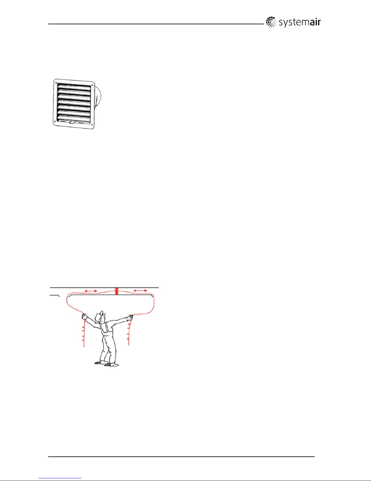
7.2Checkingtheoutdoorairintake
Leavesandpollutioncouldpluguptheairintakegrilleandreducethecapacity.Checktheairintakegrille,
andcleanasnecessary .Itisrecommendedtodothisatleasttwiceayear.
Fig.12Intakegrill
7.3Checkingtheroofcowl(iftted)
Theroofcowl(iftted)connectedtotheexhaustairductneedstobecheckedatleasttwiceayearand
cleanedifnecessary .
7.4Checkingandcleaningtheductsystem
Dustandgreasedepositsmaybuildupintheductsystem,evenifrequiredmaintenancesuchaschanging
ofltersisbeingcarriedout.Thiswillreducetheefciencyoftheinstallation.
Theductrunsshouldthereforebecleaned/changedwhennecessary .Steelductscanbecleaned
bypullingabrushsoakedinhotsoapywaterthroughtheductviadiffuser/louvreopeningsorspecial
inspectionhatchesintheductsystem(iftted).
Itisrecommendedtodothisevery5yearsandisnormallycarriedoutbyauthorizedcompanies
specializedinthisarea.
Fig.13Cleaningductsystem
8Troubleshooting
Awarningtrianglewithtextinthedisplayindicatesanalarm.Turnmenuselectortothewarningtriangle
andpressconrmtwicetoviewthealarm.
SAVEVTR150/KUserManual
207997
15
SystemairAB
Page 18

8.1Alarmlist
AlarmExplanation
Dothefollowing
FanIndicateserroroneithersupply
orextractairfan.
Thealarmisdisplayedinthe
controlpanel.
Contactyourinstallation
companyorplaceofpurchase.
EMT/Frost
Indicatestriggeredoverheat
protection(incaseofinstalled
electricre-heaterbattery)orfrost
protection(incaseofinstalled
waterheatingbattery).
Atriggeredfrostprotectionalarm
resultsinthefollowing:
•Bothfansstop.
•Outdoorandexhaustair
dampersclose.
•Watervalveopenscompletely
(10Vsignalgoesouttothe
actuator).
Theunitwillrestartoncethe
watertemperaturereaches+5C°
abovethesetfrostprotection
temperature.
Atriggeredoverheatprotection
givesanalarminthecontrol
panel.
Resetbypushingtheredbutton
onthefrontoftheheater.
Iftheproblemcontinuescontact
yourinstallationcompanyor
placeofpurchase.
Rotor
Indicatesarotormalfunction.
Thealarmisdisplayedinthe
controlpanel.
Therotatingheatexchangerhas
stopped.Checktherotorbelt.
Seechapter6.8
Iftheheatexchangerisstill
rotating,therotorsensormaybe
faulty.
Contactyourinstallation
companyorplaceofpurchase.
PbFailErrorinconnectionwithrelay
cardfortheelectricalre-heater(if
installedandactivated).
ET2maybetriggeredduetohigh
temperature.
Thealarmisdisplayedinthe
controlpanel.
Theheaterwillnotbeactivated.
FortriggeredET2,wait10–15
min.Iftheerrorremains,contact
yourinstallationcompanyor
placeofpurchase.
SAVEVTR150/KUserManual
207997
16
SystemairAB
Page 19

AlarmExplanation
Dothefollowing
Temp
Malfunctioninoneormoreofthe
temperaturesensors.
Thealarmisdisplayedinthe
controlpanel.
Contactyourinstallation
companyorplaceofpurchase.
Filter
Timeforlterchange.
Thealarmisdisplayedinthe
controlpanel.
Changelteraccordingtothe
instructionsinchapter6.4
8.2Typelabel
Beforecallingyourservicerepresentative,makeanoteofthespecicationandproductionnumberfrom
thetypelabel,whichcanbefoundonthesideoftheunits,nexttotheexternalconnections.
Fig.14T ypelabel
PositionDescription
1
Productcode(productspecication)
2Productitemnumber
3Productionordernumber
4
Serialnumber
5
Productiondate(YY .MM.DD)
SAVEVTR150/KUserManual
207997
17
SystemairAB
Page 20

lastpage
SystemairABreservestherighttomakechangesandimprovementstothecontents
ofthismanualwithoutpriornotice.
SystemairAB
Industrivägen3
SE-73930Skinnskatteberg,Sweden
Phone+4622244000
Fax+4622244099
www.systemair.com
207997
 Loading...