

Page 1
SAVE VTR 150/K
GB User Manual................................................2
SV Användarhandbok .....................................26
Document translated from English | 211568 · A003, 29
DE Bedienungsanleitung .................................50
FI Käyttöohje................................................74
Page 2

GB
User Manual
© Copyright Systemair UAB
All rights reserved
E&OE
Systemair UAB reserves the rights to alter their products without notice.
This also applies to products already ordered, as long as it does not affect the previously agreed specifications.
GB
211471 | A003, 29
Page 3

Contents
1 Disposal and recycling ...... ......... ........ ......... . .....5
2 Warnings. ......... ........ . ......... ........ . ........ ......... .5
3 Type label.. . ........ . ........ . ........ ......... ......... .......6
4 Introduction ........ ......... ......... ......... ........ ........6
5 Cooker hood .... ........ . ........ ......... ......... ......... ..6
6 Configuration ...... . ........ . ........ ......... ......... .......7
6.1 General.... . ........ ........ . ......... ........ . ........ 7
6.2 Startup wizard ....... ......... ......... ........ . .....7
6.3 Common symbols. . ........ ......... . ........ .......7
6.4 Menu overview ......... ........ . ........ ......... . .8
6.5 Home screen...... ........ . ........ ......... . ........8
6.5.1 User modes .... ......... ........ . ........ 8
6.5.2 Temperature settings .. . ........ ..... 11
6.5.3 Airflow settings . ........ . ........ . .... 12
6.5.4 Indoor Air Quality . ......... ........ . .. 12
6.5.5 Status line .... ........ . ........ . ........ 12
6.6 Description of User function icons ...... ...... 13
6.7 Week Schedule..... ........ . ........ . ........ . .. 14
6.7.1 Schedule airflow
settings......... ........ . ........ ........14
6.7.2 Edit schedule ........ . ........ . ........ 14
7 Cooker hood maintenance........ ......... ......... ..... 15
7.1 Cleaning cooker hood... . ........ ......... . ...... 15
8 Maintenance of the unit........ . ........ . ........ ........15
8.1 Warnings. ........ . ........ . ........ . ........ ........ 15
8.2 Remove/mount the outer front ...... ......... 16
8.3 Remove/mount the inner front... ......... .... 16
8.4 Changing filters.... . ........ . ........ . ........ ..... 16
8.4.1 Resetting the filter time ........ ..... 17
8.5 Checking and cleaning the heat
exchanger ........ . ........ . ........ ......... ....... 17
8.6 Cleaning the fans ........ . ........ ......... ....... 17
8.7 Replacing rotor drive belt ......... . ........ ..... 17
8.8 Overheat protection reset button . ........ . ... 19
9 Duct system maintenance .. . ........ ......... ......... .. 19
9.1 Cleaning extract louvres and supply air
diffusers........ ........ . ........ ......... ......... .. 19
9.2 Checking the outdoor air intake . ......... ..... 19
9.3 Checking the roof cowl (if fitted). ........ . .... 19
9.4 Checking and cleaning the duct
system ........ ......... ........ . ........ . ........ . .. 19
10 Troubleshooting... ......... . ........ ......... ........ . ..... 19
11 Alarms..... . ........ . ........ ......... ......... ........ . ...... 21
11.1 Alarm list...... . ........ . ........ . ........ ........ . .. 21
211471 | A003, 29
Page 4

Page 5

GB
1 Disposal and recycling
This product is compliant to the WEEE directive. When disposing the unit, follow your local rules
and regulations.
This product packing materials are recyclable and can be reused. Do not dispose in household
waste.
2 Warnings
Danger
• Make sure that the mains supply to the unit is disconnected before performing any maintenance or
electrical work!
• All electrical connections and maintenance work must be carried out by an authorized installer and in
accordance with local rules and regulations.
Warning
Disposal and recycling |
5
• This product must only be operated by a person who has suitable knowledge or training within this field
or carried out with the supervision of a suitably qualified person.
• Beware of sharp edges during mounting and maintenance. Use protective gloves.
Warning
• All though the mains supply to the unit has been disconnected there is still risk for injury due to rotating
parts that have not come to a complete standstill.
Important
• The installation of the unit and complete ventilation system must be performed by an authorized installer
and in accordance with local rules and regulations.
• The system should operate continuously, and only be stopped for maintenance/service.
• Do not connect tumble dryers to the ventilation system.
• Duct connections/duct ends must be covered during storage and installation.
• Make sure that filters are mounted before starting the unit.
211471 | A003, 29
Page 6
| Type label
6
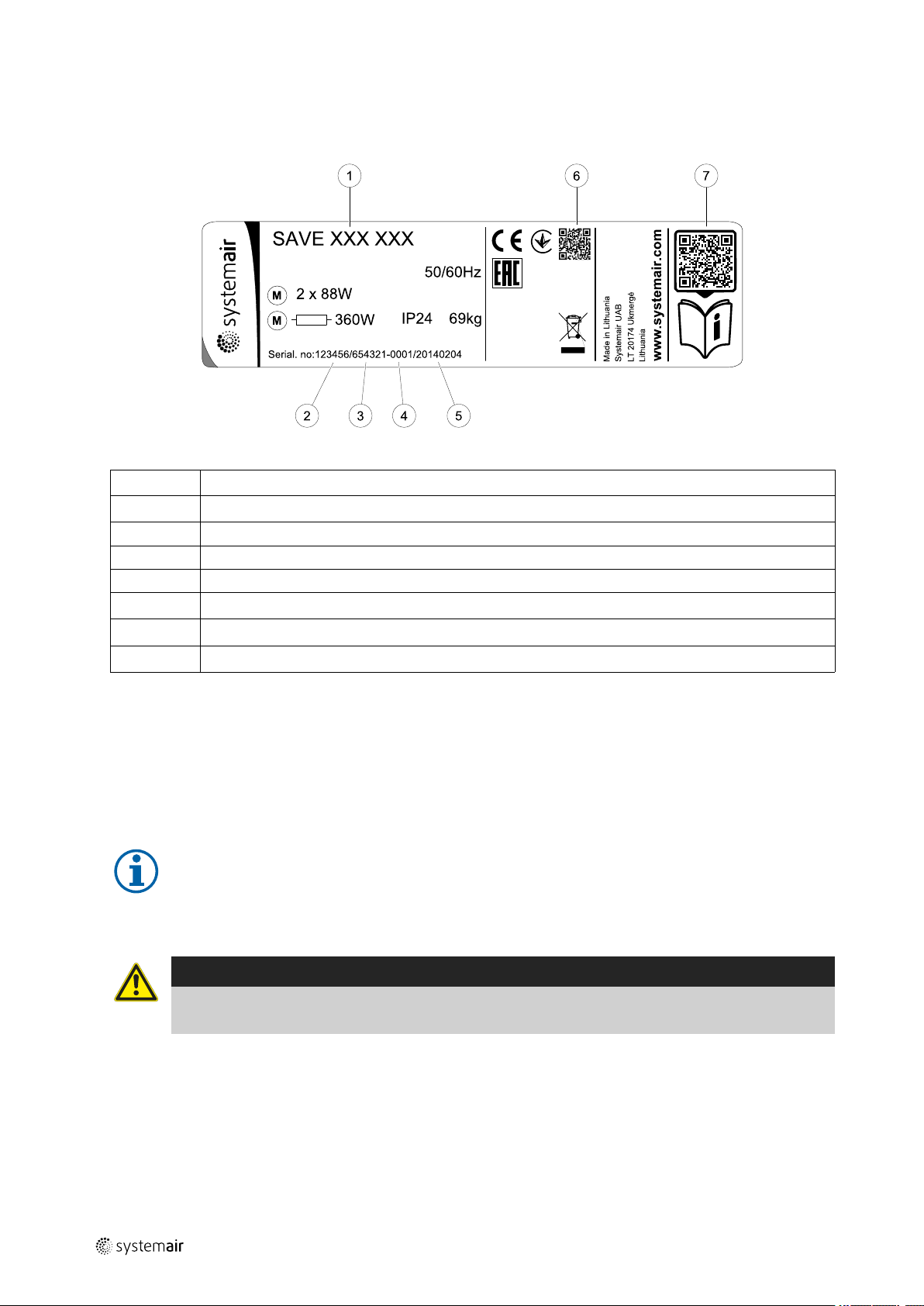
3 Type label
Before calling your service representative, make a note of the specification and production number from the type label,
which can be found on the side of the units, next to the external connections.
Fig. 1 Type label
Position Description
1
2
3
4
5
6
7
Product code (product specification)
Product item number
Production order number
Serial number
Production date (YY.MM.DD)
QR code for manufacturing order (MO) number and software version
QR code for the spare parts list and documentation
GB
4 Introduction
The SAVE VTR 150/K is a heat recovery ventilation unit with a built in rotating highly efficient heat exchanger and cooker hood. The SAVE VTR 150/K is suitable for smaller flats or houses. It supplies filtered outdoor air to residential areas
and extract air from bathroom, kitchen and wet rooms.
There are two model options, right (R) and left (L) model. Both models come with 500 W or 1000 W installed re-heater
battery. The different models are recognized by the placing of the internal components. This manual describes basic information how to operate and perform maintenance on a left (L) unit and the system it is connected to.
Note:
This document describes a left (L) model. The inside of a right (R) model is mirrored.
5 Cooker hood
Danger
• Do NOT flambé beneath the cooker hood when in use.
• Sufficient air flow must be secured to the room when the cooker hood is in use
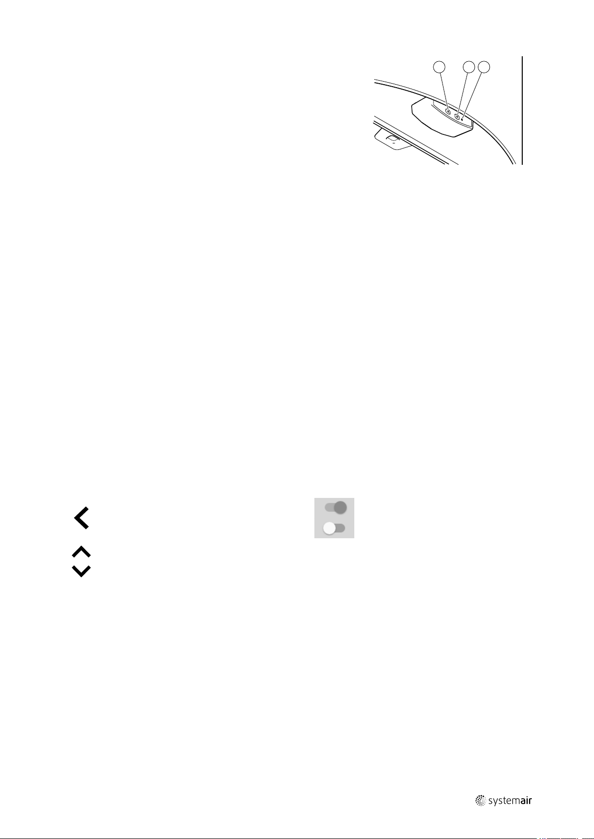
Press button A to turn on the lights.
Press button B once to open the ventilation damper when cooking. The LED indicator (C) is steadily lit.
Press button B again to force the ventilation. The LED indicator is blinking.
211471 | A003, 29
Page 7
GB
A B C
Press button B a third time to close the ventilation damper. The ventilation
fan goes back to nominal speed and the LED indicator goes off.
The damper will automatically close after 60 minutes unless it is manually
closed.
No extract air will go through the cooker hood in "off" mode. Extract air from
the kitchen needs a separate air valve.
Hint: Let the damper be open a while before and after cooking to prevent
smoke from spreading in the room.
Fig. 1 Cooker hood front panel
Configuration |
6 Configuration
6.1 General
SAVE VTR 150/K has a modern touchscreen LCD control panel, simply known as HMI — Human Machine Interface. The
touchscreen display provides information about current state of the unit and allows you to control all system functions.
Settings are done by touching the icons or options. The touch screen is sensitive and it is not necessary to press too
hard.
7
6.2 Startup wizard
During the first power up of the unit, you will be asked to set:
• menu language
• time and date
• import configuration file (if the Internet Access Module (IAM) with configuration file is available)
• airflow control type (Manual/RPM) and airflow level values
• heater type (None/Electrical/Water/Change-over)
The Startup Wizard cannot be skipped.
6.3 Common symbols
The following selection symbols are common and are present in most menu pages:
Back button to return to a previous
menu, located at the upper left corner
Up arrow to increase a value CANCEL Button to cancel changes
Down arrow to decrease a value
Some menus have more than one page. Touch page indicator in the top right corner to go to the next page. The first
number indicates current page number and the second number indicates a total number of pages available.
SET/OK
On and Off slider to activate or
deactivate a function. White bubble —
function is inactive, green bubble —
function is active.
Buttons to confirm changes
Many options show up in a form of the pop-up window. Select the option from the displayed list in the pop-up window
and press OK to confirm selection.
211471 | A003, 29
Page 8
| Configuration
8
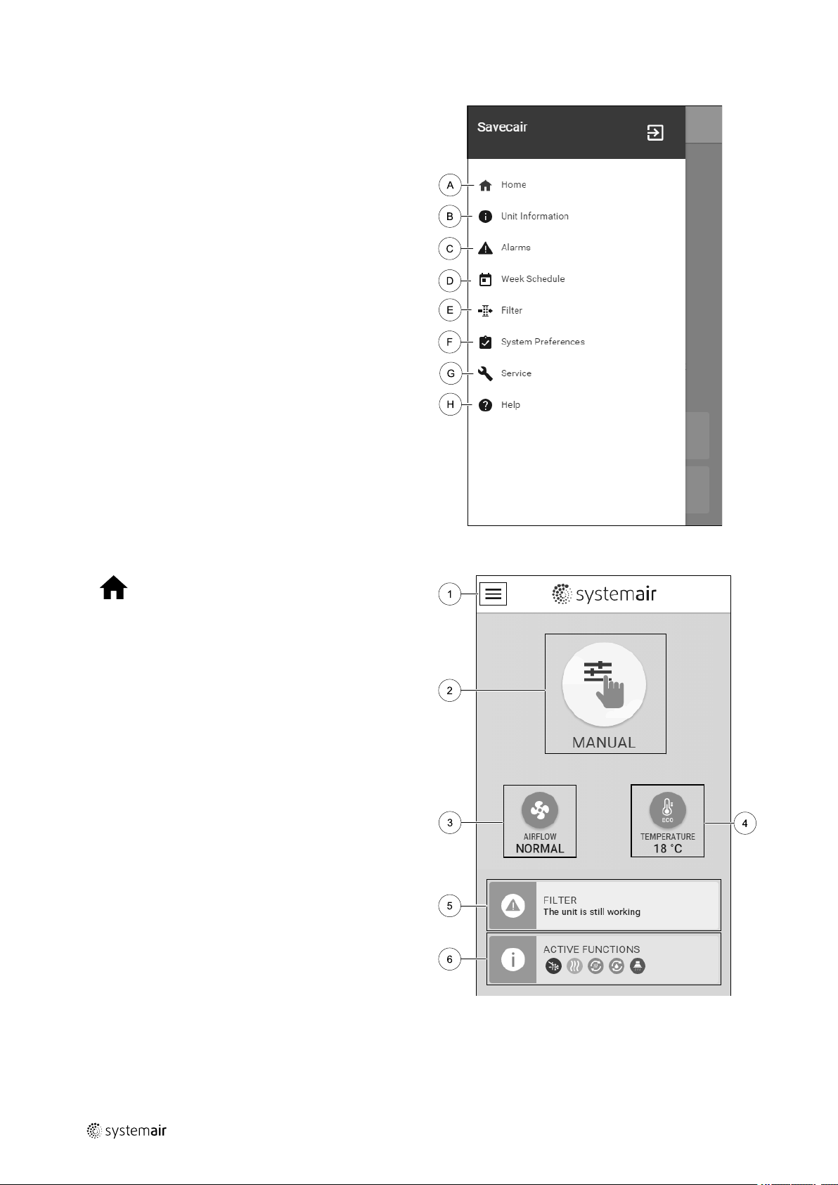
6.4 Menu overview
A.Return to home screen
B. Basic read-only information about the unit
C. Currently active alarms and alarm history
D.Configure and check week schedule
E. Check and change remaining time till filter change
F. General system preferences
G.Configuration of all system parameters
H.Help and troubleshooting menu
GB
6.5 Home screen
Touching home icon (pos. A) in drop-down menu
list (pos. 1) will always returns you to home screen after
commissioning.
1. Drop-down menu list
2. Active user mode
3. Airflow settings
4. Temperature settings
5. List of active alarms
6. Icon list of active user functions
6.5.1 User modes
The first icon at the top of home screen shows currently active user mode. To change the user mode, touch the active
user mode icon (pos. 2) and select a new user mode from the list. The unit has 2 permanent and 5 temporary user
modes available for selection. Only one mode can be active at a time.
211471 | A003, 29
Page 9

GB
Settings of all modes can be modified in Service menu.
Configuration |
6.5.1.1 Permanent modes
Permanent modes are always active unless interrupted by temporary modes, activated user functions or alarms:
9
Icon Text
AUTO
MANUAL
Automatic airflow control. AUTO mode is available for selection when Demand
Control, Week Schedule and/or external fan control functions are configured,
otherwise AUTO mode icon won’t be visible in active user modes menu. AUTO
mode activates Demand Control, Week Schedule and/or external fan control
functions. Demand is available to choose as airflow setting in Week Schedule.
Manual selection of airflow levels. The unit can be set run at one out of four
available airflow speeds: Off/Low/Normal/High.
Note:
The fan can be set to OFF by activating Manual Fan Stop function in
Service menu.
Description
6.5.1.2 Temporary modes
Temporary modes are active only for a set period of time unless interrupted by active user modes, activated user functions or alarms:
Icon Text
HOLIDAY
CROWDED
AWAY
REFRESH
FIREPLACE
Sets speed of both supply and extract air fans to Low levels when user is away
from home for a long period of time.
ECO mode is active.
Set duration in days.
Sets speed of both supply and extract air fans to maximum High levels and
temperature setpoint offset to –3 K when apartment is more crowded than usual.
Default temperature setpoint offset is –3 K.
Set duration in hours.
Sets speed of both supply and extract air fans to Low levels when user is away
from home for a short period of time.
ECO mode is active.
Set duration in hours.
Sets speed of both supply and extract air fans to maximum High levels to
replace indoor air with a fresh air in a short period of time.
Set duration in minutes.
Sets speed of supply air fan to High level and extract air fan to Low level to
increase air pressure within the apartment for better smoke extraction through
the chimney.
Set duration in minutes.
Description
Settings of all modes can be modified in Service menu.
Temporary modes and user functions are active only for a set period of time after which they are terminated and the
unit changes back to a former AUTO or MANUAL mode, depending on which one was active before temporary mode or
user function was activated.
Temporary modes can also be activated via digital input signal triggered by push button, presence detector, etc.
6.5.1.3 Digital input functions
Digital input functions always active while digital input is activated.
211471 | A003, 29
Page 10
10
| Configuration
GB
Icon Text
Central
Vacuum
Cleaner
Cooker Hood
Configurable
Digital Input
1
Configurable
Digital Input
2
Configurable
Digital Input
3
Pressure
Guard
Function sets speed of supply air fan to High level and extract air fan to Low
level to increase air pressure within the apartment for better dust collection
through central vacuum cleaner.
Function can be activated via digital input — Central Vacuum Cleaner
Function.
Sets speed of both supply and extract air fans to Maximum level to increase
airflow in the cooker hood.
Function can be activated via digital input — Cooker Hood Function.
Configurable digital input for custom user function. Airflow levels for both fans
are freely configurable.
High–priority function.
Configurable digital input for custom user function. Airflow levels for both fans
are freely configurable.
Mid–priority function.
Configurable digital input for custom user function. Airflow levels for both fans
are freely configurable.
Low–priority function.
Configurable digital input for pressure switch connection. Airflow levels for both
fans are freely configurable.
6.5.1.3.1Configurable digital inputs
Description
A custom airflow settings for supply and extract fans can be set and assigned to a digital input. Each fan can have a different airflow setting.
Configurable digital input can be activated via signal triggered by push button, presence detector or any other external
device with digital output, such as Building Management Systems (BMS)
Configurable digital inputs are grouped in levels of priority, Configurable Digital Input 1 being the highest,
meaning it can’t be overwritten by other user functions.
6.5.1.4 Digital input and Mode hierarchy
User modes and functions have a different hierarchy. User functions activated via HMI or mobile APP, such as AWAY,
CROWDED, FIREPLACE, HOLIDAY and REFRESH, are interrupted by manual selection of AUTO and MANUAL fan modes.
A FIREPLACE function has the highest priority between user functions. Other functions activated via HMI/APP can interrupt each other.
If FIREPLACE function is hard-wired on the connection board and configured as digital input (DI) then it has a higher
priority than AUTO and MANUAL mode. Digital input for a FIREPLACE function has also a higher priority than other
hard-wired digital inputs (DI) for: AWAY, CENTRAL VACUUM CLEANER, COOKER HOOD, CROWDED, HOLIDAY or REFRESH.
211471 | A003, 29
Page 11

GB
Configuration |
11
Fig. 2 Hierarchy of user modes and digital inputs
Modes are listed from the highest to lowest priority; A — user modes that can be activated from the control panel; B —
user modes and functions activated via digital input
6.5.2 Temperature settings
Temperature can be set at SET TEMPERATURE menu accessible from the home screen by touching
TEMPERATURE icon with thermometer. Default temperature value is 18°C (range 12–30°C).
Use up and down arrows or a slider to change the value.
Then touch the OK button to confirm changes.
Temperature set point is for room air temperature, supply air temperature or for extract air temperature depending on
which control mode is active. Default setting is Supply air temperature control.
Control mode of the temperature can be changed in Service menu.
6.5.2.1 ECO mode
ECO mode is a power saving function that can be activated in SET TEMPERATURE menu.
ECO mode function is available only when an internal heater is installed and configured.
While ECO mode is active, a temperature setpoint at which heater is activated is lowered to avoid activation of the heater during cold nighttime.
211471 | A003, 29
Page 12

| Configuration
12
If the temperature is very low and the heater is activated during the nighttime (even with lowered temperature setpoint), then during the upcoming daytime indoor temperature will be increased using the heat exchanger so that accumulated heat could be used during the next cold nighttime, the lowered setpoint for the heater remains.
GB
ECO mode will have impact for the following user
functions/modes if selected:
• AUTO mode
• MANUAL mode
• AWAY mode
• HOLIDAY mode
• CENTRAL VACUUM CLEANER function
• COOKER HOOD function
• FIREPLACE mode
ECO mode is always activated by the following modes:
• AWAY mode
• HOLIDAY mode
ECO mode is always deactivated by the following user
functions/modes:
• CROWDED mode
• REFRESH mode
• FREE COOLING function
6.5.3 Airflow settings
Airflow settings are available only in MANUAL mode. Click on fan icon on the main screen to enter SET
AIRFLOW menu.
Use up and down arrows or a slider to change the airflow value.
The airflow may be adjusted in these steps: Off/Low/Normal/High. These settings control output signals to the supply and extract fans.
Important
It is not recommended to set fan to Off in standard households. If manual fan stop is activated, the unit
should be provided with dampers in exhaust and fresh air ducts to avoid cold draught and risk of
condensation when the unit has been stopped.
The fan can be set to Off by activating Manual Fan Stop function in Service menu.
6.5.4 Indoor Air Quality
The unit automatically controls indoor humidity and/or CO2levels by adjusting airflow setting. Airflow is
increased if air quality is decreasing.
Demand Control function is responsible for IAQ (Indoor Air Quality) regulation. Relative humidity (RH) and/or CO
sors are responsible for IAQ monitoring.
Indoor air quality (IAQ) indicator is available if AUTO mode and Demand Control function is activated.
IAQ levels:
• ECONOMIC: Actual IAQ value is below low IAQ set point.
• GOOD: Actual IAQ value is between low and high IAQ limits.
• IMPROVING: Actual IAQ value is above high IAQ set point.
Different airflow settings can be set for IMPROVING and GOOD IAQ levels in Service menu.
2
sen-
Setpoint for relative humidity and CO
level can be set in Service menu.
2
6.5.5 Status line
Status line located at the bottom area of home screen displays information about:
211471 | A003, 29
Page 13

GB
Configuration |
13
List of active alarms. See
chapter 11.1 for more
information.
Touching any of these lines will move you to the next page with more detailed list and information about each alarm or
active user function.
List of active user functions.
See chapter 6.6 for more
information.
6.6 Description of User function icons
Icon Text
Heating
Heat recovery
Cooling
Cooling
recovery
Connected heater or pre-heater is active and air heating is in process.
Heat recovery from apartment is active.
Connected cooler is active and air cooling is in process.
Automatic cooling recovery is active when extract air temperature from
apartment is lower than outdoor air temperature and there is a cooling demand
(temperature setpoint is lower than outdoor air temperature).
No cooling recovery with heating demand. If the outdoor air temperature is
higher than then thee indoor air temperature and there is a heating demand,
function Free heating is activated instead.
Description
Free cooling
Moisture
transfer
Defrosting
Secondary air
Vacuum
cleaner
Cooker Hood
User lock
Function decreases indoor air temperature by using only cool outdoor air during
nighttime to save energy consumption.
Function controls the rotation speed of the heat exchanger to prevent moisture
transfer to supply air due to high relative humidity in the extract air.
Function is only available for units with Rotating type heat exchanger.
Function prevents formation of the ice on the heat exchanger during cold
outdoor temperatures.
Warm air from the living space is used to defrost the heat exchanger using a
damper inside the outdoor air duct. The unit switches from outdoor air to
secondary air while the extract air fan stops and warm secondary air increases
the temperature inside the heat exchanger.
Function sets speed of supply air fan to High level and extract air fan to Low
level to increase air pressure within the apartment for better dust collection
through central vacuum cleaner.
Function can be activated via digital input — Central Vacuum Cleaner
Function.
Always active while digital input is activated.
Sets speed of both supply and extract air fans to Maximum level to increase
airflow in the cooker hood.
Function can be activated via digital input — Cooker Hood Function.
Function indicates that the system is locked with a password and cannot be
edited or settings changed in any way. System must be unlocked first to make
changes.
211471 | A003, 29
Configurable
Digital Input
1
Configurable
Digital Input
2
Configurable digital input for custom user function. Airflow levels for both fans
are freely configurable.
High–priority function.
Configurable digital input for custom user function. Airflow levels for both fans
are freely configurable.
Mid–priority function.
Page 14
14
| Configuration
GB
Configurable
Digital Input
3
Pressure
Guard
Configurable digital input for custom user function. Airflow levels for both fans
are freely configurable.
Low–priority function.
Configurable digital input for pressure guard connection. Airflow levels for both
fans are freely configurable.
6.7 Week Schedule
The unit can be configured to operate at set airflow levels up to two time periods (00:00–23:59) on user
selected days.
Week Schedule is active only during AUTO mode.
6.7.1 Schedule airflow settings
Touch settings icon to go to SCHEDULE AIRFLOW SETTINGS menu. In this menu set airflow level for
scheduled and unscheduled periods. Available levels: Off, Low, Normal, High or Demand.
Set temperature setpoint offset for both periods (-10°C – 0°C).
Demand level is available only if Demand Control or External fan function is active.
6.7.2 Edit schedule
Touch icon at the bottom left corner of the screen to add a new schedule or press EDIT button to modify
already added schedule.
To configure the schedule:
1. Set the time. Touch the START TIME or END TIME values to change time. Use arrow buttons
or decrease value. Confirm with OK button.
and to increase
Note:
Scheduled time can start but never end at midnight (00:00). The latest END TIME period is 23:59.
Scheduled time cannot go to the next day.
12 or 24 hour time format can be changed in System Preferences menu.
If necessary, activate second scheduled period and set up time.
2. Once time is set, click on the day(s) when schedule should be active. It is possible to set a separate schedule for each
day.
Already scheduled days are not available for selection for new schedules.
3. Confirm schedule with OK button.
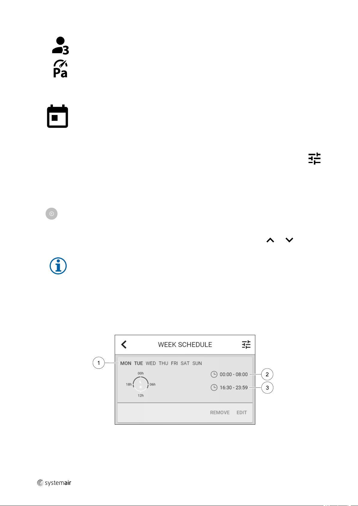
Fig. 3 Week schedule example
Scheduled days are highlighted (pos. 1). First time period (pos. 2) and the second time period (pos. 3) are shown on the
right side of each schedule.
211471 | A003, 29
Page 15

GB
7 Cooker hood maintenance
7.1 Cleaning cooker hood
Warning
There is fire hazard if the cooker hood is not cleaned within given intervals.
• The filter is to be cleaned every second month during
normal use. Clean more often during intense use.
• Clean the inside of the cooker hood at least twice a
year.
Remove the filter as shown in the image:
The metal grease filter can be cleaned in a dishwasher or
by hand using a mild detergent or liquid soap. When replacing, ensure that it is dry.
The other parts of the cooker hood are wiped with a
damp cloth and mild liquid household cleaner. Never use
abrasive cleaning materials.
Cooker hood maintenance |
Fig. 2 Remove cooker hood filter
15
8 Maintenance of the unit
Maintenance of the SAVE VTR 150/K should normally be performed 3 - 4 times a year.
8.1 Warnings
Danger
• Make sure that the mains supply to the unit is disconnected before performing any maintenance or
electrical work!
• All electrical connections and maintenance work must be carried out by an authorized installer and in
accordance with local rules and regulations.
Warning
• This product must only be operated by a person who has suitable knowledge or training within this field
or carried out with the supervision of a suitably qualified person.
• Beware of sharp edges during mounting and maintenance. Use protective gloves.
Warning
• All though the mains supply to the unit has been disconnected there is still risk for injury due to rotating
parts that have not come to a complete standstill.
Important
• The installation of the unit and complete ventilation system must be performed by an authorized installer
• The system should operate continuously, and only be stopped for maintenance/service.
• Do not connect tumble dryers to the ventilation system.
• Duct connections/duct ends must be covered during storage and installation.
• Make sure that filters are mounted before starting the unit.
211471 | A003, 29
and in accordance with local rules and regulations.
Page 16
| Maintenance of the unit
16
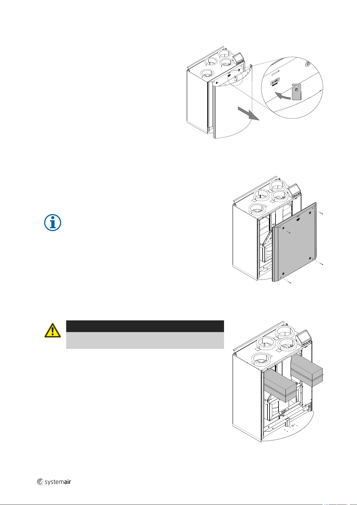
8.2 Remove/mount the outer front
The outer front is mounted with four pins and is removed
by pushing the locking hock to the left and pulling the
front towards you.
Re-mount the outer front in reverse order.
8.3 Remove/mount the inner front
The inner front is mounted with four screws. Loosen the screws and pull the
inner front towards you.
GB
Fig. 3 Remove/mount the outer front
Mount the inner front and tighten the mounting screws properly to prevent
air leakage.
Note:
When mounting the inner front, note the two guide screws at the
bottom of the inner front. These screws shall be fitted into the
two slots in the inner hatch support bracket.
8.4 Changing filters
Danger
Make sure that the Mains supply to the unit is disconnected
before performing any maintenance or electrical work!
The filters are to be changed every 3–15 months, default value is 12 months.
When the filters have been changed the filter timer will reset automatically
after alarm is acknowledged.
Fig. 4 Remove/mount the inner front
The factory installed filters are of filter quality M5/ePM10 50% for the supply
air and M5/ePM10 50% for the extract air filter. The filters need to be replaced when polluted. New sets of filters can be acquired from your installer
or wholesaler.
Filter quality M5/ePM10 50% can be installed for supply air filtering.
The filter type is labelled on the top of the filter.
Fig. 5 Heat exchanger filters
211471 | A003, 29
Page 17
GB
Maintenance of the unit |
8.4.1 Resetting the filter time
Once filter is changed, it is necessary to reset filter time. Go to Filter menu (see 6.4 Menu overview, page 8, pos. E)
or if filter alarm is present, click on alarm status line (see 6.5 Home screen, page 8, pos. 5) and select filter alarm. Select
CHANGE FILTER, in the pop up menu define a new filter period and press OK to confirm selection.
Filter time is now reset.
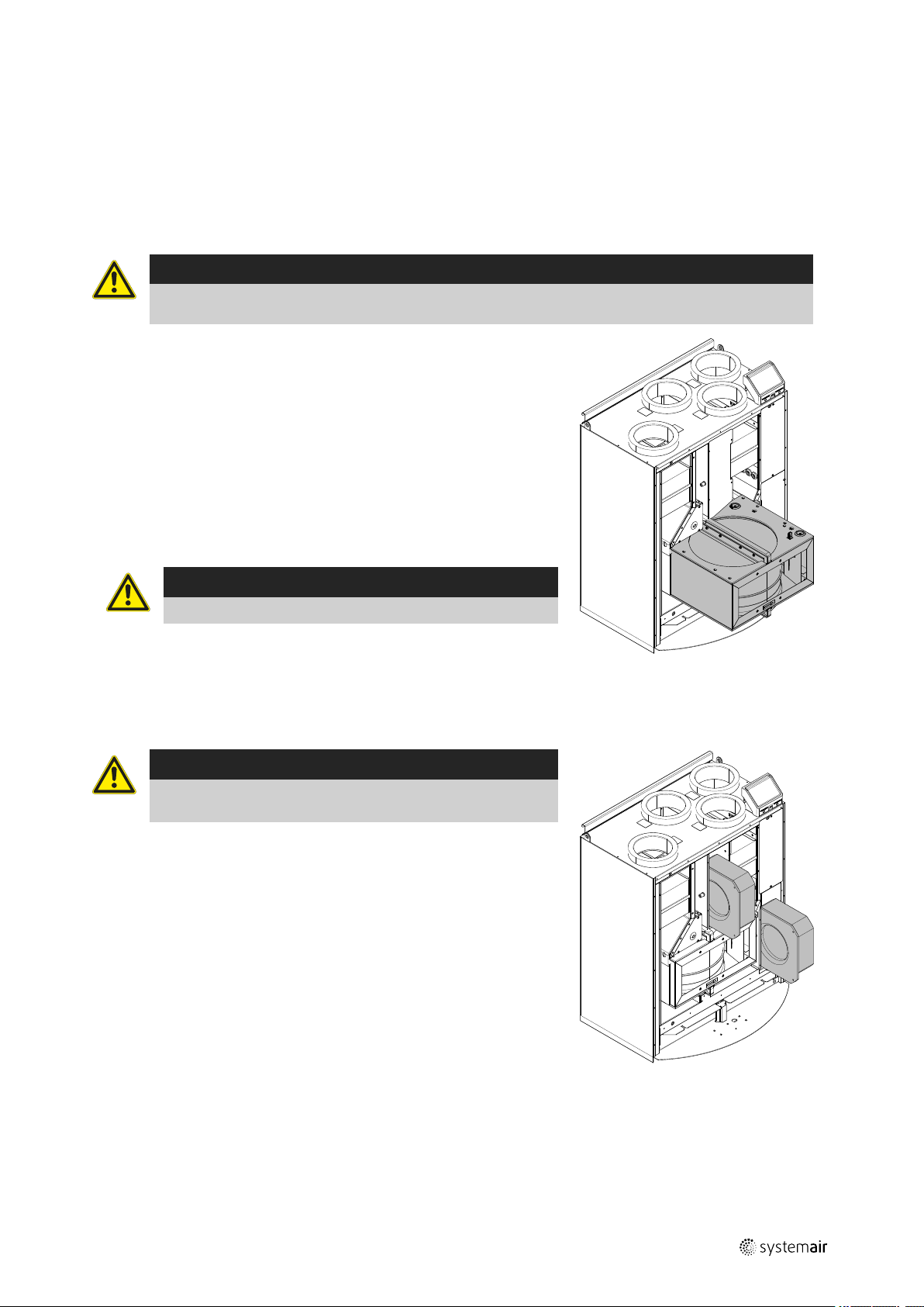
8.5 Checking and cleaning the heat exchanger
Danger
• Make sure that the Mains supply to the unit is disconnected before performing any maintenance or
electrical work!
Even if the required maintenance is carried out, dust will build up in the exchanger block. It is therefore of vital importance for the upkeep of a high efficiency that the exchanger block is removed from the unit and cleaned
periodically as illustrated below. Clean the heat exchanger at least every 3
years or when required.
1. Disconnect the rotor power supply and the rotor sensor. The cables are
found beside the rotor at the back.
2. Pull out the rotor towards you. Some force may be needed.
3. Clean the rotor.
Wash in hot soapy water. Do not use detergent containing ammonia. Rinse
using, for instance, a shower handle.
17
Warning
Ensure the rotor motor is not exposed to moisture
4. Remount the rotor. Don’t forget to reconnect the rotor power and sensor
cables.
8.6 Cleaning the fans
Danger
• Make sure that the Mains supply to the unit is disconnected
before performing any maintenance or electrical work!
The motor bearings are life time lubricated and maintenance free.
Even if the required maintenance, such as changing of filters is carried out,
dust and grease may slowly build up inside the fans. This will reduce the
efficiency.
The fans may be cleaned as illustrated in below procedure.
1. Disconnect the fan power cables. The cables are found beside the fan at
the back.
2. Pull out the fans towards you. Some force may be needed.
3. Clean the fans with a cloth or a soft brush. Do not use water. White spirit
can be used to remove obstinate deposits.
Allow the fans to dry properly before remounting.
4. Remount the fans. Don’t forget to reconnect the fan power cables.
Fig. 6 Heat exchanger
Fig. 7 Extract and supply air fans
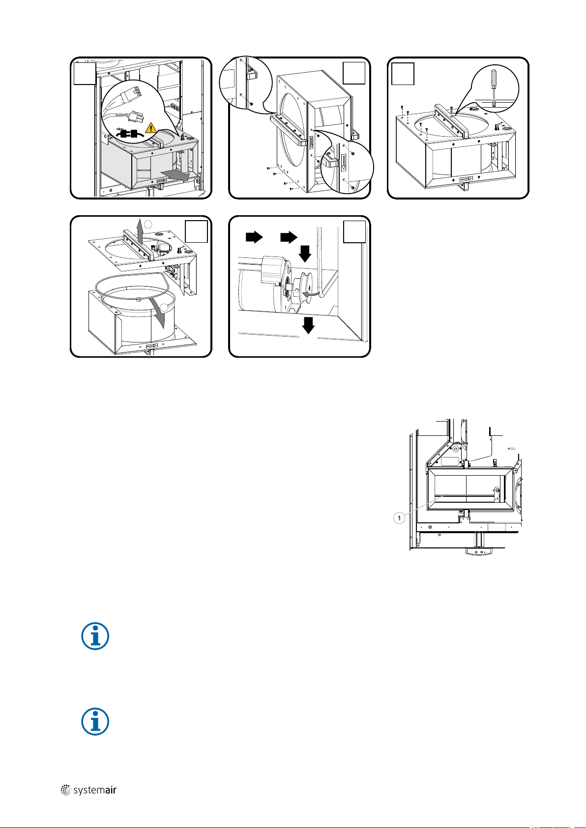
8.7 Replacing rotor drive belt
If the alarm Rotor guard is raised, see chapter 11.1, the rotor drive belt may be damaged or broken.
A spare drive belt is already placed on the heat exchanger rotor and delivered with the unit.
211471 | A003, 29
Page 18
| Maintenance of the unit
18
GB
A
11
22
11
D
22
D
C
B
B
C
E
A
In case both welded belts break it is possible to use joint nipple as a temporarily quick repair solution until the welded
belt can be replaced with a new one. Depending of how the unit is installed, it may be not necessary to remove the
heat exchanger package in order to temporary repair a broken drive belt if the belt pulley can be accessed.
Temporary belt repair solution
1. Stop the unit by disconnecting the mains.
2. Open and remove the side cover.
3. Remove the broken drive belt.
4. Use tape to attach the drive belt to the rotating heat exchanger, and rotate
the exchanger by hand to get hold of the drive belt.
5. Remove the tape and put the ”empty” end on to the nipple. Press the ends
firmly towards each other and tighten the nipple.
Fig. 8 Rotor drive belt
6. Pull the drive belt on to the belt pulley and rotate the exchanger by hand. Check that the belt pulley rotates.
Note:
If the drive belt slips, the drive belt may be too long and needs to be shortened. Cut the drive belt 5 mm
and go to step 5.
7. Replace and lock the side cover and connect the unit to mains.
8. Check that the alarm has ceased on the Control Display.
Note:
If the alarm remains, check the rotor sensor.
211471 | A003, 29
Page 19
GB Duct system maintenance
|
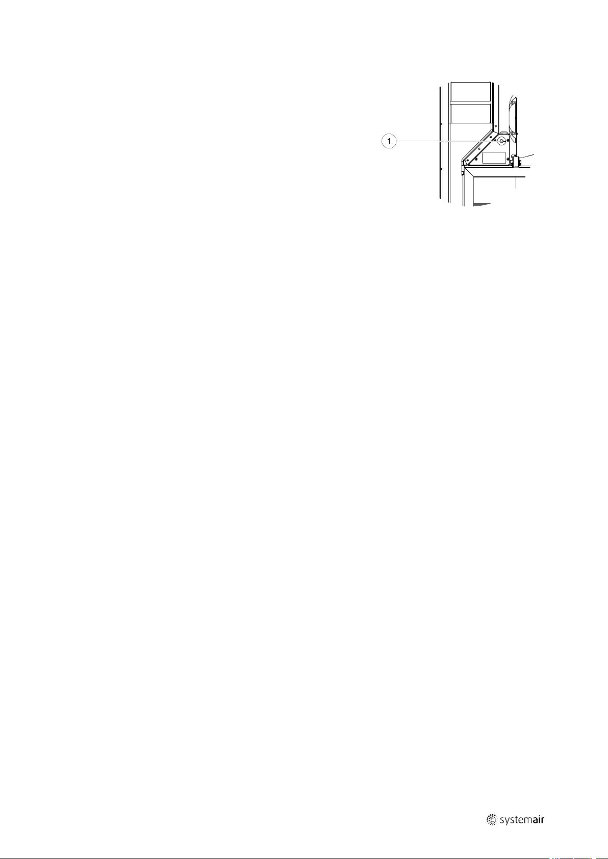
8.8 Overheat protection reset button
If the supply air temperature is low, it can indicate that the over heat protection is triggered. The overheat protection can be reset by pressing the reset
button.
9 Duct system maintenance
9.1 Cleaning extract louvres and supply air diffusers
The system supplies fresh air to your home and extracts the used indoor air via the duct system and diffusers/louvres.
Diffusers and louvres are mounted in ceilings/walls in bedrooms, living room, wet rooms, WC etc. Remove diffusers
and louvres and wash in hot soapy water as required (diffusers/louvres must not be exchanged). Cleaning of diffusers/
louvres can be done as necessary.
19
9.2 Checking the outdoor air intake
Leaves and pollution could plug up the air intake grille and reduce the capacity. Check the air intake grille, and clean as
necessary. It is recommended to do this at least twice a year.
9.3 Checking the roof cowl (if fitted)
The roof cowl (if fitted) connected to the exhaust air duct needs to be checked at least twice a year and cleaned if
necessary.
9.4 Checking and cleaning the duct system
Dust and grease deposits may build up in the duct system, even if required maintenance such as changing of filters is
being carried out. This will reduce the efficiency of the installation.
The duct runs should therefore be cleaned/changed when necessary. Steel ducts can be cleaned by pulling a brush
soaked in hot soapy water through the duct via diffuser/louvre openings or special inspection hatches in the duct system (if fitted).
It is recommended to do this every 5 years and is normally carried out by authorized companies specialized in this area.
10 Troubleshooting
If problems should occur, please check the items below before calling your service representative.
211471 | A003, 29
Page 20
| Troubleshooting
20
GB
Malfunction
Fans do not start
Reduced airflow
Action
1. Check the HMI for alarms.
2. Check that all fuses and fast couplings are connected (main power supply and fast
couplings for supply and extract air fans).
3. Check that the week schedule is ON and running in AUTO mode. The week schedule
might be in OFF mode with the air flow set to OFF (chapter 6.7).
1. Check the HMI for alarms. Some alarms can reduce the airflow to LOW if active.
2. The unit could be in defrost mode. This reduces the fan speed and in some cases shuts
down the supply air fan completely during the defrosting cycle. The fans go back to
normal after finished defrosting. There should be a defrosting function icon visible in the
APP or HMI home screen if defrosting is active.
3. If the outdoor air temperature is below 0°C (Outdoor air temperature sensor (OAT)
measures < 0°C) outdoor airflow compensation function can be active (if enabled). Fan
speed (Supply or Supply/Extract air fans) is linearly reduced for decreasing outdoor air
temperature.
4. Check if temporary user mode that reduces airflow is not activated, for example AWAY,
HOLIDAY, etc. Also check digital inputs CENTRAL VACUUM CLEANER and COOKER HOOD.
5. Check setting of airflow in the HMI.
6. Check week schedule settings (chapter 6.7).
7. Check filters. Is change of filters required?
8. Check diffusers/louvres. Is cleaning of diffusers/louvres required?
9. Check fans and heat exchange block. Is cleaning required?
10.Check if the buildings air intake and roof unit (exhaust) have been clogged.
11.Check visible duct runs for damage and/or build up of dust/pollution.
12.Check diffuser/louvre openings.
The unit cannot be
controlled (control
functions are stuck)
Low supply air
temperature
Noise/vibrations
1. Reset control functions by pulling out the plug for 10 seconds.
2. Check the modular contact connection between the HMI and the main printed circuit
board.
1. Check the display for alarms.
2. Check the active user functions in HMI screen if Defrosting function is running.
3. Check set supply air temperature in the HMI.
4. Check if ECO mode is activated in HMI (it is a power saving function and prevents the
heater from activating).
5. Check if user modes HOLIDAY, AWAY or CROWDED are activated in the HMI or via a
hardwired switch.
6. Check the analogue inputs in the service menu to verify that the temperature sensors
are functioning correctly.
7. In case of installed electrical/other re-heater battery: Check if the overheat protection
thermostat is still active. If necessary, reset by pressing the red button on the front plate
of the electrical re-heater.
8. Check if the extract filter must be changed.
9. Check if the unit has a re-heater battery connected. At very cold outdoor conditions an
electrical or water heating battery might be necessary. A re-heater battery can be
acquired as an accessory.
1. Clean fan impellers.
2. Check that the screws holding the fans are tightened.
3. Check that the anti vibration lists are fitted to the mounting bracket and to the back of
the unit.
4. Check that the rotor belt is not slipping if the unit has rotating heat exchanger.
211471 | A003, 29
Page 21
GB
Alarms |
11 Alarms
Press HELP button on the active alarm to access FAQ and troubleshooting (if available). Press ACKNOWLEDGE on the individual alarm to clear it. Depending on alarm type and the cause, it might be necessary to do a troubleshooting first to
acknowledge active alarm.
It may be not possible to clear the status of alarm if the cause of alarm is still present, as that would immediately trigger
alarm to return.
11.1 Alarm list
Alarm name Explanation Do the following
Frost protection
Frost protection temperature
sensor
Defrosting error
Supply air fan rpm
Extract air fan rpm
Supply air fan control error
Extract air fan control error
Fire alarm
Frost protection of return water in
heating coil.
• Alarm stops the unit and opens
the water valve completely.
Indicates malfunction of water
heater temperature sensor.
• Alarm stops the unit.
Indicates failure of pre-heater to
preheat the incoming outdoor air (in
case Extra controller is configured as
Preheater).
• Alarm stops the unit.
Rotation speed of the supply air fan
is lower than minimum required. Fan
malfunction.
• Alarm stops the unit.
Rotation speed of the extract air fan
is lower than minimum required. Fan
malfunction.
• Alarm stops the unit.
Flow or pressure alarm for supply air.
The pressure is bellow pressure limit.
• Alarm stops the unit.
Flow or pressure alarm for extract
air. The pressure is bellow pressure
limit.
• Alarm stops the unit.
Fire alarm is active.
• Alarm stops the unit.
The alarm will reset once the water
temperature reaches 13°C.
Check the water fluid temperature in
heating coil.
Check the circulation pump of water
heater. Contact your installation
company or place of purchase.
Check that frost protection
temperature sensor is connected
properly and cable is not damaged.
Contact your installation company or
place of purchase.
Check the pre-heater reset button.
Check the pre-heater cabling.
Contact your installation company or
place of purchase.
Defrosting error may be caused by
extremely low outdoor air
temperatures or pre-heater failure.
Check quick connectors of the fan.
Contact your installation company or
place of purchase.
Check quick connectors of the fan.
Contact your installation company or
place of purchase.
Check that air tube for pressure
sensor is connected properly and
cable is not damaged.
Contact your installation company or
place of purchase.
Check that air tube for pressure
sensor is connected properly and
cable is not damaged.
Contact your installation company or
place of purchase.
Once the external Fire alarm is
disabled – alarm has to be
acknowledged and unit restarted.
21
211471 | A003, 29
Page 22
| Alarms
22
Alarm name Explanation Do the following
Emergency thermostat
Bypass damper
Rotor guard
Secondary air damper
Outdoor air temperature
sensor
Overheat temperature sensor
Supply air temperature
sensor
Room air temperature sensor
Indicates triggered overheat
protection (in case of installed
electric re-heater battery).
Indicates malfunction in bypass
damper.
Indicates a rotor malfunction.
No rotation guard signal for 180
seconds.
Secondary air defrosting failed.
Outdoor air temperature sensor
measures < 10°C in 2 sec after
defrosting
OR
Outdoor air temperature sensor
measures < 5°C in 5 min after
defrosting
Indicates outdoor air temperature
sensor malfunction.
Indicates overheat temperature
sensor malfunction.
Indicates supply air temperature
sensor malfunction.
Indicates room air temperature
sensor malfunction.
A triggered manual or automatic
overheat protection (EMT) gives an
alarm in the control panel.
In case a manual overheat protection
is triggered, reset it by pushing the
reset button.
If the automatic overheat protection
is triggered, it will reset
automatically once the temperature
has dropped.
If the problem continues contact
your installation company or place of
purchase.
Disconnect the main power supply
for 10 seconds to reset control
function.
Power up the unit, an automatic
bypass damper test will be
performed.
If the alarm occurs again after
approximately 2 minutes – contact
your installation company or place of
purchase.
If the rotating heat exchanger has
stopped. Check the rotor belt.
If the heat exchanger is still rotating,
check that the quick connector for
the sensor is connected and that
there is an air gap of 5-10 mm
between the sensor and the magnet.
Adjust the gap if necessary.
If the alarm persists, the rotor sensor
may be faulty. Contact your
installation company or place of
purchase.
Check if secondary air damper is in
correct position.
Check that damper is connected
properly and cable is not damaged.
Contact your installation company or
place of purchase.
Check that sensor is connected
properly and cable is not damaged.
Contact your installation company or
place of purchase.
Check that sensor is connected
properly and cable is not damaged.
Contact your installation company or
place of purchase.
Check that sensor is connected
properly and cable is not damaged.
Contact your installation company or
place of purchase.
Check that sensor is connected
properly and cable is not damaged.
Contact your installation company or
place of purchase.
GB
211471 | A003, 29
Page 23
GB
Alarm name Explanation Do the following
Extract air temperature
sensor
Extra controller temperature
sensor
Efficiency temperature
sensor
PDM RH
PDM RH Extract air
temperature
Filter warning
Filter
Extra controller alarm
External stop
Manual fan stop active
Overheat temperature
Low supply air temperature
Indicates extract air temperature
sensor malfunction.
Indicates extra controller
temperature sensor malfunction.
Indicates efficiency temperature
sensor malfunction.
Indicates internal relative humidity
sensor malfunction.
Active: measured humidity = 0%
Returned: measured humidity > 5%
Indicates internal extract air
temperature sensor malfunction.
Active: measured temperature = 0°C
Returned: measured temperature >
5°C
Notification about filter change. Filter have to be replaced in one
Time for filter change. Change the filter.
Error from external device. Check if external device is connected
Unit is stopped by external signal. Operation is stopped by digital signal
Operation stopped, fans are in
manual mode and selected as OFF.
Temperature after reheater is too
high.
Active: (Overheat temperature
sensor measures > 55°C)
Returned: (Overheat temperature
sensor measures < 50°C)
Supply air temperature is too low.
Active: (Outdoor air temperature
sensor measures < 0°C) AND (Supply
air temperature sensor measures <
5°C)
Returned: (Supply air temperature
sensor measures > 10°C)
Check that sensor is connected
properly and cable is not damaged.
Contact your installation company or
place of purchase.
Check that sensor is connected
properly and cable is not damaged.
Contact your installation company or
place of purchase.
Check that sensor is connected
properly and cable is not damaged.
Contact your installation company or
place of purchase.
Check that sensor is connected
properly and cable is not damaged.
Contact your installation company or
place of purchase.
Check that sensor is connected
properly and cable is not damaged.
Contact your installation company or
place of purchase.
month time. Please acquire new
filters.
Change filter according to the
instructions in the User Manual.
Details about filter retailers can be
found in Help menu.
properly and cable is not damaged.
Reset overheat protection on
electrical pre-heater. Contact your
installation company or place of
purchase.
from external remote device or
signal from building management
system.
Select another speed of fans (LOW /
NORMAL / HIGH) or AUTO mode in
HMI home screen.
Alarm is possible if supply airflow is
too low when the reheater is
switched on.
Check the supply airflow.
Check that intake grille is not
blocked.
Check that shut off damper for
outdoor air is open in operation.
Contact your installation company or
place of purchase.
Check the heat exchanger and reheater or refer to Point 2 in
“Troubleshooting” menu.
Alarms |
23
211471 | A003, 29
Page 24
| Alarms
24
Alarm name Explanation Do the following
CO₂
External CO
sensor malfunction. Check that sensor is connected
2
properly and cable is not damaged.
In case sensor wireless – check
RS485 gateway status and sensor
status in HMI.
Contact your installation company or
place of purchase.
RH
External relative humidity sensor
malfunction.
Check that sensor is connected
properly and cable is not damaged.
In case sensor wireless – check
RS485 gateway status and sensor
status in HMI.
Contact your installation company or
place of purchase.
Output in manual mode
One or more of analogue outputs are
in manual mode.
Check Service menu for Output
settings, and check all configured
outputs to be in Auto mode. If any
outputs in Manual - change back to
Auto mode.
Alarm Fire Alarm can be only activated with a digital signal from a smoke/fire detection system or similar. Digital input has to be configured as Fire Alarm for this alarm to work.
GB
Digital output configured as Sum Alarm sends a generic signal every time the alarm is triggered, except for alarms Ex-
ternal stop, Output in manual mode and Manual Fan Stop. This signal does not specify the alarm type.
211471 | A003, 29
Page 25

2114711 | A003, 29
Page 26

SV
Användarhandbok
© Upphovsrätt Systemair AB
Alla rättigheter förbehållna
Med förbehåll för eventuella fel och förbiseenden
Systemair AB förbehåller sig rätten för ändringar av produkterna utan föregående meddelande.
Detta gäller även redan beställda produkter, så länge det inte påverkar tidigare överenskomna specifikationer.
SE
2114711 | A003, 29
Page 27

Innehåll
1 Avfallshantering och återvinning .... ........ . ........ . 29
2 Varning........ ........ . ........ . ........ . ........ ........ . ... 29
3 Märkskylt ...... ........ ......... . ........ ......... ........ . .. 30
4 Inledning . ......... . ........ ......... ........ . ........ . .......30
5 Köksfläkt . ......... ........ . ........ ......... . ........ ........ 30
6 Konfiguration ..... . ........ ......... . ........ ........ . ...... 31
6.1 Allmänt...... ........ . ........ ......... . ........ ..... 31
6.2 Startguide..... ......... ......... ......... ........ . .. 31
6.3 Vanliga symboler .... ........ . ........ ......... ... 31
6.4 Menyöversikt ........ ......... ......... ........ . ... 32
6.5 Hemskärmen... . ......... ........ . ........ ......... 32
6.5.1 Användarlägen ... ......... ........ . ... 32
6.5.2 Inställning av
temperatur ....... ......... ......... .... 35
6.5.3 Luftflödesinställningar ........ . ...... 36
6.5.4 Inomhusluftens kvalitet ..... . .......36
6.5.5 Statusraden...... ......... ........ ...... 36
6.6 Beskrivning av användarfunktionernas
ikoner... ......... . ........ ......... ........ . ........ . 37
6.7 Veckoschema ....... . ........ . ........ . ........ .. 38
6.7.1 Schema för
luftflödesinställningar.. . ........ . .... 38
6.7.2 Redigera schema . ......... ........ . .. 38
7 Köksfläktsunderhåll ....... ......... ......... ........ ...... 39
7.1 Rengöring av köksfläkt ..... . ........ ........ . ... 39
8 Underhåll av aggregatet . ........ . ........ ......... ...... 39
8.1 Varning....... . ........ . ........ . ........ ........ . ... 39
8.2 Demontering/montering av utvändig
front....... ........ . ......... ........ . ........ ........40
8.3 Demontering/montering av invändig
front....... ........ . ......... ........ . ........ ........40
8.4 Filterbyte..... . ........ ......... ........ . ........ . ... 40
8.4.1 Återställning av
filtertiden . ......... ........ . ........ . ... 41
8.5 Kontroll och rengöring av
värmeväxlaren . ........ . ........ . ........ ......... 41
8.6 Rengöring av fläktar .... ......... ......... .......41
8.7 Byte av rotordrivrem........ . ........ . ........ . .. 41
8.8 Återställningsknapp för
överhettningsskydd....... . ........ . ........ ..... 43
9 Underhåll av kanalsystemet.. . ........ . ........ ......... 43
9.1 Rengöring av frånluftsgaller och
tilluftsdiffusorer ....... . ........ ......... ......... . 43
9.2 Kontroll av uteluftsintag.. ......... ......... ..... 43
9.3 Kontroll av takhuv (om sådan
finns)...... ........ . ........ . ........ . ........ ........43
9.4 Kontroll och rengöring av
kanalsystemet.... ......... ........ ......... . ...... 43
10 Felsökning .. . ........ ........ . ........ . ........ . ........ ..... 43
11 Larm ...... . ........ ......... ......... ........ . ........ . .......45
11.1 Larmlista ..... ........ . ........ . ........ . ........ .... 45
2114711 | A003, 29
Page 28

Page 29
SV
1 Avfallshantering och återvinning
Denna produkt är i överensstämmelse med direktivet om elektriskt och elektroniskt avfall. Vid
kassering av aggregatet ska lokala regler och föreskrifter följas.
Produktens förpackningsmaterial är återvinningsbart och kan återanvändas. Släng inte med
hushållsavfall.
2 Varning
Fara
• Säkerställ att spänningsmatningen är bruten före underhållsarbete och elarbete.
• Arbete med elektriska anslutningar och underhåll får endast utföras av behörig personal och i enlighet
med gällande krav och föreskrifter.
Varning
Avfallshantering och återvinning |
29
• Denna produkt får endast användas av en person som har lämplig kunskap eller utbildning inom detta
område eller står under överinseende av en person med lämpliga kvalifikationer.
• Se upp för vassa kanter vid installation och underhåll. Använd skyddshandskar.
Varning
• Det dröjer något innan alla rörliga delar stannat helt efter att aggregatet kopplats bort från elnätet – risk
för personskada.
Viktigt
• Aggregatet och hela ventilationssystemet ska installeras av behörig personal och i enlighet med gällande
krav och föreskrifter.
• Systemet bör ständigt vara i gång och får bara stoppas vid underhåll/service.
• Anslut inte torktumlare till ventilationssystemet.
• Kanalanslutningar/kanaländar ska vara täckta vid förvaring och installation.
• Kontrollera att alla filter är monterade innan du startar aggregatet.
2114711 | A003, 29
Page 30

| Märkskylt
30
3 Märkskylt
Ha aggregatets huvuddata och tillverkningsnummer till hands när du kontaktar servicetekniker. Uppgifterna finns på
märkskylten på aggregatets sida, nära de externa anslutningarna.
Fig. 1 Märkskylt
SV
Position
1
2
3
4 Serienummer
5
6
7
Beskrivning
Produktkod (produktspecifikation)
Artikelnummer för produkten
Produktionsordernummer
Tillverkningsdatum (ÅÅ.MM.DD)
QR kod för tillverkningsorder (MO) nummer och version av programvara
QR kod för reservdelslista och dokumentation
4 Inledning
SAVE VTR 150/K är ett ventilationsaggregat med värmeåtervinningsfunktion med högeffektiv inbyggd roterande värmeväxlare och köksfläkt. SAVE VTR 150/K är lämplig för mindre lägenheter och småhus. Aggregatet förser bostadsutrymmen med filtrerad uteluft och evakuerar frånluft från kök och från badrum och andra våtrum.
Aggregatet finns i vänsterutförande (L) och högerutförande (R). Båda utförandena finns med monterat eftervärmningsbatteri på 500 W eller 1000 W . De olika modellerna känns igen på placeringen av de interna komponenterna. Den här
instruktionsboken innehåller grundläggande information om användning och underhåll av ett aggregat i vänsterutförande (L) och det system det är anslutet till.
Obs!
I handboken beskrivs vänsterutförandet (L). Högerutförandet (R) är invändigt en spegelvändning av
vänsterutförandet.
5 Köksfläkt
Fara
• Flambera INTE under köksfläkten när den används.
• Tillräckligt luftflöde måste säkerställas till rummet medan köksfläkten används.
Tryck på knapp A för att tända lamporna.
Tryck på knapp B en gång för att öppna ventilationsspjället under matlagning. Indikatorn (C) lyser med fast sken.
Tryck på knapp B igen för att forcera ventilationen. Indikatorn blinkar.
2114711 | A003, 29
Page 31

SV
A B C
Tryck på knapp B en tredje gång för att stänga ventilationsspjället. Ventilationsfläkten återgår till nominell hastighet och indikatorn slocknar.
Om spjället inte har stängts manuellt stängs det automatiskt efter 60
minuter.
Ingen frånluft strömmar genom köksfläkten när den är avstängd. Frånluft från
köket kräver en separat luftventil.
Tips! Låt spjället vara öppet en stund före och efter matlagning för att hindra
os från att sprida sig i rummet.
Fig. 9 Köksfläktens frontplåt
Konfiguration |
6 Konfiguration
6.1 Allmänt
SAVE VTR 150/K har en modern LCD-pekskärmsmanöverpanel, vanligtvis benämnd HMI - (Human Machine Interface).
Displayen ger information om aggregatets aktuella status och gör att du kan styra alla systemfunktioner.
Inställningar görs genom att röra vid ikonerna eller alternativen. Pekskärmen är känslig och det är inte nödvändigt att
trycka för hårt.
31
6.2 Startguide
Under den första påslagningen av aggregatet blir du ombedd att ange:
• Menyspråk
• Tid och datum
• importera konfigurationsfil (om internetåtkomstmodulen (IAM) och konfigurationsfil finns tillgängliga)
• Luftflödesregleringstyp (manuell/Varvtal) och luftflödesnivåvärdena.
• Typ av värmare (Ingen//ElektriskVattenKombi-batteri)
Det går inte att hoppa över startguiden (”Startup Wizard”).
6.3 Vanliga symboler
Följande symboler är vanliga och förekommer i de flesta menysidor:
Knappen tillbaka för att gå tillbaka till
en föregående meny, finns i det övre
vänstra hörnet
Uppåtpilen för att öka ett värde AVBRYT Knapp för att avbryta ändringar
Nedåtpilen för att minska ett värde
Vissa meny har flera än en sida. Tryck på sidans indikator i det övre högre hörnet för att gå till nästa sida. Ex (1/2) Den
första siffran anger det aktuella sidonumret och den andra siffran anger den totala summan av alla sidor.
STÄLL
IN/OK
På- och avreglaget finns för att
aktivera eller avaktivera en funktion.
Vit bubbla - funktion är inaktiv, gröna
bubbla - funktion är aktiv.
Knappar för att bekräfta ändringar
Många alternativ visas upp i en form av popup-fönster. Välj bland alternativen som visas i listan i popup-fönstret och
tryck på OK för att bekräfta valet.
2114711 | A003, 29
Page 32

| Konfiguration
32
6.4 Menyöversikt
A.Gå tillbaka till hemskärmen
B. Grundläggande skrivskyddad information om
aggregatet
C. Aktiva larm och larmhistorik
D.Konfigurera och kontrollera veckoschema
E. Kontrollera och ändra återstående tid till filterbyte
F. Allmänna systeminställningar
G.Konfiguration av alla systemparametrar
H.Hjälp- och felsökningsmeny
SV
6.5 Hemskärmen
Tryck på hemknappen (position A) i rullgardinsmenylista (position 1) tar dig alltid tillbaka till hemskärmen
efter driftsättning.
1. Rullgardinsmenylista
2. Aktivt användarläge
3. Luftflödesinställningar
4. Inställning av temperatur
5. Lista över aktiva larm
6. Ikonlista över aktiva användares funktioner
6.5.1 Användarlägen
Den första ikonen längst upp på hemskärmen visar för närvarande aktiva användarlägen. För att ändra användarläge
tryck på det aktiva användarlägets ikon (position 2) och välj ett nytt användarläge från listan. Aggregatet har 2 fasta
och 5 tillfälliga användarlägen som kan väljas. Bara ett läge åt gången kan vara aktivt.
2114711 | A003, 29
Page 33

SV
Inställningar i alla lägen kan ändras i Service- menyn.
Konfiguration |
6.5.1.1 Permanenta lägen
Permanenta lägen är alltid aktiva om de inte avbryts av tillfälliga lägen, aktiverade användarfunktioner eller larm:
33
Ikon
Text
AUTO
MANUELL
Beskrivning
Automatisk luftflödesreglering. AUTO -läge kan väljas när Behovsstyrning,
Veckoschema och/eller externa fläktstyrningsfunktioner är konfigurerade,
annars kommer AUTO symbolen inte synas i aktiva användarlägens meny. AUTO
-läget aktiverar Behovsstyrning, Veckoschema och/eller externa
fläktstyrningsfunktioner. Behov finns att välja som luftflöde i
veckoprogrammet.
Manuellt val av luftflödesnivåer. Aggregatet kan ställas in till en av fyra
tillgängliga luftflödeshastigheter: Av/Låg/Normal/Hög.
Obs!
Fläkten kan ställas in till AV genom att aktivera Manuellt Fläktstopp
funktionen i servicemenyn .
6.5.1.2 Tillfälliga lägen
Tillfälliga lägen är endast aktiva under en bestämd tidsperiod om de inte avbryts av aktiva användarlägen, aktiverade
funktioner eller larm:
Ikon
Text
SEMESTER
Beskrivning
Ställer in hastigheten för både till- och frånluftsfläktar till Låg nivå när
användaren är bortrest under en längre period.
ECO-läget är aktivt.
Inställ tid i dagar.
Ställer in hastigheten för både till- och frånluftsfläktar till maximalt höga nivåer
och temperaturvärdesförskjutning till -3 K när lägenhet är mer välbesökt än
PARTY
BORTA
VÄDRING
ELDSTAD
Inställningar i alla lägen kan ändras i Service- menyn.
Tillfälliga lägen och funktioner är endast aktiva under en bestämd tidsperiod efter vilken de avslutas och aggregatet
återgår till ett tidigare AUTOMATISKT eller MANUELLT läge beroende på vilket som var aktiverat före tillfälligt läge eller
användarfunktion var aktiverad.
Temporära lägen kan även aktiveras via digital ingångssignal som aktiveras av t.ex. en tryckknapp eller närvarogivare.
vanligt.
Standard temperaturbörvärdesförskjutning är -3 K.
Inställning av tid i timmar.
Ställer in hastigheten för både till- och frånluftsfläktar till Låg när användaren är
bortrest under en kort tid.
ECO-läget är aktivt.
Inställning av tid i timmar.
Ställer in hastigheten för både till- och frånluftsfläktar till maximala hög nivå för
att ersätta inomhusluft med frisk luft på kort tid.
Inställning av tid i minuter.
Ställer in hastigheten av tilluftsfläkt till hög nivå och frånluftsfläkten till låg nivå
för att öka lufttrycket i lägenheten för bättre rökevakuering genom skorstenen.
Inställning av tid i minuter.
6.5.1.3 Digital ingångsfunktioner
Digitala ingångsfunktionerna är alltid aktiva medan den digitala ingången är aktiverad.
2114711 | A003, 29
Page 34

34
| Konfiguration
SV
Ikon
Text
Centraldamm-
sugare
Spiskåpa
Konfigurerbar
digital
ingång 1
Konfigurerbar
digital
ingång 2
Konfigurerbar
digital
ingång 3
Tryckvakt
Funktionen ställer in hastigheten av tilluftsfläkt på hög nivå och frånluftsfläkten
till låg nivå för att öka lufttrycket inom lägenheten för bättre uppsamling av
damm genom den centrala dammsugare.
Funktionen kan aktiveras via en digital ingång Centraldammsugarfunktionen.
Ställer in hastigheten för både till- och frånluftsfläktar till Maximum nivå för att
öka luftflödet i spiskåpan.
Funktionen kan aktiveras via digital ingång – Spiskåpsfunktion.
Konfigurerbar digital ingång för egeninställd funktionalitet. Luftflödesnivåerna för
båda fläktarna kan konfigureras fritt.
Högt prioriterad funktion.
Konfigurerbar digital ingång för egeninställd funktionalitet. Luftflödesnivåerna för
båda fläktarna kan konfigureras fritt.
Normalt prioriterad funktion.
Konfigurerbar digital ingång för egeninställd funktionalitet. Luftflödesnivåerna för
båda fläktarna kan konfigureras fritt.
Lågt prioriterad funktion.
Konfigurerbar digital ingång för tryckgivaranslutning. Luftflödesnivåerna för båda
fläktarna kan konfigureras fritt.
6.5.1.3.1Konfigurerbara digitala ingångar
Beskrivning
En egeninställd luftflödesinställning för tillufts- och frånluftsfläktar kan ställas in och tilldelas en digital ingång. Varje
fläkt kan ha olika luftflödesinställningar.
Konfigurerbara digitala ingångar kan aktiveras via signal som aktiveras av en tryckknapp, närvarogivare eller någon annan extern enhet med digital utgång, så som ett BMS-system.
Konfigurerbara digitala ingångar grupperas efter prioritetsnivå, där Konfigurerbar digital ingång 1 är den högsta, vilket innebär att den inte kan skrivas över av andra användarfunktioner.
6.5.1.4 Digital ingång och hierarkiläge
Användarlägen och funktioner har en annan hierarki. Användarnas funktioner som aktiveras via HMI eller mobilapp är
sådana som BORTA, PARTY, ELDSTAD, SEMESTER och VÄDRA avbryts av manuellt val av AUTOMATISKA och MANUEL-
LA fläktlägen.
EnELDSTADSFUNKTION har högsta prioritet mellan användarfunktioner. Andra funktioner aktiveras via HMI/APP kan
störa varandra.
Om eldstadsfunktionen är fastkopplad på anslutningskortet och konfigureras som digital ingång (DI) har det därefter högre prioritet än AUTOMATISKT och manuellt läge. Den digitala ingången för en Eldstadsfunktion har också en högre prioritet än andra hårt dragna digitala ingångar (DI) för: BORTA, CENTRALDAMMSUGARE, SPISKÅPA,
PARTY, SEMESTER eller VÄDRA.
2114711 | A003, 29
Page 35

SV
Konfiguration |
35
Fig. 2 Hierarki för användarlägen och digitala ingångar
Lägen listas från högsta till lägsta prioritet; A – användarlägen som kan aktiveras från manöverpanelen; B – användarlägen och funktioner aktiverade via digital ingång
6.5.2 Inställning av temperatur
Temperaturen kan ställas in på VÄLJ TEMPERATUR-meny tillgänglig från hemskärmen genom att trycka
Temperatursymbolen med en termometer. Standard temperaturvärde är 18°C (12- 30°C).
Använd upp- och nedpilarna eller ett skjutreglage för att ändra värdet.
Tryck sedan på OK för att bekräfta ändringarna.
Temperaturbörvärdet är för rumsluftstemperatur, tilluftstemperatur eller för frånluftstemperatur beroende på vilket
kontrolläge som är aktivt. Standardinställning är tilluftstemperatur.
Kontrolläge av temperaturen kan ändras i Servicemenyn.
6.5.2.1 ECO-läge
ECOLÄGE är en energisparfunktion som kan aktiveras i VÄLJ TEMPERATUR-menyn.
ECO-läge funktion är möjlig bara när en intern värmare är installerad och konfigurerad.
Medan ECO-läget är aktivt, sänks ett temperaturbörvärde vid vilket värmaren är aktiverad för att undvika aktivering
av värmaren under den kalla natten.
2114711 | A003, 29
Page 36

| Konfiguration
36
Om temperaturen är mycket låg och värmaren aktiveras under natten (även med sänkt temperaturbörvärde), kommer
inomhustemperaturen sedan att ökas under kommande dagtid med värmeväxlaren så att lagrad värme kan användas
under nästa kalla natt, där det sänkta börvärdet för värmaren kvarstår.
SV
ECO- läget kommer att påverka de följande
funktionerna/lägena om valda:
• AUTOLÄGE
• MANUELLT LÄGE
• BORTALÄGE
• SEMESTERLÄGE
• CENTRALDAMMSUGARE
• SPISKÅPA
• ELDSTADSLÄGE
ECO-LÄGET är alltid aktiverad av följande lägen:
• BORTALÄGE
• SEMESTERLÄGE
ECO-läge avaktiveras alltid med följande funktioner/
lägen:
• PARTYLÄGE
• VÄDRINGSLÄGE
• FRIKYLNINGSFUNKTIONEN
6.5.3 Luftflödesinställningar
Luftflödesinställningarna är endast tillgängliga i manuellt läge. Klicka på fläktikonen på huvudskärmen för
att gå in på meny för att Välja LUFTFLÖDE.
Använd upp- och nedpilarna eller ett skjutreglage för att ändra luftflödets värde.
Luftflödet kan ställas in i följande steg: Av/Låg/Normal/Hög. Inställningen styr utsignalerna till tillufts- och
frånluftsfläktarna.
Viktigt
Vi rekommenderar inte att ställa in fläkten på AV i vanliga bostäder. Om manuellt fläktstopp aktiveras bör
aggregatet förses med spjäll i avlufts- och uteluftskanalerna för att undvika kallras och risk för kondens när
aggregatet har stoppats.
Fläkten kan sättas till Från genom att aktiveraManuell Fläktstoppfunktion i servicemenyn .
6.5.4 Inomhusluftens kvalitet
Enheten styr automatiskt luftfuktigheten inomhus och/eller CO2nivåerna genom att justera luftflödet.
Luftflöde ökar om luftkvalitet minskar.
Behovsstyrningsfunktionen ansvarar för IAQ (Inomhusluftens kvalitet) reglering. Relativ fuktighet (RH) och/eller
CO
-sensorerna är ansvariga för IAQ-övervakning.
2
Luftkvalitetens (IAQ) inomhusindikator finns om AUTOLÄGE och behovsstyrning är aktiverat.
IAQ-nivåer:
• EKONOMI: Faktiska IAQ-värdet är lägre än låg IAQ-börvärdet.
• BRA: Faktiska IAQ-värdet ligger mellan de låga och höga IAQ-gränserna.
• FÖRBÄTTRAS: Faktiska IAQ-värdet är högre än ett högt IAQ-börvärde.
Olika Luftflödesinställningar kan ställas in för att FÖRBÄTTRAS och BRA IAQ-nivåer i servicemenyn.
Börvärde för relativ luftfuktighet och CO
Nivån kan ställas in i servicemenyn .
2
6.5.5 Statusraden.
Statusraden i området längst ned på hemskärmen visar information om:
2114711 | A003, 29
Page 37

SV
Konfiguration |
37
Lista över aktiva larm. Se
kapitel 11.1för mer
information
Rör vid någon av dessa linjer för att gå till nästa sida med en mer detaljerad lista och information om varje larm och aktiv användarfunktion.
Lista över aktiva funktioner.
Se kapitel 6.6 för mer
information.
6.6 Beskrivning av användarfunktionernas ikoner
Ikon
Text
Värme Ansluten värmare eller förvärmare är aktiv och luftuppvärmning pågår.
Värmeåtervin-
ning
Kylning
Kylåtervin-
ning
Värmeåtervinning från lägenhet är aktiv.
Ansluten kylare är aktiv och luftkylning pågår.
Automatisk kylåtervinning är aktiv när frånluftstemperaturen från lägenhet är
lägre än uteluftstemperaturen och det finns ett kylbehov (temp. börvärde är
lägre än uteluftstemperaturen).
Ingen kylåtervinning vid uppvärmningsbehov. Om utomhustemperaturen är
högre än inomhusluftens temperatur och det finns ett uppvärmningsbehov,
aktiveras funktionen Fri uppvärmning i stället.
Beskrivning
Frikyla
Fuktöverför-
ing
Avfrostning
Sekundär luft
Dammsugare
Spiskåpa
Användarlås
Konfigurerbar
digital
ingång 1
Konfigurerbar
digital
ingång 2
Funktionen minskar inomhusluftens temperatur genom att endast använda sval
uteluft på natten för att spara energi.
Funktionen styr rotationshastigheten hos värmeväxlaren för att förhindra
fuktöverföring till tilluften på grund av för hög relativ fuktighet i frånluften.
Funktionen är endast tillgänglig för enheter med roterande värmeväxlare.
Funktionen förhindrar bildande av is på värmeväxlaren vid låga utetemperaturer.
Varm luft från vardagsrum används för att avfrosta värmeväxlaren med ett spjäll
inuti uteluftskanalen. Enheten växlar från uteluft till sekundärluft medan
frånluftsfläkten stannar och varm sekundärluft höjer temperaturen inuti
värmeväxlaren.
Funktionen ställer in hastigheten av tilluftsfläkt på hög nivå och frånluftsfläkten
till låg nivå för att öka lufttrycket inom lägenheten för bättre uppsamling av
damm genom centraldammsugare.
Funktionen kan aktiveras via en digital ingång Centraldammsugarfunktionen.
Alltid aktiv medan digital ingång är aktiverad.
Ställer in hastigheten för både till- och frånluftsfläktar till Maximum nivå för att
öka luftflödet i spiskåpan.
Funktionen kan aktiveras via digital ingång – Spiskåpsfunktion.
Funktion indikerar att systemet är låst med ett lösenord och inställningar kan inte
redigeras eller ändras på något sätt. Systemet måste först låsas upp för att göra
ändringar.
Konfigurerbar digital ingång för egeninställd funktionalitet. Luftflödesnivåerna för
båda fläktarna kan konfigureras fritt.
Högt prioriterad funktion.
Konfigurerbar digital ingång för egeninställd funktionalitet. Luftflödesnivåerna för
båda fläktarna kan konfigureras fritt.
Normalt prioriterad funktion.
2114711 | A003, 29
Page 38

38
| Konfiguration
SV
Konfigurerbar
digital
ingång 3
Tryckvakt
Konfigurerbar digital ingång för egeninställd funktionalitet. Luftflödesnivåerna för
båda fläktarna kan konfigureras fritt.
Lågt prioriterad funktion.
Konfigurerbar digital ingång för tryckvaktsanslutning. Luftflödesnivåerna för båda
fläktarna kan konfigureras fritt.
6.7 Veckoschema
Enheten kan konfigureras till att fungera vid inställda luftflödesnivåer i upp till två tidsperioder (00:0023:59) på användarens inställda dagar.
Veckoschema är endast aktivt under AUTOLÄGE .
6.7.1 Schema för luftflödesinställningar
Tryck på ikonen för inställningar för att gå till SCEMEMA FÖR LUFTFLÖDESINSTÄLLNINGAR-menyn . I den
här menyn väljer man luftflödesnivåerna för planerade och oplanerade perioder. Tillgängliga nivåer:
Avstängd, Låg, Normal, Hög och behov.
Ställ in temperaturbörvärdesförskjutningen för båda perioderna (-10°C - 0°C).
Behovs-nivån är endast tillgängligt om Behovsstyrning eller extern fläktfunktion är aktivt.
6.7.2 Redigera schema
Tryck på ikon längst ner till vänster på skärmen för att lägga till ett nytt schema eller tryck på knappen
REDIGERA för att ändra redan tillagt schema.
För att konfigurera ett schema:
1. Ställ in tiden. Tryck på START- och SLUTTID-värdena för att ändra tiderna. Använd pilknapparna
öka eller minska värdet. Bekräfta med OK- knappen.
och För att
Obs!
Schemalagda tiden kan börja men aldrig ta slut vid midnatt (00:00). Den senaste SLUTTIDS-perioden är
23:59. Schemalagd tidpunkt kan inte gå över till nästa dag.
12 eller 24 timmar tidformat kan ändras i inställningar meny.
Om nödvändigt, aktivera en annan schemalagd period och bestäm tid.
2. När tiden är inställd, klicka på den dag(ar) när schemat ska vara aktivt. Det är möjligt att ställa in ett separat schema
för varje dag.
Redan schemalagda dagar finns inte tillgängliga att väljas för nya scheman.
3. Bekräfta planering med OK- knappen.
Fig. 3 Veckoprogramsexempel
Schemalagda dagar är markerade (position. 1). Första tidsperioden (position. 2) och den andra tidsperioden (position.
3) Visas till höger om varje schema.
2114711 | A003, 29
Page 39

SV
7 Köksfläktsunderhåll
7.1 Rengöring av köksfläkt
Varning
Om köksfläkten inte rengörs inom angivna intervall finns det risk för brand.
• Vid normal användning ska filtret rengöras varannan
månad. Rengör oftare vid intensiv användning.
• Insidan av köksfläkten ska rengöras minst en gång om
året.
Ta bort filtret enligt illustrationen:
Metallfettfiltret kan diskas i diskmaskin eller rengöras för
hand med milt rengöringsmedel eller flytande tvål. Filtret
måste vara helt torrt när det sätts dit.
Övriga delar i köksfläkten torkas av med fuktig trasa och
milt flytande hushållsrengöringsmedel. Använd aldrig
rengöringsmedel med slipmedel.
Köksfläktsunderhåll |
Fig. 10 Borttagning av köksfläkt
39
8 Underhåll av aggregatet
Underhåll på SAVE VTR 150/K bör normalt utföras 3–4 gånger per år.
8.1 Varning
Fara
• Säkerställ att spänningsmatningen är bruten före underhållsarbete och elarbete.
• Arbete med elektriska anslutningar och underhåll får endast utföras av behörig personal och i enlighet
med gällande krav och föreskrifter.
Varning
• Denna produkt får endast användas av en person som har lämplig kunskap eller utbildning inom detta
område eller står under överinseende av en person med lämpliga kvalifikationer.
• Se upp för vassa kanter vid installation och underhåll. Använd skyddshandskar.
Varning
• Det dröjer något innan alla rörliga delar stannat helt efter att aggregatet kopplats bort från elnätet – risk
för personskada.
Viktigt
• Aggregatet och hela ventilationssystemet ska installeras av behörig personal och i enlighet med gällande
krav och föreskrifter.
• Systemet bör ständigt vara i gång och får bara stoppas vid underhåll/service.
• Anslut inte torktumlare till ventilationssystemet.
• Kanalanslutningar/kanaländar ska vara täckta vid förvaring och installation.
• Kontrollera att alla filter är monterade innan du startar aggregatet.
2114711 | A003, 29
Page 40

| Underhåll av aggregatet
40
8.2 Demontering/montering av utvändig front
Den utvändiga fronten är fäst med fyra stift. Demontera
genom att föra spärren åt vänster och dra fronten mot
dig.
Montera den utvändiga fronten genom att följa stegen i
omvänd ordning.
Fig. 11 Demontering/montering av utvändig front
8.3 Demontering/montering av invändig front
Den invändiga fronten är fäst med fyra skruvar. Lossa skruvarna och dra den
invändiga fronten mot dig.
SV
Sätt dit den invändiga fronten och dra åt monteringsskruvarna ordentligt för
att förhindra luftläckage.
Obs!
Observera de två gejdskruvarna längst ned på den invändiga
fronten när du ska montera den. Dessa skruvar ska in i de två
hålen i det invändiga luckfästet.
8.4 Filterbyte
Fara
Se till att aggregatet är bortkopplat från elnätet före underhåll
och/eller elarbete.
Filtren ska bytas med 3-15 månaders intervall, standardinställningen är 12
månader. Filtertid återställs automatiskt efter filter är byt och larm erkänt.
Fig. 12 Demontering/montering av
invändig front
De fabriksmonterade filtren är av filterkvalitet M5/ePM10 50% för tilluftsfiltret och M5/ePM10 50% för frånluftsfiltret. Filtren måste bytas ut när de blivit
smutsiga. Nya filtersatser kan beställas från montören eller lämplig
återförsäljare.
Filter av kvalitet M5/ePM10 50% kan användas för tilluftsfiltrering.
Filtertyp anges på en dekal upptill på filtret.
Fig. 13 Värmeväxlarfilter
2114711 | A003, 29
Page 41

SV
Underhåll av aggregatet |
8.4.1 Återställning av filtertiden
När filter har byts, måste man återställa filtertid. Gå till Filter meny (se 6.4 Menyöversikt, sida 32, pos. E) eller (om
det finns ett filterlarm), klicka på larmstatuslinjen (se 6.5 Hemskärmen, sida 32, pos. 5) och välj filterlarm. Välj BYT
FILTER, ställ in en ny filterperiod på snabbmeny och tryck OK för att bekräfta valet.
Filtertid är nu återställd.
8.5 Kontroll och rengöring av värmeväxlaren
Fara
• Se till att aggregatet är bortkopplat från elnätet före underhåll och/eller elarbete.
Även om underhållet sköts korrekt, kommer det att samlas damm i värmeväxlarblocket. För att aggregatets höga prestanda ska bibehållas är det därför
mycket viktigt regelbundet ta ut och rengöra värmeväxlarblocket, som visas
nedan. Rengör värmeväxlaren minst vart 3:e år, oftare om så krävs.
1. Koppla ur rotorns strömförsörjning och rotorgivaren. Kablarna löper bredvid
rotorn, baktill.
2. Dra ut rotorn i riktning mot dig. Du kan behöva dra relativt kraftigt.
3. Rengör rotorn.
Tvätta med varmt såpvatten. Använd inte rengöringsmedel som innehåller
ammoniak. Skölj exempelvis med ett duschhandtag.
41
Varning
Se till att rotormotorn inte utsätts för fukt.
4. Återmontera rotorn. Återanslut kablarna för strömförsörjning och
rotorgivare.
8.6 Rengöring av fläktar
Fara
• Se till att aggregatet är bortkopplat från elnätet före underhåll
och/eller elarbete.
Motorlagren är permanentsmorda och underhållsfria.
Även om du utför allt nödvändigt underhållsarbete, som att byta filter, kan
damm och fett långsamt ansamlas i fläktarna. Det leder till att aggregatets
prestanda försämras.
Du kan rengöra fläktarna enligt anvisningarna nedan.
1. Koppla ur fläktarnas strömförsörjningskablar. Kablarna löper bredvid respektive fläkt, baktill.
2. Dra ut fläktarna i riktning mot dig. Du kan behöva dra relativt kraftigt.
3. Rengör fläktarna med en trasa eller en mjuk borste. Använd inte vatten.
Lösningsmedel kan användas för att avlägsna avlagringar som annars är
svåra att få bort.
Låt fläktarna torka ordentligt före återmontering.
4. Återmontera fläktarna. Återanslut strömförsörjningskablarna.
Fig. 14 Heat exchanger
Fig. 15 Från- och tilluftsfläktar
8.7 Byte av rotordrivrem
Om larmet Rotorvakt utlöses kan rotordrivremmen ha skadats eller gått av, se kapitel 11.1.
En extra drivrem finns redan fastsatt på värmeväxlarens rotor som levereras med enheten.
2114711 | A003, 29
Page 42

| Underhåll av aggregatet
42
SV
A
11
22
11
D
22
D
C
B
B
C
E
A
Om båda de svetsade remmarna gått sänder kan fognippeln användas för tillfällig reparation, tills remmen kan bytas ut.
Beroende på hur aggregatet är installerat kanske det inte nödvändigt att demontera värmeväxlarpaketet för att utföra
den tillfälliga reparationen, om det går att komma åt remskivan.
Tillfällig remreparation
1. Stoppa aggregatet genom att bryta strömförsörjningen.
2. Öppna och ta bort sidopanelen.
3. Ta bort den trasiga drivremmen.
4. Fäst drivremmen på den roterande värmeväxlaren med tejp och dra runt
värmeväxlaren för hand för att få grepp om remmen.
5. Ta bort tejpen och sätt den ”tomma” änden på nippeln. Tryck ändarna stadigt mot varandra och dra åt nippeln.
Fig. 16 Rotordrivrem
6. Dra på drivremmen över remskivan och dra runt värmeväxlaren för hand. Kontrollera att remskivan går runt.
Obs!
Om drivremmen slirar är den för lång och behöver kortas. Skär bort 5 mm av drivremmen och gå till steg
5.
7. Sätt tillbaka och lås sidopanelen och anslut aggregatet till elnätet.
8. Kontrollera att larmet har upphört på manöverdisplayen.
Obs!
Kontrollera rotorgivaren om larmet kvarstår.
2114711 | A003, 29
Page 43

SV
Underhåll av kanalsystemet |
8.8 Återställningsknapp för överhettningsskydd
Låg tilluftstemperatur kan vara ett tecken på att överhettningsskyddet har
löst ut. Överhettningsskyddet kan återställas genom att trycka på
återställningsknappen.
9 Underhåll av kanalsystemet
9.1 Rengöring av frånluftsgaller och tilluftsdiffusorer
Systemet förser bostaden med frisk luft och leder bort den använda inneluften via kanalsystemet, diffusorerna och
ventilgallren. Diffusorer och ventilgaller är monterade i taket eller väggarna i sovrum, vardagsrum, bad. och toalettrum
etc. Ta bort diffusorerna och ventilgallren och tvätta dem, om så behövs, med varmt såpvatten (de behöver inte bytas
ut).
43
9.2 Kontroll av uteluftsintag
Löv och föroreningar kan täppa till luftintagets galler så att aggregatets kapacitet minskar. Kontrollera luftintagets galler
och rengör det vid behov. Detta bör göras minst två gånger om året.
9.3 Kontroll av takhuv (om sådan finns)
Om en takhuv är monterad och ansluten till frånluftskanalen, behöver den kontrolleras minst två gånger om året och
rengöras vid behov.
9.4 Kontroll och rengöring av kanalsystemet
Damm och fett kan ansamlas i kanalsystemet även om underhåll och filterbyten utförs regelbundet. Det gör att installationens prestanda försämras.
Därför bör kanalerna rengöras eller bytas ut vid behov. Stålkanaler kan rengöras genom att man drar en borste indränkt
med varmt såpvatten genom dem. Gå in via diffusorernas eller ventilgallrens öppningar, eller, om sådana finns, via de
särskilda inspektionsluckorna i kanalsystemet.
Vi rekommenderar att detta görs vart femte år. Vanligtvis utförs arbetet av firmor som är specialiserade på området.
10 Felsökning
Om det uppstår problem bör du alltid kontrollera nedanstående innan du kontaktar en servicetekniker.
2114711 | A003, 29
Page 44

44
| Felsökning
SV
Problem
Fläktarna startar inte.
Minskat luftflöde.
Åtgärd
1. Kontrollera HMI för larm.
2. Kontrollera att alla säkringar och snabbkopplingar är anslutna (matningen för
huvudströmmen och snabbkopplingarna för till- och frånluftsfläktarna).
3. Kontrollera att veckoprogrammet är PÅ och körs i AUTOMATISKT läge.
Veckoprogrammet kan vara i AV läge med luftflödet satt till AV (kapitel 6.7).
1. Kontrollera HMI för larm. Vissa larm kan minska luftflödet till LÅG om de är aktiva.
2. Aggregatet kan vara i avfrostningsläge. Det här minskar fläkthastigheten, och i vissa fall
kan det stänga av tilluftsfläkten helt under avfrostningscykeln. Fläktarna återgår till
normaldrift när avfrostningen är klar. Det bör finnas en avfrostningsfunktionensikon
synlig i appen eller på HMI-hemsidan när avfrostningen är aktiv.
3. Om utomhustemperaturen är under 0°°C (Uteluftstempgivare (OAT) mäter < 0°C) så kan
luftflödeskompenseringensfunktionen aktiveras (om den är aktiverad att välja).
Fläkthastigheten (tillufts- eller tilluft-/frånluftsfläktar) minskar linjärt för att sänka flödet
av kall uteluft vid sjunkande utetemperatur.
4. Kontrollera så att tillfälligt användarläge som minskar luftflöde inte är aktiverat, vid till
exempel BORTA, SEMESTER, osv. Kontrollera även digitala ingångar
CENTRALDAMMSUGARE och spiskåpa.
5. Kontrollera luftflödesinställningen i HMI.
6. Kontrollera veckoprogrammesinställningar (kapitel 6.7).
7. Kontrollera filtren. Behöver filtren bytas ut?
8. Kontrollera don/ventilgaller. Behöver dona/ventilgallrena rengöras?
9. Kontrollera fläktarna och värmeväxlarblocket. Behövs rengöring?
10.Kontrollera om byggnadens luftintag på uteluftsidan eller luftutblås på avluftsidan är
igensatta.
11.Kontrollera om de synliga ventilationskanalerna är skadade och om det finns
ansamlingar av damm eller smuts i dem.
12.Kontrollera öppningar i don/galler.
Det går inte att styra
aggregatet
(styrfunktionerna har
hakat upp sig).
1. Återställ styrfunktionerna genom att bryta strömförsörjningen och vänta i 10–30
sekunder.
2. Kontrollera den modulära kontaktanslutningen mellan manöverpanelen och
huvudstyrkortet.
2114711 | A003, 29
Page 45

SV Larm
|
45
Problem
Låg tilluftstemperatur
Oljud/vibrationer
Åtgärd
1. Kontrollera om det visas några larm på displayen.
2. Kontrollera de aktiva användarfunktionerna på HMI-skärmen för att se om
Avfrostningsfunktionen är igång.
3. Kontrollera vad tilluftstemperaturen är satt till i HMI.
4. Kontrollera om ECO- läget är aktiverat i HMI (det är en energibesparande funktion och
hindrar värmaren från att aktivera).
5. Kontrollera om användarlägena SEMESTER, BORTA eller PARTY aktiveras i HMI eller via
en fast ansluten koppling.
6. Kontrollera de analoga ingångarna i servicemenyn för att verifiera att temperaturgivarna
fungerar som de ska.
7. Om elektriskt eller annat eftervärmningsbatteri är installerat: kontrollera att
överhettningsskyddets termostat fortfarande är aktiv. Återställ den, vid behov, genom
att trycka på den röda knappen på framsidan av den elektriska eftervärmarens plåt.
8. Kontrollera om frånluftsfiltret måste bytas.
9. Kontrollera om ett eftervärmningsbatteri är anslutet till aggregatet. Om det är mycket
kallt ute kan det vara nödvändigt att ha ett elektriskt- eller vattenvärmebatteri. Ett
eftervärmningsbatteri kan införskaffas som tillbehör.
1. Rengör fläkthjulen.
2. Kontrollera att skruvarna som håller fast fläktarna är ordentligt åtdragna.
3. Kontrollera att de vibrationsdämpande listerna sitter fast på monteringsfästet och på
enhetens baksida.
4. Kontrollera att rotorremmen inte slirar om aggregatet har roterande värmeväxlare.
11 Larm
Tryck på knappen HJÄLPpå det aktiva larmet för komma till vanliga frågor och felsökning (om tillgängligt). Tryck
ÅTERSTÄLL på det enskilda larmet för att ta bort det. Beroende på typ av larm och orsak, kan det vara nödvändigt att
göra en felsökning först, för att återställa eventuella aktiva larm.
Det kan vara så att det inte går att rensa statusen av larmet om orsaken till larmet kvarstår, vilket leder till att larmet
omedelbart löser ut igen.
11.1 Larmlista
Larmnamn
Frysskydd
Frysskyddstemperaturgivare
Avfrostningsfel
Förklaring
Frysskydd av
returvattentemperaturen i
värmeslingan.
• Larm stoppar aggregatet och
öppnar vattenventilen helt.
Indikerar felfunktion för
vattenvärmarens temperaturgivare.
• Larm stoppar aggregatet.
Indikerar fel på förvärmarens
förvärmning av inkommande uteluft
(ifall den extra regulatorn är
konfigurerad som Förvärmare).
• Larm stoppar aggregatet.
GÖR FÖLJANDE
Larmet återställs när
vattentemperaturen når 13°C.
Kontrollera vattnets temperatur i
värmeslingan.
Kontrollera vattenvärmarens
cirkulationspump. Kontakta din
montör eller återförsäljare.
Kontrollera att
frysskyddstemperaturgivaren är
korrekt ansluten och att kabeln inte
skadas.
Kontakta din montör eller
återförsäljare.
Kontrollera förvärmarens
återställningsknapp.
Kontrollera förvärmningskablage.
Kontakta din montör eller
återförsäljare.
Avfrostningsfel kan uppstå på grund
av extremt låga uteluftstemperaturer
eller fel på förvärmningsbatteri.
2114711 | A003, 29
Page 46

46
Larm SV
|
Larmnamn
Tilluftsfläkts varvtal
Frånluftsfläkts varvtal
Reglerfel tilluftsfläkt
Reglerfel frånluftsfläkt
Brandlarm
Katastroftermostat
Bypass-spjäll
Rotorvakt
Förklaring
Rotationsvarvtal för tilluftsfläkten är
lägre än det lägsta som krävs.
Fläktfelfunktion
• Larm stoppar aggregatet.
Rotationsvarvtal för frånluftsfläkten
är lägre än det lägsta som krävs.
Fläktfelfunktion
• Larm stoppar aggregatet.
Flödes- eller trycklarm för tilluftsfläkt
Trycket är under tryckgränsen.
• Larm stoppar aggregatet.
Flödes- eller trycklarm för
frånluftsfläkt Trycket är under
tryckgränsen.
• Larm stoppar aggregatet.
Brandlarmet är aktivt
• Larm stoppar aggregatet.
Indikerar att överhettningsskyddet
har utlösts (om elektriskt
eftervärmningsbatteri är installerat).
Indikerar felaktigheter i bypassspjället
Indikerar rotorfelfunktion.
Ingen rotationsvaktssignal i 180
sekunder.
GÖR FÖLJANDE
Kontrollera fläktens snabbkopplingar.
Kontakta din montör eller
återförsäljare.
Kontrollera fläktens snabbkopplingar.
Kontakta din montör eller
återförsäljare.
Kontrollera att luftslangen för
tryckgivaren är korrekt ansluten och
att kabeln inte har skadats.
Kontakta din montör eller
återförsäljare.
Kontrollera att luftslangen för
tryckgivaren är korrekt ansluten och
att kabeln inte har skadats.
Kontakta din montör eller
återförsäljare.
När det externa brandlarmet är
inaktiverat - larmet måste återställas
och aggregatet startas om.
Ett överhettningsskydd med manuell
eller automatiskt återställning (EMT)
utlöser ett larm i kontrollpanelen.
Ifall det manuella
överhettningsskyddet utlösts,
återställs det genom att trycka på
återställningsknappen.
Ifall det automatiska
överhettningsskyddet utlösts,
återställs det automatiskt när
temperaturen har sjunkit.
Kontakta montören eller
återförsäljaren om problemet
kvarstår.
Koppla från huvudströmbrytaren i 10
sekunder för att återställa
styrfunktionen.
När aggregatet startas utförs ett
automatiskt test av bypass-spjället.
Om larmet utlöses igen, efter cirka 2
minuter - Kontakta din montör eller
återförsäljare.
Om den roterande värmeväxlaren
har stannat. Kontrollera
rotorremmen.
Om värmeväxlaren fortfarande
roterar, kontrollera att
snabbkopplingen för givaren är
ansluten och att det finns 5–10 mm
luftspalt mellan givaren och
magneten. Justera spalten, om så
behövs.
Om larmet kvarstår kan rotorgivaren
vara defekt. Kontakta din montör
eller återförsäljare.
2114711 | A003, 29
Page 47

SV Larm
|
47
Larmnamn
Sekundärluftspjäll
Temperaturgivare för uteluft
Överhettningstemperaturgivare
Temperaturgivare för tilluft
Temperaturgivare för
rumsluft
Temperaturgivare för
frånluft
Extraregulator
temperaturgivare
Temperaturgivare,
verkningsgrad
PDM RH
PDM RH Frånluftstemperatur
___ °C
Filtervarning
Filter
Förklaring
Sekundärluftavfrostning
misslyckades.
Uteluftstemperaturgivaren mäter <
10°C inom 2 sekunder efter
avfrostning
ELLER
Uteluftstemperaturgivaren mäter <
5°C inom 5 minuter efter avfrostning
Indikerar om
utomhustemperaturgivaren har
felfunktion.
Indikerar om
överhettningstemperaturgivaren har
felfunktion.
Indikerar om
tilluftstemperaturgivaren har en
felfunktion.
Indikerar om rumsluftsgivare får
felfunktion.
Indikerar om
frånluftstemperaturgivare får
felfunktion.
Indikerar om extraregulatorns
temperaturgivare får felfunktion.
Indikerar om
Verkningsgradstemperaturgivare får
felfunktion.
Indikerar om den interna
luftfuktighetsgivaren får felfunktion.
Aktiv: uppmätta luftfuktigheten = 0
%
Retur: uppmätta luftfuktigheten >
5%
Indikerar om den interna
frånluftstemperatursgivaren får
felfunktion.
Aktiv: uppmätt temperatur = 0°C
Retur: uppmätt temperatur > 5°C
Meddelande, filterbyte. Filter måste bytas ut inom en
Dags att byta filter. Byt filter.
GÖR FÖLJANDE
Kontrollera om sekundärluftspjället
är i korrekt position.
Kontrollera att spjället är korrekt
anslutet och att kabeln inte skadas.
Kontakta din montör eller
återförsäljare.
Kontrollera att givaren är korrekt
ansluten och att kabeln inte skadas.
Kontakta din montör eller
återförsäljare.
Kontrollera att givaren är korrekt
ansluten och att kabeln inte skadas.
Kontakta din montör eller
återförsäljare.
Kontrollera att givaren är korrekt
ansluten och att kabeln inte skadas.
Kontakta din montör eller
återförsäljare.
Kontrollera att givaren är korrekt
ansluten och att kabeln inte skadas.
Kontakta din montör eller
återförsäljare.
Kontrollera att givaren är korrekt
ansluten och att kabeln inte skadas.
Kontakta din montör eller
återförsäljare.
Kontrollera att givaren är korrekt
ansluten och att kabeln inte skadas.
Kontakta din montör eller
återförsäljare.
Kontrollera att givaren är korrekt
ansluten och att kabeln inte skadas.
Kontakta din montör eller
återförsäljare.
Kontrollera att givaren är korrekt
ansluten och att kabeln inte skadas.
Kontakta din montör eller
återförsäljare.
Kontrollera att givaren är korrekt
ansluten och att kabeln inte skadas.
Kontakta din montör eller
återförsäljare.
månads tid. Vänligen införskaffa nya
filter.
Byt filtren enligt instruktionerna i
användarhandboken.
Information om filteråterförsäljare
finns i Hjälp-menyn.
2114711 | A003, 29
Page 48

48
Larm SV
|
Larmnamn
EXTRAREGULATORLARM
Externt stopp
Fläktstopp aktivt
Överhettningstemperatur
Låg tilluftstemperatur
CO₂
RH
Utgång i manuellt läge
Förklaring
GÖR FÖLJANDE
Fel från extern enhet. Kontrollera om den externa enheten
är korrekt ansluten och att kabeln
inte skadats. Återställ
överhettningsskyddet på
elvärmebatteriet. Kontakta din
montör eller återförsäljare.
Aggregatet stoppas via extern signal Driften stoppas med digital signal
från extern fjärransluten enhet eller
signal från BMS-systemet.
Drift stoppas, fläktar är i manuellt
läge och valda att vara AV.
Välj en annan fläkthastighet (LÅGT /
NORMALT / HÖGT) eller AUTO -läge i
HMI startläget.
Temperatur efter eftervärmaren är
högre än max tillåten temperatur.
Aktiv:
(Överhettningstemperaturgivare
mäter > 55°C)
Återgången
Överhettningstemperaturgivare
mäter < 50°C)
Larm är möjligt om tilluftsflöde är för
lågt när eftervärmaren slås på.
Kontrollera tilluftsflödet
Kontrollera att intagsgaller inte är
blockerat.
Kontrollera att avstängningsspjället
för uteluften är öppen i drift.
Kontakta din montör eller
återförsäljare.
Tilluftstemperaturen är för låg.
Aktiv: (Uteluftstemperaturgivare
mäter < 0°C) OCH
Kontrollera värmeväxlaren och
eftervärmare eller hänvisa till punkt
2 i "Felsökning"-menyn.
(tilluftstemperaturgivare mäter < 5°
C)
Återgången
(Tilluftstemperaturgivare mäter >
10°C)
Extern CO
Givarfelfunktion. Kontrollera att givaren är korrekt
2
ansluten och att kabeln inte skadas.
Vid givare trådlös - kontrollera
RS485-gateway status och givare
status i HMI.
Kontakta din montör eller
återförsäljare.
Felfunktion på extern givare för
relativ luftfuktighet.
Kontrollera att givaren är korrekt
ansluten och att kabeln inte skadas.
Vid givare trådlös - kontrollera
RS485-gateway status och givare
status i HMI.
Kontakta din montör eller
återförsäljare.
En eller flera av analoga utgångar är i
manuellt läge.
Kontrollera servicemenyn för
utgångsinställningar och kontrollera
att alla konfigurerade utgångar är i
automatiskt läge. Om alla utgångar
är i manuellt läge, ändra tillbaka till
Auto-läge.
Larm Brandlarm kan aktiveras bara med en digital signal från rök-/branddetekteringssystem eller liknande. Digital
ingång måste var konfigurerad som Brandlarm för att larmen skall fungera.
Digital utgång konfigurerad som Summalarm skickar en allmän signal varje gång larmet aktiveras, med undantag för
larm Externt stopp, Utgång i manuellt läge och Manuellt fläktstopp. Typ av larm indikeras inte av den här
signalen.
2114711 | A003, 29
Page 49

2114712 | A003, 29
Page 50

DE
Bedienungsanleitung
© Copyright Systemair UAB
Alle Rechte vorbehalten
E&OE
Systemair UAB behält sich das Recht vor, ihre Produkte ohne vorherige Ankündigung zu ändern.
Dies gilt auch für bereits bestellte Produkte, sofern die vorher vereinbarten Spezifikationen nicht beeinflusst werden.
DE
2114712 | A003, 29
Page 51

Inhaltsverzeichnis
1 Entsorgung und Recycling .... ......... . ........ ......... 53
2 Warnhinweise ........ . ........ . ........ ......... ......... .. 53
3 Typenschild.... . ........ ........ . ......... ........ . ........ .. 54
4 Einleitung ....... ......... ........ . ........ . ........ . ........ . 54
5 Dunstabzugshaube .... ........ . ........ ......... ......... . 54
6 Konfiguration ..... . ........ ......... . ........ ........ . ...... 55
6.1 Allgemeines.... ......... ......... ........ . ........ . 55
6.2 Startup-Assistent . ........ . ........ ......... ...... 55
6.3 Allgemeine Symbole ...... ......... ......... ..... 55
6.4 Menü-Übersicht...... . ......... ........ . ........ .. 56
6.5 Startbildschirm... ......... ......... ......... ....... 56
6.5.1 Benutzermodi..... . ........ ........ . ... 56
6.5.2 Temperatureinstellun-
gen ... . ........ ......... ........ . ......... 59
6.5.3 Luftstromeinstellungen...... . .......60
6.5.4 Luftqualität (IAQ)........ ........ . ..... 60
6.5.5 Statuszeile... ......... . ........ ......... 61
6.6 Beschreibung der Benutzer Funktion
Symbole...... . ........ ......... . ........ ........ . ... 61
6.7 Wochenprogramm.... ......... ......... ......... 62
6.7.1 Planen Sie die
Luftstromeinstellungen....... . ...... 62
6.7.2 Zeitplan bearbeiten ........ . ........ . 62
7 Wartung der Dunstabzugshaube ... ......... ......... .. 63
7.1 Reinigung der Dunstabzugshaube . ........ . .. 63
8 Wartung des Geräts ...... ........ . ........ ......... ....... 63
8.1 Warnhinweise ........ . ........ ......... ........ . .. 63
8.2 Äußere Frontabdeckung entfernen /
befestigen ... ........ ......... ......... ......... .... 64
8.3 Innere Abdeckung entfernen /
befestigen ... ........ ......... ......... ......... .... 64
8.4 Auswechseln der Filter . . ........ ......... ....... 65
8.4.1 Zurücksetzen der
Filterzeit.. . ......... ........ ......... .... 65
8.5 Überprüfen und Reinigen des
Wärmetauschers.... ......... . ........ ........ . ... 65
8.6 Reinigen der Ventilatoren. ......... ......... .... 66
8.7 Austausch der Rotor-
Antriebsriemens ...... . ........ ........ . ......... . 66
8.8 Rückstelltaste Überhitzungsschutz ......... .. 67
9 Wartung des Kanalsystems........ ........ . ......... .... 67
9.1 Reinigen der Abluftventile und
Luftauslässe... ......... ........ . ........ . ........ . . 67
9.2 Überprüfen des
Außenlufteinlasses........ ......... ........ . ..... 67
9.3 Überprüfung der Dachhaube (sofern
vorgesehen) .... ......... ......... ........ ......... 68
9.4 Überprüfen und Reinigen des
Kanalsystems ........ ......... . ........ ......... ... 68
10 Fehlersuche ....... ......... ......... ........ ......... ....... 68
11 Alarme..... ......... ......... ......... ........ . ........ . ...... 69
11.1 Alarmliste.... . ........ ......... ........ . ......... ... 69
2114712 | A003, 29
Page 52

Page 53

DE
1 Entsorgung und Recycling
Dieses Produkt entspricht der WEEE-Richtlinie. Bei der Entsorgung des Gerätes befolgen Sie die
örtlichen Regelungen und Vorschriften.
Das Verpackungsmaterial dieses Produkts ist recyclingfähig und kann wiederverwendet
werden. Nicht mit dem Hausmüll entsorgen.
2 Warnhinweise
Gefahr
• Achten Sie darauf, dass die Netzstromversorgung des Geräts getrennt ist, bevor Sie Wartungsarbeiten
oder elektrische Arbeiten ausführen!
• Alle elektrischen Anschlüsse und Wartungsarbeiten dürfen nur von einer Elektrofachkraft ausgeführt
werden und haben den örtlichen Regeln und Vorschriften zu entsprechen.
Warnung
Entsorgung und Recycling |
53
• Dieses Produkt darf nur von einer Person betrieben werden, die über geeignete Kenntnisse oder
Schulungen in diesem Bereich verfügt oder unter der Aufsicht einer entsprechend qualifizierten Person.
• Achten Sie während der Montage- und Wartungsarbeiten auf scharfe Kanten. Tragen Sie
Schutzhandschuhe.
Warnung
• Obwohl die Netzversorgung des Gerätes abgetrennt ist, besteht immer noch Verletzungsgefahr durch
rotierende Teile, die nicht ganz zum Stillstand gekommen sind.
Wichtig
• Die Installation des Geräts und des gesamten Lüftungssystems darf nur von einer Elektrofachkraft
durchgeführt werden und hat den örtlichen Regeln und Vorschriften zu entsprechen.
• Das System sollte kontinuierlich arbeiten und nur bei Wartung/Service angehalten werden.
• Schließen Sie keine Wäschetrockner an das Lüftungssystem an
• Kanalanschlüsse/Kanalenden müssen während der Lagerung und Installation abgedeckt werden.
• Vergewissern Sie sich vor dem Starten des Geräts, dass die Filter eingebaut sind.
2114712 | A003, 29
Page 54

| Typenschild
54
3 Typenschild
Bitte notieren Sie sich die Spezifikations- und Fertigungsnummer vom Typenschild, das sich an der Seite des Geräts neben den externen Anschlüssen befindet, bevor Sie den Kundendienst anrufen.
Bild 1 Typenschild
DE
Position
1
2
3
4
5
6
7
Beschreibung
Fertigungskode (Produktspezifikation)
Artikelnummer des Produkts
Fertigungsauftragsnummer
Seriennummer
Produktionsdatum (TT.MM.JJ)
QR-Code für Fertigungsauftragsnummer und Softwareversion
QR-Code für die Ersatzteilliste und Dokumentation
4 Einleitung
Das SAVE VTR 150/K ist eine Lüftungsgerät mit Wärmerückgewinnung mit einem eingebauten, leistungsstarken Rotationswärmetauscher und einer integrierten Abzugshaube. DasSAVE VTR 150/K ist für kleinere Wohnungen oder Häuser
geeignet. Es dient zur Versorgung von Wohnbereichen mit gefilterter Außenluft und zum Absaugen der Luft aus Bad,
Küche und Nassräumen.
Es gibt zwei Modelloptionen, ein rechtsseitiges (R) und ein linksseitiges (L) Modell. Beide Modelle verfügen über ein installiertes Nachheizregister mit 500 W oder 1000 W . Die verschiedenen Modelle sind anhand der Positionierung der internen Komponenten erkennbar. Dieses Handbuch beschreibt grundlegende Informationen über den Betrieb und die
Durchführung von Wartungsarbeiten an einem linksseitigen (L) Gerät und das System, an das es angeschlossen ist.
Hinweis!
Dieses Dokument beschreibt ein linksseitiges (L)-Modell. Das Innenleben eines rechtsseitigen (R)-Modells
ist entsprechend spiegelverkehrt.
5 Dunstabzugshaube
Gefahr
• NICHT unter der Dunstabzugshaube flambieren, wenn diese in Benutzung ist.
• Wenn die Dunstabzugshaube in Gebrauch ist, muss für ausreichend Luftzufuhr im Raum gesorgt werden
Knopf A drücken, um die Lichter einzuschalten.
Knopf B einmal drücken, um beim Kochen die Lüftungsklappe zu öffnen. Das LED-Lämpchen (C) leuchtet dauerhaft.
Knopf B erneut drücken, um die Lüftung zu verstärken. Das LED-Lämpchen blinkt.
2114712 | A003, 29
Page 55

DE
A B C
Knopf B ein drittes Mal drücken, um die Lüftungsklappe zu schließen. Der
Ventilator läuft dann wieder mit normaler Geschwindigkeit und das LEDLämpchen geht aus.
Die Klappe wird nach 60 Minuten automatisch geschlossen wenn sie nicht
manuell geschlossen wird.
Im Modus „Aus“ geht keine Abluft durch die Dunstabzugshaube. Für die Abluft aus der Küche ist ein separates Luftventil nötig.
Tipp: Lassen Sie die Klappe vor und nach dem Kochen für eine Weile offen
stehen, um zu verhindern, dass sich Dunst im Raum verteilt.
Bild 17 Frontplatte der
Dunstabzugshaube
Konfiguration |
6 Konfiguration
6.1 Allgemeines
SAVE VTR 150/K beinhaltet eine moderne Bedieneinheit mit LCD Touchscreen, auch bekannt als HMI - Human Machine
Interface. Über die Bedieneinheit sind alle aktuellen Werte des Lüftungsgerätes ersichtlich und ermöglicht den Zugriff
auf alle Systemfunktionen.
Die Einstellungen werden durch Berühren der Symbole oder Optionen vorgenommen. Der Touchscreen ist empfindlich
und es ist nicht nötig, zu hart zu drücken.
55
6.2 Startup-Assistent
Beim ersten Einschalten des Gerätes werden Sie aufgefordert,
• Menüsprache
• Zeit und Datum
• Konfigurationsdatei importieren (wenn das Internet-Zugangsmodul (IAM) mit Konfigurationsdatei verfügbar ist)
• Luftstromregelung Typ (Manuell/RPM (UpM)) Und Luftstrompegelwerte
• Heizgerät (Keine/Elektrisch/Wasser/Umschaltung)
Der Startup-Assistent kann nicht übersprungen werden.
6.3 Allgemeine Symbole
Die folgenden Auswahlsymbole sind üblich und in den meisten Menüseiten vorhanden:
Ein und Aus Schieberegler zum
Zurück-Taste, um zu einem vorherigen
Menü zurückzukehren, das sich in der
oberen linken Ecke befindet
Pfeil nach oben, um einen Wert zu
erhöhen
Pfeil nach unten, um einen Wert zu
verringern
Abbrechen
Bestätigen/
OK
Aktivieren oder Deaktivieren einer
Funktion. Weiße Blasen - Funktion ist
inaktiv, grüne Blasen - Funktion ist
aktiv.
Schaltfläche zum Abbrechen von
Änderungen
Schaltflächen zum Bestätigen von
Änderungen
Einige Menüs haben mehr als eine Seite. Berühren Sie die Seitenanzeige in der oberen rechten Ecke, um zur nächsten
Seite zu gelangen. Die erste Zahl gibt die aktuelle Seitenzahl und die zweite Zahl die Gesamtzahl der verfügbaren Seiten
an.
Viele Optionen erscheinen in Form des Pop-up-Fensters. Wählen Sie die Option aus der angezeigten Liste im PopupFenster und Pres aus OK , Um die Auswahl zu bestätigen.
2114712 | A003, 29
Page 56

| Konfiguration
56
6.4 Menü-Übersicht
A.Rückkehr zum Heimbildschirm
B. Grundlegende schreibgeschützte Informationen über
die Einheit
C. Aktuell aktive Alarme und Alarmverlauf
D.Konfigurieren und Prüfen des Wochenplans
E. Überprüfen und ändern Sie die verbleibende Zeit bis
zum Filterwechsel
F. Allgemeine Systemvorgaben
G.Konfiguration aller Systemparameter
H.Hilfe und Fehlerbehebung Menü
DE
6.5 Startbildschirm
Berühren home Symbol (pos. A) in der Drop-downMenüliste (Pos. 1) kehrt nach der Inbetriebnahme immer
wieder zum Startbildschirm zurück.
1. Drop-down-Menü Liste
2. Aktive Benutzer Modus
3. Luftstromeinstellungen
4. Temperatureinstellungen
5. Liste der aktiven Alarme
6. Icon-Liste der aktiven Benutzerfunktionen
6.5.1 Benutzermodi
Das erste Symbol am Anfang des Startbildschirms zeigt den momentan aktiven Benutzermodus an. Um den Benutzermodus zu ändern, berühren Sie das Symbol für den aktiven Benutzermodus (Pos. 2) und wähle einen neuen Benutzermodus aus der Liste aus. Die Einheit verfügt über 2 permanente und 5 temporäre User-Modi zur Auswahl. Es kann
immer nur ein Modus aktiv sein.
2114712 | A003, 29
Page 57

DE
Die Einstellungen aller Modi können im Service / Konfiguration–Menü geändert werden.
Konfiguration |
6.5.1.1 Permanente Modi
Permanent-Modi sind immer aktiv, wenn nicht durch temporäre Modi, aktivierte Benutzerfunktionen oder Alarme unterbrochen werden:
57
Symbol
Text
AUTO
MANUELL
Beschreibung
Automatische Luftstromregelung. Der AUTO-Modus steht zur Auswahl, wenn die
Bedarfssteuerung, Wochenprogramm und / oder externe
Lüftersteuerungsfunktionen konfiguriert sind. Andernfalls ist das AUTO-ModusSymbol im aktiven Benutzermodi-Menü nicht sichtbar. Der AUTO-Modus aktiviert
die Bedarfssteuerung, Wochenprogramm und / oder externe
Lüftersteuerung. Die Bedarf ist verfügbar, um als Luftströmungseinstellung im
Wochenprogramm zu wählen.
Manuelle Auswahl der Luftmengen. Die Einheit kann mit einer von vier
verfügbaren Luftstromgeschwindigkeiten betrieben werden: Aus/Niedrig/
Normal/Hoch.
Hinweis!
Auf Aus der Lüfter kann durch Aktivieren der Manueller
Ventilatorenstopp-Funktion im Service / Konfiguration-Menü
gestellt werden.
6.5.1.2 Temporäre Betriebsarten
Temporäre Modi sind nur für eine festgelegte Zeitspanne aktiv, wenn sie nicht durch aktive Benutzermodi, aktivierte
Benutzerfunktionen oder Alarme unterbrochen werden:
Symbol
Text
URLAUB
Beschreibung
Einstellung der Betriebsstufe von Zu- und Abluftventilator für die
Anwenderfunktion Urlaub. Bei längerer Abwesenheit kann diese auf niedrige
eingestellt werden. Dabei ist zu beachten, das die hinterlegte Luftmenge den
Feuchteschutz nicht unterschreitet.
Der ECO-Modus ist weiterhin aktiv.
Aktiver Zeitraum einstellbar in Tagen.
Einstellung der Betriebsstufe von Zu- und Abluftventilator für die
Anwenderfunktion Party. Diese kann auf Hoch eingestellt werden um bei
PARTY
ABWESEND
STOßLÜFTUNG
KAMINOFEN
Die Einstellungen aller Modi können im Service / Konfiguration–Menü geändert werden.
Temporäre Modi und Funktionen aktiv sind nur für einen bestimmten Zeitraum Zeit, nach der Beendigung und wechselt
das Gerät wieder in einer ehemaligen AUTO oder im MANUELL Modus (je nachdem, welche war aktiv, bevor temporäre
Modus oder Benutzer Funktion aktiviert wurde.
erhöhter Personenzahl den Luftwechsel anzupassen. Zusätzlich kann der
Sollwert der Temperatur um ein definierbaren Offset z.B. -3K reduziert werden.
Standardtemperatur Sollwert Offset -3 K.
Aktiver Zeitraum einstellbar in Stunden.
Einstellung der Betriebsstufe von Zu- und Abluftventilator für die
Anwenderfunktion Abwesend. Bei kürzerer Abwesenheit kann diese auf
NIEDRIG eingestellt werden.
Der ECO-Modus ist weiterhin aktiv.
Aktiver Zeitraum einstellbar in Stunden.
Einstellung der Betriebsstufe von Zu- und Abluftventilator für die
Anwenderfunktion Stoßlüftung. Diese kann auf Hoch eingestellt werden um
einen schnellen Luftaustausch zu erzielen.
Aktiver Zeitraum einstellbar in Minuten.
Einstellung der Betriebsstufe von Zu- und Abluftventilator für die
Anwenderfunktion Kaminofen. Diese kann z.B. für den Zuluftventilator auf HOCH
und den Abluftventilator auf NIEDRIGeingestellt werden. Dementsprechend
wird mit einem Überdruck die Rauchabfuhr des Kaminofens über den Schornstein
erleichtert.
Aktiver Zeitraum einstellbar in Minuten.
2114712 | A003, 29
Page 58

| Konfiguration
58
Temporäre Modi können auch über ein digitales Eingangssignal aktiviert werden, das durch Taster, Präsenzmelder usw.
ausgelöst wird.
6.5.1.3 Digitale Eingangsfunktionen
Digitale Eingangsfunktionen sind immer aktiv, während der Digitaleingang aktiviert ist.
DE
Symbol
Text
Zentralstaub-
sauger
Dunstabzugs-
haube
Konfigurier-
barer
Digitalein-
gang 1
Konfigurier-
barer
Digitalein-
gang 2
Konfigurier-
barer
Digitalein-
gang 3
Druckwächter
Beschreibung
Funktion setzt Geschwindigkeit des Zuluftventilators auf Hoch Niveau und
entlüftungsventilator zum Niedrig Niveau, um Luftdruck innerhalb der
Wohnung für bessere Staubansammlung durch zentralen Staubsauger zu
erhöhen.
Funktion kann über Digitaleingang aktiviert werden- Zentralstaubsauger
aktiv.
Stellt die Drehzahl des Zu- und Abluftventilators auf Maximum Niveau ein, um
den Luftstrom in der Dunstabzugshaube zu erhöhen.
Die Funktion kann über den Digitaleingang aktiviert werden Dunstabzugshaube aktiv.
Konfigurierbarer Digitaleingang für benutzerdefinierte Benutzerfunktionen. Die
Luftmengen für beide Ventilatoren sind frei konfigurierbar.
Funktion mit hoher Priorität.
Konfigurierbarer Digitaleingang für benutzerdefinierte Benutzerfunktionen. Die
Luftmengen für beide Ventilatoren sind frei konfigurierbar.
Funktion mit mittlerer Priorität.
Konfigurierbarer Digitaleingang für benutzerdefinierte Benutzerfunktionen. Die
Luftmengen für beide Ventilatoren sind frei konfigurierbar.
Funktion mit niedriger Priorität.
Konfigurierbarer Digitaleingang für den Anschluss eines Druckschalters. Die
Luftmengen für beide Ventilatoren sind frei konfigurierbar.
6.5.1.3.1Konfigurierbare Digitale Eingänge
Eine benutzerdefinierte Luftstromeinstellung für Zu- und Abluftventilatoren kann eingestellt und einem Digitaleingang
zugewiesen werden. Jeder Ventilator kann eine andere Luftstromeinstellung haben.
Der konfigurierbare Digitaleingang kann über ein Signal aktiviert werden, das durch einen Taster, Präsenzmelder oder
ein anderes externes Gerät mit Digitalausgang ausgelöst wird, wie z.B. die Gebäudeleittechnik (GLT).
Konfigurierbare digitale Eingänge sind in Prioritätsstufen zusammengefasst, Konfigurierbarer Digitaleingang
1 als höchste Priorität kann nicht durch andere Benutzerfunktionen überschrieben werden.
6.5.1.4 Digitaleingabe und Modushierarchie
Benutzermodi und Funktionen haben eine andere Hierarchie. Benutzerfunktionen, die über HMI oder mobile APP aktiviert werden, wie zB Abwesend, Party, Kaminofen, Urlaub und Stoßlüftung, werden durch manuelle Auswahl
der AUTO and MANUELL-Lüftermodi unterbrochen.
EIN Kaminofen Funktion hat die höchste Priorität zwischen Benutzerfunktionen. Andere Funktionen, die über HMI /
APP aktiviert werden, können sich gegenseitig unterbrechen.
Wenn der Kaminofen-Funktion auf der Anschlussplatte fest verdrahtet und als Digitaleingang (DI) konfiguriert ist, hat
sie eine höhere Priorität als der AUTO- und MANUELL-Modus. Der digitale Eingang für ein Kaminofen-Funktion hat
auch eine höhere Priorität als andere festverdrahtete Digitaleingänge (DI) für: Abwesend, Zentralstaubsauger,
Dunstabzugshaube, Party, Urlaub orderStoßlüftung.
2114712 | A003, 29
Page 59

DE
Konfiguration |
59
Bild 2 Hierarchie der Benutzermodi und digitalen Eingänge
Die Modi werden von der höchsten bis zur niedrigsten Priorität aufgelistet; A - Benutzermodi, die über das Bedienfeld
aktiviert werden können; B - Benutzermodi und Funktionen, die über den Digitaleingang aktiviert werden.
6.5.2 Temperatureinstellungen
Die Temperatur kann im MenüTemperatur einstellen auf dem Home-Bildschirm eingestellt
werden, indem das TEMPERATURE-Symbol mit demTemperatur-Symbol berührt wird. Der
Standardtemperaturwert ist 18° C (Bereich 12-30 ° C).
Verwenden Sie die Pfeiltasten nach oben und nach unten oder einen Schieberegler,
um den Wert zu ändern.
Mit OK werden die Änderungen bestätigt.
Temperatur den Sollwert für die Lufttemperatur im Raum, Zulufttemperatur oder für Ablufttemperatur je nachdem, welche Bedienmodus) aktiv ist. Voreinstellung ist Zulufttemperaturregelung.
Der Steuerungsmodus der Temperatur kann im Service / Konfiguration-menü geändert werden.
6.5.2.1 ECO-Modus
ECO-Modus ist eine Energiesparfunktion, die im Menü Temperatur einstellen aktiviert werden
kann.
Die Funktion ECO-Modus ist nur verfügbar, wenn eine Nachheizregister installiert und in der Regelung aktiviert wurde.
Während derECO-Modus aktiv ist, wird ein Temperatursollwert, bei dem die Heizung aktiviert wird, verringert, um eine
Aktivierung des Heizgerätes während der kalten Nacht zu vermeiden.
2114712 | A003, 29
Page 60

| Konfiguration
60
Wenn die Temperatur sehr niedrig ist und die Heizung nachts (auch bei abgesenktem Temperatursollwert) aktiviert
wird, wird während der anstehenden Tageszeit die Innentemperatur mit dem Wärmetauscher erhöht, so dass die akkumulierte Wärme während der nächsten kalten Nachtzeit verwendet werden kann Abgesenktes Sollwert für die Heizung
bleibt.
DE
ECO -Modus hat Auswirkungen auf die folgenden
Benutzerfunktionen / Modi, wenn ausgewählt:
• AUTO-Modus
• MANUELL Modus
• Abwesend Modus
• Urlaub Modus
• Zentralstaubsauger Funktion
• Dunstabzugshaube Funktion
• Kaminofen Modus
Der ECO-Modus wird immer durch folgende Modi
aktiviert:
• Abwesend Modus
• Urlaub Modus
Der ECO-Modus wird immer durch folgende
Benutzerfunktionen / Modi deaktiviert:
• Party Modus
• Stoßlüftung Modus
• Freie Kühlung Funktion
6.5.3 Luftstromeinstellungen
Die Luftstromeinstellungen sind nur im MANUELL-Modus verfügbar. Klicken Sie auf das Fan-Symbol auf dem
Hauptbildschirm, um das Menü Luftvolumenstrom einstellen aufzurufen.
Verwenden Sie nach oben und nach unten Pfeile oder einen Schieberegler, um den
Luftstromwert zu ändern.
Der Luftstrom kann in diesen Schritten eingestellt werden: Aus/Niedrig/Normal/Hoch. Diese Einstellungen steuern
die Ausgangssignale an die Versorgungs- und Entlüftungsventilatoren.
Wichtig
Es wird nicht empfohlen, den Ventilator in Standardhaushalten Aus-zuschalten. Wenn der manuelle
Lüfterstopp aktiviert ist, sollte das Gerät mit Dämpfern in Abgas- und Frischluftkanälen versehen werden,
um kaltes Zugluft- und Kondensationsrisiko zu vermeiden, wenn das Gerät gestoppt wurde.
Der Lüfter kann durch Aktivieren der Manueller VentilatorenstoppFunktion im Service /
Konfiguration-Menü auf Aus gesetzt werden.
6.5.4 Luftqualität (IAQ)
Die Einheit steuert automatisch die Raumfeuchtigkeit und / oder CO2Durch Einstellen der
Luftstromeinstellung. Der Luftstrom wird erhöht, wenn die Luftqualität abnimmt.
Bedarfssteuerung-Funktion ist verantwortlich für IAQ (Innenluftqualität) Regulierung. Relative Luftfeuchtigkeit (RL)
und/oder CO
Innenluftqualität (IAQ) -Anzeige ist verfügbar, wenn AUTO-Modus undBedarfssteuerung-Funktion aktiviert ist.
IAQ Ebenen:
• sehr gut: Der tatsächliche IAQ-Wert liegt unter dem niedrigen IAQ-Sollwert.
• gut: Der tatsächliche IAQ-Wert liegt zwischen niedrigen und hohen IAQ-Grenzwerten.
• optimierbar: Der tatsächliche IAQ-Wert liegt über dem hohen IAQ-Sollwert.
Für die optimierbar und gut IAQ-Stufen können im Service / Konfiguration menü verschiedene Luftstromein-
stellungen eingestellt werden.
Sensoren sind für die IAQ-Überwachung verantwortlich.
2
Sollwert für relative Feuchte und CO
Ebene kann im Service / Konfiguration-Menü eingestellt werden.
2
2114712 | A003, 29
Page 61

DE
6.5.5 Statuszeile
Die Statuszeile, die sich im unteren Bereich des Startbildschirms befindet, zeigt Informationen über:
Konfiguration |
61
Liste der aktiven Alarme.
Sehen Sie Kapitel 11.1für
weitere Informationen.
Wenn Sie irgendwelche dieser Zeilen berühren, werden Sie auf die nächste Seite mit detaillierterer Liste und Informationen über jeden Alarm oder eine aktive Benutzerfunktion verschoben.
Liste der aktiven Benutzer
Funktionen. Sehen Sie
Kapitel 6.6für weitere
Informationen.
6.6 Beschreibung der Benutzer Funktion Symbole
Symbol
Text
Erhitzer
Wärmerückge-
winnung
Kühlung
Kälterückge-
winnung
Beschreibung
Verbundene Heizung oder Vorwärmer ist aktiv und Luftheizung ist in
Bearbeitung.
Wärmerückgewinnung aus der Wohnung ist aktiv.
Der angeschlossene Kühler ist aktiv und die Luftkühlung ist in Bearbeitung.
Die automatische Kühlwiederherstellung ist aktiv, wenn die Ablufttemperatur
von der Wohnung niedriger als die Außenlufttemperatur ist und es einen
Kühlbedarf gibt (der Temperatursollwert ist niedriger als die
Außenlufttemperatur).
Wenn die Außenlufttemperatur höher ist als dann die Raumlufttemperatur und
es gibt einen Heizbedarf, Funktion Free heating wird stattdessen aktiviert.
Freie Kühlung
Regelung der
Feuchteüber-
tragung
Abtauung
Sekundärluft
Zentralstaub-
sauger
Dunstabzugs-
haube
Benutzersper-
re
Funktion verringert die Raumlufttemperatur, indem sie nur kühle Außenluft
während der Nacht benutzt, um Energieverbrauch zu sparen.
Funktion steuert die Drehzahl des Wärmetauschers, um eine
Feuchtigkeitsübertragung zu verhindern, um Luft durch hohe relative
Feuchtigkeit in der Abluft zuzuführen.
Funktion ist nur für Geräte mitRotationswärmeübertrager-Wärmetauscher
verfügbar.
Funktion verhindert die Bildung des Eises auf dem Wärmetauscher bei kalten
Außentemperaturen.
Warmluft aus dem Wohnraum wird verwendet, um den Wärmetauscher mit
einem Dämpfer im Außenluftkanal abzutauen. Die Einheit schaltet von Außenluft
auf Sekundärluft, während der Abluftventilator stoppt und die Warmhalteluft
erhöht die Temperatur im Wärmetauscher.
Funktion setzt Geschwindigkeit des Zuluftventilators auf Hoch Niveau und
entlüftungsventilator zum Niedrig Niveau, um Luftdruck innerhalb der
Wohnung für bessere Staubansammlung durch zentralen Staubsauger zu
erhöhen.
Funktion kann über Digitaleingang aktiviert werden- Zentralstaubsauger
aktiv.
Immer aktiv, während der digitale Eingang aktiviert ist.
Stellt die Drehzahl des Zu- und Abluftventilators auf Maximum Niveau ein, um
den Luftstrom in der Dunstabzugshaube zu erhöhen.
Die Funktion kann über den Digitaleingang aktiviert werden Dunstabzugshaube aktiv.
Funktion zeigt an, dass das System mit einem Passwort gesperrt ist und nicht
bearbeitet werden kann oder Einstellungen in irgendeiner Weise geändert
werden. Das System muss zuerst entriegelt werden, um Änderungen
vorzunehmen.
2114712 | A003, 29
Page 62

62
| Konfiguration
DE
Konfigurier-
barer
Digitalein-
gang 1
Konfigurier-
barer
Digitalein-
gang 2
Konfigurier-
barer
Digitalein-
gang 3
Druckwächter
Konfigurierbarer Digitaleingang für benutzerdefinierte Benutzerfunktionen. Die
Luftmengen für beide Ventilatoren sind frei konfigurierbar.
Funktion mit hoher Priorität.
Konfigurierbarer Digitaleingang für benutzerdefinierte Benutzerfunktionen. Die
Luftmengen für beide Ventilatoren sind frei konfigurierbar.
Funktion mit mittlerer Priorität.
Konfigurierbarer Digitaleingang für benutzerdefinierte Benutzerfunktionen. Die
Luftmengen für beide Ventilatoren sind frei konfigurierbar.
Funktion mit niedriger Priorität.
Konfigurierbarer Digitaler Eingang für Druckwächter Die Luftmengen für beide
Ventilatoren sind frei konfigurierbar.
6.7 Wochenprogramm
Das Gerät kann so konfiguriert werden, dass es bei festgelegten Luftmengen bis zu zwei Zeitperioden
(00: 00-23: 59) an benutzerdefinierten Tagen arbeitet.
Wochenprogramm ist nur aktiv bei der AUTO Modus.
6.7.1 Planen Sie die Luftstromeinstellungen
Tippen Sie auf das Symbol Einstellungen, um zum Menü Luftvolumenstromeinstellungen
bearbeiten zu gelangen. In diesem Menü wird der Luftstrom für geplante und außerplanmäßige Zeiträume
eingestellt. Verfügbaren Ebenen: Aus, Niedrig, Normal, Hoch oder Bedarf.
Stellen Sie den Temperatursollwert für beide Perioden ein (-10°C - 0°C).
DieBedarf ist nur verfügbar, wenn die Bedarfssteuerung oder die externe Ansteuerung Lüfterfunktion aktiv
ist.
6.7.2 Zeitplan bearbeiten
Tippen Sie auf das Symbol in der unteren linken Ecke des Bildschirms, um einen neuen Zeitplan hinzuzufügen,
oder drücken Sie die Bearbeiten-Taste, um den bereits hinzugefügten Zeitplan zu ändern.
So konfigurieren Sie den Zeitplan:
1. Stellen Sie die Zeit ein. Berühren Sie die Startzeit- oder Endzeit-Werte, um die Zeit zu ändern. Verwenden Sie
Pfeiltasten
und Den Wert erhöhen oder verringern. Bestätigen Sie mit der OK-Taste.
Hinweis!
Geplante Zeit kann beginnen, aber nie enden um Mitternacht (00:00). Die letzte Endzeit Periode ist
23:59. Geplante Zeit kann nicht zum nächsten Tag gehen.
Das 12 oder 24 Stunden Zeitformat kann im Menü Systemeinstellungen geändert werden.
Gegebenenfalls den zweiten geplanten Zeitraum aktivieren und die Zeit einstellen.
2. Sobald die Zeit eingestellt ist, klicken Sie auf den Tag (en), wenn der Zeitplan aktiv sein soll. Es ist möglich, für jeden
Tag einen separaten Zeitplan festzulegen.
Bereits geplante Tage stehen für neue Zeitpläne nicht zur Auswahl.
3. Termin mit OKbestätigen.
2114712 | A003, 29
Page 63

DE
Bild 3 Wochenplan Beispiel
Geplante Tage werden hervorgehoben (Pos. 1). Erste Zeitdauer (Pos. 2) und die zweite Zeitraum (Pos. 3) sind auf der
rechten Seite jedes Zeitplans dargestellt.
Wartung der Dunstabzugshaube |
7 Wartung der Dunstabzugshaube
7.1 Reinigung der Dunstabzugshaube
Warnung
63
Es besteht Brandgefahr, wenn die Dunstabzugshaube nicht in den vorgegebenen Abständen gereinigt wird.
• Der Filter ist bei normalem Gebrauch jeden zweiten
Monat zu reinigen. Bei verstärktem Gebrauch häufiger
reinigen.
• Mindestens zwei Mal pro Jahr die Dunstabzugshaube
von innen reinigen.
Den Filter wie auf der Abbildung dargestellt entfernen:
Der Fettfilter aus Metall kann in der Spülmaschine oder
von Hand mit mildem Spülmittel oder Flüssigseife gereinigt werden. Vor dem Wiedereinsetzen sicherstellen, dass
er trocken ist.
Die anderen Teile der Dunstabzugshaube sind mit einem
feuchten Tuch und einem milden Flüssigreinigungsmittel
für den Haushalt zu reinigen. Niemals scheuernde Reinigungsprodukte verwenden.
Bild 18 Entfernung des Filters der Dunstabzugshaube
8 Wartung des Geräts
Die Wartung von SAVE VTR 150/K sollte normalerweise 3-4 Mal pro Jahr durchgeführt werden.
8.1 Warnhinweise
Gefahr
• Achten Sie darauf, dass die Netzstromversorgung des Geräts getrennt ist, bevor Sie Wartungsarbeiten
oder elektrische Arbeiten ausführen!
• Alle elektrischen Anschlüsse und Wartungsarbeiten dürfen nur von einer Elektrofachkraft ausgeführt
werden und haben den örtlichen Regeln und Vorschriften zu entsprechen.
Warnung
• Dieses Produkt darf nur von einer Person betrieben werden, die über geeignete Kenntnisse oder
• Achten Sie während der Montage- und Wartungsarbeiten auf scharfe Kanten. Tragen Sie
2114712 | A003, 29
Schulungen in diesem Bereich verfügt oder unter der Aufsicht einer entsprechend qualifizierten Person.
Schutzhandschuhe.
Page 64

| Wartung des Geräts
64
Warnung
• Obwohl die Netzversorgung des Gerätes abgetrennt ist, besteht immer noch Verletzungsgefahr durch
rotierende Teile, die nicht ganz zum Stillstand gekommen sind.
Wichtig
• Die Installation des Geräts und des gesamten Lüftungssystems darf nur von einer Elektrofachkraft
durchgeführt werden und hat den örtlichen Regeln und Vorschriften zu entsprechen.
• Das System sollte kontinuierlich arbeiten und nur bei Wartung/Service angehalten werden.
• Schließen Sie keine Wäschetrockner an das Lüftungssystem an
• Kanalanschlüsse/Kanalenden müssen während der Lagerung und Installation abgedeckt werden.
• Vergewissern Sie sich vor dem Starten des Geräts, dass die Filter eingebaut sind.
8.2 Äußere Frontabdeckung entfernen / befestigen
Die äußere Frontabdeckung ist mit vier Stiften befestigt
und kann durch Drücken des Verriegelungshakens nach
links und Ziehen zum Körper hin entfernt werden.
Erneute Befestigung der Frontabdeckung in umgekehrter
Reihenfolge.
DE
Bild 19 Äußere Frontabdeckung entfernen / befestigen
8.3 Innere Abdeckung entfernen / befestigen
Die innere Abdeckung ist mit vier Schrauben befestigt. Die Schrauben lösen
und die innere Abdeckung zum Körper hin abziehen.
Die innere Abdeckung wieder aufsetzen und die Befestigungsschrauben gut
festziehen, um ein Luftausströmen zu verhindern.
Hinweis!
Beim Einbauen der inneren Abdeckung die beiden
Führungsschrauben am unteren Ende der inneren Abdeckung
beachten. Diese Schrauben müssen in die beiden Aussparungen
im Befestigungswinkel der inneren Klappe eingeführt werden.
Bild 20 Innere Abdeckung entfernen
/ befestigen
2114712 | A003, 29
Page 65

DE
8.4 Auswechseln der Filter
Gefahr
Vergewissern Sie sich, dass das Gerät von der Stromversorgung
getrennt ist, bevor Sie Wartungs- oder Elektroarbeiten
durchführen!
Die Filter sollten alle 3-15 Monate gewechselt werden, der Standardwert ist
12 Monate. Wenn die Filter gewechselt wurden, wird die Zeitschaltuhr des
Filters automatisch nach Bestätigung des Alarms zurückgesetzt.
Die werkseitig eingebauten Filter entsprechen für den Zuluftfilter der Filterqualität M5/ePM10 50% und für den Abluftfilter der Filterqualität M5/ePM10
50%. Die Filter müssen bei Verschmutzung ausgetauscht werden. Neue Filtersätze können Sie bei Ihrem Installateur oder Großhändler erwerben.
Für die Filterung der Zuluft kann Filterqualität M5/ePM10 50% installiert
werden.
Der Filtertyp ist an der Oberseite des Filters angegeben.
8.4.1 Zurücksetzen der Filterzeit
Wartung des Geräts |
Bild 21 Wärmetauscherfilter
65
Wenn der Filter anders eingestellt wird, muss die Filterzeit zurückgesetzt werden. Gehen Sie ins Menü Filter (siehe
6.4 Menü-Übersicht, Seite 56, Pos. E) oder, bei Filteralarm, klicken Sie auf die Alarmstatuszeile (siehe 6.5 Startbild-
schirm, Seite 56, Pos. 5) und wählen Sie Filteralarm. Wählen Sie CHANGE FILTER, definieren Sie in dem Popup-Menü
einen neuen Filterzeitraum und drücken Sie OK zur Bestätigung der Auswahl.
Die Filterzeit ist jetzt zurückgesetzt.
8.5 Überprüfen und Reinigen des Wärmetauschers
Gefahr
• Vergewissern Sie sich, dass das Gerät von der Stromversorgung getrennt ist, bevor Sie Wartungs- oder
Elektroarbeiten durchführen!
Trotz Durchführung der erforderlichen Wartungsarbeiten lagert sich Staub im
Wärmetauscherblock ab. Deshalb ist es für die Aufrechterhaltung der hohen
Leistungsfähigkeit von entscheidender Bedeutung, dass der Wärmetauscherblock vom Gerät entfernt und in regelmäßigen Abständen wie nachstehend
dargestellt gereinigt wird. Reinigen Sie den Wärmetauscher mindestens alle
3 Jahre oder bei Bedarf.
1. Ziehen Sie die Kabel für die Stromversorgung des Rotors und den Rotorsen-
sor ab. Sie finden diese neben dem Rotor, an der Rückseite.
2. Ziehen Sie den Rotor zu sich heran. Hierzu kann ein gewisser Kraftaufwand
erforderlich sein.
3. Reinigen Sie den Rotor
In heißem Seifenwasser säubern. Verwenden Sie keine ammoniakhaltigen
Reinigungsmittel. Abspülen, beispielsweise mit einer Duschbrause.
Warnung
Achten Sie darauf, dass der Rotormotor keiner Feuchtigkeit
ausgesetzt ist.
4. Bauen Sie den Rotor wieder ein. Vergessen Sie nicht die Kabel für die
Stromversorgung des Rotors und den Sensor wieder anzuschließen.
2114712 | A003, 29
Bild 22 Wärmetauscher
Page 66

| Wartung des Geräts
66
8.6 Reinigen der Ventilatoren
Gefahr
• Vergewissern Sie sich, dass das Gerät von der
Stromversorgung getrennt ist, bevor Sie Wartungs- oder
Elektroarbeiten durchführen!
Die Motorlager sind lebensdauergeschmiert und wartungsfrei.
Auch wenn die vorgeschriebenen Wartungsarbeiten wie z. B. das Auswechseln der Filter durchgeführt werden, können sich dennoch Staub und Fett
langsam in den Ventilatoren ansammeln. Dadurch wird die Leistung
gemindert.
Die Ventilatoren können wie in dem nachstehend dargestellten Verfahren
gereinigt werden.
1. Ziehen Sie die Kabel für die Stromversorgung des Ventilators ab. Sie finden
diese neben dem Ventilator, an der Rückseite.
2. Ziehen Sie die Ventilatoren zu sich heran. Hierzu kann ein gewisser Kraftaufwand erforderlich sein.
3. Reinigen Sie die Ventilatoren mit einem Tuch oder einer weichen Bürste.
Verwenden Sie kein Wasser. Zur Beseitigung von hartnäckigen Ablagerungen eignet sich Brennspiritus.
Lassen Sie die Ventilatoren vor dem Wiedereinbau gut trocknen.
4. Bauen Sie die Ventilatoren wieder ein. Vergessen Sie nicht die Kabel für die
Stromversorgung der Ventilatoren wieder anzuschließen.
DE
Bild 23 Abluft- und
Zuluftventilatoren
8.7 Austausch der Rotor-Antriebsriemens
Wenn der Alarm Rotor guard anliegt, kann der Rotor-Antriebsriemen beschädigt oder kaputt sein, siehe Kapitel 11.1.
Ein Ersatzantriebsriemen ist bereits auf der Wärmerückgewinnung platziert und wird mit dem Gerät geliefert.
A
11
22
11
D
D
C
B
B
C
E
22
A
Falls beide verschweißten Riemen reißen, kann ein Verbindungsnippel als vorläufige Lösung zur Schnellreparatur dienen, bis der verschweißte Riemen durch einen neuen Riemen ersetzt werden kann. Abhängig von der Art der
2114712 | A003, 29
Page 67

DE
Installation des Gerätes ist es nicht unbedingt nötig, den Wärmetauscher zu entfernen, um eine vorläufige Reparatur
des defekten Antriebsriemens vorzunehmen, sofern Zugang zur Riemenscheibe besteht.
Temporäre Riemenreparaturlösung
1. Stoppen Sie das Gerät, indem Sie die Stromversorgung trennen.
2. Öffnen und entfernen Sie die Seitenabdeckung.
3. Entfernen Sie den funktionsuntüchtigen Antriebsriemen.
4. Verwenden Sie ein Klebeband, um den Antriebsriemen am Rotationswärmetauscher zu befestigen, und drehen Sie den Wärmetauscher per Hand,
bis Sie den Riemen zu fassen bekommen.
5. Entfernen Sie das Klebeband und stecken Sie das „hohle“ Ende auf den
Nippel. Drücken Sie die Enden fest zusammen und ziehen Sie den Nippel
fest.
6. Ziehen Sie den Antriebsriemen auf das Riemenrad und drehen Sie den Wärmetauscher per Hand. Stellen Sie sicher,
dass sich das Riemenrad dreht.
Wartung des Kanalsystems |
Bild 24 Rotor-Antriebsriemen
Hinweis!
Wenn der Antriebsriemen noch Spiel hat, kann der Antriebsriemen zu lang sein und muss gekürzt werden.
Kürzen Sie den Antriebsriemen um 5 mm und beginnen Sie erneut mit Schritt 5.
67
7. Setzen Sie die Seitenabdeckung wieder ein und ziehen Sie diese fest. Stellen Sie die Stromversorgung wieder her.
8. Stellen Sie sicher, dass der Alarm auf der Kontrolldisplay nicht mehr angezeigt wird.
Hinweis!
Wenn der Alarm immer noch anliegt, prüfen Sie den Rotorsensor.
8.8 Rückstelltaste Überhitzungsschutz
Wenn die Zulufttemperatur niedrig ist, kann die anzeigen, dass der Überhitzungsschutz ausgelöst wurde. Der Überhitzungsschutz kann durch Drücken
der Rückstelltaste zurückgestellt werden.
9 Wartung des Kanalsystems
9.1 Reinigen der Abluftventile und Luftauslässe
Das System versorgt Ihr Zuhause mit frischer Luft und leitet verbrauchte Raumluft über das Kanalsystem und die Luftauslässe/Abluftventile ab. Die Luftauslässe und Abluftventile befinden sich in den Decken bzw. Wänden von Schlafund Wohnzimmern, Nasszellen, WCs, etc. Bauen Sie die Luftauslässe und Abluftventile nach Bedarf aus und spülen Sie
diese in heißer Seifenlauge ab (die Luftauslässe/Abluftventile müssen nicht ausgetauscht werden). Die Luftauslässe/
Abluftventile können bei Bedarf gereinigt werden.
9.2 Überprüfen des Außenlufteinlasses
Laub und Schmutz können das Einlassgitter verstopfen und die Leistung verringern. Überprüfen Sie das Einlassgitter
und reinigen Sie es bei Bedarf. Es empfiehlt sich, dies mindestens zwei Mal im Jahr zu machen.
2114712 | A003, 29
Page 68

| Fehlersuche
68
9.3 Überprüfung der Dachhaube (sofern vorgesehen)
Die Dachhaube (sofern vorgesehen), die an dem Abluftkanal angeschlossen ist, muss mindestens zwei Mal im Jahr
überprüft und bei Bedarf gereinigt werden.
9.4 Überprüfen und Reinigen des Kanalsystems
Auch wenn die vorgeschriebenen Wartungsarbeiten wie z.B. das Auswechseln der Filter durchgeführt werden, können
sich dennoch Staub und Fett im Kanalsystem ablagern. Dadurch wird die Leistung der Anlage gemindert.
Aus diesem Grund sollten die Rohrleitungen nach Bedarf gereinigt/ausgewechselt werden. Stahlkanäle lassen sich reinigen, indem eine in Seifenlauge getränkte Bürste durch den Kanal gezogen wird, und zwar über die Luftauslass-/Ventilöffnungen oder über spezielle Kontrollklappen im Kanalsystem (sofern vorgesehen).
Es empfiehlt sich, dies alle 5 Jahre normalerweise von autorisierten Unternehmen, die darauf spezialisiert sind, durchführen zu lassen.
10 Fehlersuche
Sollten Probleme auftreten, überprüfen Sie bitte die nachstehenden Punkte, bevor Sie den Kundendienst anrufen.
Funktionsstörung Maßnahme
1. Überprüfen Sie das HMI auf Alarme.
2. Überprüfen Sie, ob alle Sicherungen und Schnellkupplungen angeschlossen sind (Netzteil
Fans beginnen nicht
und Schnellkupplungen für Zuluft- und Abluftventilatoren).
3. Prüfen Sie, ob der Wochenplan eingeschaltet ist und im AUTO-Modus läuft. Der
Wochenplan kann im Aus -Modus sein, wenn der Luftstrom auf Aus (Kapitel 6.7).
eingestellt ist.
DE
Reduzierter Luftstrom
1. Überprüfen Sie das HMI auf Alarme. Einige Alarme können den Luftstrom auf
Niedrigreduzieren, wenn sie aktiv sind.
2. Die Einheit könnte im Abtaumodus sein. Dies verringert die Lüftergeschwindigkeit und
schaltet in einigen Fällen den Entlüftungsventilator während des Abtauzyklus vollständig
ab. Die Fans gehen nach dem Auftauen wieder auf. In der APP- oder HMI-Startbildschirm
ist ein Abtau-Funktions-Symbol zu sehen, wenn die Abtauung aktiv ist.
3. Wenn die Außenlufttemperatur unter 0°C liegt (Außenlufttemperatursensor (OAT) misst
< 0°C) Die Außenluftstromkompensationsfunktion kann aktiv sein (falls aktiviert). Die
Ventilatorgeschwindigkeit (Versorgung oder Versorgung / Abluftventilatoren) wird linear
reduziert, um die Außenlufttemperatur zu senken.
4. Prüfen Sie, ob der temporäre Benutzermodus, der den Luftstrom reduziert, nicht aktiviert
ist, z. B. Abwesend, Urlaub usw. Überprüfen Sie auch die digitalen Eingänge
Zentralstaubsauger und Dunstabzugshaube.
5. Überprüfen Sie die Einstellung des Luftstroms im HMI.
6. Überprüfen Sie die Wochenplaneinstellungen (Kapitel 6.7).
7. Überprüfen Sie die Filter. Ist der Filterwechsel erforderlich?
8. Überprüfen Sie die Diffusoren / Lamellen. Is cleaning of diffusers/louvres required?
9. Überprüfen Sie Fans und Wärmetauscherblock. Ist die Reinigung erforderlich?
10.Prüfen Sie, ob die Gebäude Lufteinlass und Dacheinheit (Auspuff) verstopft sind.
11.Kontrollieren Sie die sichtbare Leitung auf Beschädigung und / oder Staubbildung /
Verschmutzung.
12.Überprüfen Sie die Diffusor- / Rasteröffnungen.
Die Einheit kann nicht
gesteuert werden
(Kontrollfunktionen
sind stecken)
1. Setzen Sie die Steuerfunktionen aus, indem Sie den Stecker 10 Sekunden lang
herausziehen.
2. Überprüfen Sie die modulare Kontaktverbindung zwischen dem HMI und der
Hauptplatine.
2114712 | A003, 29
Page 69

DE
Funktionsstörung Maßnahme
1. Überprüfen Sie die Anzeige auf Alarme.
2. Überprüfen Sie die aktiven Benutzerfunktionen im HMI-Bildschirm, wenn die AbtauungFunktion läuft.
3. Prüfen Sie die eingestellte Zulufttemperatur im HMI.
4. Überprüfen Sie, ob der ECO -Modus im HMI aktiviert ist (es ist eine Energiesparfunktion
und verhindert das Aktivieren der Heizung).
5. Überprüfen Sie, ob die Betriebsarten Urlaub, Abwesend or Party im HMI oder über
Niedrige
Zulufttemperatur
Geräusche /
Vibrationen
einen festverdrahteten Schalter aktiviert sind.
6. Überprüfen Sie die analogen Eingänge im Servicemenü, um sicherzustellen, dass die
Temperatursensoren korrekt funktionieren.
7. Bei installierter elektrischer / sonstiger Nachheizbatterie: Überprüfen Sie, ob der
Überhitzungsschutzthermostat noch aktiv ist. Ggf. durch Drücken der roten Taste auf der
Frontplatte des elektrischen Nachheizers zurücksetzen.
8. Prüfen Sie, ob der Extraktfilter gewechselt werden muss.
9. Überprüfen Sie, ob diie Einheit an der Batterie angeschlossen ist. Bei sehr kalten
Außenbedingungen kann eine Elektro- oder Wasserheizung notwendig sein. Als Zubehör
kann eine Wiedererwärmungsbatterie aufgenommen werden.
1. Saubere Lüfterräder.
2. Prüfen Sie, ob die Schrauben, die die Ventilatoren halten, angezogen sind.
3. Prüfen Sie, ob die Antivibrationslisten an der Montagehalterung und an der Rückseite der
Einheit angebracht sind.
4. Check that the rotor belt is not slipping if the unit has rotating heat exchanger.
Alarme |
69
11 Alarme
Drücken Sie die TasteHILFE auf den aktiven Alarm, um auf FAQ und Fehlerbehebung zuzugreifen (falls vorhanden).
Drücken Sie die Taste BESTÄTIGENauf den einzelnen Alarm, um ihn zu löschen. Je nach Alarmtyp und Ursache kann es
notwendig sein, zuerst eine Fehlersuche durchzuführen, um den aktiven Alarm zu bestätigen.
Ein Alarm kann nicht gelöscht werden, wenn die Ursache nicht behoben wurde. Der Alarm wird sofort erneut
signalisiert.
11.1 Alarmliste
Alarmname Erklärung Mach Folgendes
Frostschutz
Frostschutztemperatursensor
Frostschutz von Rücklaufwasser in
Heizwendel.
• Der Alarm stoppt das Gerät und
öffnet das Wasserventil
vollständig.
Zeigt eine Fehlfunktion des
Wassersensors an.
• Alarm stoppt die Einheit.
Der Alarm wird zurückgesetzt, sobald
die Wassertemperatur 13 °° C
erreicht.
Überprüfen Sie die
Wasserflüssigkeitstemperatur in der
Heizwendel.
Überprüfen Sie die Umwälzpumpe
des Wassererhitzers. Wenden Sie
sich an Ihren Installationsfirma oder
Ort des Kaufs.
Überprüfen Sie, ob der FrostschutzTemperaturfühler richtig
angeschlossen ist und das Kabel
nicht beschädigt ist.
Wenden Sie sich an Ihren
Installationsfirma oder Ort des Kaufs.
2114712 | A003, 29
Page 70

| Alarme
70
Alarmname Erklärung Mach Folgendes
Fehler Abtauung
Zuluftventilator UpM
Abluftventilator UpM
Zuluftventilator
Regelfehler
Abluftventilator
Regelfehler
Feueralarm
Sicherheitstemperaturbegrenzer
Bypassklappe
Zeigt den Ausfall der Vorwärmer an,
um die eingehende Außenluft
vorzuwärmen (falls der Zusatzregler
als Vorheizregister konfiguriert
ist).
• Alarm stoppt die Einheit.
Die Drehzahl des Zuluftgebläses ist
geringer als die
Mindestanforderungen. Lüfterfehler.
• Alarm stoppt die Einheit.
Die Rotationsgeschwindigkeit des
Abluftgebläses ist niedriger als die
Mindestanforderungen. Lüfterfehler.
• Alarm stoppt die Einheit.
Durchfluss- oder Druckalarm für
Zuluft. Der Druck liegt unterhalb der
Druckgrenze.
• Alarm stoppt die Einheit.
Durchfluss- oder Druckalarm für
Abluft. Der Druck liegt unterhalb der
Druckgrenze.
• Alarm stoppt die Einheit.
Feueralarm ist aktiv.
• Alarm stoppt die Einheit.
Zeigt einen ausgelösten
Überhitzungsschutz an (bei
installierter elektrischer
Nachheizbatterie).
Zeigt eine Störung des BypassDämpfers an.
Überprüfen Sie die VorwärmerReset-Taste.
Überprüfen Sie die
Vorwärmerverkabelung.
Wenden Sie sich an Ihren
Installationsfirma oder Ort des Kaufs.
Der Auftaufehler kann durch extrem
niedrige Außenlufttemperaturen
oder Vorwärmerausfall verursacht
werden.
Schnellverbinder des Ventilators
prüfen.
Wenden Sie sich an Ihren
Installationsfirma oder Ort des Kaufs.
Schnellverbinder des Ventilators
prüfen.
Wenden Sie sich an Ihren
Installationsfirma oder Ort des Kaufs.
Überprüfen Sie, ob der Luftschlauch
für den Drucksensor richtig
angeschlossen ist und das Kabel
nicht beschädigt ist.
Wenden Sie sich an Ihren
Installationsfirma oder Ort des Kaufs.
Überprüfen Sie, ob der Luftschlauch
für den Drucksensor richtig
angeschlossen ist und das Kabel
nicht beschädigt ist.
Wenden Sie sich an Ihren
Installationsfirma oder Ort des Kaufs.
Sobald der externe Feuermelder
deaktiviert ist, muss der Alarm
quittiert und neu gestartet werden.
Ein ausgelöster manueller oder
automatischer Überhitzungsschutz
(EMT) gibt einen Alarm im
Bedienfeld.
Falls ein manueller
Überhitzungsschutz ausgelöst wird,
setzen Sie ihn durch Drücken der
Reset-Taste zurück.
Wenn der automatische
Überhitzungsschutz ausgelöst wird,
wird er automatisch zurückgesetzt,
sobald die Temperatur abgefallen ist.
Wenn das Problem weiterhin
besteht, wenden Sie sich an Ihren
Installationsfirma oder Ort des Kaufs.
Trennen Sie die Netzspannung für 10
Sekunden, um die Steuerfunktion
zurückzusetzen.
Schalten Sie das Gerät ein, ein
automatischer Bypass-Dämpfer-Test
wird durchgeführt.
Wenn der Alarm nach ca. 2 Minuten
wieder auftritt, wenden Sie sich an
Ihren Installationsfirma oder Ort des
Kaufs.
DE
2114712 | A003, 29
Page 71

DE
Alarmname Erklärung Mach Folgendes
Rotorüberwachung
Sekundärluftklappe
Außentemperatursensor
Überhitzungstemperatur
Zulufttemperatursensor
Raumlufttemperatursensor
Ablufttemperatursensor
Zusatzreglertemperatur
Effizienztemperatursensor
PDM RH
Zeigt eine Rotorfehlfunktion an.
Kein Drehschutz für 180 Sekunden.
Sekundärluftabtauung
fehlgeschlagen
Außenlufttemperatursensor misst
<10° C in 2 Sek nach dem Abtauen
ODER
Außenlufttemperatursensor misst
<5° C in 5 Min nach dem Auftauen
Zeigt die Störung des
Außenlufttemperatursensors an.
Zeigt die Störung des
Überhitzungstemperatursensors an.
Zeigt die Störung des
Zulufttemperatursensors an.
Zeigt die Störung des
Raumlufttemperatursensors an.
Zeigt die Fehlfunktion des
Ablufttemperatursensors an.
Zeigt zusätzliche Störung des
Reglertemperatursensors an.
Zeigt die Störung des EffizienzTemperatursensors an.
Zeigt die Fehlfunktion des internen
relativen Feuchtigkeitssensors an.
Aktiv: gemessene Feuchtigkeit = 0%
Rückgabe: gemessene Feuchtigkeit>
5%
Wenn der rotierende Wärmetauscher
gestoppt hat. Rotorband prüfen.
Wenn sich der Wärmetauscher noch
dreht, ist zu prüfen, ob der
Schnellverbinder für den Sensor
angeschlossen ist und ein Luftspalt
von 5-10 mm zwischen Sensor und
Magnet vorhanden ist. Stellen Sie
ggf. die Lücke ein.
Wenn der Alarm weiterhin besteht,
kann der Rotorsensor defekt sein.
Wenden Sie sich an Ihren
Installationsfirma oder Ort des Kaufs.
Überprüfen Sie, ob der
Sekundärluftklappe in der richtigen
Position ist.
Überprüfen Sie, ob der Dämpfer
richtig angeschlossen ist und das
Kabel nicht beschädigt ist.
Wenden Sie sich an Ihren
Installationsfirma oder Ort des Kaufs.
Überprüfen Sie, ob der Sensor
ordnungsgemäß angeschlossen ist
und das Kabel nicht beschädigt ist.
Wenden Sie sich an Ihren
Installationsfirma oder Ort des Kaufs.
Überprüfen Sie, ob der Sensor
ordnungsgemäß angeschlossen ist
und das Kabel nicht beschädigt ist.
Wenden Sie sich an Ihren
Installationsfirma oder Ort des Kaufs.
Überprüfen Sie, ob der Sensor
ordnungsgemäß angeschlossen ist
und das Kabel nicht beschädigt ist.
Wenden Sie sich an Ihren
Installationsfirma oder Ort des Kaufs.
Überprüfen Sie, ob der Sensor
ordnungsgemäß angeschlossen ist
und das Kabel nicht beschädigt ist.
Wenden Sie sich an Ihren
Installationsfirma oder Ort des Kaufs.
Überprüfen Sie, ob der Sensor
ordnungsgemäß angeschlossen ist
und das Kabel nicht beschädigt ist.
Wenden Sie sich an Ihren
Installationsfirma oder Ort des Kaufs.
Überprüfen Sie, ob der Sensor
ordnungsgemäß angeschlossen ist
und das Kabel nicht beschädigt ist.
Wenden Sie sich an Ihren
Installationsfirma oder Ort des Kaufs.
Überprüfen Sie, ob der Sensor
ordnungsgemäß angeschlossen ist
und das Kabel nicht beschädigt ist.
Wenden Sie sich an Ihren
Installationsfirma oder Ort des Kaufs.
Überprüfen Sie, ob der Sensor
ordnungsgemäß angeschlossen ist
und das Kabel nicht beschädigt ist.
Wenden Sie sich an Ihren
Installationsfirma oder Ort des Kaufs.
Alarme |
71
2114712 | A003, 29
Page 72

| Alarme
72
Alarmname Erklärung Mach Folgendes
PDM RH Extract air
temperature
Filter Warnung
Zeigt die Fehlfunktion des internen
Ablufttemperatursensors an.
Aktiv: gemessene Temperatur = 0° C
Rückkehr: gemessene Temperatur>
5 °C
Überprüfen Sie, ob der Sensor
ordnungsgemäß angeschlossen ist
und das Kabel nicht beschädigt ist.
Wenden Sie sich an Ihren
Installationsfirma oder Ort des Kaufs.
Benachrichtigung über Filterwechsel. Der Filter muss innerhalb eines
Monats ausgetauscht werden. Bitte
erwerben Sie neue Filter.
Filter
Zeit für Filterwechsel. Change the filter.
Filter nach den Anweisungen im
Benutzerhandbuch wechseln.
Details zu den Filterhändlern finden
Sie im Hilfemenü.
Alarm Zusatzrelger
Error from external device.
Überprüfen Sie, ob das externe Gerät
ordnungsgemäß angeschlossen ist
und das Kabel nicht beschädigt ist.
Reset Überhitzungsschutz auf
Elektro-Vorwärmer. Wenden Sie sich
an Ihren Installationsfirma oder Ort
des Kaufs.
Externer Stopp
Einheit wird durch externes Signal
gestoppt.
Der Betrieb wird durch ein digitales
Signal von einem externen Ferngerät
oder Signal vom
Gebäudeverwaltungssystem
gestoppt.
Manueller ventilatorenstopp
aktiv
Betrieb gestoppt, Ventilatoren sind
im manuellen Modus und als
Ausgewählt.
Wählen Sie im HMI-Startbildschirm
eine weitere Geschwindigkeit der
Lüfter (Niedrig/ NORMAL/ Hoch)
oder AUTO-Modus.
Überhitzungstemperatur
Temperature after reheater is too
high.
Aktiv: (Überhitzung
Temperaturfühler misst> 55 °C)
Ist zurückgekommen: (Überhitzung
Temperaturfühler misst <50 ° C)
Alarm ist möglich, wenn der
Zuluftstrom zu niedrig ist, wenn der
Überhitzer eingeschaltet ist.
Überprüfen Sie den Zuluftstrom.
Überprüfen Sie, ob das Einlassgitter
nicht blockiert ist.
Überprüfen Sie, dass die
Absperrklappe für die Außenluft im
Betrieb geöffnet ist. Wenden Sie sich
an Ihren Installationsfirma oder Ort
des Kaufs.
Niedrige Zulufttemperatur
Die Zulufttemperatur ist zu niedrig.
Aktiv: (Außenlufttemperaturfühler
misst <0° C) und
Überprüfen Sie den Wärmetauscher
und reheizen Sie oder verweisen Sie
auf Punkt 2 im Menü "Fehlersuche".
(Zulufttemperaturfühler misst <5° C)
Ist zurückgekommen:
(Zulufttemperaturfühler misst> 10°
C)
CO₂
Externes CO
Sensor-Fehlfunktion.
2
Überprüfen Sie, ob der Sensor
ordnungsgemäß angeschlossen ist
und das Kabel nicht beschädigt ist.
Falls Sensor drahtlos ist - den
RS485-Gateway-Status und den
Sensorstatus im HMI überprüfen.
Wenden Sie sich an Ihren
Installationsfirma oder Ort des Kaufs.
DE
2114712 | A003, 29
Page 73

DE
Alarmname Erklärung Mach Folgendes
RH
Ausgang in Handbetrieb
(manuell)
Der Alarm Feueralarm kann nur über einen digitalen Eingang aktiviert werden. Dieser dient zur Anbindung von einem
Rauchmelder oder Brandmeldeanlage. Der Digitaleingang muss alsFeueralarm konfiguriert sein.
Der als Sammelalarmkonfigurierte digitale Ausgang wird aktiviert sobald ein Alarm ansteht, mit Ausnahme von Alarm
Externer Stopp, Ausgang in Handbetrieb (manuell) und Manueller Ventilatorenstopp. Eine Klassifizierung der Alarmkategorie ist nicht möglich.
Externer relativer
Feuchtigkeitssensor Fehlfunktion.
Ein oder mehrere analoge Ausgänge
befinden sich im Handbetrieb.
Überprüfen Sie, ob der Sensor
ordnungsgemäß angeschlossen ist
und das Kabel nicht beschädigt ist.
Falls Sensor drahtlos ist - den
RS485-Gateway-Status und den
Sensorstatus im HMI überprüfen.
Wenden Sie sich an Ihren
Installationsfirma oder Ort des Kaufs.
Überprüfen Sie das Service-Menü für
die Ausgabeeinstellungen und
überprüfen Sie alle konfigurierten
Ausgänge im Auto-Modus. Wenn
irgendwelche Ausgänge in Manuell zurück in den Auto-Modus wechseln.
Alarme |
73
2114712 | A003, 29
Page 74

FI
Käyttöohje
©Tekijänoikeus Systemair UAB
Kaikki oikeudet pidätetään
E&OE
Systemair UAB pidättää itsellään oikeuden tehdä muutoksia tuotteisiinsa ilman erillistä ilmoitusta.
Tämä koskee myös jo tilattuja tuotteita edellyttäen, että se ei vaikuta aikaisemmin sovittuihin erittelyihin.
FI
2114717 | A003, 29
Page 75

Sisällysluettelo
1 Hävittäminen ja kierrätys . . ........ . ........ ......... .... 77
2 Varoitukset ... ......... ......... ........ . ........ . ........ . .. 77
3 Laitekilpi ........ ......... ........ . ........ . ........ . ........ . 78
4 Johdanto ...... ......... ......... ........ . ........ . ........ . .. 78
5 Liesituuletin . ........ ........ . ........ . ........ . ........ ..... 78
6 Määrittely...... . ........ . ........ . ........ ........ . ......... . 79
6.1 Yleistä . ........ . ........ . ........ ......... ......... .. 79
6.2 Startup-avustaja . . ........ . ........ ........ . ...... 79
6.3 Yleisiä merkkejä.... . ......... ........ ......... .... 79
6.4 Valikkokatsaus..... . ........ ......... ......... ..... 80
6.5 Aloitusnäyttö... ........ . ......... ........ . ........ . 80
6.5.1 Käyttötavat........ ........ ......... .... 80
6.5.2 Lämpötila-asetukset ..... ......... . .. 83
6.5.3 Ilmavirta-asetukset..... ......... ..... 84
6.5.4 Sisäilman laatu .... . ........ . ........ .. 84
6.5.5 Tilannerivit.... ......... ......... ........ 84
6.6 Toimintokuvakkeiden kuvaus ........ . ........ . 85
6.7 Viikkoaikataulu . . ........ ........ . ........ . . 86
6.7.1 Valitse ilmavirta-
asetukset . ......... ........ ......... . ... 86
6.7.2 Muokkaa aikataulua ......... ........ 86
7 Liesituulettimen huolto ... . ........ . ........ . ........ ..... 87
7.1 Liesituulettimen puhdistus.... ........ . ........ . 87
8 Laitteen huolto ...... . ........ ......... ......... ........ . ... 87
8.1 Varoitukset .. . ......... ........ . ........ ......... . .. 87
8.2 Etupaneelin irrotus/asennus ...... ......... . ... 88
8.3 Etulevyn irrotus/asennus ...... . ........ ........88
8.4 Suodattimien vaihtaminen. ......... ........ . ... 88
8.4.1 Suodatinlaskurin
palautus........ ........ . ........ ........89
8.5 Lämmönsiirtimen tarkastus ja
puhdistus ...... ......... ......... ........ . ........ .. 89
8.6 Puhaltimien puhdistus .... ......... ........ ...... 89
8.7 Roottorin käyttöhihnan
vaihtaminen........ . ........ . ........ . ........ ..... 89
8.8 Ylikuumenemisanturin
palautuspainike.... ......... ......... ........ ...... 91
9 Kanaviston huolto ..... ......... ......... ........ . ........ . 91
9.1 Poistosäleikköjen ja tuloilmahajottimien
puhdistus ...... ......... ......... ........ . ........ .. 91
9.2 Ulkoilmanoton tarkastus ....... ......... ........91
9.3 Kattohormin tarkastaminen ... . ........ . .......91
9.4 Kanaviston tarkastus ja puhdistus ...... . ..... 91
10 Vianetsintä .... . ........ ......... ......... ......... ........ . . 91
11 Hälytykset .... ......... . ........ ........ . ........ . ........ . .. 93
11.1 Hälytysluettelo ......... ......... ........ . ........ . 93
2114717 | A003, 29
Page 76

Page 77

FI
1 Hävittäminen ja kierrätys
Tämä tuote on WEEE-direktiivin mukainen. Hävittäessäsi laiteen noudata paikallisia sääntöjä ja
määräyksiä.
Tämä pakkausmateriaali on kierrätettävää ja sitä voidaan käyttää uudelleen. Älä hävitä
talousjätteiden mukana.
2 Varoitukset
Vaara
• Varmista, että kone on kytketty irti sähköverkosta ennen huolto- ja sähkötöitä!
• Kaikki sähköliitännät ja huoltotyöt on teetettävä valtuutetulla asentajalla paikallisten määräysten
mukaisesti.
Varoitus
• Tätä konetta saa käyttää ja huoltaa vain sellainen henkilö / sellaisen henkilön valvonnassa, jolla on
riittävät tiedot tai koulutus laitteesta ja ilmanvaihdosta.
• Varo teräviä reunoja asennuksen ja huollon yhteydessä. Käytä suojakäsineitä.
Hävittäminen ja kierrätys |
77
Varoitus
• Vaikka verkkovirta on irrotettu, on olemassa vaara, että pyörivät osat eivät ole täysin pysähtyneet.
Tärkeää
• Yksikön ja ilmanvaihtojärjestelmän asennustyöt on teetettävä valtuutetulla asentajalla paikallisten
määräysten mukaisesti.
• Järjestelmän tulee olla päällä jatkuvasti ja se pitää pysäyttää vain kunnossapitoa/huoltoa varten.
• Älä kytke kuivausrumpuja ilmanvaihtojärjestelmään.
• Kanavaliitännät/kanavien päät tulee suojata varastoinnin ja asennuksen ajaksi.
• Varmista ennen yksikön käynnistämistä, että suodattimet on asennettu.
2114717 | A003, 29
Page 78

| Laitekilpi
78
3 Laitekilpi
Ennen kuin otat yhteyttä huoltoedustajaan, merkitse muistiin tuotenumero ja valmistusnumero laitekilvestä, joka löytyy
koneen päältä kanavaliittimien läheltä tai koneen sisäpuolelta pohjalta.
Kuva 1 Laitekilpi
FI
Sijainti
1
2 Tuotenumero
3
4
5
6
7
Kuvaus
Tuotekoodi (tuotteen tekniset tiedot)
Tuotannon tilausnumero
Sarjanumero
Valmistuspäivä (VV.KK.PP)
Valmistusnumeron (MO) ja ohjelmistoversion QR-koodi
Varaosaluettelon ja asiakirjojen QR-koodi
4 Johdanto
SAVE VTR 150/K on lämmön talteenottoyksikkö sisäänrakennetulla pyörivällä, erittäin tehokkaalla lämmönsiirtimellä ja
liesituulettimella. SAVE VTR 150/K sopii pienempiin huoneistoihin ja taloihin. Se syöttää suodatettua ulkoilmaa asuintiloihin ja poistaa ilmaa kylpyhuoneesta, keittiöstä ja märkätiloista.
Malliversioita on kaksi, oikea- (R) ja vasenkätinen (L). Molemmissa malleissa on valmiiksi asennettu 500 W tai 1000 W
lämmityspatteri. Eri mallit tunnistaa sisäisten komponenttien sijoittelusta. Tässä käyttöohjeessa selostetaan vasenkätisen (L) laitteen käytön ja huollon perusteet.
Huom!
Tässä käsikirjassa on kuvattu vasenkätinen (L) malli. Oikeakätisen (R) mallin sisäpuoli on peilikuva.
5 Liesituuletin
Vaara
• ÄLÄ liekitä liesituulettimen alla sen toimiessa.
• Varmista, että tilaan tuleva ilmavirta on riittävä, kun liesituuletin on käytössä.
Valot sytytetään painamalla A-painiketta.
Ilmanvaihtopelti avataan ruoanvalmistuksen ajaksi painamalla kerran B-painiketta. LED-merkkivalo (C) palaa jatkuvasti.
Voit tehostaa ilmanvaihtoa painamalla uudelleen B-painiketta. LED-merkkivalo (C) vilkkuu.
2114717 | A003, 29
Page 79

FI
A B C
Ilmanvaihtopelti suljetaan painamalla B-painiketta kolmannen kerran. Ilmanvaihtopuhallin palaa normaalinopeudelle ja LED-merkkivalo sammuu.
Pelti sulkeutuu automaattisesti 60 minuutin kuluttua, ellei sitä suljeta käsin.
Poistoilma ei pääse liesituulettimen läpi "seis"-tilassa. Keittiön poistoilmalle
tarvitaan erillinen venttiili.
Vinkki: Pidä pelti auki ennen ruoanlaittoa, sen aikana ja sen jälkeen, jotta käry
ei pääse leviämään tilaan.
Kuva 25 Liesituulettimen etupaneeli
Määrittely |
6 Määrittely
6.1 Yleistä
SAVE VTR 150/K -koneissa on nykyaikainen nestekidekosketusnäytöllä varustettu ohjauspaneeli (HMI-käyttöliittymä).
Kosketusnäyttö näyttää koneen tilaan liittyvät tiedot, ja kaikkia järjestelmän toimintoja voidaan hallita sen kautta.
Asetukset tehdään koskettamalla kuvakkeita tai valikon rivejä Kosketusnäyttö on herkkä eikä sitä tarvitse painaa liian
kovaa.
79
6.2 Startup-avustaja
Kun laitteeseen on kytketty virta ensimmäistä kertaa, sinua pyydetään asettamaan
• valikon kieli
• Aika ja päivämäärä
• tuotava asetustiedosto (jos Internet-moduuli (IAM) ja asetustiedosto ovat käytettävissä)
• Ilmavirran säätötyyppi (manuaalinen/RPM) ja ilmavirran tason arvot
• lämmitintyyppi (Ei mikään/Sähkö/Vesi/Yhdistelmä)
Opastettua käynnistystä ei ole mahdollista ohittaa.
6.3 Yleisiä merkkejä
Seuraavat valinta-symbolit ovat yleisiä ja läsnä useimmilla valikkosivulla:
Takaisin-painikkeella siirryt edelliseen
valikkoon. Painike sijaitsee
vasemmassa yläkulmassa.
Ylös-nuolella lisäät arvoa
Alas-nuolella vähennät arvoa
Jotkin valikot sisältävät useampia sivuja. Siirry silloin seuraavalle sivulle painamalla näytön oikeassa yläkulmassa olevaa
sivukuvaketta. Ensimmäinen numero osoittaa näytetyn sivun numeron ja toinen numero käytettävissä olevien sivujen
kokonaismäärän.
PERUUTA Painikkeella voit peruuttaa muutokset
ASETA/
OK
On ja Off (PÄÄLLÄ / POIS)liukusäätimellä voidaan aktivoida tai
deaktivoida toiminto. Valkoinen kupla toiminta ei ole aktiivinen, vihreä kupla
- toiminto on aktiivinen.
Painikkeet muutosten vahvistamiseksi
Monet vaihtoehdot näkyvät ponnahdusikkunan muodossa. Valitse vaihtoehto ponnahdusikkunassa näkyvästä luettelosta ja vahvista valinta painamalla OK.
2114717 | A003, 29
Page 80

| Määrittely
80
6.4 Valikkokatsaus
A.Palaa aloitusnäyttöön
B. Perustiedot laitteesta
C. Aktiiviset hälytykset ja hälytyshistoria
D.Määritä ja tarkista viikkoaikataulu
E. Tarkista ja vaihda jäljellä oleva aika ennen suodattimen
vaihtamista
F. Järjestelmäasetukset
G.Kaikkien järjestelmän parametrien määrittäminen
H.Ohje ja vianmääritys-valikko
FI
6.5 Aloitusnäyttö
Koskettamalla talosymbolia ( A) pudotusvalikossa (
1) voit aina palata aloitusnäyttöön
1. Pudotusvalikon luettelo
2. Aktiivinen käyttötapa
3. Ilmavirta-asetukset
4. Lämpötila-asetukset
5. Aktiivisten hälytysten luettelo
6. Kuvakkeiden luettelo aktiivisista käyttäjätoiminnoista
6.5.1 Käyttötavat
Aloitusnäytön yläosassa oleva ensimmäinen kuvake näyttää aktiivisen käyttötavan. Voit muuttaa käyttötavan painamalla aktiivisen käyttötavan kuvaketta (2) ja valitsemalla uuden käyttötavan. Laitteessa on 2 pysyvää ja 5 tilapäistä
käyttötapaa. Vain yksi käyttötapa voi olla aktiivinen kerrallaan.
2114717 | A003, 29
Page 81

FI
Kaikkien käyttötapojen asetuksia voidaan muokata Huolto- valikossa.
Määrittely |
6.5.1.1 Pysyvät käyttötavat
Pysyvät käyttötavat ovat aina aktiivisia, mutta keskeytyksen voi aiheuttaa tilapäinen käyttötapa, aktivoitu toiminto tai
hälytys
81
Kuvake Teksti
AUTO
MANUAALINEN
Automaattinen ilmavirran ohjaus. AUTO -tila on valittavissa, kun Tarveohjaus,
viikkoaikataulu ja / tai ulkoinen puhaltimien ohjaus on määritetty, muuten
AUTO tilan kuvaketta ei näy aktiivisten käyttötapojen valikossa. AUTO -tilassa
aktivoidaan tarveohjaus, viikkoaikataulu ja / tai ulkoinen puhaltimien
ohjaus. Tarveohjaus on valittavissa
ilmavirtausasetuksenaviikkoaikatauluun.
Manuaalinen ilmavirran valinta. Laite voidaan asettaa toimimaan yhdellä neljästä
käytettävissä olevasta ilmavirtausnopeudesta: Pois/Matala/Normaali/
Korkea.
Huom!
Puhallin voidaan asettaa POIS sallimalla manuaalinen puhaltimien
pysäytys Huolto valikossa.
Kuvaus
6.5.1.2 Tilapäiset käyttötavat
Tilapäiset käyttötavat ovat aktiivisia tietyn ajanjakson ajan, ellei niitä keskeytä aktiivinen käyttötapa, aktivoitu toiminto
tai hälytys.
Kuvake Teksti
LOMA
TEHOSTUS
POISSA
TUULETUS
TAKKA
Asettaa sekä tuloilma- että poistopuhaltimien nopeuden Matala-tasolle, kun
käyttäjä on pidemmän aikaa poissa kotoa.
ECO-tila on käytössä.
Kesto asetetaan päivinä.
Asettaa sekä tuloilma- että poistopuhaltimien nopeuden Korkea-tasolle ja
alentaa lämpötilan asetusarvoa 3 K, kun tilassa on tavallista enemmän ihmisiä.
Lämpötilan asetusarvon muutos on oletuksena 3 K.
Kesto asetetaan tunteina.
Asettaa sekä tuloilma- että poistopuhaltimen nopeuden Matala-tasolle, kun
käyttäjä on lyhyen ajan poissa kotoa.
ECO-tila on käytössä.
Kesto asetetaan tunteina.
Asettaa sekä tuloilma- että poistopuhaltimen nopeuden Korkea-tasolle, jotta
sisäilma korvautuu nopeasti raittiilla ilmalla.
Kesto asetetaan minuutteina.
Asettaa tuloilmapuhaltimen nopeuden Korkea-tasolle ja poistopuhaltimen
nopeuden Matala-tasolle, jotta takka vetäisi mahdollisimman hyvin.
Kesto asetetaan minuutteina.
Kuvaus
Kaikkien käyttötapojen asetuksia voidaan muokata Huolto- valikossa.
Väliaikaiset käyttötavat ja aktivoidut toiminnot ovat aktiivisia vain tietyn ajan, sen jälkeen ne päättyvät ja laite siirtyy
edelliseen AUTO tai MANUAALINEN tilaan riippuen siitä, mikä oli aktiivinen ennen tilapäistä käyttötapaa tai toimintoa.
Tilapäiset käyttötavat voidaan aktivoida myös esimerkiksi painikkeen tai läsnäolotunnistimen digitaalista tulosignaalia
käyttäen.
6.5.1.3 Digitaaliset tulot
Digitaaliset sisääntulotoiminnot ovat aina aktiivisia, kun digitaalinen tulo on aktivoitu.
2114717 | A003, 29
Page 82

82
| Määrittely
FI
Kuvake Teksti
Toiminto asettaa tuloilmapuhaltimen nopeuden Korkea -tasolle ja
Keskuspölyni-
muri
Liesikupu
Konfiguroita-
va dig. tulo 1
Konfiguroita-
va dig. tulo 2
Konfiguroita-
va dig. tulo 3
Painekytkin
poistoilmapuhaltimen Matala -tasolle ylipaineen lisäämiseksi huoneistossa,
jotta pölyä voidaan kerätä keskuspölynimurilla paremmin.
Toiminto voidaan aktivoida digitaalisen tulon kautta - Keskuspölynimuri.
Kasvattaa liesikuvun ilmavirtaa asettamalla tulo- ja poistopuhaltimien nopeuden
Maksimi-tasolle.
Tämä toiminto voidaan aktivoida digitaalista tuloa käyttäen
(liesikuputoiminto).
Konfiguroitava digitaalinen tulo mukautetuille toiminnoille. Molempien
puhaltimien ilmavirta-asetukset ovat vapaasti konfiguroitavissa.
Korkean prioriteetin toiminto.
Konfiguroitava digitaalinen tulo mukautetuille toiminnoille. Molempien
puhaltimien ilmavirta-asetukset ovat vapaasti konfiguroitavissa.
Keskitason prioriteetin toiminto.
Konfiguroitava digitaalinen tulo mukautetuille toiminnoille. Molempien
puhaltimien ilmavirta-asetukset ovat vapaasti konfiguroitavissa.
Matalan prioriteetin toiminto.
Konfiguroitava digitaalinen tulo painekytkimelle. Molempien puhaltimien
ilmavirta-asetukset ovat vapaasti konfiguroitavissa.
6.5.1.3.1Konfiguroitavat digitaaliset tulot
Kuvaus
Jokaiselle digitaaliselle tulolle voidaan erikseen määrittää tulo- ja poistopuhaltimien ilmavirran tasot. Tulo- ja poistopuhaltimelle voidaan antaa eri ilmavirran taso.
Konfiguroitava digitaalinen tulo voidaan aktivoida painikkeen, läsnäolotunnistimen tai minkä tahansa muun digitaalisella
lähdöllä varustetun ulkoisen laitteen, kuten kiinteistöhallintajärjestelmä (BMS), signaalia käyttäen.
Konfiguroitavat digitaaliset tulot on ryhmitelty niiden prioriteetin mukaan siten, että Konfiguroitava dig. tulo 1
on korkeimman prioriteetin tulo, jota ei ole mahdollista ohittaa millään muulla käyttäjän valittavissa olevalla toiminnolla.
6.5.1.4 Digitaalisten sisääntulojen ja käyttötapojen hierarkia
Käyttötavoilla ja toimintatiloilla on eri hierarkia. Käyttötavat, jotka on otettu käyttöön käyttöliittymän tai mobiilin sovelluksen kautta, kuten POISSA, TEHOSTUS, TAKKA, LOMA ja TUULETUS keskeytyy manuaalisella puhaltimen nopeuden
valinnalla AUTO ja MANUAALINEN.
TAKKA -käyttötavalla on korkein prioriteetti. Muut ohjauspaneelin tai sovelluksen kautta aktivoitavat käyttötavat voivat
keskeyttää toisensa.
Jos TAKKA käyttötapa on kiinteästi kytketty liitäntäkorttiin ja määritetty digitaalituloksi (DI), sillä on korkeampi prioriteetti kuin AUTO ja MANUAALINEN-käyttötavoilla. Digitaalinen tulo TAKKA –toiminnolla on myös korkeampi prioriteetti
kuin muilla kiinteillä digitaalisilla tuloilla (DI) POISSA, KESKUSPÖLYNIMURI, LIESIKUPU, TEHOSTUS, LOMA tai
TUULETUS.
2114717 | A003, 29
Page 83

FI
Määrittely |
83
Kuva 2 Käyttötapojen ja digitaalisten tulojen hierarkia
Tavat on lueteltu niiden prioriteetin mukaan korkeimmasta matalimpaan; A – käyttötavat, jotka voidaan aktivoida ohjauspaneelin kautta; B – käyttötavat ja toiminnot, jotka aktivoidaan digitaalista tuloa käyttäen
6.5.2 Lämpötila-asetukset
Lämpötila voidaan asettaa kohdassa ASETA LÄMPÖTILA jonne pääset aloitusnäytöstä koskettamalla
lämpömittarin kuvalla varustettua LÄMPÖTILA -kuvaketta. Oletuslämpötila on18°C (12- 30°C).
Vaihda arvoa ylös- ja alas-nuolilla tai liukusäätimellä.
Vahvista muutokset painamalla OK-painiketta.
Lämpötilan asetusarvo on huoneilman lämpötilalle, tuloilman lämpötilalle tai poistoilman lämpötilalle riippuen siitä, mikä
säätötapa on aktiivinen. Oletusasetus on Tuloilman lämpötilan ohjaus.
Lämpötilan säätötapaa voidaan muuttaa Huolto -valikossa.
6.5.2.1 ECO-tila
ECO-tila on virransäästötoiminto, joka voidaan aktivoida ASETA LÄMPÖTILA -valikossa.
ECO-tila on käytettävissä vain, jos järjestelmään on asennettu sisäinen lämmitin.
Kun ECO-tila on aktiivinen, jälkilämmittimen aktivoitumiseen ohjelmoitu lämpötila alenee.
2114717 | A003, 29
Page 84

| Määrittely
84
Jos lämpötila on hyvin alhainen ja lämmitin aktivoituu yöllä (jopa alhaisemmalla lämpötilan asetusarvolla), tulevan päivän aikana sisäilman lämpötilaa lisätään lämmönvaihtimen avulla siten, että kertynyttä lämpöä voidaan käyttää seuraavan kylmän yön aikana.
FI
ECO tila vaikuttaa seuraaviin seuraaviin käyttötapoihin,
jos se on valittu:
• AUTO käyttötapa
• MANUAALINEN käyttötapa
• POISSA käyttötapa
• LOMA käyttötapa
• KESKUSPÖLYNIMURI toimintatila
• LIESIKUPU toimintatila
• TAKKA käyttötapa
ECO tila on aina aktivoitu seuraavilla käyttötavoilla ja
toimintatiloilla:
• POISSA käyttötapa
• LOMA käyttötapa
ECO-tila on aina poistettu käytöstä seuraavalla
käyttäjän toimintolla/tilalla:
• TEHOSTUS käyttötapa
• TUULETUS käyttötapa
• VAPAAJÄÄHDYTYS toimintatila
6.5.3 Ilmavirta-asetukset
Ilmavirta-asetukset ovat käytettävissä vain MANUAALINEN tilassa. Napsauta puhaltimen kuvaketta
pääsivulla siirtyäksesi ASETA ILMAVIRTA valikkoon.
Käytä ylös- ja alas-nuolia tai liukusäädintä ilmavirta-arvon muuttamiseksi.
Ilmavirta voidaan muokata seuraavasti: Seis/Matala/Normaali/Korkea. Nämä asetukset ohjaavat tulo- ja poistoilmapuhaltimien lähtösignaaleja.
Tärkeää
Ei ole suositeltavaa asettaa puhallintaSeis tavallisissa kotitalouksissa. Jos manuaalinen puhaltimen
pysäytys on sallittu, laitteessa on oltava sulkupellit jäte- ja raitisilmakanavissa, jotta kylmä veto ja
kondensaatioriski vältetään, kun laite on pysäytetty.
Puhaltimen pysäytys Seis valinta sallitaan aktivoimalla manuaalinen puhaltimen pysäytys –toiminto
Huolto -valikossa.
6.5.4 Sisäilman laatu
Laite ohjaa sisäilman kosteutta ja / tai CO2-pitoisuutta säätämällä ilmavirran asetusta. Ilmavirta nousee, jos
ilmanlaatu huononee.
Tarveohjaus -toiminto vastaa sisäilman laadusta. Kosteus (RH) ja/tai CO
Sisäilman laatu (IAQ) -ilmaisin on käytettävissä, jos AUTO käyttötapa ja Tarveohjaus -toiminto ovat käytössä.
IAQ (Indoor Air Quality) tasot:
• TALOUDELLINEN: Todellinen IAQ-arvo on alhaisen IAQ-asetuspisteen alapuolella.
• HYVÄ: Todellinen IAQ arvo on matalan ja korkean IAQ-rajan välillä.
• PARANEE: Todellinen IAQ arvo on korkean IAQ-asetuspisteen yläpuolella.
Erilaisia ilmavirta-asetuksia voidaan asettaa PARANEE ja HYVÄ IAQ-tasoille Palvelu -valikossa.
-anturit vastaavat laadun mittauksesta.
2
Asetusarvot suhteelliselle kosteudelle ja hiilidioksidille (CO
) voidaan asettaa Huolto -valikossa.
2
6.5.5 Tilannerivit
Aloitussivun alaosassa olevat rivit näyttävät tietoja seuraavista:
2114717 | A003, 29
Page 85

FI
Määrittely |
85
Aktiivisten hälytysten
luettelo. Katso lisätietoa
kohdasta luku 11.1.
Näiden rivien koskettaminen siirtää sinut seuraavalle sivulle, josta löytyy tarkempi luettelo ja tiedot jokaisesta hälytyksestä tai aktiivisesta toiminnosta.
Aktiivisten toimintojen
luettelo. Katso lisätietoa
kohdasta luku 6.6.
6.6 Toimintokuvakkeiden kuvaus
Kuvake Teksti
Lämmitys
Lämmön
talteenotto
Jäähdytys
Kylmän
talteenotto
Jälkilämmitin tai etulämmitin on aktiivinen ja lämmitys on käynnissä.
Lämmöntalteenotto on aktiivinen.
Jäähdytyspatteri on aktiivinen ja jäähdytys on käynnissä.
Automaattinen kylmän talteenotto on aktiivinen, kun poistoilman lämpötila on
alhaisempi kuin ulkoilman lämpötila ja jäähdytystarve on havaittu (lämpötilan
asetusarvo on alempi kuin ulkolämpötila).
Kylmän talteenotto ei aktivoidu jos tuloilmaa pitää lämmittää. Jos ulkoilman
lämpötila on korkeampi kuin sisäilman lämpötila ja lämmitystarve on havaittu,
toiminto Vapaalämmitysaktivoituu.
Kuvaus
Vapaajäähdy-
tys
Kosteuden-
siirto
Sulatus
Toisioilma
Pölynimuri
Liesikupu
Käyttäjän
lukitus
Konfiguroita-
va dig. tulo 1
Konfiguroita-
va dig. tulo 2
Toiminto jäähdyttää rakennusta ulkoilmalla yöllä kun ulkoilma on viileää.
Toiminto säätelee lämmönvaihtimen pyörimisnopeutta rajoittaen kosteuden
palautumista tuloilmaan.
Toiminto on käytettävissä vain laitteissa, joissa on roottori - lämmönvaihdin.
Toiminto estää jään muodostumisen lämmönvaihtimessa kylmissä
ulkolämpötiloissa.
Lämmintä sisäilmaa käytetään sulattamaan lämmönvaihdin. Ulkoilmakanavassa
oleva pelti sulkeutuu.. Poistoilmapuhallin pysähtyy ja laite vaihtaa ulkoilmasta
toisioilmaan, mikä nostaa lämpötilaa lämmönvaihtimen sisällä.
Toiminto asettaa tuloilmapuhaltimen nopeuden Korkea -tasolle ja
poistoilmapuhaltimen Matala -tasolle ylipaineen lisäämiseksi huoneistossa,
jotta pölyä voidaan kerätä keskuspölynimurilla paremmin.
Toiminto voidaan aktivoida digitaalisen tulon kautta - Keskuspölynimuri.
Aina aktiivinen kun digitaalisisääntulo aktivoidaan.
Kasvattaa liesikuvun ilmavirtaa asettamalla tulo- ja poistopuhaltimien nopeuden
Maksimi-tasolle.
Tämä toiminto voidaan aktivoida digitaalista tuloa käyttäen
(liesikuputoiminto).
Toiminto osoittaa, että järjestelmä on lukittu salasanalla, eikä sitä voi muokata tai
muuttaa asetuksia millään tavalla. Järjestelmä on avattava salasanalla ennen
muutosten tekemistä.
Konfiguroitava digitaalinen tulo mukautetuille toiminnoille. Molempien
puhaltimien ilmavirta-asetukset ovat vapaasti konfiguroitavissa.
Korkean prioriteetin toiminto.
Konfiguroitava digitaalinen tulo mukautetuille toiminnoille. Molempien
puhaltimien ilmavirta-asetukset ovat vapaasti konfiguroitavissa.
Keskitason prioriteetin toiminto.
2114717 | A003, 29
Page 86

86
| Määrittely
FI
Konfiguroita-
va dig. tulo 3
Painekytkin
Konfiguroitava digitaalinen tulo mukautetuille toiminnoille. Molempien
puhaltimien ilmavirta-asetukset ovat vapaasti konfiguroitavissa.
Matalan prioriteetin toiminto.
Konfiguroitava digitaalinen tulo painekytkimelle. Molempien puhaltimien
ilmavirta-asetukset ovat vapaasti konfiguroitavissa.
6.7 Viikkoaikataulu
Laite voidaan konfiguroida toimimaan asetetuilla ilmavirtauksilla korkeintaan kahteen aikajaksoon (00:
00-23: 59) käyttäjän valitsemina viikonpäivinä.
Viikkoaikataulu on käytössä vain kun käyttötapa on AUTO .
6.7.1 Valitse ilmavirta-asetukset
Kosketa asetusten kuvaketta, jos haluat siirtyä AIKATAULUTA ILMAVIRRAN ASETUKSET valikkoon. Tässä
valikossa voit asettaa ilmavirtauksen tasot aikataulun mukaan ja ilman aikataulua. Käytettävissä olevat tasot:
Pois, Matala, Normaali, Korkea tai Tarveohjaus.
Aseta lämpötilan asetusarvo molemmille kausille (-10°C. - 0°C).
Tarveohjaus on käytettävissä vain, jos Tarveohjaus tai Ulkoinen puhaltimen ohjaus on aktiivinen.
6.7.2 Muokkaa aikataulua
Voit lisätä uuden rivin koskettamalla kuvaketta oikeassa alakulmassa. Paina MUOKKAA -painiketta
muokataksesi jo lisättyä aikataulua.
Aikataulun määrittäminen:
1. Aseta aika. Vaihda aikaa valitsemalla ALKAMISAIKA tai LOPPUMISAIKA. Käytä nuolipainikkeita
tai vähentääksesi arvoa. Vahvista painamalla OK painiketta.
ja lisätäksesi
Huom!
Aikataulun mukainen aika voi alkaa, mutta ei loppua keskiyöllä (00:00). Viimeisin LOPPUMISAIKA on
23:59. Aikataulutettu jakso ei voi jatkua seuraavaan päivään.
12 tai 24 tunnin kello voidaan valita Järjestelmäasetukset-valikon kautta.
Tarvittaessa lisää uusi rivi ja määritä aika.
2. Kun aika on asetettu, näpäytä päivää, jolloin ohjelman on oltava voimassa. Jokaiselle päivälle voidaan asettaa erillinen
aikataulu.
Jo suunniteltuja päiviä ei ole käytettävissä uusien aikataulujen valinnassa.
3. Vahvista aikataulu painamalla OK painiketta.
Kuva 3 Esimerkki viikkoaikataulusta
Aikataulutetut päivät näkyvät korostettuina (1). Ensimmäisen ajanjakso ( 2) ja toinen ajanjakso ( 3) näytetään jokaisen
aikataulun oikealla puolella.
2114717 | A003, 29
Page 87

FI
7 Liesituulettimen huolto
7.1 Liesituulettimen puhdistus
Varoitus
Liesituulettimen säännöllisen puhdistuksen laiminlyönti aiheuttaa tulipalovaaran.
• Suodatin on puhdistettava kahden kuukauden välein
normaalikäytössä. Jos käyttö on runsaampaa, puhdistus on tehtävä useammin.
• Puhdista liesituulettimen sisäpuoli vähintään kaksi kertaa vuodessa.
Poista suodatin kuvan mukaisesti:
Metallinen rasvasuodatin voidaan pestä astianpesukoneessa tai käsin käyttäen mietoa pesuainetta tai nestesaippuaa. Tarkista ennen asennusta, että suodatin on
kuiva.
Liesituulettimen muut osat pyyhitään kostealla liinalla ja
miedolla talouspuhdistusaineella. Älä käytä hankaavia
puhdistusaineita.
Liesituulettimen huolto |
Kuva 26 Liesituulettimen suodattimen irrotus
87
8 Laitteen huolto
SAVE VTR 150/K tulisi normaalisti huoltaa 3 - 4 kertaa vuodessa.
8.1 Varoitukset
Vaara
• Varmista, että kone on kytketty irti sähköverkosta ennen huolto- ja sähkötöitä!
• Kaikki sähköliitännät ja huoltotyöt on teetettävä valtuutetulla asentajalla paikallisten määräysten
mukaisesti.
Varoitus
• Tätä konetta saa käyttää ja huoltaa vain sellainen henkilö / sellaisen henkilön valvonnassa, jolla on
riittävät tiedot tai koulutus laitteesta ja ilmanvaihdosta.
• Varo teräviä reunoja asennuksen ja huollon yhteydessä. Käytä suojakäsineitä.
Varoitus
• Vaikka verkkovirta on irrotettu, on olemassa vaara, että pyörivät osat eivät ole täysin pysähtyneet.
Tärkeää
• Yksikön ja ilmanvaihtojärjestelmän asennustyöt on teetettävä valtuutetulla asentajalla paikallisten
määräysten mukaisesti.
• Järjestelmän tulee olla päällä jatkuvasti ja se pitää pysäyttää vain kunnossapitoa/huoltoa varten.
• Älä kytke kuivausrumpuja ilmanvaihtojärjestelmään.
• Kanavaliitännät/kanavien päät tulee suojata varastoinnin ja asennuksen ajaksi.
• Varmista ennen yksikön käynnistämistä, että suodattimet on asennettu.
2114717 | A003, 29
Page 88

| Laitteen huolto
88
8.2 Etupaneelin irrotus/asennus
Etupaneeli on kiinnitetty neljällä tapilla ja se irrotetaan
työntämällä lukitushaka vasemmalle ja vetämällä etupaneelia ulospäin.
Etupaneelin asennus tapahtuu päinvastaisessa
järjestyksessä.
8.3 Etulevyn irrotus/asennus
Etulevy on kiinnitetty neljällä ruuvilla. Irrota ruuvit ja vedä etulevyä ulospäin.
Asenna etulevy ja kiristä kiinnitysruuvit kunnolla ilmavuodon estämiseksi.
FI
Kuva 27 Etupaneelin irrotus/asennus
Huom!
Huomaa etulevyä asentaessasi sen pohjassa olevat kaksi
ohjainruuvia. Nämä ruuvit asetetaan etulevyn tukikannattimen
kahteen uraan.
8.4 Suodattimien vaihtaminen
Vaara
Varmista ennen huolto- tai sähkötöiden aloitusta, että koneen
jännitteensyöttö on irtikytketty!
Suodattimet tulee vaihtaa 3-15 kuukauden välein, oletusarvo on 12 kuukautta. Kun suodattimet on vaihdettu, suodattimen ajastin nollautuu automaattisesti hälytyksen hyväksymisen jälkeen.
Kuva 28 Etulevyn irrotus/asennus
Tehdasasennetut tuloilmasuodattimet ovat tyyppiä M5/ePM10 50% ja poistoilmasuodattimet ovat tyyppiä M5/ePM10 50%. Suodattimet on vaihdettava, kun ne ovat likaantuneet. Uusia suodatinsarjoja saa asentajalta tai
tukkuliikkeestä.
Tuloilmasuodattimina voidaan käyttää tyypin M5/ePM10 50% suodattimia.
Suodatintyyppi on merkitty suodattimen päälle.
Kuva 29 Lämmönsiirtimen
suodattimet
2114717 | A003, 29
Page 89

FI
Laitteen huolto |
8.4.1 Suodatinlaskurin palautus
Kun suodatin on vaihdettu, suodattimen aika on nollattava. Siirry Suodattimen valikkoon (katso 6.4 Valikkokatsaus,
sivu 80, kohta E) tai jos suodattimen hälytys on päällä, napsauta hälytystilan viivan päällä (katso 6.5 Aloitusnäyttö, sivu
80, kohta 5) ja valitse suodatinhälytys. ValitseVAIHDA SUODATINponnahdusvalikosta, määritä uusi suodattimen käyttöaika ja vahvista valintasi painamalla OK.
Suodattimen aika on nyt nollattu.
8.5 Lämmönsiirtimen tarkastus ja puhdistus
Vaara
• Varmista ennen huolto- tai sähkötöiden aloitusta, että koneen jännitteensyöttö on irtikytketty!
Säännöllisestä huollosta huolimatta pölyä kerääntyy lämmönvaihdinyksikön
sisälle. Suuren tehokkuuden ylläpitämiseksi on sen vuoksi oleellisen tärkeää
irrottaa lämmönvaihdinyksikkö koneesta ja puhdistaa se säännöllisesti seuraavan kuvauksen mukaisesti. Puhdista lämmönvaihdin vähintään joka kolmas vuosi tai tarvittaessa.
1. Kytke irti roottorin virtalähde ja roottorin anturi. Kaapelit ovat roottorin
takasivulla.
2. Vedä roottoria itseäsi kohti. Se voi vaatia jonkin verran voimaa.
3. Puhdista roottori.
Pese lämpimällä saippuavedellä. Älä käytä ammoniakkia sisältävää pesuai-
netta. Huuhtele esim. käsisuihkulla.
89
Varoitus
Varmista, ettei roottorin moottoriin pääse kosteutta.
4. Irrota roottori. Muista kytkeä roottorin virta- ja anturikaapelit.
8.6 Puhaltimien puhdistus
Vaara
• Varmista ennen huolto- tai sähkötöiden aloitusta, että koneen
jännitteensyöttö on irtikytketty!
Moottorin laakerit on kestovoideltu, joten ne eivät tarvitse huoltoa.
Säännöllisestä huollosta, kuten suodattimien vaihto, huolimatta pölyä ja rasvaa saattaa vähitellen kerääntyä puhaltimien sisälle. Tämä heikentää
suorituskykyä.
Puhaltimet voi puhdistaa seuraavasti.
1. Kytke irti puhaltimien virtakaapelit. Kaapelit ovat puhaltimien takasivulla.
2. Vedä puhaltimia itseäsi kohti. Se voi vaatia jonkin verran voimaa.
3. Puhdista puhaltimet liinalla tai pehmeällä harjalla. Älä käytä vettä. Pinttyneet kerrostumat voi poistaa mineraalitärpätillä.
Anna puhaltimien kuivua kunnolla ennen asennusta.
4. Asenna puhaltimet. Muista kytkeä puhaltimien virtakaapelit.
Kuva 30 Lämmönvaihdin
Kuva 31 Poisto- ja
tuloilmapuhaltimet
8.7 Roottorin käyttöhihnan vaihtaminen
Jos Roottorivahti hälytys annetaan, roottorin käyttöhihna saattaa olla vaurioitunut tai poikki, katso luku 11.1.
2114717 | A003, 29
Page 90

| Laitteen huolto
90
Koneen mukana toimitetaan lämmönsiirtimen ympärille pujotettu ylimääräinen vetohihna.
FI
A
11
22
11
D
22
D
C
B
B
C
E
A
Jos hitsattu hihna katkeaa, se voidaan väliaikaisesti korjata nipalla, kunnes hitsattu hihna voidaan korvata uudella. Yksikön asennustavasta riippuen lämmönsiirrinpaketin voi joutua irrottamaan vaurioituneen käyttöhihnan vaihtamista varten, koska hihnapyörään ei muuten pääse käsiksi.
Hihnan tilapäinen korjaaminen
1. Pysäytä yksikkö irtikytkemällä verkkojännite.
2. Avaa ja irrota sivupelti.
3. Poista vaurioitunut käyttöhihna.
4. Kiinnitä käyttöhihna lämmönsiirtimeen teipillä ja pyöritä lämmönsiirrintä
käsin, kunnes saat kiinni käyttöhihnasta.
5. Poista teippi ja aseta tyhjä puoli nipan päälle. Paina päitä vastakkain ja kiristä nippa.
Kuva 32 Roottorin käyttöhihna
6. Vedä käyttöhihna hihnapyörälle ja pyöritä lämmönsiirrintä käsin. Tarkasta, että hihnapyörä pyörii.
Huom!
Jos käyttöhihna luistaa, hihna saattaa olla liian pitkä ja sitä pitää lyhentää. Lyhennä käyttöhihnaa 5 mm ja
jatka kohdasta 5.
7. Asenna ja lukitse sivupelti ja kytke jännitteensyöttö.
8. Tarkasta, että hälytys on hävinnyt näytöstä.
Huom!
Jos hälytys näkyy edelleen, tarkasta roottorin anturi.
2114717 | A003, 29
Page 91

FI
Kanaviston huolto |
8.8 Ylikuumenemisanturin palautuspainike
Jos tuloilman lämpötila on alhainen, ylikuumenemissuoja on ehkä lauennut.
Ylikuumenemissuoja voidaan palauttaa palautuspainikkeella.
9 Kanaviston huolto
9.1 Poistosäleikköjen ja tuloilmahajottimien puhdistus
Järjestelmä syöttää raikasta ulkoilmaa kotiisi ja poistaa käytetyn sisäilman kanaviston ja hajottimien/venttiilien kautta.
Hajottimet ja venttiilit on asennettu seiniin ja kattoihin makuuhuoneissa, olohuoneessa, kylpyhuoneissa, wc:ssä jne. Irrota hajottimet ja venttiilit ja pese ne tarvittaessa saippuavedellä (varo sekoittamasta hajottimia/venttiilejä). Hajottimet/venttiilit voidaan puhdistaa tarvittaessa.
91
9.2 Ulkoilmanoton tarkastus
Lehdet ja roskat saattavat tukkia ilmanottosäleikön ja heikentää koneen tehoa. Tarkasta ilmanottosäleikkö ja puhdista
tarvittaessa. On suositeltavaa tehdä tämä vähintään kaksi kertaa vuodessa.
9.3 Kattohormin tarkastaminen
Poistoilmakanavaan liitetty kattohormi on tarkistettava vähintään kaksi kertaa vuodessa ja puhdistettava tarvittaessa.
9.4 Kanaviston tarkastus ja puhdistus
Pöly- ja rasvakerrostumia saattaa muodostua kanavistoon, vaikka suodattimet vaihdetaankin säännöllisesti. Tämä heikentää järjestelmän suorituskykyä.
Kanavat tulee sen vuoksi puhdistaa/vaihtaa tarvittaessa. Teräskanavat voidaan puhdistaa vetämällä kuumaan saippuaveteen kastettu harja kanavan läpi hajotin-/säleikköaukkojen tai erityisten tarkastusluukkujen (jos asennettu) kautta.
Kanavisto tulisi puhdistaa 5 vuoden välein. Se kannattaa teettää IV-alan yrityksellä.
10 Vianetsintä
Jos ilmenee ongelmia, tarkista seuraavat kohdat, ennen kuin otat yhteyttä valtuutettuun huoltoon.
2114717 | A003, 29
Page 92

92
Vianetsintä FI
|
Häiriö
Puhaltimet eivät
käynnisty
Vähentynyt ilmavirta
Laitetta ei voi ohjata
(ohjaustoiminnot eivät
toimi)
Toimenpide
1. Tarkista hälytykset ohjauspaneelista.
2. Tarkista, että kaikki sulakkeet ja pikaliittimet on kytketty (päävirta ja tulo- ja
poistoilmapuhaltimien pikaliittimet).
3. Tarkista, että viikkoaikataulu on PÄÄLLÄ ja käynnissä AUTO tilassa. Viikon aikataulu voi
olla POIS tilassa, kun ilmavirta on asetettu arvoon POIS (luku 6.7).
1. Tarkista hälytykset ohjauspaneelista. Jotkut aktiivisena olevat hälytykset voivat vähentää
ilmavirtaa MATALA -tasolle.
2. Laite voi olla sulatustilassa. Tämä pienentää puhaltimen nopeutta ja joissakin tapauksissa
pysäyttää tuloilmapuhaltimen kokonaan sulatusjakson aikana. Puhaltimet palaavat
normaaliksi sulatuksen jälkeen. Jos sulatus on aktiivinen, sovelluksen tai ohjauspaneelin
aloitussivulla on sulatustoiminnon kuvake.
3. Jos ulkolämpötilan lämpötila on alle 0 ° C (Ulkoilman lämpötila-anturi (OAT) mittaa <0 °
C), ulkoilman kompensointitoiminto voi olla aktiivinen (jos se on käytössä). Puhaltimen
nopeutta (tulo- tai tulo- /poistoilmapuhaltimet) vähennetään lineaarisesti ulkolämpötilan
alentamiseksi.
4. Tarkista, että tilapäinen käyttötapa, joka vähentää ilmavirtaa, ei ole aktivoitu, esimerkiksi
POISSA, LOMA jne. Lisäksi tarkista digitaalitulot KESKUSPÖLYNIMURI ja LIESIKUPU.
5. Tarkista ilmavirran asetus käyttöpaneelissa.
6. Tarkista viikkoaikataulu (luku 6.7).
7. Tarkista suodattimet. Onko suodattimien vaihtoa vaadittu?
8. Tarkista säleiköt ja huoneventtiilit. Onko tarpeen puhdistaa säleiköt ja/tai venttiilit ?
9. Tarkista puhaltimet ja lämmönvaihdin. Onko puhdistus tarpeen?
10.Tarkista, ovatko rakennusten ilmanotto- ja kattoyksiköt tukkeutuneet.
11.Tarkista näkyvät kanavat ja varmista, että ne eivät ole pölyisiä.
12.Tarkista venttiilien aukot välykset.
1. Nollaa ohjaustoiminnot irrottamalla pistoke pois 10 sekunniksi.
2. Tarkista moduuliyhteysliitäntä ohjauspaneelin ja pääpiirilevyn välillä.
Matala tuloilman
lämpötila
Melu/tärinä
1. Tarkista hälytykset ohjauspaneelista.
2. Tarkista ohjauspaneelin etusivulta, onko Sulatus toiminto käynnissä.
3. Tarkista asetettu tuloilman lämpötila käyttöliittymästä.
4. Tarkista käyttöliittymästä, onko ECO tila aktivoitu (se on virransäästötoiminto ja estää
lämmittimen aktivoinnin).
5. Tarkista, onko käyttötapa LOMA, POISSA tai TEHOSTUS aktivoitu käyttöliittymässä tai
kiintokytkimen kautta.
6. Tarkista analogiset tulot huolto-valikossa ja varmista, että lämpötila-anturit toimivat
oikein.
7. Jos koneessa on lämmityspatteri: Tarkista, onko sähköpatterin ylikuumenemissuojan
termostaatti edelleen aktiivinen. Tarvittaessa nollaa painamalla punaista nappia
sähkölämmityspatterin etulevyssä.
8. Tarkista, onko poistoilmasuodatin vaihdettava.
9. Tarkista onko jälkilämmityspatteri kytketty. Suomen oloissa on tarpeen käyttää sähkötai vesikiertoista jälkilämmityspatteria (ellei käytetä etulämmitystä.) Lämmityspatteri
voidaan hankkia lisävarusteena.
1. Puhdista puhaltimen siipipyörät.
2. Varmista, että puhaltimien kiinnitysruuvit on kiristetty kunnolla.
3. Tarkista, että tärinänestolistat on asennettu kiinnitystelineeseen ja laitteen takaosaan.
4. Tarkista, ettei roottorin hihna ole löysällä, jos laitteessa on roottorilämmönvaihdin.
2114717 | A003, 29
Page 93

FI
Hälytykset |
11 Hälytykset
Paina aktiivisen hälytyksen OHJE -painiketta, jos haluat nähdä usein kysyttyjä kysymyksiä ja vianmäärityksiä (jos saatavilla). Poista yksittäinen hälytys painamalla KUITTAA. Riippuen hälytystyypistä ja syystä, voi olla tarpeen määrittää hälytyksen aiheuttaja ennen hälytyksen kuittaamista
Hälytyksen tilaa ei ehkä voi poistaa, jos hälytyksen syy on edelleen läsnä.
11.1 Hälytysluettelo
93
Hälytyksen nimi Selitys
Jäätymissuoja
Jäätymissuojan lämpötila anturi
Sulatusvirhe
Tuloilmapuhaltimen rpm
Poistoilmapuhaltimen rpm
Tuloilmapuhaltimen
ohjausvirhe
Poistoilmapuhaltimen
ohjausvirhe
Palohälytys
Paluuveden jäätymissuoja
lämmityspatterissa.
• Hälytys pysäyttää koneen ja avaa
vesiventtiilin kokonaan.
Ilmaisee vesipatterin lämpötilaanturin toimintahäiriön
• Hälytys pysäyttää laitteen.
Ilmaisee, että etulämmitin ei lämmitä
ulkoilmaa tarpeeksi (edellyttäen että
Lisäsäädin on konfiguroitu kuten
Etulämmitin).
• Hälytys pysäyttää laitteen.
Tuloilmapuhaltimen pyörimisnopeus
on pienempi kuin vaadittu
vähimmäismäärä. Puhaltimen
toimintahäiriö.
• Hälytys pysäyttää laitteen.
Poistoilmapuhaltimen
pyörimisnopeus on pienempi kuin
vaadittu vähimmäismäärä.
Puhaltimen toimintahäiriö.
• Hälytys pysäyttää laitteen.
Tuloilman virtaus- tai painehälytys.
Paine on painerajojen alapuolella.
• Hälytys pysäyttää laitteen.
Poistoilman virtaus- tai painehälytys.
Paine on painerajojen alapuolella.
• Hälytys pysäyttää laitteen.
Palohälytys on aktiivinen.
• Hälytys pysäyttää laitteen.
Toimi seuraavasti
Hälytys nollautuu kun veden
lämpötila on 13°C.
Tarkista veden lämpötila
lämmityspatterissa.
Tarkista vesilämmittimen
kiertopumppu. Ota yhteyttä
asentajaan tai myyjään.
Tarkista, että jäätymissuojan
lämpötila-anturi on kytketty kunnolla
ja että kaapeli on ehjä.
Ota yhteyttä asentajaan tai myyjään.
Tarkista etulämmittimen
nollauspainike.
Tarkista etulämmittimen kaapelointi.
Ota yhteyttä asentajaan tai myyjään.
Sulatusvirhe voi johtua erittäin
alhaisesta ulkoilman lämpötilasta tai
etulämmittimen toimintahäiriöistä.
Tarkista puhaltimen liittimet.
Ota yhteyttä asentajaan tai myyjään.
Tarkista puhaltimen liittimet.
Ota yhteyttä asentajaan tai myyjään.
Tarkista, että paineanturin letku on
kiinnitetty kunnolla ja että kaapeli on
ehjä.
Ota yhteyttä asentajaan tai myyjään.
Tarkista, että paineanturin letku on
kiinnitetty kunnolla ja että kaapeli on
ehjä.
Ota yhteyttä asentajaan tai myyjään.
Kun ulkoinen palohälytys on ohi,
hälytys on kuitattava ja laite
käynnistetään uudelleen.
2114717 | A003, 29
Page 94

94
| Hälytykset
FI
Hälytyksen nimi Selitys
Hätätermostaatti
Ohituspelti
Pyörimisvahti
Toisioilman pelti
Ulkoilman lämpötila - anturi
Ylikuumenemislämpötila anturi
Tuloilman lämpötila - anturi
Huoneilman lämpötila anturi
Poistoilman lämpötila anturi
Lisäsäätimen lämpötila anturi
Ilmaisee että ylikuumenemissuojaus
on lauennut (jos koneessa on
sähkölämmityspatteri).
Osoittaa toimintahäiriön
ohituspellissä.
Ilmaisee roottorin toimintahäiriön
Pyörimisvahdin signaali on ollut
näkymättömissä 180 sekuntia.
Toisioilmalla sulatus epäonnistui.
Ulkoilman lämpötila-anturi mittaa
<10° C 2 sekunnin kuluttua
sulatuksen jälkeen
TAI
Ulkoilman lämpötila-anturi mittaa <
5°C 5 minuutin kuluttua sulatuksen
jälkeen
Ilmaisee ulkoilman lämpötila-anturin
toimintahäiriön.
Ilmaisee ylikuumenemislämpötilaanturin toimintahäiriön.
Ilmaisee tuloilman lämpötila anturin
toimintahäiriön.
Ilmaisee huoneilman lämpötilaanturin toimintahäiriön.
Ilmaisee poistoilman lämpötila
anturin toimintahäiriön.
Ilmaisee lisäsäätimen lämpötila anturin toimintahäiriön.
Toimi seuraavasti
Lauennut manuaalinen tai
automaattinen ylikuumenemissuoja
(EMT) antaa hälytyksen
ohjauspaneelissa.
Jos manuaalinen
ylikuumenemissuoja on lauennut,
nollaa se painamalla
nollauspainiketta.
Jos automaattinen
ylikuumenemissuoja on lauennut, se
palautuu automaattisesti, kun
lämpötila on laskenut.
Jos ongelma jatkuu, ota yhteyttä
asentajaan tai myyjään.
Irrota päävirtalähde 10 sekunnin ajan
nollataksesi ohjaustoiminnon.
Käynnistä laite. Ohituspellin toiminta
tarkastetaan automaattisesti.
Jos hälytys ilmestyy uudelleen noin 2
minuutin kuluttua, ota yhteyttä
asentajaan tai myyjään.
Jos roottorilämmönvaihdin on
pysähtynyt, tarkista, että roottorin
hinta on kireä.
Jos lämmönvaihdin pyörii edelleen,
tarkista, että pyörimisvahdin pikaliitin
on liitetty ja että vahdin ja
magneetin välissä on 5-10 mm: n
aukko. Säädä tarvittaessa aukko.
Jos hälytys jatkuu, roottorin
pyörimisvahti saattaa olla viallinen.
Ota yhteyttä asentajaan tai myyjään.
Tarkista, onko toisioilman pelti
oikeassa asennossa.
Tarkasta, että pelti on kytketty
kunnolla ja että kaapeli on ehjä.
Ota yhteyttä asentajaan tai myyjään.
Tarkista, että anturi on liitetty oikein
ja kaapeli on ehjä. Ota yhteyttä
asentajaan tai myyjään.
Tarkista, että anturi on liitetty oikein
ja kaapeli on ehjä. Ota yhteyttä
asentajaan tai myyjään.
Tarkista, että anturi on liitetty oikein
ja kaapeli on ehjä. Ota yhteyttä
asentajaan tai myyjään.
Tarkista, että anturi on liitetty oikein
ja kaapeli on ehjä. Ota yhteyttä
asentajaan tai myyjään.
Tarkista, että anturi on liitetty oikein
ja kaapeli on ehjä. Ota yhteyttä
asentajaan tai myyjään.
Tarkista, että anturi on liitetty oikein
ja kaapeli on ehjä. Ota yhteyttä
asentajaan tai myyjään.
2114717 | A003, 29
Page 95

FI
Hälytykset |
95
Hälytyksen nimi Selitys
Hyötysuhteen lämpötila anturi
PDM RH
Ilmaisee hyötysuhteen lämpötilaanturin toimintahäiriön.
Ilmaisee sisäänrakennetun
kosteusanturin toimintahäiriön.
Aktiivinen: mitattu kosteus = 0%
Palautettu: mitattu kosteus> 5%
PDM RH Poistoilman lämpötila
- anturi
Ilmaisee sisäisen poistoilman
lämpötila-anturin toimintahäiriöstä.
Aktiivinen: mitattu lämpötila = 0°C
Palautettu: mitattu lämpötila > 5°C
Suodatinvaroitus
Suodatin
Lisäsäätimen hälytys
Ulkoinen pysäytys
Muistutus suodattimen vaihdosta. Suodatin on vaihdettava kuukauden
On aika vaihtaa suodatin Vaihda suodatin.
Virhe ulkoisessa laitteessa. Tarkista, että ulkoinen laite on liitetty
Laite on pysäytetty ulkoisella
signaalilla.
Manuaalinen puhaltimen
pysäytys on aktiivinen
Toiminta pysähtyy, puhaltimet ovat
manuaalisessa tilassa ja SEIS tila on
valittu.
Ylikuumenemislämpötila
Lämpötila jälkilämmittimen jälkeen
on liian korkea.
Aktiivinen:
(Ylikuumenemislämpötila-anturi
mittaa > 55°C)
Palautettu:
(Ylikuumenemislämpötila-anturi
mittaa < 50°C)
Tuloilman lämpötila on
matala
Tuloilman lämpötila on liian matala.
Aktiivinen: (Ulkoilman lämpötilaanturin mitat: < 0°C) JA (Tuloilman
lämpötila-anturin mittaa < 5°C)
Palautettu: (Tuloilman lämpötilaanturin mitat > 10°C)
CO₂
Ulkoisen CO
Toimi seuraavasti
Tarkista, että anturi on liitetty oikein
ja kaapeli on ehjä. Ota yhteyttä
asentajaan tai myyjään.
Tarkista, että anturi on liitetty oikein
ja kaapeli on ehjä. Ota yhteyttä
asentajaan tai myyjään.
Tarkista, että anturi on liitetty oikein
ja kaapeli on ehjä. Ota yhteyttä
asentajaan tai myyjään.
kuluessa. Hanki uudet suodattimet.
Vaihda suodatin ohjeiden mukaisesti.
Lisätietoja suodatinmyyjistä löytyy
Ohje-valikosta.
oikein ja kaapeli on ehjä. Nollaa
ylikuumenemissuoja sähköisessä
esilämmittimessä. Ota yhteyttä
asentajaan tai myyjään.
Toiminta on pysäytetty digitaalisella
signaalilla ulkoisesta etälaitteesta tai
rakennusautomaatiosta.
Valitse toinen puhaltimen nopeus
(MATALA / NORMAALI / KORKEA) tai
AUTO käyttötapa ohjauspaneelin
aloitussivulla.
Hälytys on mahdollinen, jos
tuloilman virtaus on liian alhainen,
kun jälkilämmitin on päällä.
Tarkista tuloilmavirta.
Tarkista, ettei ilmanottoritilä ole
tukossa.
Tarkista, että ulkoilman sulkupelti on
auki. Ota yhteyttä asentajaan tai
myyjään.
Tarkista lämmönvaihdin ja
jälkilämmitin tai katso kohtaa 2
"Vianmääritys"-valikossa.
-anturin toimintahäiriö. Tarkista, että anturi on liitetty oikein
2
ja kaapeli on ehjä.
Jos anturi on langaton - tarkista
RS485-portin tila ja anturin tila
ohjauspaneelista.
Ota yhteyttä asentajaan tai myyjään.
2114717 | A003, 29
Page 96

96
| Hälytykset
FI
Hälytyksen nimi Selitys
RH
Lähtö manuaalisessa tilassa
Palohälytys voidaan aktivoida ainoastaan savuilmaisimen, palohälytysjärjestelmän tai muun vastaavan järjestelmän
digitaalista signaalia käyttäen. Tämä hälytys toimii vain, kun digitaalisen tulon tyypiksi on määritetty Palohälytys.
Digitaalinen lähtö, jonka tyypiksi on määritetty Summahälytys, lähettää yleisen signaalin aina hälytyksen lauetessa
(lukuun ottamatta hälytyksiä Ulkoinen pysäytys, Lähtö manuaalisessa tilassa ja Puhaltimen manuaali-
nen pysäytys). Signaali ei kerro hälytyksen syytä.
Ulkoisen kosteusanturin
toimintahäiriö.
Yksi tai useampi analogisista
lähdöistä on manuaalisessa tilassa.
Toimi seuraavasti
Tarkista, että anturi on liitetty oikein
ja kaapeli on ehjä.
Jos anturi on langaton - tarkista
RS485-portin tila ja anturin tila
ohjauspaneelista.
Ota yhteyttä asentajaan tai myyjään.
Etsi huoltovalikosta lähtöjen
asetukset ja tarkista, että kaikki
konfiguroidut lähdöt ovat Autotilassa. Jos jokin lähtö on
manuaalisessa tilassa - vaihda
takaisin Auto-tilaan.
2114717 | A003, 29
Page 97

2114717 | A003, 29
Page 98

www.systemair.com
SAVE VTR 150/K · 211568 · 2019-04-15 · A003, 29
 Loading...