

Page 1
SAVEVTC300
HeatRecoveryVentilationUnit
InstallationandService
Systemairisnotliableorboundbywarrantyiftheseinstructionsarenot
adheredtoduringinstallationorservice.
©2015CopyrightSystemairAB
SystemairABcanacceptnoresponsibilityforpossibleerrorsincatalogues,brochuresandotherprinted
material.SystemairABreservestherighttoalteritsproductswithoutnotice.Thisalsoappliestoproducts
alreadyonorderprovidedthatsuchalterationscanbemadewithoutsubsequentialchangesbeing
necessaryinspecicationsalreadyagreed.
Allrightsreserved.
Documentinoriginallanguage
207232-EN_GB
2015-11-04A007
Page 2

Contents
1DeclarationofConformity...........................................................................................................1
2Disposalandrecycling...............................................................................................................2
3Warnings...................................................................................................................................2
4Productinformation....................................................................................................................3
4.1General...........................................................................................................................3
4.2T echnicalData.................................................................................................................4
4.2.1DimensionsandWeight...........................................................................................4
4.2.2RequiredSpace......................................................................................................6
4.2.3Powerconsumptionandfusesize............................................................................6
4.3Transportandstorage.......................................................................................................6
5Installation.................................................................................................................................7
5.1Unpacking........................................................................................................................7
5.2Where/howtoinstall.........................................................................................................7
5.3InstallingtheUnit..............................................................................................................8
5.3.1InstallationProcedureSAVEVTC300.....................................................................8
5.3.2ElectricalConnections.............................................................................................10
5.3.3InstallationprocedureElectricalRe-heaterbattery.....................................................13
6Operation..................................................................................................................................18
6.1Controlpanel...................................................................................................................18
6.1.1Displaysymbols......................................................................................................19
6.2Servicemenuoverview.....................................................................................................20
6.3Settingthetemperature....................................................................................................30
6.4Manualsettingofairow...................................................................................................30
6.5Manualandautomaticsummermode................................................................................31
6.6Coolrecovery...................................................................................................................31
7Commissioning..........................................................................................................................32
7.1Startupwizard.................................................................................................................32
7.1.1Procedure..............................................................................................................32
7.1.2PerformFactoryreset..............................................................................................33
7.2Defrostsettings................................................................................................................34
7.2.1Settingthedefrostlevel...........................................................................................35
7.3ProgrammingtheWeekschedule......................................................................................36
7.4Extrafunctions.................................................................................................................37
8Beforestartingthesystem..........................................................................................................37
9Service......................................................................................................................................37
9.1Warnings.........................................................................................................................38
9.2InternalComponents........................................................................................................39
9.2.1DescriptionofComponents......................................................................................40
9.3Troubleshooting...............................................................................................................42
9.3.1Alarmlist................................................................................................................43
Page 3
1DeclarationofConformity
Manufacturer
SystemairUAB
Linųst.101
LT–20174Ukmergė,LITHUANIA
Ofce:+37034060165Fax:+37034060166
www.systemair.com
herebyconrmsthatthefollowingproduct:
Heatrecoveryventilationunit:SAVEVTC300
(Thedeclarationappliesonlytoproductintheconditionitwasdeliveredinandinstalledinthefacilityin
accordancewiththeincludedinstallationinstructions.Theinsurancedoesnotcovercomponentsthatare
addedoractionscarriedoutsubsequentlyontheproduct).
Complywithallapplicablerequirementsinthefollowingdirectives:
•MachineryDirective2006/42/EC
•LowVoltageDirective2006/95/EC
•EMCDirective2004/108/EC
•EcodesignDirective2009/125/EC
Thefollowingregulationsareappliedinapplicableparts:
1253/2014Requirementsforventilationunits
1254/2014Energylabellingofresidentialventilationunits
327/2011Requirementsforfansabove125W
Thefollowingharmonizedstandardsareappliedinapplicableparts:
ENISO12100:2010Safetyofmachinery-Generalprinciplesfordesign-Riskassessmentandrisk
reduction
EN13857
Safetyofmachinery–Safetydistancestopreventhazardzonesbeingreached
byupperorlowerlimbs
EN60335-1
Householdandsimilarelectricalappliances–SafetyPart1:Generalrequirements
EN60335-2-40
Safetyofhouseholdandsimilarelectricalappliances–Part2-40:Particular
requirementsforelectricalheatpumps,air-conditionersanddehumidiers
EN62233
Measurementmethodsforelectromagneticeldsofhouseholdappliancesand
similarapparatuswithregardtohumanexposure
EN50106:2007
Safetyofhouseholdandsimilarappliances–Particularrulesforroutinetests
referringtoappliancesunderthescopeofEN60335-1andEN60967
EN61000-6-2
Electromagneticcompatibility(EMC)–Part6-2:Genericstandards–Immunity
forindustrialenvironments
EN61000-6-3
Electromagneticcompatibility(EMC)–Part6-3:Genericstandards–Emission
standardsforresidential,commercialandlight-industrialenvironments
Skinnskatteberg,29-10-2015
MatsSándor
TechnicalDirector
SAVEVTC300InstallationandService
207232
1
SystemairSverigeAB
Page 4
2Disposalandrecycling
ThisproductareapplicabletotheWEEEdirective.Whendisposingtheunit,follow
yourlocalrulesandregulations.
Thisproductpackingmaterialsarerecyclableandcanbereused.Donotdisposein
householdwaste.
3Warnings
Thefollowingadmonitionswillbepresentedindifferentsectionsofthedocument:
Danger
•Makesurethatthemainssupplytotheunitisdisconnectedbeforeperforminganymaintenanceor
electricalwork!
•Allelectricalconnectionsandmaintenanceworkmustbecarriedoutbyanauthorizedinstallerand
inaccordancewithlocalrulesandregulations.
Warning
•Thesystemshouldoperatecontinuously,andonlybestoppedformaintenance/service.
•Theinstallationoftheunitandcompleteventilationsystemmustbeperformedbyanauthorized
installerandinaccordancewithlocalrulesandregulations.
•Bewareofsharpedgesduringmountingandmaintenance.Useprotectivegloves.
•AllthoughtheMainssupplytotheunithasbeendisconnectedthereisstillriskforinjurydueto
rotatingpartsthathavenotcometoacompletestandstill.
•Makesurethatltersaremountedbeforestartingtheunit.
•Thisproductmustonlybeoperatedbyapersonwhichhassuitableknowledgeoreducationwithin
thiseldorcarriedoutwiththesupervisionofasuitablyqualiedperson.
Caution
•Donotconnecttumbledryerstotheventilationsystem.
•Ductconnections/ductendsmustbecoveredduringstorageandinstallation.
SAVEVTC300InstallationandService
207232
2
SystemairSverigeAB
Page 5

4Productinformation
4.1General
ThisinstallationmanualconcernsairhandlingunittypeSAVEVTC300manufacturedbySystemairAB.
SAVEVTC300includethefollowingmodeloptions:
RightorLeftmodels:R(Right),L(Left)(seegure2).
Thedifferentmodelsarerecognizedbythecontrolpanelwhichissituatedontherightsideoftheunit
inan(R)unitandontheleftsideinan(L)unit.
Re-heaterbattery(electricalorwaterheatingbattery)isoptionalandcanbeorderedasanaccessory.
Thismanualconsistsofbasicinformationandrecommendationsconcerningthedesign,installation,
start-upandoperation,toensureaproperfail-freeoperationoftheunit.
Thekeytoproperandsafeoperatingoftheunitistoreadthismanualthoroughly ,usetheunitaccordingto
givenguidelinesandfollowallsafetyrequirements.
SAVEVTC300InstallationandService
207232
3
SystemairSverigeAB
Page 6
4.2TechnicalData
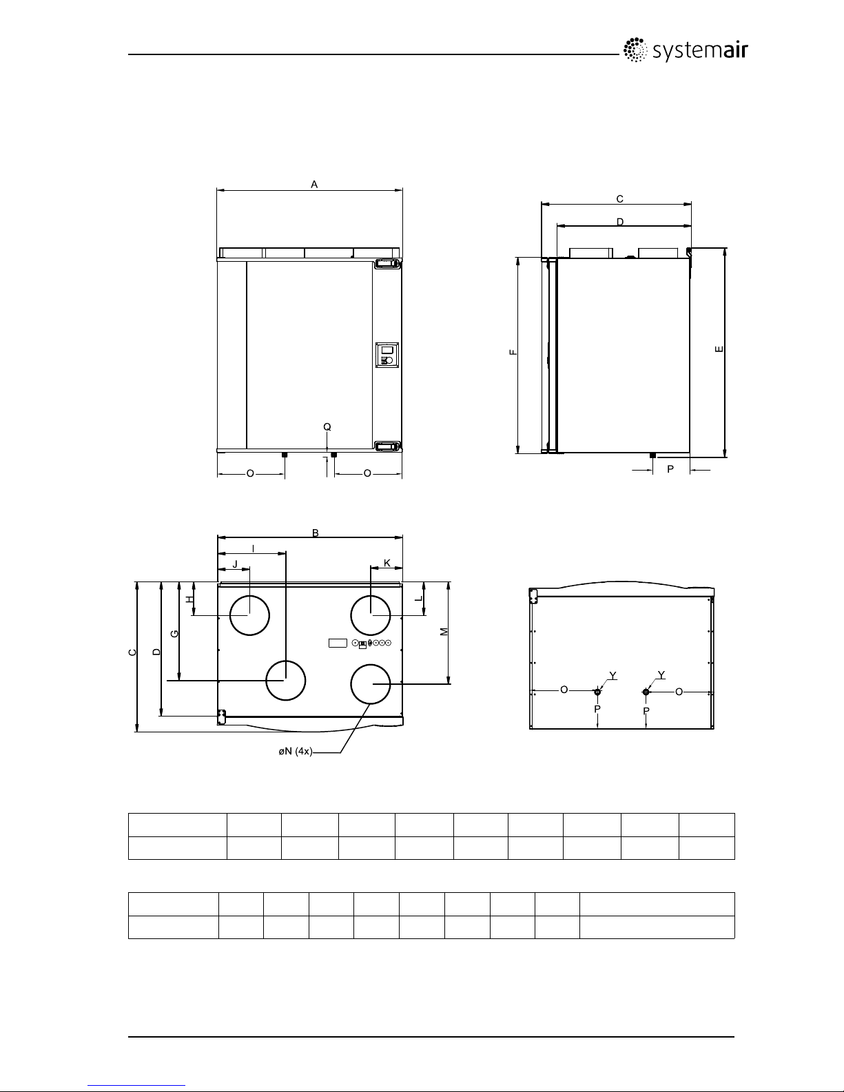
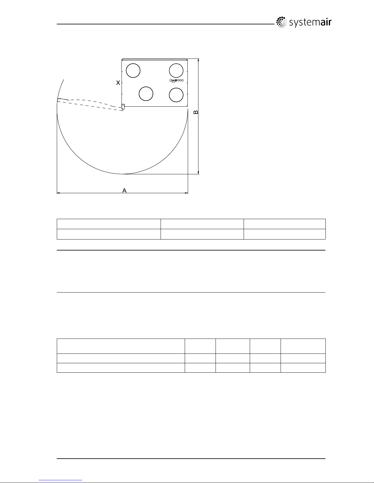
4.2.1DimensionsandWeight
Fig.1Dimensions(mm)andWeight,drawnasarighthandconnectedunit
ModelAB
C
DEF
G
HI
VTC300
762
1
758616553857802406139279
1.Inspectionhatch
ModelJK
L
MN
O
P
QWeight(kg)
VTC300
1311311394211602791521772
Y:½″outerthread
SAVEVTC300InstallationandService
207232
4
SystemairSverigeAB
Page 7

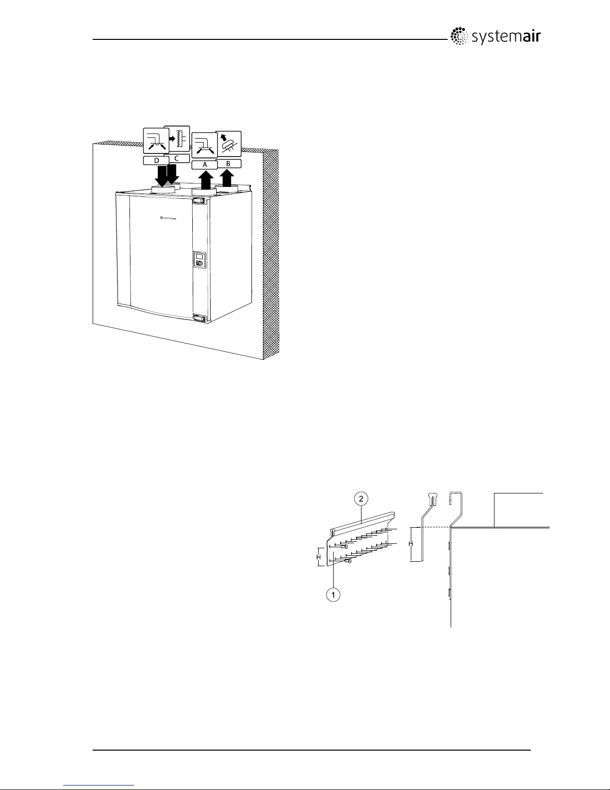
4.2.1.1ConnectionsRightandLeftModels
Fig.2RightandLeftmodels
PositionDescription
R
Righthandmodel(Supplyairconnectionandcontrolpanelissituatedon
therighthandsideoftheunitviewedfromthefront)
L
Lefthandmodel(Supplyairconnectionandcontrolpanelissituatedonthe
lefthandsideoftheunitviewedfromthefront)
Table1:Symboldescription
Symbol
Description
A
Supplyair
BExhaustair
COutdoorair
DExtractair
SAVEVTC300InstallationandService
207232
5
SystemairSverigeAB
Page 8
4.2.2RequiredSpace
Fig.3Spacerequired
ModelAB
VTC300
15071332
Note:
DonotplacethesidemarkedX(gure3)tooclosetoasidewall(distancetosidewallmustbeatleast
150mm).Makesurethattheinspectiondoorcanbeopenedsufcientlytoalloweasymaintenanceand
changingoflters.Ifnecessarytheinspectiondoorcanberemovedcompletely(see“Usermanual”
fordetails).
4.2.3Powerconsumptionandfusesize
Table2:PowerConsumption
Model
Fans(W)Heater(W)Total(W)Fuse(mains)
(A)
VTC300
170
–
17010
VTC300withreheater
1701700187010
4.3Transportandstorage
TheSAVEVTC300shouldbestoredandtransportedinsuchawaythatitisprotectedagainstphysical
damagethatcanharmpanelsetc.Itshouldbecoveredsodust,rainandsnowcannotenteranddamage
theunitanditscomponents.
Theapplianceisdeliveredinonepiececontainingallnecessarycomponents,wrappedinplasticona
palletforeasytransportation.
SAVEVTC300InstallationandService
207232
6
SystemairSverigeAB
Page 9
5Installation
Thissectiondescribeshowtoinstalltheunitcorrectly.T oensureaproperandfailfreeoperationitis
importantthattheunitisinstalledaccordingtotheseinstructions.
5.1Unpacking
Verifythatallorderedequipmentaredeliveredbeforestartingtheinstallation.Anydiscrepanciesfromthe
orderedequipmentmustbereportedtothesupplierofSystemairproducts.
5.2Where/howtoinstall
SAVEVTC300aremeantforindoorinstallationinaheatedspace.Mounttheunitonaverticalat
surface.It’simportantthattheunitiscompletelylevelledbeforeitisputintooperation.
Placetheunitpreferablyinaseparateroom(e.g.storage,laundryroomorsimilar).
Whenchoosingthelocationitshouldbekeptinmindthattheunitrequiresmaintenanceregularlyand
thattheinspectiondoorshouldbeeasilyaccessible.Leavefreespaceforopeningthedoorandfor
takingoutthemaincomponents(gure3).
Theoutdoorairintakeofthebuildingshouldifpossiblebeputinthenorthernoreasternsideofthebuilding
andawayfromotherexhaustoutletslikekitchenfanexhaustsorlaundryroomoutlets.
SAVEVTC300InstallationandService
207232
7
SystemairSverigeAB
Page 10
5.3InstallingtheUnit
Theunitmustbeinstalledinthefollowingposition(gure4).Itisimportantthattheunitiscompletely
verticalinorderforthecondensationdrainagetoworkproperly.
Fig.4Installationposition(righthandunit)
5.3.1InstallationProcedureSAVEVTC300
1
Preparethesurfacewheretheunitistobemounted.Makesurethatthesurfaceisat,levelledandthat
itsupportstheweightoftheunit.Performtheinstallationinaccordancewithlocalrulesandregulations.
2
Fitthemountingbracket(pos.1)withtheanti
vibrationpad(pos.2)tothewallwithenclosed
screws.Useappropriateholestoscrewthe
bracketrmlytothewall.Bottomsideofbracket
shouldbe40mm(H)belowtopofunitposition.
SAVEVTC300InstallationandService
207232
8
SystemairSverigeAB
Page 11

3
Lifttheunitinplace
Warning
Bewareofsharpedgesduringmountingand
maintenance.Useprotectivegloves
Note:
Assurethattheunitiscompletelyverticalonce
mountedonthewall.Theunitmustnotbetipping
forwardinorderforthecondensationdrainageto
function.
4
Connectthecondensatedrainagetothe2drain
plugsinthebottomoftheunit.Makesuretouse
correctdraintrapsonbothconnections.Theheight
(H)mustbeatleast60mm.Draintrapsarenot
includedondeliveryandcannotbeobtainedfrom
Systemair.
5
Connecttheunittotheductsystem.Makesurethatallnecessaryaccessoriesareusedtocreatea
functionalventilationsolution.
Warning
Theinstallationoftheunitandcompleteventilationsystemmustbeperformedbyanauthorized
installerandinaccordancewithlocalrulesandregulations.
6
Connecttheunitelectricallytothemainswiththeenclosedplugandcheckthatitstartsupcorrectly.
SAVEVTC300InstallationandService
207232
9
SystemairSverigeAB
Page 12
5.3.2ElectricalConnections
TheSAVEVTC300iswiredinternallyfromfactory.Theelectricalconnectionboxcanbefoundinthe
supplyairfancompartment.Thetopcoverplateisremovedbyremoving2screwsinthelowerfrontedge
ofthecoverplate(gure5).
Allexternalconnectionstopossibleaccessoriesaremadetoterminalsonthemainprintcard(chapter
5.3.2.2).
Fig.5Openingtheelectricalconnectionbox
Danger
•MakesurethattheMainssupplytotheunitisdisconnectedbeforeperforminganymaintenanceor
electricalwork!
•Allelectricalconnectionsmustbecarriedoutbyanauthorizedinstallerandinaccordancewith
localrulesandregulations.
5.3.2.1Printcardlayout
TheSAVEVTC300isequippedwithbuilt-inregulationandinternalwiring.
Thegureshowstheprintcard.Seewiringdiagramformoreinformation.
SAVEVTC300InstallationandService
207232
10
SystemairSverigeAB
Page 13
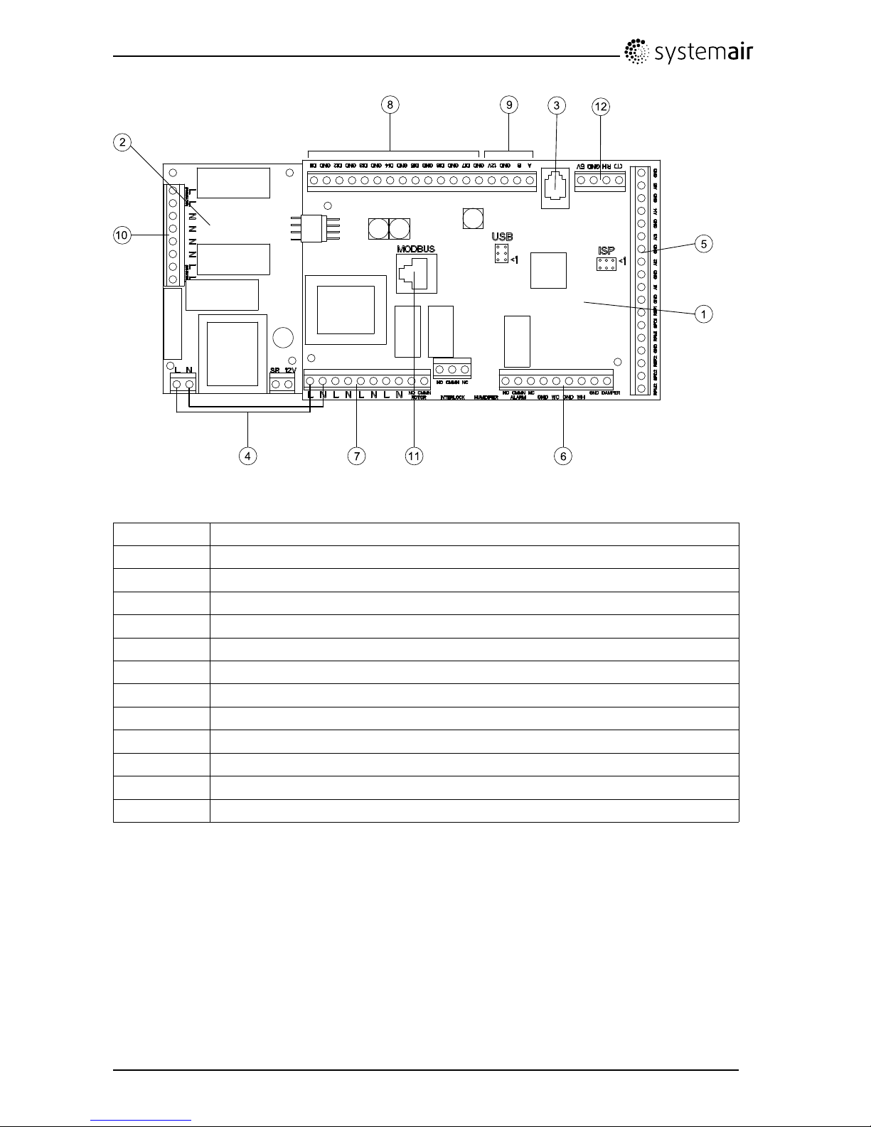
Fig.6Printcard
PositionDescription
1Mainprintcard
2
Printcardforelectricalheater
3
Connectiontoexternalcontrolpanel(connectedtounitcasing)
4Mainssupplyconnectionbetweenmainprintcardandelectricalheaterprintcard
5
TerminalsforAI1–5(tempsensors)andmotorcontrol
6
Terminalsforexternalconnections
7
Terminalsformainssupplyconnections
8
Terminalsfordigitalinputs(DI1–7)
9
Terminalsforinternalcontrolpanel.
10
Terminalsforregulatedpowersupplytoelectricalheater
11
Modbusconnection.See"UsermanualModbus"fordetails.
12
Terminalsforinternalrelativehumiditysensor
SAVEVTC300InstallationandService
207232
11
SystemairSverigeAB
Page 14

5.3.2.2Externalconnectionsontheprintcard
Connectionterminalsforexternalequipmentcanbefoundonthemainprintcardinsidetheelectrical
connectionbox.
Fig.7Externalconnectionsontheprintcard
PositionDescriptionRemark
1
Outdoor/exhaustairdamperNormallyopen,230V1~,max0,1A/
24VAC1A
2
Outdoor/exhaustairdamperReference
3
Outdoor/exhaustairdamperNormallyclosed,230V1~,max0,1A/
24VAC1A
4
Sumalarm
Normallyopen,24V ,max1A
5
SumalarmReference
6
Sumalarm
Normallyclosed,24V ,max1A
7
GNDReference
8
Watercoolercontrolsignal(AO2)0–10VDC
9
GNDReference
10
Waterheatercontrolsignal(AO1)0–10VDC
11
GNDReference
12
Bypassdamper/Rotorcontrol(AO3)Ifused,0–10VDC
SAVEVTC300InstallationandService
207232
12
SystemairSverigeAB
Page 15
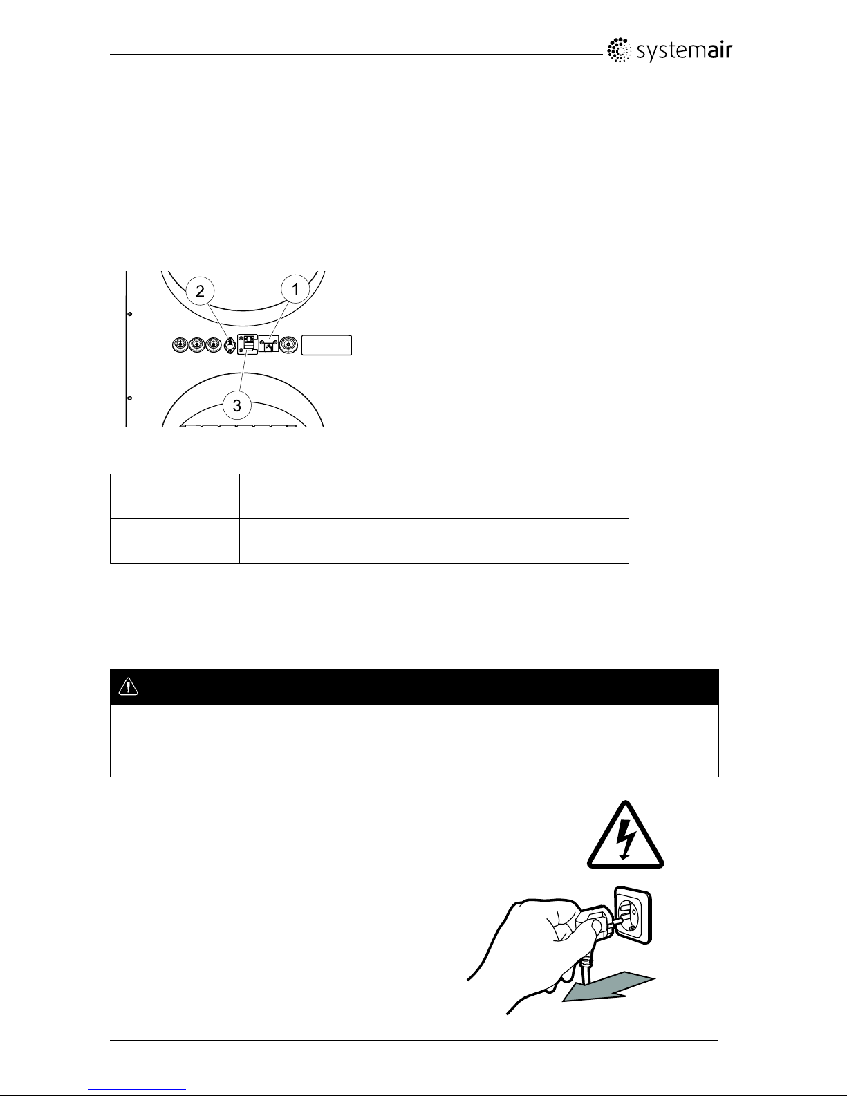
5.3.2.3Externalconnectionsontopoftheunit
Twooftheconnectionsonthemainprintcardarewiredtoplugsontheunitcasing:
•connectiontoanexternalcontrolpanelthroughamodularconnector.
Maximumcablelength:50m.
Cabletype:Flat4–conductorCECPhonecable,orequivalent.
•ExternalModbusconnector.
Maximumcablelength:90mincableduct+10minworkingarea.
Cabletype:LANTCPCat5E4x2XAWG24cable.
•connectiontoDI3withpossibilitytocongurethefanspeedsindividuallythroughapotentialfree
on/offswitch
Fig.8Connectionsontopoftheunitcasing
PositionDescription
1
Connectiontoexternalcontrolpanel
2
ConnectiontoDI3throughanon/offswitch
3ExternalModbusconnection
5.3.3InstallationprocedureElectricalRe-heaterbattery
Anelectricalre-heaterbatterycanbeorderedasanaccessoryandbeinstalledinsidetheunit.Below
instructiondescribestheprocedurefortheinstallationinarighthandunit.
Danger
•MakesurethattheMainssupplytotheunitisdisconnectedbeforeperforminganymaintenanceor
electricalwork!
•Allelectricalmaintenanceworkmustbecarriedoutbyanauthorizedinstallerandinaccordancewith
localrulesandregulations.
1
Disconnecttheunitfromthemainssupply
SAVEVTC300InstallationandService
207232
13
SystemairSverigeAB
Page 16

2
Openthefronthatch
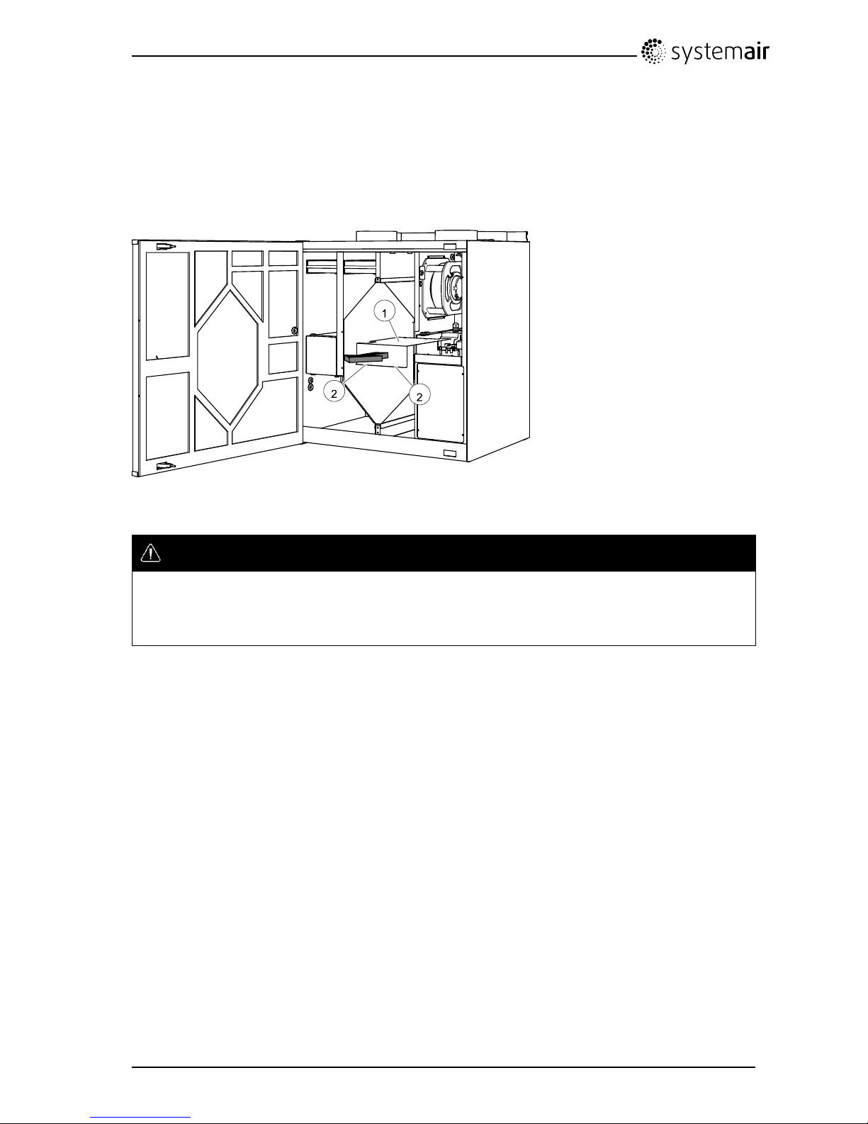
3
Removetheupperplatetotherightoftheheat
exchanger(pos.1)bylooseningthe4screws
(pos.2)
4
Removetheplatecoveringtheelectrical
connectionbox(pos.1)bylooseningthe2screws
inthelowerfrontedgeoftheplate(pos.2)
5
Removethe3screwswiththeblackknobs(pos.
1)fromtheinnercasing.
SAVEVTC300InstallationandService
207232
14
SystemairSverigeAB
Page 17

6
Removethecoveringplate(pos.1)oftheelectrical
re-heaterbylooseningthe3screws(pos.2)
7
Inserttheelectricalre-heaterkit(pos.1)inthe
compartmentnexttothesupplyairfanandfasten
themountingbracketagainsttheinnerwallswith
the3blackknobscrews.
8
Leadthegray4leadcable,containingthewiring
forthemainssupplyandemergencythermostat
(ET),andtheblack2leadOTsensorcablethrough
thepreparedleadthrough’s(pos.1)situated
intheplateseparatingthere-heaterandmotor
compartments.The2cablesarethenleadthrough
thepreparedleadthrough’smarkedbypos.2in
theillustration.
9
Fastenthere-heatercoverplatewiththe4preparedscrewsasillustratedinstepno.6.
10
Continuewithfasteningthere-heaterprintcard
(pos.1)ontheprepareddistances(pos.2)next
tothemainprintcardwiththe4enclosedscrews.
Connectittothemainprintcardbytheuseofthe
preparedconnectionsonthesideofthe2circuit
boards.
SAVEVTC300InstallationandService
207232
15
SystemairSverigeAB
Page 18

11
Connecttheblueandbrowncables(pos.1)to
thefreeL/Nterminalsonthemainprintcard.See
wiringdiagramfordetailedinformation.
12
Connectthewiresinthe4leadgraycable(pos.
1)tomainssupply(brownandbluewire)and
theterminalfortheemergencythermostat(black
andgraywire).Seewiringdiagramfordetailed
information.
13
Connectthewiresinthe2leadblacksensorcable
(OT)toterminalsonthemainprintcard(pos.2).
Seewiringdiagramfordetailedinformation.
SAVEVTC300InstallationandService
207232
16
SystemairSverigeAB
Page 19

14
Putbackthecoverplate(pos.1)andtheplate
(pos.2)andfastenthemwiththeenclosedscrews
15
Turnthepowerbackonandstartthesoftwarecongurationinthedisplayaccordingtobelowprocedure
(chapter7.1).
Aftercompletedinstallationoftheelectricalre-heaterbatterytheunitlooksasdescribedinbelow
illustration(gure9).
Fig.9Installedelectricalre-heater
PositionDescription
1
Electricalre-heaterbatteryfrontplate
2Resetbuttonemergencythermostat
Note:
Afterthere-heaterbatteryhasbeeninstalledandconnectedproperly,applythe2typelabelsbelongingto
theelectricalre-heaterbatterynexttothelabelsoftheunit.Therstlabelisplacednexttotheunitlabel
situatedontheinnerlowerframeofthecasingbehindtheinspectionhatch.Thesecondlabelisplaced
nexttotheunitlabelsituatedontopoftheunitnexttotheductconnections.
SAVEVTC300InstallationandService
207232
17
SystemairSverigeAB
Page 20

6Operation
6.1Controlpanel
Connecttheunitelectricallytothemainswiththeenclosedplugandcheckthatitstartsupcorrectly.
Thecontrolpanelisusedtomakethenecessaryadjustments.
Anexternalcontrolpanelcanbeconnectedonthetopoftheunit.
Theillustrationbelowshowsthecontrolpanelwithashortdescription.
Fig.10Controlpanel
PositionDescriptionExplanation
1Display
Showssymbols,menusandsettings
2
SELECTIONknob
Movethroughthemenulistsorchangesettingsand
valuesbyturningtheknobleftorright
3ENTERbuttonENTERmenuchoicesorsettingsbypressingthebutton
4RETURNbutton
StepRETURNinthemenulevelsandtoabortaninitiated
parameterchangeandrestoretheoriginalvalueby
pressingthebutton
SAVEVTC300InstallationandService
207232
18
SystemairSverigeAB
Page 21

6.1.1Displaysymbols
Symbol
DescriptionExplanation
Temp
Illustratesthecurrentset-pointforsupplyairtemperature
(fromcompletelyemptytolledsymbol).
TurntheSELECTIONknobtochoosetemperature.
PressENTERtosavethesetting.
AirowIllustratesthecurrentairow.Theairowcanbeset
manuallyin5steps:Off,Low,Nom,HighandAuto.
TurntheSELECTIONknobtochooseairow.
PressENTERtosavethesetting.
A.Ventilationoff.
1
B.Lowventilation:Canbeusedwhenleavingthe
buildingforalongerperiod
C.Nominalventilation:Willgiverequiredairchange
undernormalconditions.
D.Maximumventilation:T oincreasetheairowif
necessary.
E.Autoventilation:Willregulateafterthepre-settingfor
thedemandcontrolsettings.
Service
PressENTERtoaccesstheservicemenu.
AlarmPressENTERtoaccessthealarmlist.
1.ThefancanbesettoOFFbyactivatingmanualfanstop.Seeservicemenudescriptionunderfunctions.
Important
Itisnotrecommendedtoactivatemanualfanstop(setfantoOFF)instandardhouseholds.Ifmanualfan
stopisactivated,theunitshouldbeprovidedwithdampersinexhaustandfreshairductstoavoidcold
draughtandriskofcondensationwhentheunithasbeenstopped.
SAVEVTC300InstallationandService
207232
19
SystemairSverigeAB
Page 22
6.2Servicemenuoverview
Entertheservicemenubyselectingtheservicesymbolinthedisplay.
MenuLevel1MenuLevel2MenuLevel3Explanation
Service
Password
Password
PasswordXXXX
LockedYES/NO
Entertheservicelevel
bytyping1 1 11.Usethe
SELECTIONknobforeach
digitandconrmwiththe
ENTERbuttonaftereach
setdigit.NOwillunlockthe
systemandallowparameter
changes.
Service
Change
Password
Changepassword
ActualXXXX
NewXXXX
ConfirmXXXX
Setnewpasswordif
necessary.
Incasethenewpassword
wouldbeforgottenor
misplaced,it’sstillpossible
toentertheservicelevelby
writing8642.Thisoverrides
theearliersetpassword.
Service
Filterperiod
Filterperiod
Timeto
replace:
12month
ResetNO/YES
Showsselectedtimeinterval
betweenlterchange.
SetResetofthelterperiod
toYESaftercompletedlter
change.
Settimebetweenlter
changes.
Service
Time/Date
Time/Date
YY/MM/DD
Date:12/09/12
Time:10:00
Weekday:Sat
Showscurrentsetdateand
time.
SetCorrectdateandtime.
Service
Summer/Winter
Summer/Winter
Autotime
change?
YES/NO
Usethisdialogframe
tocongureautomatic
summertime/wintertime
change-over.Timewill
automaticallychange
betweensummertimeand
wintertimeaccordingto
Europeanstandard,based
onGreenwichtimezone.
DefaultvalueYES.
SetYESorNO
SAVEVTC300InstallationandService
207232
20
SystemairSverigeAB
Page 23

MenuLevel1MenuLevel2MenuLevel3Explanation
Service
Ext/ForceRun
Ext/ForceRun
Minutes:0
Airflow:
Nominal
Usethisdialogueframeto
programextendedtimeyou
wanttheunittoworkunder
operationconditionsother
thandeterminedbytheweek
schedule.
Showssettimefor
extended/forcedrunning.
ShowsSetairow.
Setthetimethattheunitisto
runinextended/forcedmode.
Valuerange:0–240minutes.
Settheairowforthismode.
ChoosebetweenLow,Nom
orHigh.
Defaultvalue:Nom.
Service
Weekprogram
Weekprogram
Weekprogram
Weekprogram
Day:MON
Per1:07:0016:00
Per2:00:0000:00
Programhowyouwantthe
unittooperateaccording
totheweekschedule.It’s
possibletoset2periodsper
day.
Setweekdayandtime
intervalforthetimeyouwant
theunittobeinONmode.
Weekprogram
Airflow
Airflow
Onlevel:
low/nom/high/auto
Offlevel:
off/low/nom/high
Usethisdialogueframeto
determinetheONandOFF
functionforthefansinthe
weekschedule.
SetONlevel.
ChoosebetweenLow,Nom,
HighorAuto.
Defaultvalue:Nom
SetOFFlevel.
ChoosebetweenOFF ,Low,
NomorHigh.
Defaultvalue:Low.
Service
Airflowlog
Airflowlog
Level:1–5
Reset:NO/YES
SF:140/140
EF:140/140
Usethisdialogueframe
toseehowthefanshave
operatedduringthetime(h)
theyhavebeenactive.
Theairowareshownin5
differentlevels:
•Level1:0%
•Level2:1–29%
•Level3:30–44%
•Level4:45–59%
•Level5:60–100%
Choosebetweenthelevels
toseethetimeinhoursthe
fanshavebeenactiveinthe
differentlevels.
SAVEVTC300InstallationandService
207232
21
SystemairSverigeAB
Page 24

MenuLevel1MenuLevel2MenuLevel3Explanation
ResetY esresetstheSFand
EFtimeintheleftcolumnfor
alllevels.Therightcolumn
continuestocountaheadand
cannotbereset.
Note:
Factoryreset(see
Functions–>Factory
reset)willnotaffectthis
function
Service
Functions
Functions
Heater/Cooler
Heater/Cooler
Preheater:YES/NO
Reheater:
None/Electrical/Water/Other
Cooler:None/Water
Usethisdialogueframeto
setuptheunitforheating
and/orcooling.
SetYEStoactivate
preheater.Defaultsettingis
NO.
SetRe-heatertoNone,
Electrical,WaterorOther.
Note:
IfreheaterissettoOther,
externalheaterisonly
controlledbyAO1(0–10V).
Overheatorfrostprotection
isnotavailable.
SetCoolertoNoneorWater.
Functions
Temp.Control
Temp.control
P-band:5°C
I-time:OFF
Output:0–100%
Usethisdialogframeto
adjustthesettingsofsupply
airtemperaturecontroller.
Settheproportionalband
(P-band)rangeforPI
controller.Defaultvalue5°C.
Setintegraltime(I-time)
rangeforPIcontroller.
DefaultvalueOff.
Showsoutputsignal
presentedforthesupply
airtemperaturecontroller.
SAVEVTC300InstallationandService
207232
22
SystemairSverigeAB
Page 25

MenuLevel1MenuLevel2MenuLevel3Explanation
Functions
Preheater
Pre-Heater
PreheaterSp:-30–
0°C)
P-band:5°C
I-time:OFF
Output:Auto(xx%)/
Man(Off/On)
Usethisdialogframeto
congurepre-heaterfunction.
Congurethesetpoint
setting.Defaultvalueis
dependantonsystemtype.
Incounterowunitssetpoint
isnotadjustable.
Settheproportionalband
(P-band)rangeforPI
controller.Defaultvalue5°C.
Setintegraltime(I-time)
rangeforPIcontroller.
DefaultvalueOff.
SetoutputtoAutoorMan.
DefaultsettingisAuto.Actual
controlleroutputsignalis
presentedinautomode.
SelectingMan,enablesthe
usertomanuallycontrol
outputofthepreheater
(On/Off).
Functions
Frostprotection
Frostprotection
Alarmlimit:7°C
Showscurrentsetfrost
protectionalarmlimitin°Cfor
theinstalledwatercoil.
SetAlarmlimitin°C.
Defaultvalue:7°C.
Functions
Fancontrol
Fancontrol
Airflow
%
Only“%”isoption(default)
Fancontrol
Airflowunit
Airflowunit
%
Only“%”isoption(default)
Demandcontrol
DemandcontrolCO2/
RH
Setpoint0ppm/0%RH
P-Band100ppm/10%RH
I-TimeOFF
Itispossiblecontrolthe
indoorairqualityusing
RH(Relativehumidity)
orCO2(Carbondioxide)
sensor/sensors.Default
setpointsettingisOff.
(0%/0ppm).
Bothtypesshouldbeable
touseatthesametime,
meaning2PIcontrollers.
Whendemandcontrol
setpointiscongured,fans
settoautomodeandregulate
againstthesetpoint.The
fansymbolshouldhavethe
middleareaempty,andthe
outerandinnerlled.It
shouldnotbepossibleto
changeeither.
SAVEVTC300InstallationandService
207232
23
SystemairSverigeAB
Page 26

MenuLevel1MenuLevel2MenuLevel3Explanation
Fancontrol
Airflow
Airflow
%
Nom
High
Low
EF
50
100
25
SF
50
100
25
Usethisdialogueframeto
settheairowin%.The
airowcanbesetindividually
foreachfan
EF:Extractfan,
SF:Supplyfan
SettheairowforEFandSF
foreachstep(Low,Nom,and
High.
Functions
Manualfanstop
Manualfanstop
Allowmanualfan
stopY/N
Setifitshouldbepossible
toturnoffthefansintheunit
manuallyfromthecontrol
panel.
ChosebetweenYandN.
IfYisselectedthefanscan
beturnedoffbyturningthe
SELECTIONknobtoempty
fan
Functions
Analoginput
Analoginput
1:SS20.0
2:ETS23.0
3:Unused
4:Unused/OT/FPS
20.0
5:OS10.5
6:RH0%
Showsanalogueinputsfrom
activetemperaturesensors.
SS:Supplyairtempsensor.
ETS:Extractairtempsensor.
FPS:Frostprotectionsensor.
OS:Outdoorairtempsensor.
OT:Overheatprotection
sensor.
RH:Relativehumiditysensor .
Functions
Analogoutput
Analogoutput
A01auto/man/off
A02auto/man/off
A03auto/man/off
Showscurrentanalogue
outputsin0–10Vtohot/cold
wateractuatororelectrical
re-heaterandrotordrive/
bypassdamper.
SetAO1(Analogueoutput
tohotwateractuatoror
electricalre-heater)toauto,
manoroff.
Defaultvalue:auto.
SetAO2(Analogueoutputto
coldwateractuator)toauto,
manoroff.
Defaultvalue:auto.
SetAO3(Analogueoutputto
rotordriveorbypassdamper)
toautoorman.Defaultis
auto.Selectingmanenables
theusertomanuallycontrol
theactuator/damperwitha
0–10Vsignal.0Vcompletely
closedand10Vcompletely
openedactuator/bypass
damper.
SAVEVTC300InstallationandService
207232
24
SystemairSverigeAB
Page 27

MenuLevel1MenuLevel2MenuLevel3Explanation
Functions
Digitalinput
Digitalinput
DI1ON/OFF
DI2ON/OFF
DI3ON/OFF
DI4ON/OFF
DI5ON/OFF
DI6ON/OFF
DI7ON/OFF
Showscurrentstatusofthe
digitalinputsONorOFF
DI1:Fanconguration
DI2:Fanconguration
DI3:Fanconguration
DI4:Heaterdeactivated
DI5:Extended/forcedrunning
DI6forrotatingheat
exchanger:
Rotorsensor
DI6forcounterowheat
exchanger:
Bypassdamperlimitswitch
DI7:Home/leave
Functions
ConfigDI1–3
ConfigDI1–3DI:1–3
SF:highEF:high
Polarity:N.O/N.C
Delay:Off–240s
DI1–3arefreetousefor
anypurposeandhavea
differentpriority,DI1being
thehighest.DI1–3havea
higherprioritythanDI5.
Itispossibletoinvertinput
function.
SetDI1–3tobenormally
open(N.O)ornormally
closed(N.C).Defaultsetting
N.O.
Itisalsopossibletosethow
youwantthefanstoreactto
3differentdigitalinputswhen
theyareswitchedon.
Potentialfreeswitchesneed
tobeconnectedphysically
toterminalsonthemain
printcardtoobtainthe
differentfunctions.Seethe
wiringdiagramformore
information.
Setthesupplyairfan(SF)
andextractairfan(EF)
individuallytooff,low,nomor
highfordigitalinputs1–3
Setapredenedoffdelay
fortheinputsignal.System
willbeintheONstatefor
predenedperiodoraslong
asDIisactivatedandperiod
issetto0.Countingdown
forthepredenedperiod
startswhenDIfunctionis
deactivated.Defaultvalueis
0sec.
SAVEVTC300InstallationandService
207232
25
SystemairSverigeAB
Page 28

MenuLevel1MenuLevel2MenuLevel3Explanation
Functions
DI4–7
DI4–7
4Stopheat
5Extrun
6Damper/Rotor
7Home/Leave
DI4–7aredefaultsetfrom
factoryandcan’tbechanged
bytheuser .Belowfollows
ashortdescriptionofeach
function.
DI4:Makesitpossible
todisabletheelectrical
re-heater.Activated
inputmeansthatthe
electrical/otherre-heater
isdeactivated.
DI5:Activatethe
Extended/forcedrunning
function.Thefunction
overridescurrentsetairow
settingsandrunsaccording
tothesettingsinService->
Ext/Forcerun.Choose
betweenLow,Nomand
Highforthisfunction.The
inputiscalculatedbased
onthesignalsfroman
impulse-switch.Ifastandard
switchisused,thecountdown
ofthesettimestartswhen
theswitchisswitchedoff.
DI6forrotatingheat
exchanger:
Rotorsensor.Usedbythe
systemtomonitortherotor
rotation.
DI6forcounterowheat
exchanger:
Bypassdamperlimitswitch.
Usedbythesystemtodetect
thedamperposition.
DI7:Activateslowenergy
supportcontrol.Heat
exchangeroperatingby
theadjustedsetpointvalue
andaactivere-heaterhas
supportcontrolforthelowest
setpoint.(12°C)
Thefunctionisusedwhen
thebuildingisuninhabitedfor
alongerperiod.
Itisrecommendedtoconnect
DI7andDI1orDI3inparallel.
IfDI7isactivated,setthe
fansspeedtomin.Airow
settingsaredonewhen
conguringDI1/DI3.
SAVEVTC300InstallationandService
207232
26
SystemairSverigeAB
Page 29

MenuLevel1MenuLevel2MenuLevel3Explanation
Functions
Digitaloutput
Digitaloutput
1:SF67%
2:EF67%
3:RotON/OFF
4:ALARMY/N
5:DmpY/N
6:HeaterY/N
ShowsThecurrentstatus
ofdigitaloutputs1–6(the
settingsinthecolumntothe
leftareexamples).
1:SF67%:Currentset
speedofthesupplyairfan
(shownaspercentageofthe
maximumspeed).
2:EF67%Currentset
speedoftheextractairfan
(shownaspercentageofthe
maximumspeed).
3:Showsiftherotorisactive
ornot.Unusedforunitwith
counterowheatexchanger.
4:AlarmY/N:Indicatesifthe
sum.alarmisactiveornot
5:DmpOFF:
Outdoor/exhaustairdamper
isonoroff.
6:HeaterY/N:Indicatesifthe
electricalre-heaterisactive
ornot.
External
sensors
Externalsensors
CO2:0ppm—
RH:0%—
Lastvalidvalueispresented
fortheboundedsensors.
Highestactualsensor
signalpresentedvia
–/modbus/wireless.
Unboundsensorpresented
as–(none).
Modbussensorshaspriority
overwirelesssensors.
Functions
ExternalDI
ExternalDI
ActiveWireless:
DI1/..DI20
Assignto:
—/DI-5/DI7
ExternalDImenuonly
availableifoneorseveral
“Inputmodules”areboundto
thesystem.Activewireless
DI1-20isdependedonactual
nodefor“Inputmodule”.
Nodeshownin“Wireless”
menuwhichnode
representingDImodule
inputs.
Eg.
Node1type:DI.Active
wirelessDI1andDI2
Node2type:DI.Active
wirelessDI3andDI4
Node10type:DI.Active
wirelessDI19andDI20
ActivewirelessDI1-20are
availabletoassigntoDI1-5
SAVEVTC300InstallationandService
207232
27
SystemairSverigeAB
Page 30

MenuLevel1MenuLevel2MenuLevel3Explanation
andDI7forthesysteminthe
airhandlingunit.
DI6isnotavailableas
selection,usedbythesystem
intheairhandlingunit.
UnsignedDIisshownas–
(none).
Toresetapreviously
assignedDI,select“–”
andconrmtheselection.
Functions
Wireless
ExternalDI
Note:1Type:None
State:NoNetwork
Data:0
Wirelesssystemstatus.
Node:Showsnumberof
boundwirelessmodule.
Type:None/UI:User
Interface(Controlpanel)/DI:
DigitalInputmodule/CO2:
CO2sensormodule/RH:RH
sensormodule.
State:NoNetwork:No
gatewayconnectedtothe
systemforairhandling
unit/Unbound:Nobonded
module/OK:Successful
bindingofmodule
Data:Theactualvalue
frommodule/Commfail:
Communicationfailure,se
manualforactualmodulefor
troubleshooting.
Toresetallboundnodes,
seeusermanualforGateway
Wireless.
Functions
Defrosting
WhenRHsensorisused:
Defrosting
ModeNormal/Hard/
Soft
AllowunbalanceYES
RHsensor:YES
WhenRHsensorisnot
used:
Defrosting
Mode1–5
AllowunbalanceYES
RHsensor:NO
Usethisdialogueframetoset
howaggressiveyouwantthe
defrostingfunctiontooperate
(seechapter7.2).
SAVEVTC300InstallationandService
207232
28
SystemairSverigeAB
Page 31

MenuLevel1MenuLevel2MenuLevel3Explanation
Functions
Calibration
Calibration
Sensorvalue:0%
Adjustedvalue:0%
Confirm:YES/NO
Usethisdialogueframe
tocalibrateinternalRH
sensorforanydeviationsif
necessary.
Showscurrentinputsignal
valueofRHsensor.
SetadjustedvalueforRH
sensor.
Adjustedvaluemustbe
conrmed.
SetYEStoconrmchanges.
Functions
Modbus
Modbus
Settings
Settings
Address1
Baud19200
ParityNone
InformationaboutModbus
communicationandvariables
canbefoundintheModbus
usermanualforresidential
unitsintheonlinecatalogue
at
www.systemair.com.
Modbus
Gateway
Gateway
StateNot
present/...
Showscurrentstatusof
communication.
Functions
Factoryreset
Factoryreset
Reallyreset?
YES/NO
Usethisdialogueframeto
returntofactorysettings.
SetYESorNO
Note:
Thiswilleraseallyour
personalsettingsthathave
beendonefortheunit.
Service
Language
Language
Language
ENGLISH
Usethisdialogueframeto
returntoselectyourlocal
language.
SetLanguagebyturningthe
SELECTIONknob.
Service
Versions
VersionVTC300
Appl.
Boot
CD
xxx
xxx
EC
xxx
xxx
Showscurrentsoftware
versions
Note:
Thesoftwareversionsare
justanexampleandmay
differinaspecicunit.
SAVEVTC300InstallationandService
207232
29
SystemairSverigeAB
Page 32

MenuLevel1MenuLevel2MenuLevel3Explanation
Firmware Service
Firmware
Unit
Gateway
Update
CD
xxx
xxx
YES
EC
xxx
xxx
/NO
Usethisdialogueframeto
updatermware.
SetYESorNO.
Showscurrentversionofthe
unitandZ-waveGateway.
Service
Alarms
Alarms
Fan
Frost
Bypass
Rot
PbFail
Temp
Filter
LowSS
Defrost
RH
Showsthealarmsthathave
beentriggered.Seealarm
list(chapter9.3.1)
6.3Settingthetemperature
Thesupplyairtemperatureissetmanuallyinstepsof1Kinthemainmenudisplaybychoosingthe
temperaturesymbol.
Ifanelectricalre-heaterisinstalledthetemperaturesetpointsare:
12-22°C.Forinstalledwaterre-heaterthesetpointsare:12-40°C.
Ifthere-heaterisdeactivated,thetemperaturestepsare:
15-19°C.Defaultvalue:15.0°C.
Eachtemperaturestepisillustratedbyincreasingthellingofthetemperaturesymbolandthetemperature
isshowninthedisplay
Anunlledtemperaturesymbolwillactivatemanualsummermode.Seechapter6.5
6.4Manualsettingofairow
Itispossible,atanytime,tomanuallysettheairowinthemainmenudisplay.Bychoosingthefansymbol
andconrming,itispossibletoincreaseordecreasetheairowin5steps:Off,Low,Nom,HighandAuto.
Bydoingso,youoverridetheprogrammedweekschedulefortheunituntiltheendofthepresenttime
periodintheweekprogram(chapter7.3).
SAVEVTC300InstallationandService
207232
30
SystemairSverigeAB
Page 33

Warning
Itisnotrecommendedtoactivatemanualfanstop(setfantoOFF)instandardhouseholds.Ifmanual
fanstopisactivated,theunitshouldbeprovidedwithdampersinexhaustandfreshairductstoavoid
colddraughtandriskofcondensationwhentheunithasbeenstopped.
ThefancanbesettoOFFbyactivatingmanualfanstop.SeetheInstallationandServicemanual,
chapterServicemenuoverview:Manualfanstop.
6.5Manualandautomaticsummermode
Manualsummermodeoccursifnotemperaturestepisselected.Thetemperaturesymbolonthemain
menuisthencompletelyempty .
Iftheelectricalre-heaterisactivated,itwillswitchoffduringmanualsummermode.Manualsummer
modegoesautomaticallytostep1(setpoint12°C)aftertwominutesifthesupplyairtemperatureis
+5°Corbelow.
Ifawaterheaterbatteryisinstalledandactivated,themanualsummermodegoesautomaticallytostep1
(setpoint12°C)iftheoutdoorairorsupplyairtemperatureis+5°Corbelow.
Theunitwillautomaticallyalternatebetweenwinteroperationwithheatrecoveryandsummeroperation
withoutheatrecovery .
6.6Coolrecovery
Iftheoutdoorairiswarmerthantheextractairandthesupplyairisabovethesetpoint,coolrecovery
occurs.Thisconditionblockstheheatregulationprocess.
SAVEVTC300InstallationandService
207232
31
SystemairSverigeAB
Page 34

7Commissioning
7.1Startupwizard
TheStartupWizardisastep-by-stepcongurationtoolthatstartsautomaticallywhentheSAVEVTC
300isstartedforthersttimeorwhen:
•afactoryresetisperformed
•anewprintcardisinstalled(sparepart)
Inthiscasetheunittypemustbeentered(SAVEVTC300)
TheairowintheStartupwizardcanbesetbypercentage(Airflow%)withtheFancontrol.
7.1.1Procedure
1.TurntheSELECTIONknobtochooselanguageandpressENTER
Languages
LanguageENGLISH
2.Chooseunittype,thischoiceisonlypresentifanewprintcardis
installed(sparepart)orwhenafactoryresetisperformed.
Type
SAVEVTC300
3.Setdateandtime
Time/DateYY/MM/DD
Date:12/09/12
Time:10:00
Weekday:Sat
4.Selectheater:None/Electrical/Water/Other
Note:
Thischoiceisavailableonlyafterafactoryreset,seechapter7.1.2,or
whenanewprintcardisinstalled.
Heater
Reheater:None/Electrical/Water/Other
Airflow
%
EF
SF
Nom
5050
High100100
5.Fancontrol.
TurntheSELECTIONknobtoselectpercentage(%)fancontroland
pressENTER.
HereitispossibletochangetheNominal/High/LowairowontheExtract
airfan(EF)andSupplyairfan(SF).Airowin%.
Whensettingsaredone,pressENTER.
Low
2525
SAVEVTC300InstallationandService
207232
32
SystemairSverigeAB
Page 35

7.1.2PerformFactoryreset
Howtoperformafactoryresetifnecessary:
1.Entertheservicemenubyselectingtheservice
symbolinthedisplayandpressENTER.
2.Gotopasswordandenterthepassword,
default11 1 1
UsetheSELECTIONknobforeachdigitand
conrmwiththeENTERbuttonaftereachsetdigit
andchooseNOforthesystemnotbelocked.
Password
PasswordXXXX
LockedYES/NO
3.GotoFunctionsandselectFactoryReset
Functions
Factoryreset
4.TurntheSELECTIONknobsoYESisshown
andpressENTER.
Factoryreset
Reallyreset?YES/NO
5.ACCEPTEDisshowninthedisplaywindow
ACCEPTED
6.TheStartupWizardstartsafterapproximately
10seconds
SAVEVTC300InstallationandService
207232
33
SystemairSverigeAB
Page 36

7.2Defrostsettings
Theunitisequippedwithanautomaticdefrostfunctionthatisactivatedwhenthereisriskoficinginthe
areaaroundtheheatexchanger.Thesettingshownintable3determineshowaggressivethedefrosting
willbe.DefaultfactorydefrostmodesettingisNormal.
Ifrelativehumiditysensoriscongurednottobeusedfordefrosting,thendefrostinglevelshavetobe
selectedmanuallybytheuser ,inthatcasedefrostingwillbecontrolledonlybytheoutdoorairtemperature
sensor.Thesettingsareshownintable4.
Note:
Theheatexchangershouldwithstandlowoutdoortemperatures,butinthosecaseswhereicingcan
occurpleasebeawareofthatthedefrostsettingwillgenerateanunderpressureinthebuilding.Using
areplace,beawarethatthereisapossibleriskofsmokebeingextractedintothelivingareasdueto
underpressureifdefrostingisactivated.
Table3:Defrostmodes
Defrostmode
Description
SoftDryareas,suchaswarehousebuildingswithfewpeopleorindustrial
buildingsthatdon’tusewaterintheirproductionprocess.
NormalApartmentsorhouseswithnormalhumidity
1
HardBuildingswithveryhighhumiditylevel.
1.Innewlyconstructedhousesitmightbenecessarywithahigherdefrostlevelduringtherstwinterperiod.
Table4:Defrostlevels
Defrost
level
Levelofhumidity
Relativehumidity
indoors
1
Description
0
<20%Defrostingisturnedoff.Areaswhererelative
humidityisverylow.
Note:
Thissettingisnotvalidforunitsequippedwith
counterowheatexchangerswhenRHsensor
issetnottobeusedfordefrosting.
1Min
20%-29%
Dryareas,suchaswarehousebuildingswith
fewpeopleorindustrialbuildingsthatdon’tuse
waterintheirproductionprocess.
2Low
30%-40%Ofcebuildings
3Medium
41%-60%
Apartmentsorhouseswithnormalhumidity
2
4High
61%-80%
Apartmentsorhouseswithhighhumidity
5
Extremelyhigh
>80%
Buildingswithveryhighhumiditylevel.
1.Approximatevaluesofrelativehumidityintheextractairatcoldoutdoortemperatures.
2.Innewlyconstructedhousesitmightbenecessarywithahigherdefrostlevelduringtherstwinterperiod.
SAVEVTC300InstallationandService
207232
34
SystemairSverigeAB
Page 37

7.2.1Settingthedefrostlevel
1.Gototheservicemenubyusingthe
SELECTIONknob.
2.Entertheservicelevelbytypingthepassword,
default1111.UsetheSELECTIONknobforeach
digitandconrmwiththeENTERbuttonaftereach
setdigitandchoose"NO"forthesystemnotbe
locked.
Password
PasswordXXXX
LockedYES/NO
3.Goto:Functions
Choose:Defrosting
Functions
Defrosting
4.SetthemodeWhenRHsensorisconguredtobeusedfor
defrostingfunction:
Defrosting
ModeSoft/Normal/Hard
RHsensor:YES
WhenRHsensorisnotconguredtobeused
fordefrostingfunction:
Defrosting
Mode1–5
RHsensor:NO
5.Selectifunbalancedairowsareallowedinthe
buildingduringthedefrostcycle.Choosebetween
YESandNO.DefaultisYES.
AllowunbalanceYES/NO
SAVEVTC300InstallationandService
207232
35
SystemairSverigeAB
Page 38

7.3ProgrammingtheWeekschedule
Settheweekscheduleaccordingtobelowprocedure:
1.Gototheservicemenubyusingthe
SELECTIONknob.
2.Entertheservicelevelbytypingthepassword,
default1111.UsetheSELECTIONknobforeach
digitandconrmwiththeENTERbuttonaftereach
setdigitandchoose"NO"forthesystemnotbe
locked.
Password
PasswordXXXX
LockedYES/NO
3.Goto:Weekprogram
Service
Weekprogram
4.ChooseWeekprogramagain.
Weekprogram
Airflow
5.Setweekdayandtimeyouwanttheunitto
beinONlevel.Twoperiodsperdaycanbe
programmed.Therestofthetimetheunitwillbein
OFFlevel.
Weekprogram
Day:MON
Per1:07:0016:00
Per2:00:0000:00
6.Gobacktothepreviousdialogueframewiththe
RETURNbuttonandgodowntoAirflow.
Weekprogram
Airflow
7.Setwhichairowthefanissupposedtobe
runningintheONlevel,choosebetweenLow,
Nom,HighorAuto.
Setwhichairowthefanissupposedtoberunning
intheOFFlevel,choosebetweenOFF,Low,Nom
orHigh.
Note:
Ifanelectricalre-heaterbatteryisinstalledand
activeandtheunitisshutdownfromthecontrol
panel,forexamplebychoosingOFF.Whenthe
unitisinOFFlevelintheweekprogram,thefans
willcontinuetorunfor3minutes,topreventthe
heaterfromtriggeringtheoverheatprotection
sensor,beforetheystop.
Airflow
Onlevel:low/nom/high/auto
Offlevel:off/low/nom/high
8.StepbackwiththeRETURNbuttonuntilyou
reachthemainmenudisplay
SAVEVTC300InstallationandService
207232
36
SystemairSverigeAB
Page 39

7.4Extrafunctions
Theunitisequippedwithanumberofextraon/offfunctionswhichcanbeactivatedfromexternalon/off
switchesthatcanbeconnectedtothedigitalinputsonthemainprintcard(seewiringdiagram).
Thefollowingpossibilitiesareavailable:
•Digitalinputs1–3:Arefreetobeusedforanypurpose,theyalsohaveadifferentpriority ,DI1being
thehighestandDI3thelowest.DI1–3haveahigherprioritythanDI5.Byconnectingon/offswitches
totheseinputsit’spossibletochoose4(Off/Low/Normal/High)individualairowsettingsinthecontrol
paneldependingonatemporaryneedforthebuilding(forexampleloweringtheextractairairow
whenanopenreplaceisused).Seechapter6.2.
DI3ispreparedandalreadyconnectedinternallyforeasyaccessontheunit.Seechapter5.3.2.3.
Inunitswithabuilt-inbypassforcookerhoodconnection,DI3canbeusedtocontrolexternalcooker
hood.IthastobeconguredasSF=HighandEF=High.
•Digitalinput4:Makesitpossibletodisabletheelectrical/otherre-heater
Activatedinputmeansthattheelectrical/otherre-heaterisdisabled.
•Digitalinput5:ActivatetheExtended/forcedrunningfunctionwithaimpulseswitch.Thefunction
overridescurrentairowsettingsandrunsinforcedmodeaccordingtothesettingsinService->
Ext/Forcerun.ChoosebetweenLow ,NomandHighforthisfunction.
Theinputiscalculatedbasedonthesignalsfromanimpulse-switch.Ifastandardswitchisused,the
countdownofthesettimestartswhentheswitchisswitchedoff.
•Digitalinput6:Controlfortheexchanger,usedbythesystem
•Digitalinput7:Home/leave,switchingonthisactivateslowenergysupportcontrol.Theheat
exchangerisalwaysoperatingaccordingtothesetpointvalue.Isthereare-heateractivateditwill
operateaccordingtothelowestsetpointvalue(12°C).Thefunctionisusedwhenthebuildingis
uninhabitedforalongerperiod.
ItisrecommendedtoconnecteitherofDI1,DI2orDI3inparallelwithDI7.IfDI7isactivated,setthe
fansspeedtomin.AirowsettingsaredonewhenconguringDI1,DI2orDI3.
Seemenuoptionsin“ServicemenuOverview”(chapter6.2).
8Beforestartingthesystem
Whentheinstallationisnished,checkthat:
•Theunitisinstalledinaccordancewiththeinstructions
•Theunitiscorrectlywired
•Outdoorandexhaustairdampersandsilencersareinstalledandthattheductsystemiscorrectly
connectedtotheunit
•Allductsaresufcientlyinsulatedandinstalledaccordingtolocalrulesandregulations
•Outdoorairintakeispositionedwithsufcientdistancetopollutionsources(kitchenventilatorexhaust,
centralvacuumsystemexhaustorsimilar)
•Allexternalequipmentareconnected
•Theunitiscorrectlyconguredandcommissioned
•Theweekscheduleandairowsettingsarecorrectlyprogrammed.
9Service
Note:
Questionsregardingtheunitandtheinstallationareansweredbyyourinstallerorplaceof
purchase!
SAVEVTC300InstallationandService
207232
37
SystemairSverigeAB
Page 40

9.1Warnings
Danger
•Makesurethatthemainssupplytotheunitisdisconnectedbeforeperforminganymaintenanceor
electricalwork!
•Allelectricalconnectionsandmaintenanceworkmustbecarriedoutbyanauthorizedinstallerand
inaccordancewithlocalrulesandregulations.
Warning
•Thesystemshouldoperatecontinuously,andonlybestoppedformaintenance/service
•Althoughthemainssupplytotheunithasbeendisconnectedthereisstillriskforinjuryduetorotating
partsthathavenotcometoacompletestandstill
•Bewareofsharpedgesduringmaintenance.Useprotectivegloves
•Makesurethatltersaremountedintheirplacebeforerunningthesystem
•Thisproductmustonlybeoperatedbyapersonwhichhassuitableknowledgeoreducationwithin
thiseldorcarriedoutwiththesupervisionofasuitablyqualiedperson.
SAVEVTC300InstallationandService
207232
38
SystemairSverigeAB
Page 41

9.2InternalComponents
Fig.11Components
PositionDescription
1Fan,supplyair
2Fan,extractair
3Filter,outdoorair
4Filter,extractair
5
Defrostdamper
1
6
Motor,defrostdamper
7
Coverplate,defrostdamper
8Heatexchanger
9
Condensationtray
10
Condensationdrain
12
Coverplate,electricalconnectionbox
13Printcardwithterminals
14Temperaturesensor,supplyair
15Temperaturesensor,outdoorair
16Temperaturesensor,extractair
17
Fastcouplingsforsupply-andextractairfan
1.Thedampermaynotbeturnedbyhand!
SAVEVTC300InstallationandService
207232
39
SystemairSverigeAB
Page 42

9.2.1DescriptionofComponents
9.2.1.1Fans
Thefans(pos.1and2gure1 1)haveexternalrotormotorsofECtypewhichcanbesteplesslycontrolled
individually20–100%.Themotorbearingsarelifetimelubricatedandmaintenancefree.Itispossibleto
removethefansforcleaning,see“UserManual”formoreinformation.
9.2.1.2Filters
TheltersareoflterqualityG4forboththesupplyairandextractairlter.Theltersneedtobereplaced
whenpolluted.Newsetsoflterscanbeacquiredfromyourinstallerorwholesaler.
9.2.1.3Defrostdamper
Thebuiltinbypassdamper(pos.5gure1 1)isinvolvedindefrosting,coolrecovery ,andsupplyair
temperatureregulationoftheunit.Thedampermotoriscontrolledbyananalogue0–10Vsignal.
Atestsequencewhichopensandclosesthedamperwilloccuronceevery24hours.Amicroswitch
detectsifthebypassisabletoclosecompletely.IfasignalfromDI6isnotdetectedforoneminuteafter
thefunctiontesthasbeeninitiated,thenthewarning“DAMPERWARNING”appearsinthecontrolpanel.
9.2.1.4Heatexchanger
SAVEVTC300isequippedwithahighlyefcient,counterowplateheatexchanger.Requiredsupplyair
temperatureisthereforenormallymaintainedwithoutaddingadditionalheat.
Theheatexchangerisremovableforcleaningandmaintenance,see“UserManual”formoreinformation.
9.2.1.5Condensationtrayanddrainage
Dependingontherelativehumidityintheextractair,condensationmayoccuronthecoldsurfacesofthe
heatexchanger .Thecondensatewaterisgatheredinthecondensationtray(pos.9gure11)inthebottom
oftheunitandisledoutthroughthedrainage(pos.10gure11)whicharesituatedoneachsideofthe
heatexchanger.Thedrainageoutletsaresize½″withouterthreadedtubeconnections(chapter5.3.1).
9.2.1.6Printcard
Themainprintcard(pos.13gure11)controlsthefunctionsandsettemperaturesoftheunit.Itispossible
toconnectexternalaccessoriestoterminalsintheprintcard.Seewiringdiagramformoreinformation.
9.2.1.7Temperaturesensors
Threetemperaturesensors(NTC,10kΩ)areincludedintheunitfromfactory:
•Supplyairsensor(pos.14gure1 1)
•Outdoorairsensor(pos.15gure1 1)
•Extractairsensor(pos.16gure1 1).
Thesensorsarewiredtothemainprintcard.Seewiringdiagramformoreinformation.
9.2.1.8Humiditysensor
Relativehumiditysensor(RHS)isincludedintheunitfromfactoryandpositionedintheextractairchamber.
Thesensorisconnectedtothemainprintcard.Seewiringdiagramformoreinformation.
SAVEVTC300InstallationandService
207232
40
SystemairSverigeAB
Page 43

9.2.1.9ElectricalRe-heaterbattery
Theelectricalre-heaterisoptional,i.e.notincludedfromfactoryinastandardunit,andmustbeconnected
andactivatedinthecontrolpanel.There-heaterisactivatedbyarelayandswitchesonifthesupplyair
temperatureislowerthanthesetpointandswitchesoffifoneormoreofthefollowingconditionsaremet:
1.Ifthesupplyairtemperatureisabovethesetpoint
2.Iftheoverheatprotectionisactivatedorthesensorismalfunctioning
3.Iftheemergencythermostatistriggeredorbroken
4.Ifthesupplyairsensorisinerrorstate
5.Ifthesupplyairfanisnotrunning
6.Iftheheaterissettonotactiveinthemenu.
7.Ifre-heaterisdisabledbydigitalinput4(DI4).
9.2.1.10WaterRe-heaterbattery
Awaterre-heaterbattery(optional),whichcanbeacquiredasanaccessory ,canbecontrolledbythe
analogoutputWH(0-10VDC).ThewaterheaterusesAI4forfrostprotection(OT,“Overheatprotection”,
changestoFPS,Frostprotectioninthemenu).Thefrostprotectionsensorshouldthenbeastrapon
surfacesensorsituatedonthereturnwatertube.Thesupplyairsensor(SS)atAI1mustbereplacedwith
aductsensorwhichcanbeacquiredasanaccessory.Seewiringdiagramformoreinformation.
Onlyelectricalorwaterre-heaterisallowed,i.e.ifawaterre-heaterisselected,theelectricalre-heateris
deactivatedandviceversa.
Note:
Ifawaterre-heaterbatteryisinstalledwestronglyrecommendyoutoalsoinstallanoutdoorairdamper
withaspringreturnactuator.
9.2.1.11WaterCooler
Awatercooler(optional)canbeacquiredasanaccessoryandbecontrolledbytheunit.Ifawatercooler
isinstalledthesupplyairsensor(SS)atAI1mustbereplacedwithaductsensorwhichcanbeacquired
asanaccessory.Seewiringdiagramformoreinformation.
SAVEVTC300InstallationandService
207232
41
SystemairSverigeAB
Page 44

9.3Troubleshooting
Ifproblemsshouldoccur,pleasechecktheitemsbelowbeforecallingyourservicerepresentative.
Malfunction
Action
Fansdonotstart
1.Checkthedisplayforalarms.
2.Checkthatallfusesandfastcouplingsareconnected(mainssupplyandfast
couplingsforsupplyandextractairfans,pos.16gure11).
3.CheckthattheweekprogramisinONmode.Theweekprogrammightbein
OFFmodewiththeairowsettoOFF(chapter7.3).
4.Checkifoneofthedigitalinputs1–3(DI1–3)isactiveandsettooff.This
wouldforceoneorbothfanstostopdependingonthesetup(chapter7.4).
Reducedairow
1.Checkthedisplayforalarms.
2.Theunitcouldbeindefrostmode.Thisreducesthefanspeedandinsome
casesshutsdownthesupplyairfancompletelyduringthedefrostingcycle.
Thefansgobacktonormalafternisheddefrosting.ShownasDefrosting
inthedisplay
3.Checksettingofairowinthecontrolpanel(chapter6.4).
4.Checkweekprogram(chapter7.3).
5.Checkifoneofthedigitalinputs1–3(DI1–3)isactiveandsettooff.This
wouldforceoneorbothfanstostopdependingonthesetup(chapter7.4).
6.Checklters.Changeofltersrequired?
7.Checkdiffusers/louvres.Cleaningofdiffusers/louvresrequired?
8.Checkfansandheatexchangeblock.Cleaningrequired?
9.Checkifthebuildingsairintakeandroofunit(exhaust)havebeenclogged.
10.Checkvisibleductrunsfordamageand/orbuildupofdust/pollution.
11.Checkdiffuser/louvreopenings.
Theunitcannotbe
controlled(control
functionsarestuck)
1.Resetcontrolfunctionsbypullingouttheplugfor10seconds.
2.Checkthemodularcontactconnectionbetweenthecontrolpanelandthe
mainprintcard.
Lowsupplyair
temperature
1.Checkthedisplayforalarms.
2.Checksetsupplyairtemperatureinthecontrolpanel.
3.Checktheanalogueinputsintheservicemenutoverifythatthetempsensors
areok(chapter6.2).GotoFunctions>Analogueinputandverifythe
temperaturereadingsfromthetempsensors.
4.Incaseofinstalledelectrical/otherre-heaterbattery:Checkiftheoverheat
protectionthermostatisstillalert.Ifnecessary,resetbypressingtheredbutton
onthefrontplateoftheelectricalre-heater(pos.2,gure9).
5.Checkifdigitalinput4(DI4)issettooff.Thiswouldforcetheelectrical
re-heaterbatterytobeswitchedoff(chapter7.4)
6.Checkiftheextractltermustbechanged.
7.Checkiftheunithasare-heaterbatteryconnected.Atverycoldoutdoor
conditionsanelectricalorwaterheatingbatterymightbenecessary.A
re-heaterbatterycanbeacquiredasanaccessory.
Noise/vibrations
1.Cleanfanimpellers.
2.Checkthatthescrewsholdingthefansaretightened.
3.Checkthattheantivibrationlistsarettedtothemountingbracketandtothe
backoftheunit.
SAVEVTC300InstallationandService
207232
42
SystemairSverigeAB
Page 45

9.3.1Alarmlist
Erroriswarnedwithtextandwarningtriangleinthedisplay .Turntheselectionknobtothewarning
triangleandpress2xconrm
AlarmExplanationResult
Fan
Indicateserroroneithersupplyorextract
airfan.
Thealarmisdisplayedinthecontrolpanel
Mayresultintriggeredoverheatprotection
ifanelectricalre-heaterbatteryisinstalled
andactivewhenthemalfunctionoccurs.
EMT/Frost
Indicatestriggeredemergencythermostat
(incaseofinstalledelectricre-heater
battery)orfrostprotection(incaseof
installedwaterre-heaterorcoolingbattery).
Atriggeredfrostprotectionalarmresults
inthefollowing:
•Bothfansstop
•Outdoorandexhaustairdampersclose
•Watervalveopenscompletely(10V
signalgoesouttotheactuator)
Theunitwillrestartoncethewater
temperaturereaches+5Koversetfrost
protectiontemperature.
Atriggeredemergencythermostatalarm
givesanalarminthecontrolpanel.
Resetbypushingtheredbuttononthe
frontoftheheater.
Bypass
Indicatesmalfunctioninbypassdamper
Thealarmisdisplayedinthecontrolpanel.
Disconnectthemainssupplyfor10sec
toresetcontrolfunction.Powerupthe
unit,anautomaticbypassdampertest
willbeperformed.Ifthealarmoccurs
againafterapproximate2min.,contact
yourinstallationcompanyoraplaceof
purchase.
PbFail
Errorinconnectionwithrelaycard
forelectricalre-heaterorre-heater
disconnected
Thealarmisdisplayedinthecontrolpanel.
Theelectricalre-heaterwillnotbe
activated.
Temp
Malfunctioninoneormoreofthe
temperaturesensors.
Thealarmisdisplayedinthecontrolpanel.
Checkanalogueinputstoverifywhich
sensorismalfunctioning.
Filter
Timeforlterchange.
Thealarmisdisplayedinthecontrolpanel.
Changelteraccordingtoinstructionsin
the“UserManual”.
LowSS
IndicateslowsupplyairtemperatureThealarmisdisplayedinthecontrolpanel.
Ifwaterreheaterisconguredandfrost
protectionhavefailed,thenanextra
securityfunctionistriggeredwhensupply
airtemperatureislowerthan5°Cand
outdoorairtemperatureisbelow0°C.
SAVEVTC300InstallationandService
207232
43
SystemairSverigeAB
Page 46

AlarmExplanationResult
Defrost
Indicatesunacceptablepre-heater
temperature.“Stopdefrosting”levelisnot
allowed.
Thealarmisdisplayedinthecontrolpanel.
Pre-heateristriggeredormalfunctionof
pre-heaterhaveoccurred.
RH
Indicatesmalfunctionofinternalrelative
humiditysensor.
Thealarmisdisplayedinthecontrolpanel.
SAVEVTC300InstallationandService
207232
44
SystemairSverigeAB
Page 47

lastpage
SystemairSverigeABreservestherighttomakechangesandimprovementstothe
contentsofthismanualwithoutpriornotice.
SystemairUAB
Linųst.101
LT–20174Ukmergė,LITHUANIA
Phone+37034060165
Fax+37034060166
www.systemair.com
 Loading...