

Page 1
SAVEVSR300/500
0
0
0
InstallationandService
Documentinoriginallanguage
208115-EN_GB
14-02-2013A002
Page 2

Systemairisnotliableorboundbywarrantyifthese
instructionsarenotadheredtoduringinstallationorservice.
©2013CopyrightSystemairAB
SystemairABcanacceptnoresponsibilityforpossibleerrorsincatalogues,
brochuresandotherprintedmaterial.SystemairABreservestherighttoalterits
productswithoutnotice.Thisalsoappliestoproductsalreadyonorderprovided
thatsuchalterationscanbemadewithoutsubsequentialchangesbeingnecessary
inspecicationsalreadyagreed.
AlltrademarksinthismaterialarepropertyofSystemairAB.
Allrightsreserved.
Page 3

Contents
1DeclarationofConformity...........................................................................................................1
2Warnings...................................................................................................................................2
3Aboutthisdocument..................................................................................................................2
4Productinformation....................................................................................................................2
4.1General...........................................................................................................................2
4.2Transportandstorage.......................................................................................................3
4.3T echnicalData.................................................................................................................3
5Installation.................................................................................................................................4
5.1Unpacking........................................................................................................................4
5.2Where/howtoinstall.........................................................................................................5
5.3Installationprocedure.......................................................................................................5
5.4Condensationdrainage.....................................................................................................6
5.5Electricalconnections.......................................................................................................6
5.6Externalconnectionsontheunit........................................................................................8
6Commissioning..........................................................................................................................9
6.1Controlpanel...................................................................................................................9
6.2Startupwizard.................................................................................................................11
6.3Systemcurves.................................................................................................................14
6.4Fanspeedsettings...........................................................................................................20
6.5Defrostlevelsettings........................................................................................................22
6.6ProgrammingtheWeekschedule......................................................................................23
6.7Ext/Forcerun...................................................................................................................24
6.8Extrafunctions.................................................................................................................24
7Beforestartingthesystem..........................................................................................................24
8Operation..................................................................................................................................25
8.1Settingtemperature..........................................................................................................25
8.2Manualsettingoffanspeed..............................................................................................25
8.3Manualandautomaticsummermode................................................................................25
8.4Coolrecovery...................................................................................................................26
8.5Servicemenuoverview.....................................................................................................26
9Service......................................................................................................................................34
9.1Warnings.........................................................................................................................34
9.2Internalcomponents.........................................................................................................35
9.3Componentdescriptions...................................................................................................36
9.4Troubleshooting...............................................................................................................38
9.5Replacingrotordrivebelt..................................................................................................40
9.6Typelabel........................................................................................................................41
Page 4

Page 5
1DeclarationofConformity
Manufacturer
SystemairAB
Industrivägen3
SE–73930SkinnskattebergSWEDEN
Ofce:+4622244000Fax:+4622244099
www.systemair.com
herebyconrmsthatthefollowingproduct:
Heatrecoveryventilationunit:SAVEVSR300/500
(Thedeclarationappliesonlytoproductintheconditionitwasdeliveredinandinstalledinthefacilityinaccordancewiththeincluded
installationinstructions.Theinsurancedoesnotcovercomponentsthatareaddedoractionscarriedoutsubsequentlyontheproduct)
Complywithallapplicablerequirementsinthefollowingdirectives:
•MachineryDirective2006/42/EC
•LowVoltageDirective2006/95/EC
•EMCDirective2004/108/EC
Thefollowingharmonizedstandardsareappliedinapplicableparts:
ENISO12100-1Safetyofmachinery–Basicconcepts,generalprinciplesfordesign–Part1:
Basicterminology,methodology
ENISO12100-2Safetyofmachinery–Basicconcepts,generalprinciplesfordesign–Part2:
Technicalprinciples
ENISO14121-1:2007Safetyofmachinery–Riskassessment–Part1:Principles
EN13857
Safetyofmachinery–Safetydistancestopreventhazardzonesbeingreached
byupperorlowerlimbs
EN60204-1
Safetyofmachinery–Electricalequipmentofmachines–Part1:General
Requirements
EN60335-1
Householdandsimilarelectricalappliances–SafetyPart1:Generalrequirements
EN60335-2-40
Safetyofhouseholdandsimilarelectricalappliances–Part2-40:Particular
requirementsforelectricalheatpumps,air-conditionersanddehumidiers
EN60529
Degreesofprotectionprovidedbyenclosures(IPCode)
EN50366:2003Electricdomesticproductsandsimilareverydayarticles
Electromagneticelds-Methodsforevaluationandmeasurements
EN50106
Safetyofhouseholdandsimilarappliances–Particularrulesforroutinetests
referringtoappliancesunderthescopeofEN60335-1andEN60967
EN60034-5
Rotatingelectricalmachines–Part5:Degreesofprotectionprovidedbythe
integraldesignofrotatingelectricalmachines(IPcode)
EN61000-6-2
Electromagneticcompatibility(EMC)–Part6-2:Genericstandards–Immunity
forindustrialenvironments
EN61000-6-3
Electromagneticcompatibility(EMC)–Part6-3:Genericstandards–Emission
standardsforresidential,commercialandlight-industrialenvironments
Thecompletetechnicaldocumentationisavailable.
Skinnskatteberg,14-02-2013
MatsSándor
TechnicalDirector
SAVEVSR300/500InstallationandService
208115
1
SystemairAB
Page 6
2Warnings
Thefollowingadmonitionswillbepresentedindifferentsectionsofthedocument:
Danger
•Makesurethatthemainssupplytotheunitisdisconnectedbeforeperforminganymaintenanceor
electricalwork!
•Allelectricalconnectionsandmaintenanceworkmustbecarriedoutbyanauthorizedinstallerand
inaccordancewithlocalrulesandregulations.
Warning
•Thesystemshouldoperatecontinuously ,andonlybestoppedformaintenance/service.
•Theinstallationoftheunitandcompleteventilationsystemmustbeperformedbyanauthorized
installerandinaccordancewithlocalrulesandregulations.
•Bewareofsharpedgesduringmountingandmaintenance.Useprotectivegloves.
•AllthoughtheMainssupplytotheunithasbeendisconnectedthereisstillriskforinjurydueto
rotatingpartsthathavenotcometoacompletestandstill.
•Makesurethatltersaremountedbeforestartingtheunit.
•Thisproductmustonlybeoperatedbyapersonwhichhassuitableknowledgeoreducationwithin
thiseldorcarriedoutwiththesupervisionofasuitablyqualiedperson.
Caution
•Donotconnecttumbledryerstotheventilationsystem.
•Ductconnections/ductendsmustbecoveredduringstorageandinstallation.
3Aboutthisdocument
ThisinstallationmanualconcernsairhandlingunittypeSAVEVSR300/500manufacturedbySystemair
AB.
Themanualconsistsofbasicinformationandrecommendationsconcerningthedesign,installation,
start-upandoperation,toensureaproperfail-freeoperationoftheunit.
Thekeytoproperandsafeoperatingoftheunitistoreadthismanualthoroughly,usetheunitaccordingto
givenguidelinesandadheretoallsafetyrequirements.
4Productinformation
4.1General
TheSA VEVSR300/500isaheatrecoveryventilationunit,withabuiltinrotaryheatexchanger.TheSAVE
VSR300/500issuitableforhouseswithupto240/360m
2
heatedlivingarea.
TheSAVEVSR300/500supplieslteredoutdoorairtoresidentialareasandextractairfrombathroom,
kitchenandwetrooms.
SAVEVSR300/500InstallationandService
208115
2
SystemairAB
Page 7

4.2Transportandstorage
TheSAVEVSR300/500shouldbestoredandtransportedinsuchawaythatitisprotectedagainst
physicaldamagethatcanharmpanelsetc.Itshouldbecoveredsodust,rainandsnowcannotenterand
damagetheunitanditscomponents.
Theapplianceisdeliveredinonepiececontainingallnecessarycomponents,wrappedinplasticona
palletforeasytransportation.
4.3TechnicalData
4.3.1DimensionsandWeight
10 40
F1G1
G2
J 2
H1
H2
K2
K1
L2
L1
F2
J 1
11 20
Fig.1Dimensionsandweight
Measuresinmmandweightinkg.
ModelF1F2
G1G2
H1H2J1J2K1K2L1L2Weight
VSR300
5785984615052311883071 1216017828113661
VSR500
62864855159527617834512320720827617972
SAVEVSR300/500InstallationandService
208115
3
SystemairAB
Page 8
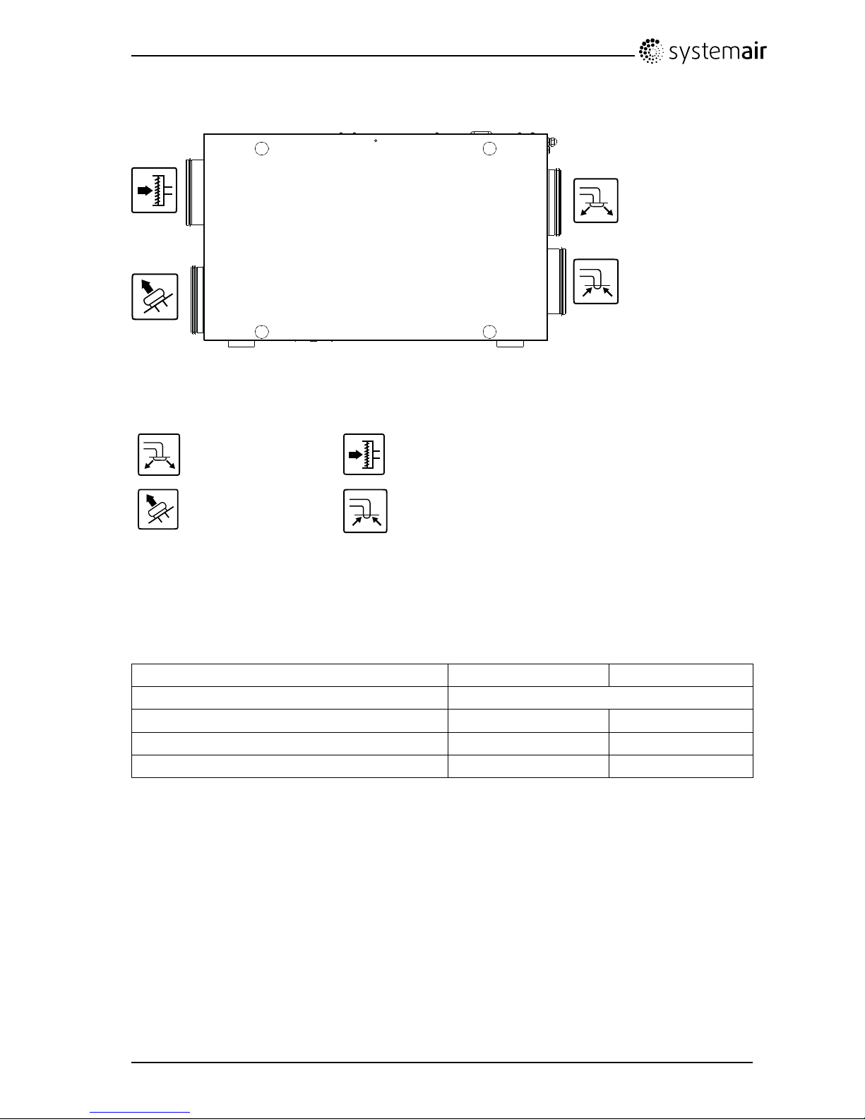
4.3.2Ductconnections
Fig.2Ductconnections
Symbol
Description
Symbol
Description
SupplyairOutdoorair
ExhaustairExtractair
4.3.3Powerconsumptionandfusesize
SAVEVSR300/500comewith1670Winstalledre-heaterbattery.
Model
VSR300VSR500
Re-heater1670W
Fans166W338W
Totalpowerconsumption1836W2008W
Fuse10A13A
5Installation
Thissectiondescribeshowtoinstalltheunitcorrectly.T oensureaproperandfail-freeoperation,itis
importantthattheunitisinstalledaccordingtotheseinstructions.
5.1Unpacking
Verifythatallorderedequipmentaredeliveredbeforestartingtheinstallation.Anydiscrepanciesfromthe
orderedequipmentmustbereportedtothesupplierofSystemairproducts.
SAVEVSR300/500InstallationandService
208115
4
SystemairAB
Page 9
5.2Where/howtoinstall
TheSAVEVSR300/500shouldpreferablybeinstalledinaseparateroom(e.g.storeroom,laundryroom
orsimilar.),butcanalsobeinstalledintheloftspace.
Whenchoosingtheinstallationposition,considerationmustbetakenthattheunitrequiresregular
maintenance.Flooringboardsmustbemounteduptoandundertheunit.Lightandmainssupplyshould
beinstalled.Leavefreespaceforremovingofinspectiondoorsandfortakingoutmaincomponents
insidetheunit.
TheSAVEVSR300/500aresuppliedwithapproximately1mcableandplugfor230V,singlephase
earthedconnection.
Recommendedinstallationlocationfortheoutdoorairintakeisthenorthernoreasternsideofthebuilding
andwithadistancetoopeningsfordischargeofstaleventilationair,kitchenventilator,centralvacuum
system,waistwaterdrainageandotherpollutionsourceslikeexhaustfromtrafcetc.Staledischarge
airshouldideallybeledviaaroofunittotheoutsideandwithagooddistancetoanyoutdoorairintake,
windowsetc.
Note:
Ifthepassagetotheinstallationlocationisnarrow,removethesidecoversandthesidecoversupport
brackets.
5.3Installationprocedure
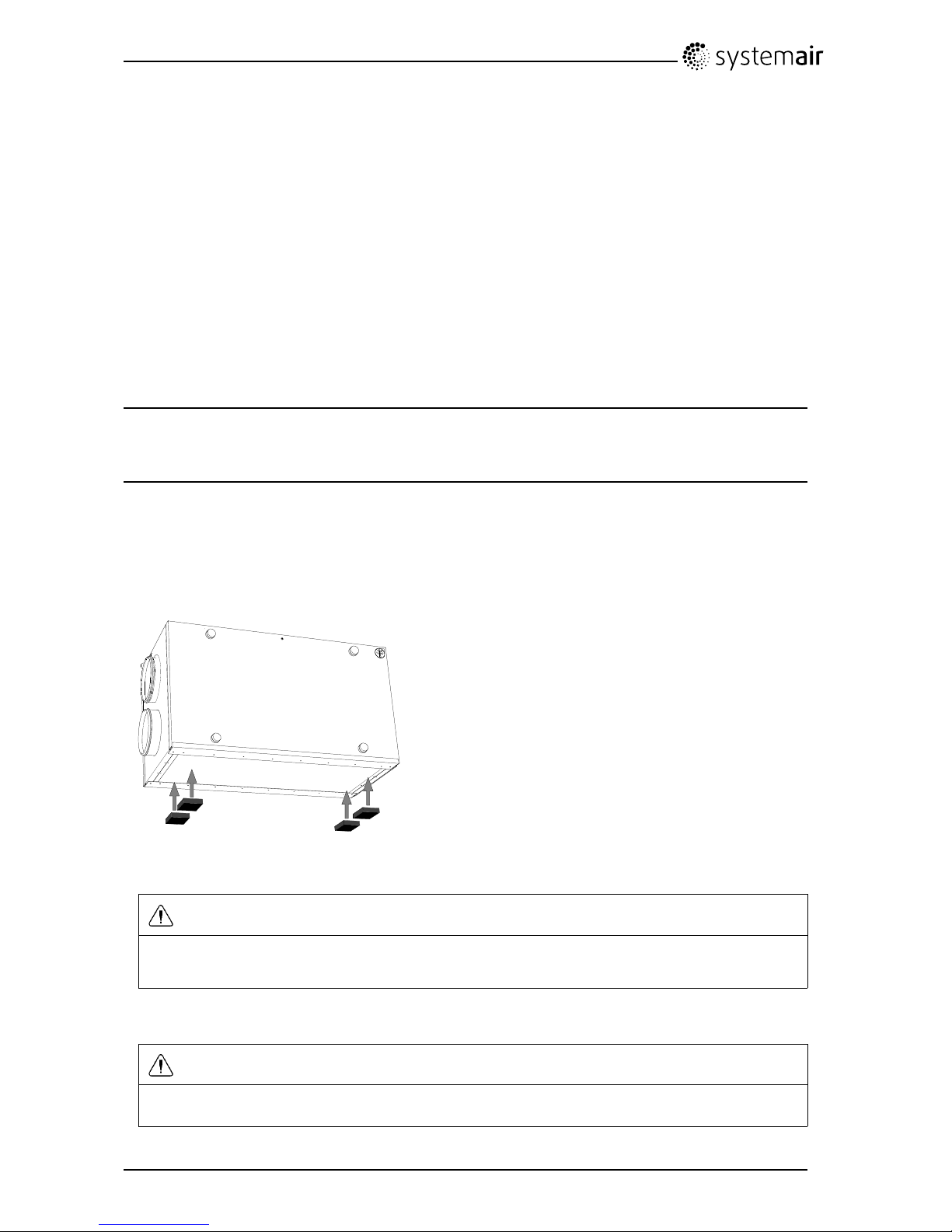
1.Makesurethatthesurfaceisatandhorizontalandthatitsupportstheweightoftheunit.Performthe
installationinaccordancewithlocalrulesandregulations.
2.Fittheenclosedselfadhesivevibrationdampersontheunit.
MountaccordingtotheenclosedVibrationDamperQuickGuide.
3.Lifttheunitinplace
Warning
Bewareofsharpedgesduringmountingandmaintenance.Useprotectivegloves.
Considertheunitweightwhenmounting!
4.Connecttheunittotheductsystem.Makesurethatallnecessaryaccessoriesareusedtocreatea
functionalventilationsolution.
Warning
Theinstallationoftheunitandcompleteventilationsystemmustbeperformedbyanauthorized
installerandinaccordancewithlocalrulesandregulations.
5.Connecttheunitelectricallytothemainswiththeenclosedplugandcheckthatitstartsupcorrectly .
SAVEVSR300/500InstallationandService
208115
5
SystemairAB
Page 10

5.4Condensationdrainage
Ingeneralnocondensationdrainageisneededforrotationalheatexchangersatdryconditions.However,
ifalotofhumidairispresentintheresidence,acondensationdrainagemightbeneeded.Drainage
connectionisavailableasanaccessoryandcanbeorderedseperate.
Note:
Thedrainageconnectionispluggedinthebottomoftheunitatdelivery.T ousethedrainage:elevatethe
unitfromtheoor ,removetherubbersealandandconnectthewaterhose.Connectthewaterhosetothe
sewer.Thewatercannotbeledstraighttothesewerwithoutawatertrap.
5.5Electricalconnections
TheSA VEVSR300/500iswiredinternallyfromfactory.
Theelectricalconnectionboxcanbefoundbeneaththetopcover.Theprintcardcaneasilybetaken
outfromtheunit.
1
1.Printcard
5.5.1Printcardlayout
TheSAVEVSR300/500isequippedwithbuilt-inregulationandinternalwiring.Seebelowillustrationfor
anoverviewoftheenclosedcomponents.
Thegureshowstheprintcard.Seewiringdiagramformoreinformation.
SAVEVSR300/500InstallationandService
208115
6
SystemairAB
Page 11

4
10
8 3
5
7
6
9
1
2
Fig.3Printcard
PositionDescription
1Mainprintcard
2
Printcardforelectricalre-heater
3
Connectiontoexternalcontrolpanel(connectedtounitcasing)
4Mainssupplyconnectionbetweenmainprintcardandelectricalre-heaterprintcard
5
TerminalsforAI1–5(tempsensors)andmotorcontrol
6
Terminalsforexternalconnections
7
Terminalsformainssupplyconnections
8
Terminalsfordigitalinputs(DI1–7)
9
Terminalsforinternalcontrolpanel.
10
Terminalsforregulatedpowersupplytoelectricalre-heater
5.5.2Externalconnectionsontheprintcard
Connectionterminalsforexternalequipmentcanbefoundonthemainprintcardinsidetheunit.
SAVEVSR300/500InstallationandService
208115
7
SystemairAB
Page 12
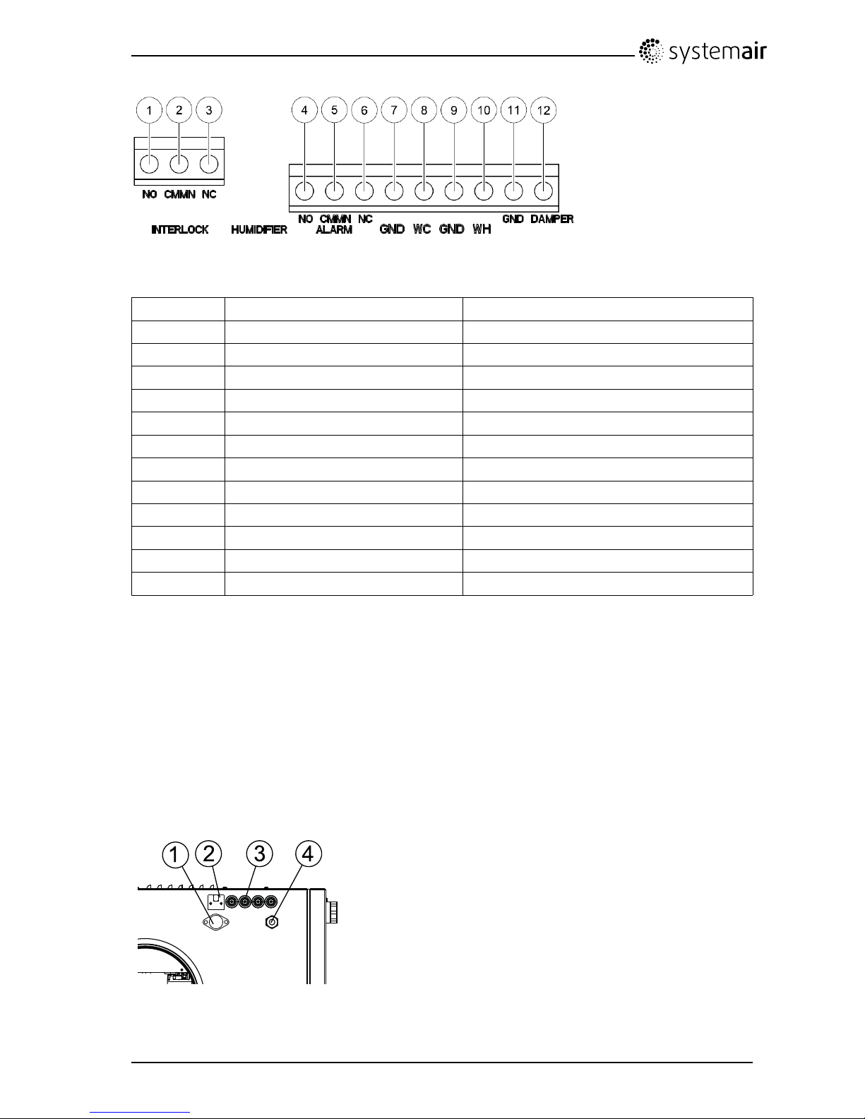
Fig.4Externalconnectionsontheprintcard
PositionDescriptionRemark
1
Outdoor/exhaustairdamper
Normallyopencontact,230V1~,max1A
2
Outdoor/exhaustairdamperReference
3
Outdoor/exhaustairdamper
Normallyclosedcontact,230V1~,max1A
4
Connectiontoexternalalarm
Normallyopencontact,24V ,max1A
5
ConnectiontoexternalalarmReference
6
Connectiontoexternalalarm
Normallyclosedcontact,24V ,max1A
7
GNDReference
8
Watercoolercontrolsignal(AO1)0–10VDC
9
GNDReference
10
Waterheatercontrolsignal(AO2)0–10VDC
11
GNDReference
12
Damper(AO3)
Notused
5.6Externalconnectionsontheunit
Twooftheconnectionsonthemainprintcardarewiredtoplugsontheunitcasing:
•connectiontoanexternalcontrolpanelthroughamodularconnector.
Maximumcablelength:50m.
Cabletype:Flat4–conductorCECPhonecable.
•connectiontoDI3withpossibilitytocongurethefanspeedsindividuallythroughapotentialfree
on/offswitch
1
2 3
4
1.ConnectiontoDI3throughanon/offswitch
2.Connectiontocontrolpanel
3.Cableglands
4.230Vcable
SAVEVSR300/500InstallationandService
208115
8
SystemairAB
Page 13
6Commissioning
6.1Controlpanel
Thecontrolpanelisusedtomakethenecessaryadjustments.
Anexternalcontrolpanelcanbeconnectedtotheunit.Thecontrolpanelisdeliveredwitha12mcable.
Cablesinotherlengthscanbeobtainedfromthesupplier .
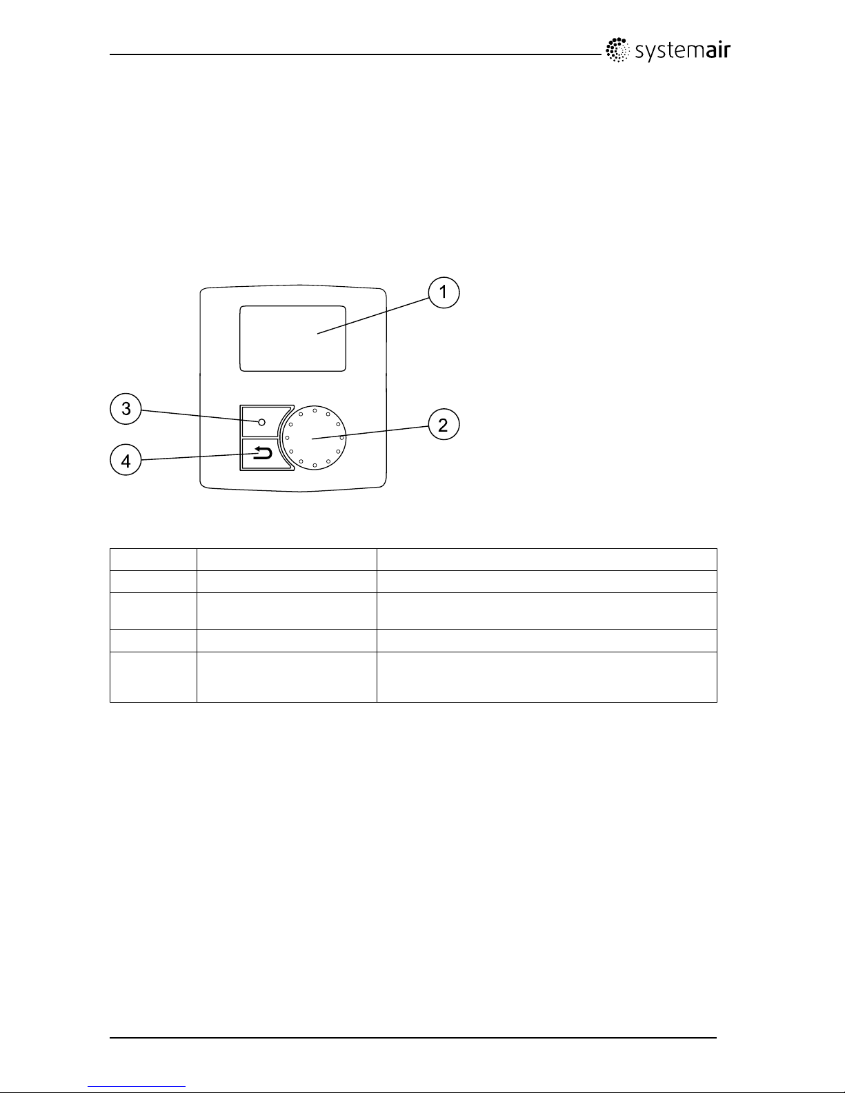
Theillustrationbelowshowsthecontrolpanelwithashortdescription.
1
2
3
4
Fig.5Controlpanel
PositionDescriptionExplanation
1Display
Showssymbols,menusandsettings
2
SELECTIONknob
Movethroughthemenulistsorchangesettingsand
valuesbyturningtheknobleftorright
3
CONFIRMbuttonConrmmenuchoicesorsettingsbypressingthebutton
4
BACKbuttonStepbackinthemenulevelsandtoabortaninitiated
parameterchangeandrestoretheoriginalvalueby
pressingthebutton
SAVEVSR300/500InstallationandService
208115
9
SystemairAB
Page 14

6.1.1Displaysymbols
Symbol
DescriptionExplanation
TempIllustratesthecurrentsettemperature.Thetemperature
setpointissetin6steps(fromcompletelyemptytolled
symbol).
TurntheSELECTIONknobtochoosetemperature.
PressCONFIRMtosavethesetting.
Fanspeed
Illustratesthecurrentfanspeed.Thefanspeedcanbe
setmanuallyin4steps:Off,Low,NomandHigh.
TurntheSELECTIONknobtochoosefanspeed.
PressCONFIRMtosavethesetting.
A.Ventilationoff.
1
B.Lowventilation:Canbeusedwhenleavingthe
buildingforalongerperiod
C.Nominalventilation:Willgiverequiredairchange
undernormalconditions.
D.Maximumventilation:T oincreasetheairowif
necessary.
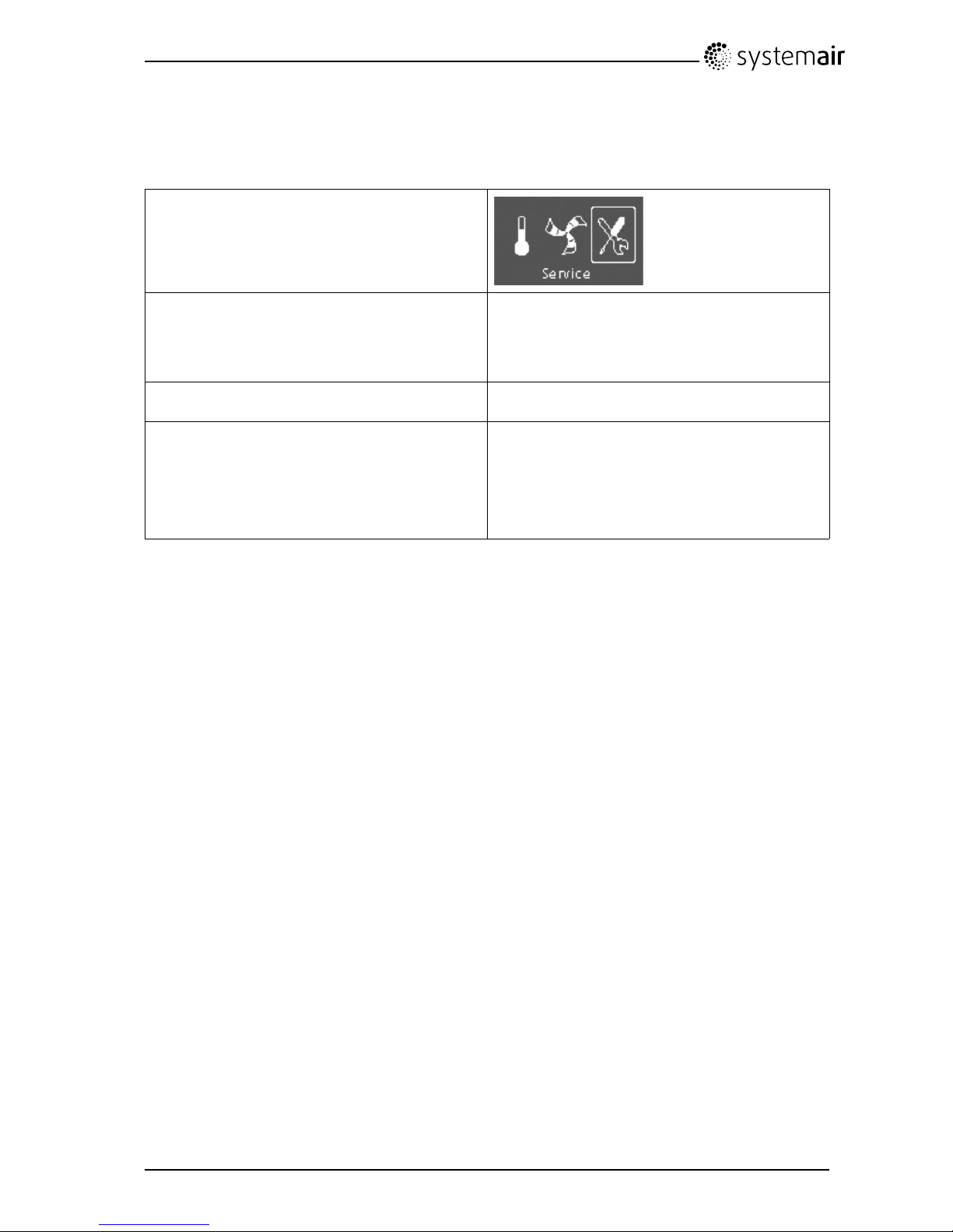
ServicePressCONFIRMtoaccesstheservicemenu.
Alarm
PressCONFIRMtoaccessthealarmlist.
1.ThefancanbesettoOFFbyactivatingMANfanstop.Seeservicemenudescriptionunderfunctions.
Note:
ItisnotrecommendedtoactivateMANfanstop(setfantoOFF)instandardhouseholds.
IfMANfanstopisactivated,theunitshouldbeprovidedwithdampersinexhaustandfreshairductsto
avoidcolddraughtandriskofcondensationwhentheunithasbeenstopped.
SAVEVSR300/500InstallationandService
208115
10
SystemairAB
Page 15

6.2Startupwizard
TheStartupWizardisastep-by-stepcongurationtoolthatstartsautomaticallywhentheSAVEVSR
300/500isstartedforthersttimeorwhen:
•afactoryresetisperformed
•anewprintcardisinstalled(sparepart)
Inthiscasetheunittypemustbeentered(SA VEVSR300/500)
6.2.1Procedure
1.TurntheSELECTIONknobtochooselanguage
andpressCONFIRM
Languages
LanguageENGLISH
2.Chooseunittype,thischoiceisonlypresentifa
newprintcardisinstalled(sparepart)
Type
SAVEVSR300/500
3.Setdateandtime
Time/DateYY/MM/DD
Date:12/09/12
Time:10:00
Weekday:Sat
4.Selectheater:None/Electrical/Water
Heater
Heater:None/Electrical/Water
SAVEVSR300/500InstallationandService
208115
11
SystemairAB
Page 16

5.Setthesystemcurve.
Note:
Beforesettingthesystemcurve,seechapter6.3
fordetails.
Thisfunctionisimplementedintheunitto
compensatetheowvaluesfordifferentsystem
pressures.
SupplyFan(SF):T otalvaluerange:1–20.ForG3
typelter:11–20,forF7typelter:1–10.
VSR300defaultcurve:3
VSR500defaultcurve:3
ExtractFan(EF):V aluerange:1–10
VSR300defaultcurve:3
VSR500defaultcurve:3
Note:
ThefactoryinstalledltersareoflterqualityF7for
thesupplyairandG3fortheextractairlter.
Airltersareaccessoriesandcanbeobtained
fromtheinstallerorwholesaler.
Theltertypeislabelledonthetopofthelter.
Systemcurve
EF:1–10
SF:1–20
6.Hereitispossibletochangethe
Nominal/High/LowairowontheExtract
andSupplyairfans.
Whensettingsaredone,pressCONFIRM.
VSR300:
Airflowl/sEFSF
Nom7070
Max8888
Min4242
VSR500:
Airflowl/sEFSF
Nom105105
Max146146
Min6363
SAVEVSR300/500InstallationandService
208115
12
SystemairAB
Page 17

6.2.2PerformFactoryreset
Howtoperformafactoryresetifnecessary:
1.Entertheservicemenubyselectingtheservice
symbolinthedisplayandpressCONFIRM.
2.Gotopasswordandenterthepassword,
default111 1
UsetheSELECTIONknobforeachdigitand
conrmwiththeCONFIRMbuttonaftereachset
digitandchooseNOforthesystemnotbelocked.
Password
PasswordXXXX
LockedYES/NO
3.GotoFunctionsandselectFactoryReset
Functions
Factoryreset
4.TurntheSELECTIONknobsoYESisshown
andpressCONFIRM.
Factoryreset
Reallyreset?YES/NO
5.ACCEPTEDisshowninthedisplaywindow
ACCEPTED
6.TheStartupWizardstartsafterapproximately
10seconds
SAVEVSR300/500InstallationandService
208115
13
SystemairAB
Page 18

6.3Systemcurves
Asystemrequiresdifferentpressuresatdifferentairows,whichcanberepresentedbyasystemcurve.
Theintersectionbetweenthesystemlineandthefancurve,istheunit'sworkingpoint.Itisshowingthe
airowthesystemisgoingtohave.Everychangeinthepressureoftheventilationsystem,willgive
risetoanewsystemcurve.
TheK-factorisaconstantthatisthesamethroughoutoneandthesamesystemcurve.IftheK-factorand
thesystempressureisknown,theairowcanbecalculated.Iftherealpressuredropinthesystemis
largerorsmallerthancalculated,theworkingpointandtheairowwillbedifferentthanexpected.
6.3.1VSR300Supplyair,F7typelter
0
100
200
300
400
500
600
700
0 20 40 60 80 100 120
Pa
l/s
10V
6,9V
4,9V
2,8V
1
2
3
4
5
6
7
8
9
10
Fig.6Supplyairsystemcurves,F7typelter
SystemcurveK-factor[l/s]
117,12
29,82
36,92
45,33
5
4,18
63,31
7
2,59
82,02
91,54
101,12
SAVEVSR300/500InstallationandService
208115
14
SystemairAB
Page 19

6.3.2VSR300Supplyair,G3typelter
0
100
200
300
400
500
600
700
0 20 40 60 80 100 120
Pa
l/s
10V
6,9V
4,9V
2,8V
11
12
13
14
15
16
17
18
19
20
Fig.7Supplyairsystemcurves,G3typelter
SystemcurveK-factor[l/s]
1118,33
129,58
136,98
145,36
154,24
163,34
172,60
182,04
191,56
201,14
SAVEVSR300/500InstallationandService
208115
15
SystemairAB
Page 20

6.3.3VSR300Extractair,G3typelter
0
100
200
300
400
500
600
700
0 20 40 60 80 100 120
Pa
l/s
10 V
6,9 V
4,9 V
2,8 V
1
2
3
4
5
6
7
8
9
10
Fig.8Extractairsystemcurves,G3typelter
SystemcurveK-factor[l/s]
115,73
29,56
36,94
45,32
5
4,23
63,40
7
2,71
82,10
91,58
101,14
SAVEVSR300/500InstallationandService
208115
16
SystemairAB
Page 21

6.3.4VSR500Supplyair,F7typelter
0
100
200
300
400
500
600
700
0 20 40 60 80 100 120 1 40 160 180 200
Pa
l/s
10 V
6,9 V
5,1 V
2,9 V
1
2
3
4
5
6
7
8
9
10
Fig.9Supplyairsystemcurves,F7typelter
SystemcurveK-factor[l/s]
122,18
213,00
39,45
47,37
5
5,91
64,76
7
3,80
82,97
92,26
101,63
SAVEVSR300/500InstallationandService
208115
17
SystemairAB
Page 22

6.3.5VSR500Supplyair,G3typelter
0
100
200
300
400
500
600
700
0 20 40 60 80 100 120 140 160 180 20 0
Pa
l/s
10V
6,9V
5,1V
2,9V
11
12
13
14
15
16
17
18
19
20
Fig.10Supplyairsystemcurves,G3typelter
SystemcurveK-factor[l/s]
1124,85
1214,21
1310,05
147,64
156,03
164,83
173,85
183,02
192,29
201,64
SAVEVSR300/500InstallationandService
208115
18
SystemairAB
Page 23

6.3.6VSR500Extractair,G3typelter
0
100
200
300
400
500
600
700
0 50 100 150 200 250
Pa
l/s
10 V
6,9 V
5,1 V
2,9 V
1
2
3
4
5
6
7
8
910
Fig.11Extractairsystemcurves,G3typelter
SystemcurveK-factor[l/s]
125,86
215,01
310,74
48,08
5
6,38
65,13
7
4,12
83,22
92,42
101,74
SAVEVSR300/500InstallationandService
208115
19
SystemairAB
Page 24

6.4Fanspeedsettings
Thefanspeedmaybeadjustedinfoursteps;off,low,nominalandhigh.Thesesettingscontroltheoutput
signalstothesupply-andextractfans.Thefactorysettingoneachspeedstepsare:
VSR300VSR500
•Off:0l/s
•Min:42l/s
•Nom:70l/s(atapproximately90Pa)
•Max:88l/s
•Off:0l/s
•Min:63l/s
•Nom:105l/s(atapproximately90Pa)
•Max:146l/s
Theselevelsarepossibletochangeintheservicelevel.
Note:
ThefancanbesettoOFFbyactivatingMANfanstop.Seeservicemenudescriptionunderfunctions.
ItishowevernotrecommendedtoactivateMANfanstop(setfantoOFF)instandardhouseholds.
IfMANfanstopisactivated,theunitshouldbeprovidedwithdampersinexhaustandfreshairductsto
avoidcolddraughtandriskofcondensationwhentheunithasbeenstopped.
Seebelowairowdiagramtogetanideaofhowtheairowcorrespondstoeachvoltageoutput.This
showsafanperformancediagramdisplayingperformancecurvesforsupplyairandextractair.
Fig.12Fanperformancediagram
1.Fanperformancecurve,supplyair
2.Fanperformancecurve,extractair
SAVEVSR300/500InstallationandService
208115
20
SystemairAB
Page 25

6.4.1Settingthefanspeed
1.Gototheservicemenubyusingthe
SELECTIONknob
2.Entertheservicelevelbytypingthepassword,
default1111.UsetheSELECTIONknobforeach
digitandconrmwiththeCONFIRMbuttonafter
eachsetdigitandchoose"NO"forthesystemnot
belocked.
Password
PasswordXXXX
LockedYES/NO
3.Goto:Functions
Choose:Airflow
Functions
—>Airflow
4.Setthefanspeed.All3speedcategoriescanbe
setbetweensystemdenedMinandMaxvalues.
VSR300:
Airflowl/sEFSF
Nom7070
Max8888
Min4242
VSR500:
Airflowl/sEFSF
Nom105105
Max146146
Min6363
SAVEVSR300/500InstallationandService
208115
21
SystemairAB
Page 26

6.5Defrostlevelsettings
Theunitisequippedwithanautomatictwo-stepsdefrostfunctionthatisactivatedwhenthereisriskof
icingintheareaaroundtheheatexchanger .Thesetting0-5(table2)determineshowaggressivethe
defrostingwillbe.Defaultfactorysettingismode0.
Note:
Theheatexchangershouldwithstandlowoutdoortemperatures,butinthosecaseswhereicingcanoccur
pleasebeawareofthatthetwostepdefrostsettingwillgenerateanunderpressureinthebuilding.
Usingareplace,beawarethatthereisapossibleriskofsmokebeingextractedintothelivingareas
duetounderpressureifdefrostingisactivated.
Table1:Defrostlevels
Defrost
mode
Relativehumidityindoors
1
Description
0
Defrostingisturnedoff
1
Minimum<20%Dryareas,suchaswarehousebuildingswithfewpeopleor
industrialbuildingsthatdon’tusewaterintheirproduction
process.
2
Low30%-40%Ofcebuildings
3
Medium40%-60%
Apartmentsorhouseswithnormalhumidity
2
4
High60%-80%
Apartmentsorhouseswithhighhumidity
5
Extremelyhigh>80%
Buildingswithveryhighhumiditylevel.
1.Relativehumidityintheextractairatcoldoutdoortemperatures.
2.Innewlyconstructedhousesitmightbenecessarywithahigherdefrostlevelduringtherstwinterperiod.
6.5.1Settingthedefrostlevel
1.Gototheservicemenubyusingthe
SELECTIONknob.
2.Entertheservicelevelbytypingthepassword,
default1111.UsetheSELECTIONknobforeach
digitandconrmwiththeCONFIRMbuttonafter
eachsetdigitandchoose"NO"forthesystemnot
belocked.
Password
PasswordXXXX
LockedYES/NO
3.Goto:Functions
Choose:Defrosting
Functions
Defrosting
4.Setthemode,0–5
Defrosting
Mode0–5
SAVEVSR300/500InstallationandService
208115
22
SystemairAB
Page 27

6.6ProgrammingtheWeekschedule
Settheweekscheduleaccordingtobelowprocedure:
1.Gototheservicemenubyusingthe
SELECTIONknob.
2.Entertheservicelevelbytypingthepassword,
default1111.UsetheSELECTIONknobforeach
digitandconrmwiththeCONFIRMbuttonafter
eachsetdigitandchoose"NO"forthesystemnot
belocked.
Password
PasswordXXXX
LockedYES/NO
3.Goto:Weekprogram
Service
Weekprogram
4.ChooseWeekprogramagain.
Weekprogram
Fanspeed
4.Setweekdayandtimeyouwanttheunitto
beinONlevel.Twoperiodsperdaycanbe
programmed.Therestofthetimetheunitwillbein
OFFlevel.
Weekprogram
Day:MON
Per1:07:0016:00
Per2:00:0000:00
5.Gobacktothepreviousdialogueframewiththe
BACKbuttonandgodowntoFanspeed.
Weekprogram
Fanspeed
7.Setwhichfanspeedthefanissupposedtobe
runningintheONlevel,choosebetweenLow,
NomorHigh.
Setwhichfanspeedthefanissupposedtobe
runningintheOFFlevel,choosebetweenOFF,
Low,NomorHigh.
Note:
Ifanelectricalre-heaterbatteryisinstalledand
activeandtheunitisshutdownfromthecontrol
panel,forexamplebychoosingOFF .Whenthe
unitisinOFFlevelintheweekprogram,thefans
willcontinuetorunfor3minutes,topreventthe
heaterfromtriggeringtheoverheatprotection
sensor,beforetheystop.
Fanspeed
Onlevel:low/nom/high
Offlevel:off/low/nom/high
8.StepbackwiththeBACKbuttonuntilyoureach
themainmenudisplay
SAVEVSR300/500InstallationandService
208115
23
SystemairAB
Page 28
6.7Ext/Forcerun
Itispossibletoprogramextendedtimeyouwanttheunittoworkunderoperationconditionsotherthan
determinedbytheweekschedule.
1.Gototheservicemenubyusingthe
SELECTIONknob.
2.Entertheservicelevelbytypingthepassword,
default1111.UsetheSELECTIONknobforeach
digitandconrmwiththeCONFIRMbuttonafter
eachsetdigitandchoose"NO"forthesystemnot
belocked.
Password
PasswordXXXX
LockedYES/NO
3.Goto:Ext/ForceRun
Service
Ext/ForceRun
4.Setthetimeinminutestheunitistorunin
extended/forcedrunningmode.Valuerange:
0–240minutes.
Setthefanspeedforthismode.Choosebetween
Low,NomorHigh.
Defaultvalue:Nom.
Ext/ForceRun
Minutes:0
Fanspeed:Nominal
6.8Extrafunctions
Theunitisequippedwithanumberofextraon/offfunctionswhichcanbeactivatedfromexternalon/off
switchesthatcanbeconnectedtothedigitalinputsonthemainprintcard(seewiringdiagram).
Thefollowingpossibilitiesareavailable:
•Digitalinputs1–3:Byconnectingon/offswitchestotheseinputsit’spossibletochoose3individual
fanspeedsettingsinthecontrolpaneldependingonatemporaryneedforthebuilding(forexample
loweringtheextractairfanspeedwhenanopenreplaceisused).Seechapter8.5.
DI3,ispreparedandalreadyconnectedinternallyforeasyaccessononegableendoftheunit.See
chapter5.6.
•Digitalinput4:Makesitpossibletoturntheelectricalre-heaterbatteryonoroff.
Activatedinputmeansthattheelectricalre-heaterisblocked.
•Digitalinput5:ActivatetheExtended/forcedrunningfunctionwitharetractiveswitch.Thefunction
overridescurrentfanspeedsettingsandrunsinforcedmodeaccordingtothesettingsinService->
Ext/Forcerun.ChoosebetweenLow,NomandHighforthisfunction.
Theinputiscalculatedbasedonthesignalsfromanimpulse-switch.Ifastandardswitchisused,the
countdownofthesettimestartswhentheswitchisswitchedoff.
•Digitalinput7:Home/leave,switchingonthisinputdecreasestheset-pointforsupplyair-tempwith
10°C.Thisfunctionisusedwhenthebuildingisuninhabitedforalongerperiod.Thisfunctionis
howevernotworkingiftheunithasbeenconguredtooperatewithahotwaterheater.
ItisrecommendedtoconnecteitherofDI1,DI2orDI3inparallelwithDI7.IfDI7isactivated,setthe
fansspeedtomin.FanspeedsettingsaredonewhenconguringDI1,DI2orDI3.
Seemenuoptionsin“ServicemenuOverview”(chapter8.5).
7Beforestartingthesystem
Whentheinstallationisnished,checkthat:
•Theunitisinstalledinaccordancewiththeinstructions
SAVEVSR300/500InstallationandService
208115
24
SystemairAB
Page 29

•Theunitiscorrectlywired
•Outdoorandexhaustairdampersandsilencersareinstalledandthattheductsystemiscorrectly
connectedtotheunit
•Allductsaresufcientlyinsulatedandinstalledaccordingtolocalrulesandregulations
•Outdoorairintakeispositionedwithsufcientdistancetopollutionsources(kitchenventilatorexhaust,
centralvacuumsystemexhaustorsimilar)
•Allexternalequipmentareconnected
•Theunitiscorrectlyconguredandcommissioned
•Theweekscheduleandfanspeedsettingsarecorrectlyprogrammed.
8Operation
8.1Settingtemperature
Thesupplyairtemperatureissetmanuallyin6stepsinthemainmenudisplaybychoosingthe
temperaturesymbol.
Ifanelectricalorwaterre-heaterisinstalledthetemperaturesetpointsare:
12.0,14.5,17.0,19.5and22.0°C.Defaultvalue:12.0°C.
Ifthere-heaterisdeactivated,thetemperaturestepsare:
15.0,16.0,17.0,18.0or19.0°C.Defaultvalue:15.0°C.
Eachtemperaturestepisillustratedbyincreasingthellingofthetemperaturesymbol.
Anunlledtemperaturesymbolisthe6thsetpointandwillactivatemanualsummermode.Seechapter8.3
8.2Manualsettingoffanspeed
Itispossible,atanytime,tomanuallysetthefanspeedinthemainmenudisplay.Bychoosingthefan
symbolandconrmingitispossibletoincreaseordecreasethefanspeedinthe4steps:Off,Low,
NomandHigh.
Bydoingso,youoverridetheprogrammedweekschedulefortheunituntiltheendofthepresenttime
periodintheweekprogram(chapter6.6).
Note:
ThefancanbesettoOFFbyactivatingMANfanstop.Seeservicemenudescriptionunderfunctions.
8.3Manualandautomaticsummermode
Manualsummermodeoccursifonetemperaturesteplowerthanthe12°Cstepisselected.The
temperaturesymbolonthemainmenuisthencompletelyempty.
SAVEVSR300/500InstallationandService
208115
25
SystemairAB
Page 30

Te mp
Ifthere-heaterisactive,itwillswitchoffduringmanualsummermode.Manualsummermodeaborts
automaticallyaftertwominutesifthesupplyairtemperatureisless,orequalto,5°C.
Ifawaterheaterbatteryisinstalledandactivated,themanualsummermodeisabortediftheoutdoorairor
supplyairtemperatureisless,orequalto,5°C.
Theunitwillautomaticallyalternatebetweenwinteroperationwithheatrecoveryandsummeroperation
withoutheatrecovery.
8.4Coolrecovery
Iftheoutdoorairiswarmerthantheextractairandthesupplyairisabovethesetpoint,coolrecovery
occurs.Thisconditionblockstheheatregulationprocess.
8.5Servicemenuoverview
Entertheservicemenubyselectingtheservicesymbolinthedisplay.
MenuLevel1MenuLevel2MenuLevel3Explanation
Service
Password
Password
PasswordXXXX
LockedYES/NO
Entertheservicelevel
bytyping11 11.Usethe
SELECTIONknobforeach
digitandconrmwiththe
CONFIRMbuttonafter
eachsetdigit.NOwill
unlockthesystemand
allowparameterchanges.
Service
ChangePassword
Changepassword
ActualXXXX
NewXXXX
ConfirmXXXX
Setnewpasswordif
necessary.
Incasethenewpassword
wouldbeforgottenor
misplacedit’sstillpossible
toentertheservicelevel
bywriting8642.This
overridestheearlierset
password.
Service
Filterperiod
Filterperiod
Timeto
replace:
12month
ResetNO/YES
Showsselectedtime
intervalbetweenlter
change.
SetResetofthelter
periodtoYESafter
completedlterchange.
Settimebetweenlter
changes.
Service
Time/Date
Time/Date
YY/MM/DD
Date:12/09/12
Time:10:00
Weekday:Sat
Showscurrentsetdate
andtime.
SetCorrectdateandtime.
SAVEVSR300/500InstallationandService
208115
26
SystemairAB
Page 31

MenuLevel1MenuLevel2MenuLevel3Explanation
Service
Ext/ForceRun
Ext/ForceRun
Minutes:0
Fanspeed:
Nominal
Usethisdialogueframe
toprogramextendedtime
youwanttheunittowork
underoperationconditions
otherthandeterminedby
theweekschedule.
Showssettimefor
extended/forcedrunning.
ShowsSetfanspeed.
Setthetimeinminutes
theunitistorunin
extended/forcedrunning
mode.V aluerange:0–240
minutes.
Setthefanspeedforthis
mode.Choosebetween
Low,NomorHigh.
Defaultvalue:Nom.
Weekprogram
Weekprogram
Weekprogram
Day:MON
Per1:07:0016:00
Per2:00:0000:00
Programhowyouwantthe
unittooperateaccording
totheweekschedule.It’s
possibletoset2periods
perday.
Setweekdayandtime
intervalforthetimeyou
wanttheunittobeinON
mode.
Service
Weekprogram
Weekprogram
Fanspeed
Fanspeed
Onlevel:
low/nom/high
Offlevel:
off/low/nom/high
Usethisdialogueframe
todeterminetheONand
OFFspeedforthefansin
theweekschedule.
SetONlevel.
ChoosebetweenLow,
NomorHigh.
Defaultvalue:Nom
SetOFFlevel.
ChoosebetweenOFF ,
Low,NomorHigh.
Defaultvalue:Low.
SAVEVSR300/500InstallationandService
208115
27
SystemairAB
Page 32

MenuLevel1MenuLevel2MenuLevel3Explanation
Service
Fanspeedlog
Fanspeedlog
Level:1–5
Reset:NO/YES
SF:140/140
EF:140/140
Usethisdialogueframe
toseehowthefanshave
operatedduringthetime
(h)theyhavebeenactive.
Thespeedsareshownin
5differentlevels:
•Level1:0%
•Level2:1–29%
•Level3:30–44%
•Level4:45–59%
•Level5:60–100%
Choosebetweenthelevels
toseethetimeinhours
thefanshavebeenactive
inthedifferentlevels.
ResetYesresetstheSF
andEFtimeintheleft
columnforalllevels.The
rightcolumncontinuesto
countaheadandcannot
bereset.
Note:
Factoryreset(see
Functions–>Factory
reset)willnotaffectthis
function
SAVEVSR300/500InstallationandService
208115
28
SystemairAB
Page 33

MenuLevel1MenuLevel2MenuLevel3Explanation
Functions
Heater/Cooler
Heater/Cooler
Heater:
None/Electrical/Water
Cooler:None/Water
Usethisdialogueframeto
setuptheunitforheating
and/orcooling.
SetHeatertoNone,
ElectricalorWater.
SetCoolertoNoneor
Water.
Functions
Frost
protection
Frostprotection
Alarmlimit:7°C
Showscurrentsetfrost
protectionalarmlimitin°C
fortheinstalledwatercoil.
SetAlarmlimitin°C.
Defaultvalue:7°C.
Functions
Systemcurve
Systemcurve
EF:1–10
SF:1–20
Thisfunctionisto
compensatetheow
valuesfordifferentsystem
pressures.
Seechapter6.3
Service
Functions
Functions
Airflow
VSR300:
Airflowl/sEFSF
Nom7070
Max8888
Min4242
VSR500:
Airflowl/sEFSF
Nom105105
Max146146
Min6363
Usethisdialogueframe
tosetthefanspeedin
l/s.Thespeedcanbeset
individuallyforeachfan
EF:Extractfan,
SF:Supplyfan
SetthefanspeedforEF
andSFforeachstep(Low,
Nom,andHigh.
Functions
Airflowunit
Airflowunit
l/s
m3/h
Defaultvalue:l/s
Functions
Manualfanstop
Manualfanstop
Allowmanualfan
stopY/N
Setifitshouldbepossible
toturnoffthefansinthe
unitmanuallyfromthe
controlpanel.
ChosebetweenYandN.
IfYisselectedthefans
canbeturnedoffbyturning
theSELECTIONknobto
emptyfan
SAVEVSR300/500InstallationandService
208115
29
SystemairAB
Page 34

MenuLevel1MenuLevel2MenuLevel3Explanation
Functions
Analoginput
Analoginput
1:SS20.0
2:ETS23.0
3:Unused
4:OT/FPS20.0
5:OS10.5
Showsanalogueinputs
fromactivetemperature
sensors.
SS:Supplyairtemp
sensor.
ETS:Extractairtemp
sensor.
OT/FPS:Overheat
protectionsensor/Frost
protectionsensor.
OS:Outdoorairtemp
sensor.
Functions
Analogoutput
Analogoutput
A01
auto/man/off0.0V
A02
auto/man/off7.3V
A03
auto/man/off0.0V
Showscurrentanalogue
outputsin0–10Vto
hot/coldwateractuator.
SetAO1(Analogueoutput
tohotwateractuator)to
auto,manoroff.
Defaultvalue:off.
SetAO2(Analogueoutput
tocoldwateractuator)to
auto,manoroff.
Defaultvalue:off.
AO3Notused.
Functions
Digitalinput
Digitalinput
DI1ON/OFF
DI2ON/OFF
DI3ON/OFF
DI4ON/OFF
DI5ON/OFF
DI6ON/OFF
DI7ON/OFF
Showscurrentsettingof
thedigitalinputsONor
OFF
DI1:Fanconguration
DI2:Fanconguration
DI3:Fanconguration
DI4:Heaterstopped
DI5:Extended/forced
running
DI6:Rotorsensor
DI7:Home/leave
SAVEVSR300/500InstallationandService
208115
30
SystemairAB
Page 35

MenuLevel1MenuLevel2MenuLevel3Explanation
Functions
ConfigDI1–3
ConfigDI1–3
1SFhighEFnom
2SFoffEFlow
3SFhighEFhigh
Usethisdialogueframe
tosethowyouwantthe
fanstoreactto3different
digitalinputswhenthey
areswitchedonoroff(the
settingsinthecolumnto
theleftareexamples).
On/offswitchesneedto
beconnectedphysically
toterminalsonthemain
printcardtoobtainthe
differentfunctions.Seethe
wiringdiagramformore
information.
Setthesupplyairfan(SF)
andextractairfan(EF)to
off,low,nomorHighfor
digitalinputs1–3
SAVEVSR300/500InstallationandService
208115
31
SystemairAB
Page 36

MenuLevel1MenuLevel2MenuLevel3Explanation
Functions
DI4–7
DI4–7
4Stopheat
5Extrun
6Rotor
7Home/Leave
DI4–7aredefaultset
fromfactoryandcan’t
bechangedbythe
user.Belowfollowsa
shortdescriptionofeach
function.
DI4:Makesitpossibleto
turntheelectricalre-heater
batteryonoroff.Activated
inputmeansthatthe
electricalre-heateris
blocked.
DI5:Activatethe
Extended/forcedrunning
function.Thefunction
overridescurrentsetfan
speedsettingsandrunsin
forcedmodeaccordingto
thesettingsinService->
Ext/Forcerun.Choose
betweenLow,Nomand
Highforthisfunction..
Theinputiscalculated
basedonthesignalsfrom
animpulse-switch.Ifa
standardswitchisused,
thecountdownoftheset
timestartswhentheswitch
isswitchedoff.
DI6:Rotorsensor.
DI7:Switchingonthis
inputdecreasesthesupply
airtempsetpointwith
10°C.
Thisfunctionisusedwhen
thebuildingisuninhabited
foralongerperiod.
Itisrecommendedto
connectDI7andDI1or
DI3inparallel.IfDI7is
activated,setthefans
speedtomin.Fanspeed
settingsaredonewhen
conguringDI1/DI3.
Note:
The“Home/Leave”
functionisnotworkingif
Waterheaterisactivated.
SAVEVSR300/500InstallationandService
208115
32
SystemairAB
Page 37
MenuLevel1MenuLevel2MenuLevel3Explanation
Functions
Digitaloutput
Digitaloutput
1:SF67%
2:EF67%
3:RotON/OFF
4:ALARMY/N
5:DmpY/N
6:ReheaterY/N
ShowsThecurrent
settingsofdigitaloutputs
1–5(thesettingsinthe
columntotheleftare
examples).
1:SF67%:Currentset
speedofthesupplyairfan
(shownaspercentageof
themaximumspeed).
2:EF67%Currentset
speedoftheextractairfan
(shownaspercentageof
themaximumspeed).
3:Showsiftherotoris
activeornot.
4:AlarmY/N:Indicatesif
thesum.alarmisactiveor
not
5:DmpOFF:
Outdoor/exhaustair
damperisonoroff(230V
signalrelay).
6:ReheaterY/N:Indicates
iftheelectricalre-heateris
activeornot.
Functions
Defrosting
Defrosting
Mode0–5
Usethisdialogueframe
tosethowaggressive
youwantthedefrosting
functiontooperate(see
chapter6.5).
Functions
Modbus
Modbus
Address1
Baud9600/19200
Parity
None/Even/Odd
InformationaboutModbus
communicationand
variablescanbefoundin
theModbususermanual
forresidentialunitsinthe
onlinecatalogueat
www.systemair.com.
Functions
Factoryreset
Factoryreset
Reallyreset?
YES/NO
Usethisdialogueframeto
returntofactorysettings.
SetYESorNO
Note:
Thiswilleraseallyour
personalsettingsthathave
beendonefortheunit.
Service
Language
Languages
Language
ENGLISH
Usethisdialogueframeto
returntoselectyourlocal
language.
SetLanguagebyturning
theSELECTIONknob.
SAVEVSR300/500InstallationandService
208115
33
SystemairAB
Page 38

MenuLevel1MenuLevel2MenuLevel3Explanation
Service
Versions
VersionVR150
CDEC
Appl.1.08.00
1.22.00
Boot1.00.01
1.01.00
Showscurrentsoftware
versions
Note:
Thesoftwareversionsare
justanexampleandmay
differinaspecicunit.
Service
Alarms
Alarms
FanY
EmT/FrostN
DampY
PbFailN
TempN
FilterY
Showsthealarmlistand
whichalarmsthathave
beentriggered(indicated
byY).Seealarmlist
(chapter9.4.1)
9Service
9.1Warnings
Danger
•Makesurethatthemainssupplytotheunitisdisconnectedbeforeperforminganymaintenanceor
electricalwork!
•Allelectricalconnectionsandmaintenanceworkmustbecarriedoutbyanauthorizedinstallerand
inaccordancewithlocalrulesandregulations.
Warning
•Thesystemshouldoperatecontinuously ,andonlybestoppedformaintenance/service
•Althoughthemainssupplytotheunithasbeendisconnectedthereisstillriskforinjuryduetorotating
partsthathavenotcometoacompletestandstill
•Bewareofsharpedgesduringmaintenance.Useprotectivegloves
•Makesurethatltersaremountedintheirplacebeforerunningthesystem
•Thisproductmustonlybeoperatedbyapersonwhichhassuitableknowledgeoreducationwithin
thiseldorcarriedoutwiththesupervisionofasuitablyqualiedperson.
SAVEVSR300/500InstallationandService
208115
34
SystemairAB
Page 39

9.2Internalcomponents
1
1112
65 87
9
14
4
10
2 3
13
Fig.13Internalcomponents
PositionDescription
1
Supplyairfan
2
Overheatprotectionsensor
3
Overheatprotectionresetbutton
4Internalelectricalre-heater
5
Rotorsensor
6Rotatingheatexchanger
7
Outdoorairsensor
8
Supplyairlter
9
Extractairfan
10
Drivebeltforrotatingheatexchanger
11Rotormotor
12Extractairsensor
13
Extractairlter
14
Supplyairsensor
SAVEVSR300/500InstallationandService
208115
35
SystemairAB
Page 40

9.3Componentdescriptions
9.3.1Fans
ThefanshaveexternalrotormotorsofECtypewhichcanbesteplesslycontrolledindividually20–100%.
Themotorbearingsarelifetimelubricatedandmaintenancefree.Itispossibletoremovethefansfor
cleaning,see“UserManual”formoreinformation.
9.3.2Filters
ThefactoryinstalledltersareoflterqualityF7forthesupplyairandG3fortheextractairlter.Thelters
needtobereplacedwhenpolluted.Newsetsoflterscanbeacquiredfromyourinstallerorwholesaler.
FilterqualityG3canbeinstalledforsupplyairltering.
Theltertypeislabelledonthetopofthelter
Note:
IftypeG3ltersareusedinsteadofF7,thesystemcurveforSupplyFan(SF)mustbechanged:
ForG3typelter:11–20,forF7typelter:1–10.
9.3.3Heatexchanger
SAVEVSR300/500isequippedwithahighlyefcient,rotatingheatexchanger.Requiredsupplyair
temperatureisthereforenormallymaintainedwithoutaddingadditionalheat.
Theheatexchangerisremovableforcleaningandmaintenance,see“UserManual”formoreinformation.
9.3.4Printcard
Themainprintcardcontrolsthefunctionsandsettemperaturesoftheunit.
1
1.Printcard
Itispossibletoconnectexternalaccessoriestoterminalsintheprintcard.Seewiringdiagramformore
information.
9.3.5Temperaturesensors
Fourtemperaturesensors(NTC,10kΩat25°C)areincludedintheunitfromfactoryandpositionedinthe
correspondingairchambers.
Thesensorsareconnectedtothemainprintcard.Seewiringdiagramformoreinformation.
SAVEVSR300/500InstallationandService
208115
36
SystemairAB
Page 41

9.3.6ElectricalRe-heaterbattery
There-heaterbatteryispositionedinthesupplyairchamber.
There-heaterisactivatedbyarelayandswitchesonifthesupplyairtemperatureis2°Clowerthantheset
pointandswitchesoffifoneormoreofthefollowingconditionsaremet:
1.Ifthesupplyairtemperatureismorethan2°Cabovethesetpoint
2.Iftheoverheatprotectionisactivatedorthesensorismalfunctioning
3.Iftheemergencythermostatistriggeredorbroken
4.Ifthesupplyairsensorisinerrorstate
5.Ifthesupplyairfanisnotrunning
6.Iftheheaterissettonotactiveinthemenu.
9.3.7Overheatprotectionresetbutton
Ifthesupplyairtemperatureislow,itcanindicatethattheoverheatprotectionistriggered.Theoverheat
protectioncanberesetbypressingtheresetbutton.
Thebuttonisplacedonthetopcover.
1
1.Resetbutton
9.3.8WaterRe-heaterbattery
Awaterre-heaterbattery(optional),whichcanbeacquiredasanaccessory ,canbecontrolledbythe
analogoutputWH(0-10VDC).ThewaterheaterusesAI4forfrostprotection(OT ,“Overheatprotection”,
changestoFPS,Frostprotectioninthemenu).
Thefrostprotectionsensorshouldthenbeastraponsurfacesensorsituatedonthereturnwatertube.
Sensortype:TG-A130
Thesupplyairsensor(SS)atAI1mustbereplacedwithaductsensorwhichcanbeacquiredasan
accessory.Sensortype:TG-K360.Seewiringdiagramformoreinformation.
Onlyelectricalorwaterre-heaterisallowed,i.e.ifawaterre-heaterisselected,theelectricalre-heateris
deactivatedandviceversa.
Note:
Ifawaterre-heaterbatteryisinstalledwestronglyrecommendyoutoalsoinstallanoutdoorairdamper
withaspringreturnactuator.
9.3.9WaterCooler
Awatercooler(optional)canbeacquiredasanaccessoryandbecontrolledbytheunit.Ifawatercooler
isinstalledthesupplyairsensor(SS)atAI1mustbereplacedwithaductsensorwhichcanbeacquired
asanaccessory .Sensortype:TG-K360.Seewiringdiagramformoreinformation.
SAVEVSR300/500InstallationandService
208115
37
SystemairAB
Page 42

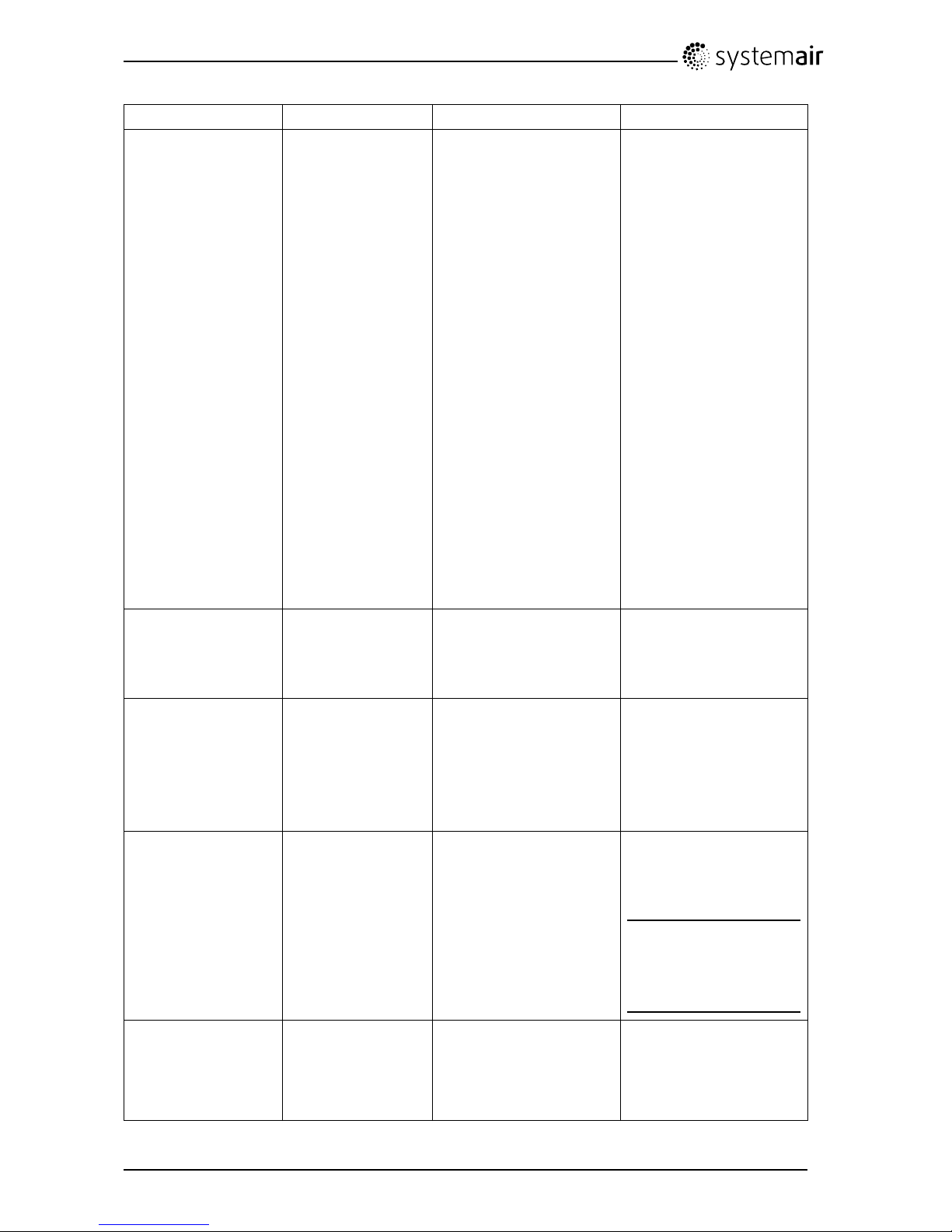
9.4Troubleshooting
Awarningtrianglewithtextinthedisplayindicatesanalarm.Turnmenuselectortothewarningtriangle
andpressconrmtwicetoviewthealarm.
Ifproblemsshouldoccur,pleasechecktheitemsbelowbeforecallingyourservicerepresentative.
Malfunction
Action
Fansdonotstart
1.Checkthedisplayforalarms.
2.Checkthatallfusesandfastcouplingsareconnected(mainssupplyand
fastcouplingsforsupplyandextractairfans).
3.CheckthattheweekprogramisinONmode.Theweekprogrammightbe
inOFFmodewiththefanspeedsettoOFF(chapter6.6)
4.Checkifoneofthedigitalinputs1–3(DI1–3)isactiveandsettooff.This
wouldforceoneorbothfanstostopdependingonthesetup(chapter8.5).
Reducedairow1.Checkthedisplayforalarms.
2.Checksettingoffanspeedinthecontrolpanel(chapter6.1.1).
3.Checkweekprogram(chapter6.6).
4.Checkifoneofthedigitalinputs1–3(DI1–3)isactiveandsettooff.This
wouldforceoneorbothfanstostopdependingonthesetup(chapter8.5).
5.Checklters.Changeofltersrequired?
6.Checkdiffusers/louvres.Cleaningofdiffusers/louvresrequired?
7.Checkfansandheatexchangeblock.Cleaningrequired?
8.Checkifthebuildingsairintakeandroofunit(exhaust)havebeenclogged.
9.Checkvisibleductrunsfordamageand/orbuildupofdust/pollution.
10.Checkdiffuser/louvreopenings.
Theunitcannotbe
controlled
(controlfunctionsare
stuck)
1.Resetcontrolfunctionsbypullingouttheplugfor20-30seconds.
2.Checkthemodularcontactconnectionbetweenthecontrolpaneland
themainprintcard.
SAVEVSR300/500InstallationandService
208115
38
SystemairAB
Page 43

Lowsupplyair
temperature
1.Checkthedisplayforalarms.
2.Checksetsupplyairtemperatureinthecontrolpanel.
3.Checktheanalogueinputsintheservicemenutoverifythatthetemp
sensorsareok(chapter8.5).GotoFunctions>Analogueinput
andverifythetemperaturereadingsfromthetempsensors.
4.Checkiftheoverheatprotectionthermostatisstillalert.Ifnecessary,
resetbypressingtheredbuttonplacedonthetopcoveroftheunit.
5.Checkifdigitalinput4(DI4)issettooff.Thiswouldforcetheelectrical
re-heaterbatterytobeswitchedoff(chapter8.5)
6.Checkiftheextractltermustbechanged.
7.Atverycoldoutdoorconditionsanelectricalorwaterpreheatingbattery
mightbenecessary .Thiscanbeacquiredasanaccessory.
8.Checkthebalancebetweenthesupplyandextractair
Noise/vibrations1.Cleanfanimpellers.
2.Checkthatthescrewsholdingthefansaretightened.
3.Checkthattheantivibrationpadsarettedatthebottomoftheunit.
9.4.1Alarmlist
AlarmExplanation
Dothefollowing
FanIndicateserroroneithersupplyor
extractairfan.
Thealarmisdisplayedinthecontrolpanel.
Contactyourinstallationcompanyorplaceof
purchase.
EMT/FrostIndicatestriggeredfrostprotection
(incaseofinstalledwaterheating
battery)ortriggeredoverheat
protection(incaseofinstalled
electricre-heaterbattery).
Atriggeredfrostprotectionalarmresultsinthe
following:
•Bothfansstop.
•Outdoorandexhaustairdampersclosed.
•Watervalveopenscompletely(10Vsignalgoes
outtotheactuator).
Theunitwillrestartoncethewatertemperature
reaches+5°Cabovethesetfrostprotection
temperature.
Atriggeredoverheatprotectiongivesanalarminthe
controlpanel.
Resetbypushingtheredbuttonplacedonthetop
coveroftheunit..
Iftheproblemcontinuescontactyourinstallation
companyorplaceofpurchase.
Rotor
Indicatesarotormalfunction.
Thealarmisdisplayedinthecontrolpanel.
Therotatingheatexchangerhasstopped.Checkthe
rotorbelt.
Iftheheatexchangerisstillrotating,therotorsensor
maybefaulty.
Contactyourinstallationcompanyorplaceofpurchase
SAVEVSR300/500InstallationandService
208115
39
SystemairAB
Page 44

AlarmExplanation
Dothefollowing
PbFailErrorinconnectionwithrelay
cardfortheelectricalre-heater(if
installedandactivated).
ET2maybetriggeredduetohigh
temperature.
Thealarmisdisplayedinthecontrolpanel.
Theheaterwillnotbeactivated.
FortriggeredET2,wait10–15min.Iftheerror
remains,contactyourinstallationcompanyorplace
ofpurchase.
Temp
Malfunctioninoneormoreofthe
temperaturesensors.
Thealarmisdisplayedinthecontrolpanel.
Contactyourinstallationcompanyorplaceof
purchase.
Filter
Timeforlterchange.
Thealarmisdisplayedinthecontrolpanel.
Changelteraccordingtoinstructionsintheuser
guide.
9.5Replacingrotordrivebelt
IfthealarmRotorisraised,seechapter9.4.1,therotordrivebeltmaybedamagedorbroken.
1
Fig.14Rotordrivebelt
Thereplacementdrivebelt(1)isadjustableanddeliveredwithanippleattachedinoneend.
1.Stoptheunitbydisconnectingthemains.
2.Openandremovethesidecover.
3.Removethebrokendrivebelt.
4.Usetapetoattachthedrivebelttotherotatingheatexchanger,androtatetheexchangerbyhand
togetholdofthedrivebelt.
5.Removethetapeandputthe”empty”endontothenipple.Presstheendsrmlytowardseachother
andtightenthenipple.
6.Pullthedrivebeltontothebeltpulleyandrotatetheexchangerbyhand.Checkthatthebeltpulley
rotates.
Note:
Ifthedrivebeltslips,thedrivebeltmaybetoolongandneedstobeshortened.Cutthedrivebelt5
mmandgotostep5.
7.Replaceandlockthesidecoverandconnecttheunittomains.
8.CheckthatthealarmhasceasedontheControlDisplay.
SAVEVSR300/500InstallationandService
208115
40
SystemairAB
Page 45
Note:
Ifthealarmremains,checktherotorsensor.
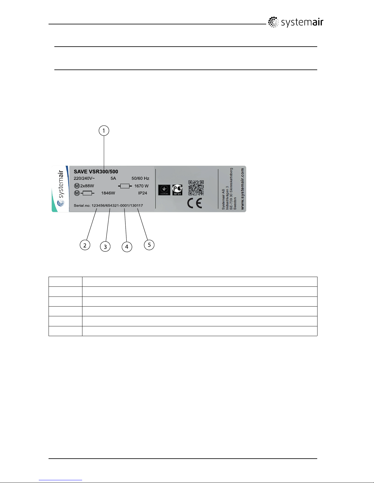
9.6Typelabel
Beforecallingyourservicerepresentative,makeanoteofthespecicationandproductionnumberfrom
thetypelabel,whichcanbefoundonthesideoftheunits,nexttotheexternalconnections.
S AVE VSR 300 /50 0
1670 W
220/240 V~
5A 5 0/6 0 Hz
IP2 418 46W
2x8 8WM
M
Se rial.no: 12345 6/654 321-0 001 /130117
1
2
3
4
5
Fig.15T ypelabel
PositionDescription
1
Productcode(productspecication)
2Productitemnumber
3Productionordernumber
4
Consecutivenumber
5
Productiondate
SAVEVSR300/500InstallationandService
208115
41
SystemairAB
Page 46

lastpage
SystemairABreservestherighttomakechangesandimprovementstothecontents
ofthismanualwithoutpriornotice.
SystemairAB
Industrivägen3
SE-73930Skinnskatteberg,Sweden
Phone+4622244000
Fax+4622244099
www.systemair.com
208115
 Loading...