

SystemAir AW-EX Series, AXC-EX Series, RVK-EX Series, AXCBF-EX Series, DVEX Series Installation And Operating Instructions Manual
Page 1
Stand: / Issue:
Originalanleitung: deutsch
Baureihen:
Axialventilatoren AW-EX; AXC-EX; AXCBF-EX
Dachventilatoren DVEX
Rohrventilatoren RVK-EX
Series:
Axial fans AW-EX; AXC-EX; AXCBF-EX
Roof fans DVEX
Duct fans RVK-EX
Serie:
Axialäktar AW-EX; AXC-EX; AXCBF-EX
Takäktar DVEX
Röräktar RVK-EX
Montage- und Betriebsanleitung
Installation and Operating Instructions
Anvisningar för montering och drift
Руководство по установке и эксплуатации
Instrukcja obsługi i montażu
EX-Ventilatoren / EX Fans
(Ventilatoren für den Einsatz in explosionsgefährdeten Bereichen)
(Fans for use in area in explosion-capable areas)
(äktar för användning i explosiv miljö)
(Вентиляторы для применения во взрывоопасных условиях)
(Wentylatory przeznaczone do pracy w strefach zagrożonych wybuchem)
Seite 3
Page 38
Sida 69
Стр. 100
Strona 134
Серии:
Осевые вентиляторы AW-EX, AXC-EX, AXCBF-EX
Крышные вентиляторы DVEX
Канальные вентиляторы RVK-EX
Typoszeregi:
Wentylatory osiowe AW-EX; AXC-EX; AXCBF-EX
Wentylatory dachowe DVEX
Wentylatory kanałowe RVK-EX
PYC
SE
DE
PL
GB
Page 2

2.4.3 Personnel for operation, use, maintenance and cleaning
Operation, use, maintenance and cleaning may only be done by trained personnel with the authorisation to do so. The
operating personnel must possess knowledge of how to use the fans. In the event of a disturbance or an emergency,
they must be able to react correctly and suitably.
2.4.4 Unauthorised persons
WARNING
Hazard for unauthorised persons!
Unauthorised persons do not know the risks in the work area.
For this reason:
› Keep unauthorised persons away from the work area.
› If in doubt, address the person and eject him/her from the work area.
› Interrupt work as long as unauthorised persons are still in the work area..
2.4.5 Personal protective equipment
WARNING
Health risks!
In order to rule out risks for the employees‘ health, protective clothing must be worn in explosioncapable areas.
› For all work, wear a helmet, safety shoes, ear protection and work protection clothing.
› Pay attention to the information shown in the work area concerning personal protective equipment.
› Wear protective gloves in work to which specic reference is made in these instructions.
2.5 Safety devices
An internal thermistor (PTC) with nished lines for connection to a motor protection device has been installed as an
overheating protection for the motors of the EX fans.
CARE
Property damage from overheating of the motor
» The motor can overheat and be destroyed if the thermo-contacts have not been connected.
» Always connect the thermo-contacts to a motor protection device!
3 Warranty
Warranty for our products shall be based on the contractual stipulations, our quotations and also as a supplement our
General Terms and Conditions of Business. Warranty claims shall presuppose that the products are connected properly,
operated and used in accordance with the data sheets and are also maintained as required.
4 Delivery, transport, storage
4.1 Delivery
Each device leaves our factory in an electrically and mechanically awless condition. The EX fans are supplied on pallets.
We recommend transporting them to the place of assembly in the original packaging.
Warranty 42
Page 3
CARE
Hazard from cutting!
› Wear protective gloves when unpacking.
Check delivery
" Check the Ex fans for obvious defects or other defects which can impair safe operation.
" Above all pay attention to the connection wire, terminal boxes, rotor, cracks in the housing, missing rivets, screws
or covering caps.
4.2 Transport
HAZARD
Loss of explosion protection!
Transport damage can lead to a loss of explosion protection.
› If transport damage can be seen, do not put the device into operation.
› Contact the manufacturer.
WARNING
Risk from hovering loads!
» Do not walk under hovering loads.
» Only move loads under supervision.
» Lower the load when leaving the workplace.
WARNING
Electrical hazard from damaged connection wire or connections
» Do not transport by the connection wire, terminal boxes, rotor or the admission nozzle.
" Transport the EX fan carefully and with suitable lifting equipment.
" Transport the EX fan either in the original packaging or the transport attachments provided for this purpose (e.g.
ring screws; bores in carrying arms, wall ring panels).
" Only lift the EX fan by the transport attachment when unpacking it.
" DVEX: Screw the ring screws in. Transport the fan with them.
" When transporting by hand, pay attention to reasonable human lifting and carrying powers (weight information,
see name plate).
" Avoid blows and impacts and distortion of the housing parts.
4.3 Storage
CARE
Hazard due to loss of function of the motor bearings
» Avoid storing for too long (recommendation: max. 1 year).
» Turn the rotor manually every three months, wear gloves.
» Before installation, check proper function of the motor bearings.
" Store the EX fan in the original packaging dustproof, dry and protected against weather.
" Avoid extreme effects of heat or cold.
Delivery, transport, storage 43
Page 4
5 Description
With a view to the selection of materials, the EX fans full the requirements of Standard DIN EN 14986 (Construction of
fans for use in explosion-capable areas) as a result of specic protective measures in the area of possible contact sur-
faces between rotating and stationary components (rotor/admission nozzle)
5.1 Identication
Example
0820 II 2G c Ex e IIB T3 Gb Sira 07ATEX6341X
CE sign
0820 Notied ofce (quality assurance system)
Device certied for Ex area
II Device group (here: use above ground)
2G Device category and classication (G = gas, D = dust)
c
Ex e
Kind of ignition protection „c“ = constructive safety (not electric)
Kind of ignition protection („d“ = pressure-proof encapsulation, „e“ increased safety, „nA“ =
not sparking)
IIB Groups
T3 Temperature class
Gb EPL (Equipment Protection Level)
Sira 07ATEX6341X EC type test certicate number
Table 1: Identication
Designation
Device group II All areas with explosive atmosphere except mining industrie under-
ground and on the surface at mine gases.
Device category/
classication
„2G“ 2 Category 2 / zone 1 / high safety Devices of this category are inten-
ded for use in areas in which it can be expected that an explosioncapable atmosphere of gases, vapours, mists occasionally occurs.
„3G“ 3 Category 3 / zone 2 / normal safety / Devices of this category are
intended for use in areas in which it cannot be expected that an
explosion-capable atmosphere occurs as a result of gases, vapours,
mists, but if it does occur, then in all probability only rarely and for a
short period of time.
G Gases/vapours/mists
Table 2: Identication
Description 44
Page 5

Designation
Kind of ignition
protection
„c“ Constructive
safety
DIN EN 13463-5
„d“ Pessureproof
encapsulation
Ex d
DIN EN 60079-1
„e“ increased
safety
Ex e
DIN EN 60079-7
Production of sparks, light arcs or inadmissible temperatures which
could act as a source of ignition is prevented by additional measures
and an increased degree of safety.
Non-sparking
equipment
Ex nA
DIN EN 60079-15
Explosion-capable mixtures can penetrate into the housing of the
operating equipment, but may not be ignited. Sparks and ignition-
capable temperatures must be avoided.
Group Group II IIA
IIB
IIC
z. B. Propane ...
z. B. Ethylene ...
z. B. Hydrogen ...
Temperature
class
T1
T2
T3
T4
450 °C
300 °C
200 °C
135 °C
I: Methane
IIA: Acetone, Ammoniac, Methane, Methanol, Propane, Toluene
IIB: Town gas
IIC: Hydrogen
IIA: Ethyl alcohol, n-Butane
IIB: Ethylene
IIC: Acetylene
IIA: Otto fuels, Diesel fuels, fuel oils
IIB: Hydrogen sulphide
IIA: Acetaldehyde, ethyl ether
Table 2: Identication
5.2 Certication according to ATEX directive 2014/34/EU
EC type test certication
Types Certication number Identication Kind of ignition
protection
AW-EX ZELM 05 ATEX0279X II 2G c Ex e IIB T4 c, Ex e
AXCBF-EX Sira 07 ATEX 6341X II 2G c T*
Tu = -20°C ... max. 60°C
(T* is equal to temperature classication of the
motor)
c, Ex e, Ex d, Ex nA
AXC- E X
RVK-EX ZELM 03 ATEX0198X II 2G c Ex e IIB T3 c, Ex e
DVEX SP07ATEX31..X II 2G c Ex e IIB T3 c, Ex e
Table 3: EX identication
Description 45
Page 6
5.3 Technical data
AW-EX AXCBF-EX AXC-EX RVK-EX DVEX
Temperature range [°C]
ambient and material
-20 °C ... +40 °C -20 °C ... max.
60 °C
-20 °C ... max.
60 °C
-20 °C ... +40 °C -20 °C ... +40 °C
Voltage / current strength see name plate
Protection class see name plate
Sound pressure at [dB(A)] 3 m
62 ... 72
3 m
44 ... 82
3 m
47 ... 99
3 m
41
4 m/10 m
44...57/36...49
Dimensions see data sheet
Weight see name plate
Rotor diameter see name plate
Integrated posistor
(PTC
1
))
yes
Table 4: Technical data of the EX fans
1)
Positive temperature coefcient
NOTE
Further technical data can be found in the data sheet of your EX fan.
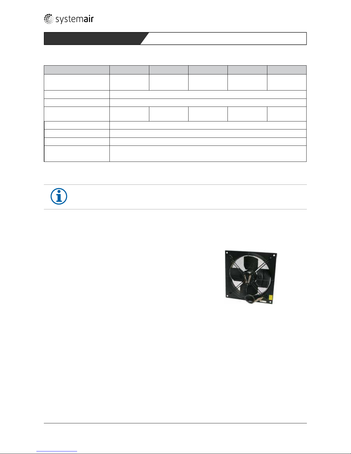
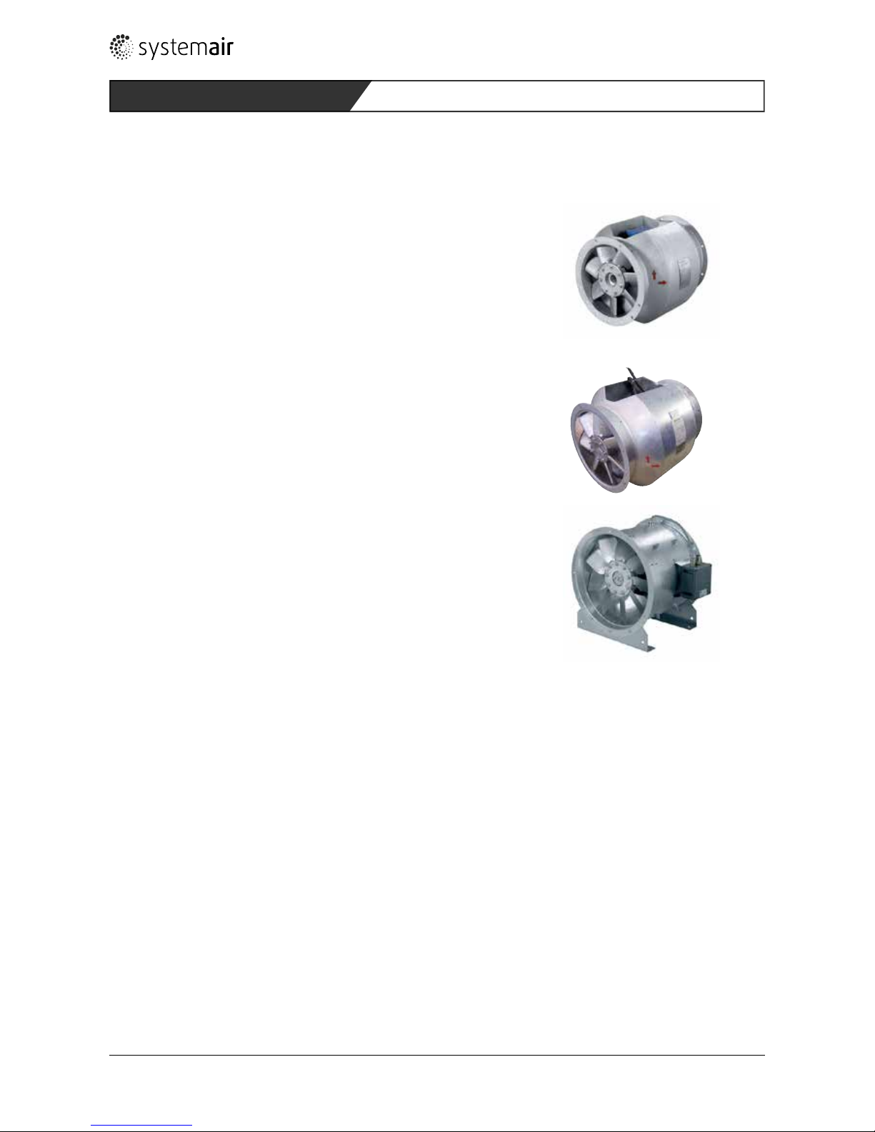
5.4 AW-EX axial fan series
5.4.1 Types
AW 355 D4-2-EX
AW 420 D4-2-EX
AW 550 D6-2-EX
AW 650 D6-2-EX
5.4.2 Description
• Ignition protection class „Ex e“ (increased safety)
• Motor protection by posistor in combination with a suitable motor protection device with EC test type certication
• 2-phased operation thanks to D/Y switching
Fans of the AW-EX series have a voltage-variable external rotor motor with nished wire (65 cm). To make wall tting
possible, they have been attached to a square wall panel.
Housing and axial rotor are made of galvanised and powder-coated sheet steel (RAL9005).
The fans of the AW-EX series can be used for temperature classes T1, T2 and T3 AW-EX355 and 420 also T4). They
convey explosion-capable gases in Zone 1 and Zone 2 as well as groups IIA and IIB.
Description 46
Page 7
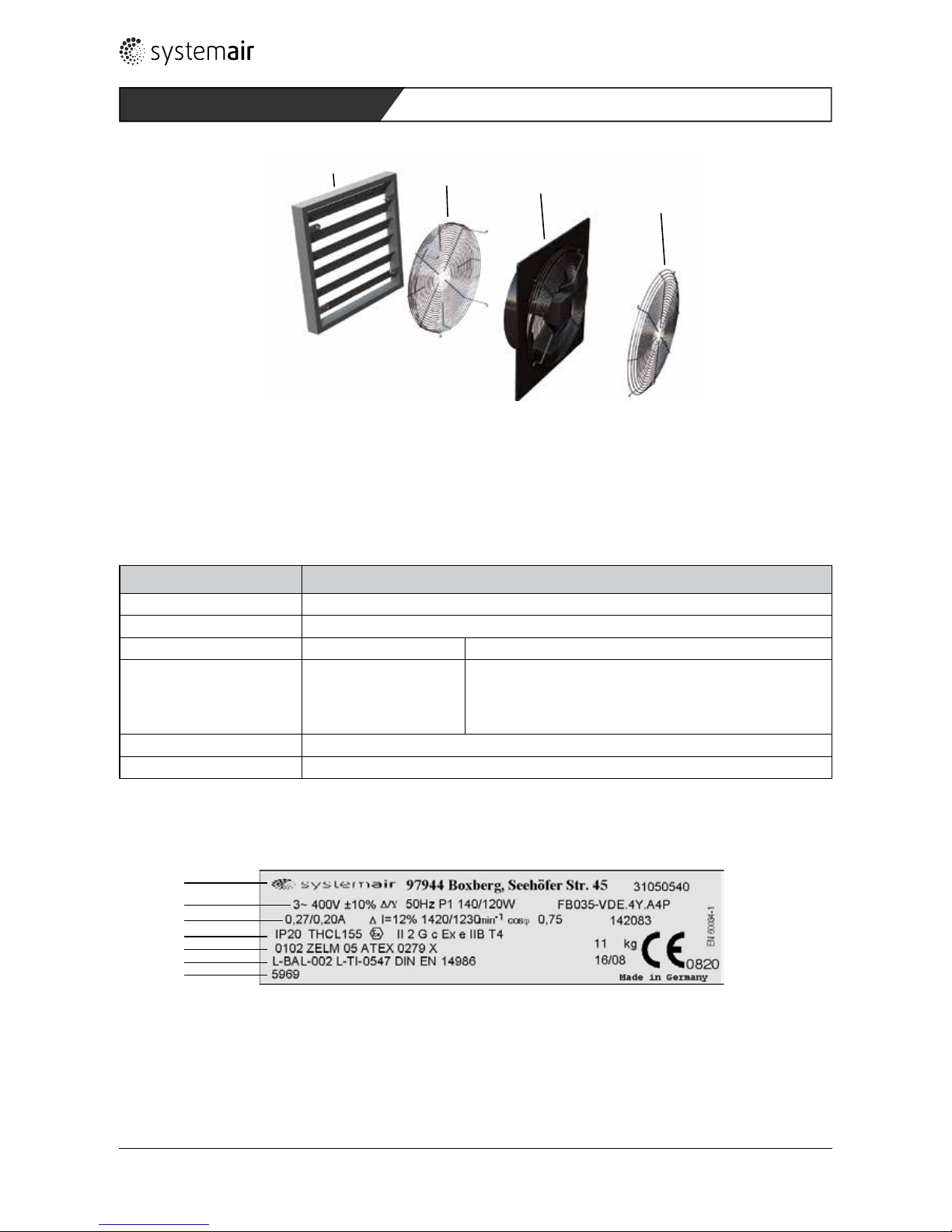
Fig. 1: Fan of the AW-E series with accessories
Legend
1 VK Self-acting covering cap 3 Fan
2 SG-AW Contact-protection grid 4 Contact-protection grid
5.4.3 Type designation
Example AW 355 D4-2-EX
AW Axial fan
355 Size/rotor diameter 355 ... 650
D Kind of motor D: Three-phased current
4 Number of poles 4 V: 4/4-poled variable motor,
S: 6/6- poled variable motor,
4: 4/4-poled
6: 6/6-poled
2 Mechanical version
EX Explosion-protected fan
Table 5: Type key of the AW-EX series
5.4.4 Name plate (example)
1
2
3
4
5
6
7
Fig. 2: Name plate of the AW-EX series
Legend
1 Manufacturer‘s information 5 EC type test certicate number
2 Electrical data 6 Code of the technical documentation (internal)
3 Current / current difference / speed 7 Article no./article designation
4 Protection class / ATEX identication
1
2
3
4
Description 47
Page 8
5.5 AXCBF-EX series / AXC-EX axial fans
5.5.1 Types
AXCBF-EX 250 AXCBF-EX 400
AXCBF-EX 315 AXCBF-EX 500
AXCBF-EX 630 AXCBF-EX 800
AXC-EX 355 ... AXC-EX 1600
5.5.2 Description
• Aerodynamic rotor
• Hub and blades of aluminium die cast
• Housing hot-galvanised steel to DIN EN ISO 1461
• Aluminium slip ring
• Seamed anges to Eurovent standard ½ for high rigidity
• Three-phase motors, IP55, insulation class F, according to EN 60034, IEC 85.
• Admissible ambient temperatures from -20°C to max. 60°C, see Table 6.
• AXC-EX: supplied with Ex e connection box on the outside of the housing
• AXCBF-EX: motor outside the air ow
The divided medium-pressure axial fans of the AXCBF-EX / AXC-EX series are available with rotor diameters from 250
to 1600 mm.
They can be used for temperature classes T1, T2, T3 and T4. They convey explosion-capable gases in Zone 1 and Zone
2 as well as groups IIA, IIB and IIC.
Ex d: The motor has motor protection through an integrated posistor (PTC) and is speed-variable through a frequency
converter.
For temperatures above +40 °C, the maximum motor load according to the following table is to be considered:
Description48
Page 9
Temperature Max. input power in proportion to nominal power in %
40 °C 100 %
45 °C 95 %
50 °C 90 %
55 °C 85 %
60 °C 80 %
Table 6: Motor load
1
2
3
4 5
10
6
7
9
10
Fig. 3: Fans of the AXCBF-EX / AXC-EX series with accessories
Legende
1 SG Protection guard 6 MP (4x angle 90°) Mounting brackets up to size 1000
2 ESD-F Inlet cone 7 LRK Air operated damper
3 RSA Silencer 8 GFL Counterange
4 EV-AR/AXC Flexible connection 9 MFA Mounting feet
5 MPR Mounting ring 10 FSD (4x) AV Spring mounts
Description
8
49
Page 10

5.5.3 Type designation
Examples AXCBF-EX 250-6/28°-2
AXC-EX 355-7/32°-4
AXCBF AXC Axial fan
EX EX Explosion-protected fan
250 355 Size/rotor diameter 250 ... 1.600
6 7 Number of blades
28° 32° Blade angle
2 4 Number of poles
Table 7: Type key of the AXCBF-EX / AXC-EX series
5.5.4 Name plate (example)
Systemair GmbH, 97944 Boxberg-Windischbuch Deutschland
Tel: +49 (0) 7930-92720 Fax: +49(0) 7930-927293
www.systemair.de
RefNr
TypNr
P2 kW
P2 kW
Höchst kW
Höchst kW
Ampere
Ampere
26°
2011
50
400
3
2890
Winkel
Baujahr
Hz
Volt
Phase
U/min
U/min
AXC-EX-500-9/26°-2
5,50
5,10
12
0820 II 2G c
Ex d(e) IIC T4
Sira 07AT EX6341X
ta = -20°- +60°C
Pa. Nummer einfügen
9
7
8
1
2
3
4
5
6
10
11
1 Manufacturer‘s information
2 Product order number
3 Type no. / blade angle
4 Motor output / year of manufacture
5 - / frequency
6 Max. output / voltage
7 - / phases
8 Current / revs./minute
9 Identication to ATEX
10 EC test type certication number
11 Ambient temperature
Fig. 4: Name plate of the AXCBF-EX / AXC-EX series
Description 50
Page 11

5.6 RVK-EX series duct fans
5.6 .1 Type
RVK-EX 315D4
5.6.2 Description
• Ignition protection class „Ex e“ (increased safety)
• Motor protection by posistor (PTC), in combination with a suitable motor protection device with EC test type certica-
tion
• Voltage-variable external rotor with nished wire
Fans of the RVK-EX series have been designed for assembly in ducts. The housing comprises conductive plastic, the
radial rotor has backward-bent blades.
The speed of the RVK-EX 315D4 can be varied via a 5-phase voltage regulator.
The fans can be used for temperature classes T1, T2 and T3. They convey explosion-capable gases in Zone 1 and Zone 2
as well as groups IIA and IIB.
The motor of the fans of the RVK-EX series must be connected to a separate motor-protection device.
They may be operated in the part voltage area. Use of electronic or transforming control appliances, with the exception
of frequency inverters, is admissible. Use of control devices from Systemair GmbH is recommended. Control devices
from other manufacturers must have the same or better quality!
Das Vervielfältigen dieser Zeichnung und Mitteilen
an dritte ist Verboten. Für diese Zeichnung behalten
wir uns alle Rechte gemäß Urheberschutz vor.
This document must not be copied without our written per-
mission, and the contents thereof must not be imparted to
a third party nor be used for any unauthorized purpose.
Contravention will be prosecuted. SYSTEMAIR GmbH
1 3 4 62 5 7 8
Fig. 5: Fan of the RVK-EX series with accessories
Legend
1 IGC Intake lter 5 SG Duct protection grid
2 FFR Filter box 6 FK Connecting sleeve
3 FK Connecting sleeve 7 LDC Sound absorber
4 RVK-EX Duct fan 8 VK Covering cap
Description 51
Page 12

5.6.3 Type designation
Example RVK-EX 315D4 (ATEX)
RVK Duct fan
315 Size / rotor diameter
D Variable
4 Number of poles 4: 4-4poled
2 Mechanical version
ATEX ATEX registration
Table 8: Type key of the RVK-EX series
5.6.4 Name plate (example)
1 Manufacturer‘s information
2 Type designation
3 Voltage / frequency current / date
4 Current / motor insulation class
5 Output / protection class
6 Speed / weight
7 Capacitor output / serial number
8 EC type test certication number
9 Identication to ATEX
Fig 6: Name plate of the RVK-EX series
Description
1
2
3
4
5
6
7
8
9
52
Page 13

5.7 DVEX roof fans series
5.7.1 Types
DVEX 315D4 DVEX 500D6
DVEX 355D4 DVEX 560D6
DVEX 400D4 DVEX 630D6
DVEX 450D4
5.7. 2 Description
• Integrated thermo-contacts (PTC)
• Ignition protection class “Ex e” (increased safety)
• Motor protection by posistor in combination with a suitable motor protection device with EC test type certication
• Voltage-variable external rotor with nished wire
• Installation of sound absorbers possible.
The radial rotor of the vertical blow-out DVEX roof fans has backward-bent rotor blades. Its housing comprises saltwater-proof aluminium. The base frame and an integrated bird-protection grid are on powder-coated, galvanised sheet
steel, the admission nozzle of copper.
The fans can be used for temperature classes T1, T2 and T3. They convey explosion-capable gases in Zone 1 and Zone 2
as well as groups IIA and IIB.
1
2
3
4
5
6
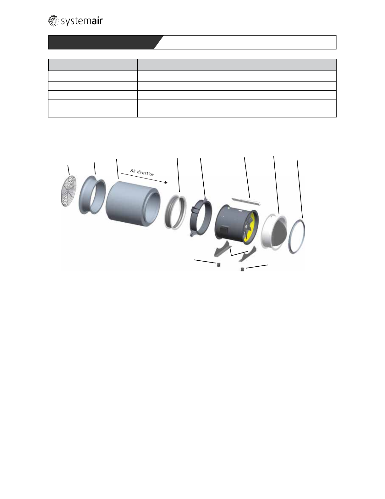
Fig. 7: Fans of the DVEX series with accessories
Legend
1 FTG Hinged frame 4 ASS-EX Flexible connection
2 TDA Adapter frame 5 ASF Intake connection
3 VKS-EX Self-acting covering cap 6 FDS Flat roof base
Description 53
Page 14

5.7. 3 Type designation
Example DVEX 315D4 400V
DVEX Roof fan, explosion-protected
315 Size / rotor diameter 315 ... 630
D Motor class D: three-phased current
4 Number of poles V: 4/4-poled variable motor,
S: 6/6- poled variable motor,
4: 4/4-poled
6: 6/6-poled
400V 400V
Table 9: Type key of the DVEX series
5.7.4 Name plate (example)
1 Manufacturer‘s information
2 Type designation
3 Output / voltage / frequency / current / speed
4 Trigger time / starting/nominal current / insula-
tion class, motor
5 Speed variation
6 Type test certication for U-EK230E motor pro-
tection device
7 Identication to ATEX
8 EC type test certication number
Fig. 8: Name plate of the DVEX series
Description
0,39kW 230 / 400V D/Y 1350 r/m
Systemair GmbH
3 ~ 50Hz
Speedcontrollable 15 to 100% by reduc ing the voltage
1,31 / 0,76A
Insulationclass F
PA-N r:
Seehöfer Strasse 45
97944 Boxberg
GERMANY
'A/ 'N = 3,4
Fan type: DVEX 400D4
t
A=81s
For thermal overload protection us e type
II 2G c
U-EK230E (PTB03ATEX3045)
0820
Ex e IIB T3
SP07ATEX3131X
1
2
3
4
5
6
7
8
54
Page 15

6 Assembly
NOTE
The safety information in Section 6 applies to all the fans described in these operating instructions.
6.1 Safety information
Keep to the following order in order to rule out the risk of injuries from rotating parts:
Assemble
Connect to energy
HAZARD
Hazard of explosion of an ignition-capable atmosphere!
On the intake side, a protective grid has been attached in order to rule out the risk from foreign bodies.
It guarantees a protection class of IP20.
On the pressure side, protection class IP 20 must be guaranteed by assembly of the fan in a duct/
channel system or by tting a protective grid.
• Seal the system carefully.
• Install accessory parts correctly.
Upstream or downstream components or those located directly in the air ow may not manifest any
unprotected aluminium or steel surfaces. Varnishing or a plastic coating fullling at least grid section
characteristic 2 according to DIN EN ISO 2409 is necessary, in order to prevent an alumino-thermal
reaction.
• Assembly may only be done by trained qualied personnel paying attention to the relevant directives.
• Comply with the system-related conditions and the requirements of the system manufacturer or plant builder.
• Only install the fan when and if
– the fan has not been damaged,
– the fan wheel runs freely when turned by hand.
• The fan housing may not be deformed during assembly.
• Safety components, e.g. protective grids, may not be dismantled or circumvented or put out of function.
• Install the fan with protection against dust, moisture and the inuences of the weather.
• Do not distort the fan housing in installation. Surfaces must be at.
• Pay attention to the direction of ow (arrows).
• For maintenance and repair, ensure secure access to the fan.
• Provide for contact, intake protection and safety distances according to DIN EN 294 and DIN 24167-1.
• Ensure uninhibited and even admission into the device and free blow-out.
• In EX fans, the blade angle may not be amended subsequently.
• In installation, guarantee that no vibrations are transferred to the duct/channel system or the housing frame of the
fan in operation. For this purpose, use connecting sleeves and anges from the accessories.
6.2 Axial fans AW-EX, AXC-EX and AXCBF-EX
6. 2.1 Preconditions
AW-EX Only install the fan if the distance between the fan wheel and the housing is constant.
AXC-EX and
AXCBF-EX
Only install the fan if the minimum air gap between the blade tip and the housing matches the
value of your fan in Table 11.
Assembly55
Page 16

6.2.2 Assembly
WARNING
Danger from falling parts!
› Check the underground (ceiling/wall) for strength before assembly,
› when selecting the tting material, pay attention to the weight, vibration tendency and shearing
forces (weight, see name plate).
" Fit the fan on a rm base with suitable tting material at all the tting points.
" Secure the screw connections with Loctite.
" Fit the air channels and the accessories.
" Mounting AXC-EX and AXCBF-EX in horizontal and vertical ( impeller up) position possible!
6.2.3 AW-EX series: minimum air gap
Size Minimum air gap in mm Size Minimum air gap in mm
355 3,50 550 5,50
420 4,20 650 6,45
Table 10: Minimum air gap of various construction sizes
NOTE on the condensation opening of the AW-EX series
Pay attention in installation:
- In installation in a vertical motor shaft position, condensation cannot escape.
- Installation and operation only admissible in a horizontal shaft position
NOTE for an optimised characteristic
To ensure achievement of the characteristic, it is necessary for a constant and twist-free ow to exist at
the inlet. In free intake, this is achieved by the addition of an admission nozzle or a channel line with a
length of no less than 2.5 x D. If this is not possible for construction reasons, a deection piece with
bafes tted in front of the fan must be optimised in its uidics in such a way that a constant speed
distribution at the fan inlet is achieved.
On the pressure side, a channel or duct element with a length of no less than 2.5 x D is also to be
provided for achievement of the characteristic.
6.2.4 AXC-EX und AXCBF-EX series: minimum air gap
Size Minimum air gap in mm Size Minimum air gap in mm
250 2,5 710 5,0
315 2,5 800 5,0
355/400 3,0 900/1000 7,0
450/500 3,5 1250 8,0
560 3,5 1400/1600 10,0
630 4,5
Table 11: Minimum air gap of various construction sizes
Assembly56
Page 17

6.3 RVK-EX duct fans
6. 3.1 Preconditions
• The RTRD control devices and UEK motor protection devices supplied by RTRD must be tted outside the explosion-
capable area.
• When complying with the material combinations, the following minimum gaps must also be complied with:
– between rotating and stationary parts, the minimum gap may not be smaller than 1 % of the decisive contact
diameter, but no less than 2 mm in an axial or radial direction and may not be more than 20 mm.
• Fans without wire grid or without admission nozzle:
– To t on the stationary motor ange, uses screws of strength class 8.8 and secure with Loctite.
– Admissible tightening torques: M6 = 9.5 Nm; M8 = 23 Nm.
• To avoid disturbances and to protect the motor, the latter must be disconnected from the mains by the installed
posistors (DIN 44082-M130) in the event of a disturbance of operation (e.g. inadmissibly high medium temperature)
in combination with a triggering device (identication II (2) G cf. Directive 2014/34/EU).
– Current-dependent protection is not admissible and also not possible as secondary protection.
6.3.2 Assembly
" Use the enclosed holding clamps.
" Screw the holding clamps tight by hand.
NOTE
If the cable gland is loosened this has to be locked properly again (Admissible tightening torques max.
3,8 Nm!).
WARNING
Danger from falling parts!
› Check the underground (ceiling/wall) for strength before assembly,
› when selecting the tting material, pay attention to the weight, vibration tendency and shearing
forces (weight, see name plate).
" Fit the fan on a rm base with suitable tting material.
" Fit the air connection lines and the accessories.
" Make sure that no movable parts are accessible any more after installation (EN 294).
NOTE on the condensation opening of the RVK-EX series
Pay attention in installation:
With a vertical motor axis, the condensation opening at the bottom must be open.
6.4 DVEX roof fans
6.4 .1 Preconditions
• Only install the fan if the minimum air gap between the rotor and the nozzle is 4 ... 8 mm.
• Installation position optional if not stated to the contrary.
• Protective accessories must have been examined with a view to strength and material.
6.4.2 Assembly
Assembly 57
Page 18

WARNING
Danger from falling parts!
› Check the underground (ceiling/wall) for strength before assembly,
› when selecting the tting material, pay attention to the weight, vibration tendency and shearing
forces (weight, see name plate).
" Fit the fan on a rm base with suitable tting material
" Prepare the fan with hinged frame for connection and secure (see Fig. 9 A, B, C)
– Close the fan carefully, do not drop it.
– Secure it with an M 6x10 screw (2 screws from size 450 upwards).
– Secure the two aps by means of an M 8x16 screw. They also act as protection against shutting.
" Fit the air connection lines and the accessories.
NOTE
The channel installation must be such that protection class IP 20 (contact distance rotating part < 12
mm) is fullled on the admission side and protection class IP 10 (contact distance rotating part < 50
mm) can be guaranteed on the blow-out side.
6.4. 2.1 Securing the hinged frame
" If a hinged frame is used, secure the DVEX fan as shown in Fig. 9.
•
M8x16
M8x16
M6x10
A B C
Fig. 9: Secure DVEX fan
7 Electrical connection
NOTE
› The safety information in Section 7.1 applies to all the fans described in these operating instructions.
› The fans may only be installed if the explosion-protected area has been classied according to DIN EN
60079-10 and the Operational Safety Ordinance.
Electrical connection58
Page 19

7.1 Safety notes
HAZARD
Hazard of explosion of an ignition-capable gas/air atmosphere!
If the wire ends which have not been connected are tted to the external current circuits within the
explosion-capable area, a connection box selected to match this area with its own certication and
explosion-protection identication must be used.
The electrical data, information on temperature monitoring and on admissible operation with part
voltage, if applicable, can be seen from the data sheet in question.
The control devices and motor protection devices must be installed outside the explosion-capable area!
Operation on frequency inverters is only admissible for devices with the „Pressure-proof encapsulation
Ex d“ ignition protection class.
WARNING
Risk from electrical voltage!
› Electrical connection only by a trained electrician or trained and instructed qualied personnel!
› Electrical connection in harmony with the valid directives.
› Avoid penetration of water into the terminal box.
› Pay attention to the 5 rules of electrical engineering:
– clear (all-pole separation of an electrical system from live parts),
– secure against switching on again
– establish freedom from voltage,
– earth and short-circuit,
– cover or fence off neighbouring live parts.
" Do not use gland bolt connections of metal if the terminal boxes are of plastic.
" Always connect the thermo-contacts to a motor protection device!
– The motors contain triple posistors. More than two posistor chains may not be switched in series. Maximum test
voltage of the posistors 2.5 V.
– The motor can overheat and be destroyed if the thermo-contacts have not been connected.
" Ground all conductive added and accessory parts.
7.2 AW-EX, AXC-EX and AXCBF-EX axial fans
" Connect the lines according to the connection diagram in the lid of the connection box. The electrical data can be
seen from the name plate or the enclosed data sheet.
Ex motors additionally have a marked external posistor connection.
" Earth the fan on the earth conductor connection.
" AW-EX: If the operational leakage current of 3.5 mA is exceeded, the conditions with a view to grounding pursuant
to DIN VDE 0160/5.88 Art.6.5.2.1 are to be fullled.
" Connect the thermo-contacts/posistor connections to a motor protection device.
For the AW-EX series, please remember
" Seal the screw connections on lids of plastic terminal boxes with sealing putty.
" Depending on the kind of cable insert, provide water discharge bends or use sealing putty.
" Fit the fan connection wire with cable binders on the contact protection grid or the motor struts.
Electrical connection59
Page 20

7.3 RVK-EX duct fans
" Connect the lines according to the connection diagram on the stator or fan housing. The electrical data can be seen
from the name plate or the enclosed data sheet.
Ex motors additionally have a marked external earth conductor connection.
" Earth the fan on the earth conductor connection.
" Connect the thermo-contacts/posistor (DIN 44082-M130) connections to a motor protection device.
" In cases of higher strain (e.g. moist rooms), provide for a cable insert with water discharge bends.
" Additionally seal the compression gland screw connection.
" Fit the motor connection wire with cable binders or cable clamps.
7.4 DVEX roof fans
The wire ends of the fan must be installed such that they are mechanically protected and are suited for use outdoors.
In the event of external connection of the earthing wire, connect it securely to the house earthing device between two
metal panels.
Installation must be done according to Directive EN 60079-14 in harmony with the high voltage directives.
" Connect the lines according to the connection diagram in the lid of the terminal box. The electrical data can be seen
from the name plate or the enclosed data sheet.
Ex motors additionally have a marked external earth conductor connection.
" Earth the fan on the earth conductor connection.
" If there is an increased risk of static charge, a separate earthing should be connected to the housing.
" Connect the thermo-contacts/posistor connections to a motor protection device.
7.5 Cut-out time of the motor protection device
• Determine the cut-out time of the motor protection device. It is the ratio of start current and nominal current (IA/IN).
The ratio must be between 2.9 and 8 at an ambient temperature of 20°C.
• In selection, the admissible chosen current limitation may not deviate by more than 20%.
• The motor protection switches must be designed such that the start current does not trigger the protection switches.
• Connect a motor protection switch (e.g. U-EK230E). It has been tted with a light-emitting diode which lights up
when the motor protection is triggered.
NOTE
The motor protection device must be installed such that it protects the motor against overheating and
cuts out within 15 sec. if the rotor blocks.
7.6 Secure 3-phased motors
Avoiding two-phased runs:
For 3-phased motors, use an effective motor protection, we recommend an all-pole C automatic cut-out.
7.7 Connect temperature monitor
If a temperature monitor is used, it must be connected to a motor protection device.
Electrical connection60
Page 21

8 Commissioning
NOTE
The safety information in Section 8.1 applies to all the fans described in these operating instructions.
8.1 Preconditions
HAZARD
Hazard of explosion of an ignition-capable gas/air atmosphere!
When commissioning the EX fan, the fundamental information from BGR 104 (explosion protection rules
of the employers‘ insurance schemes) and BGR 132 (avoidance of risk of ignition as a result of electrostatic charges) must be known.
• Fitting and electrical installation have been completed properly.
• Residues from assembly and foreign bodies have been removed from the fan area.
• The intake and blow-out openings are free.
• The fan wheel runs freely.
• The safety devices have been tted (contact protection).
• The protective conductors and external earth conductor have been connected.
• The thermo-contacts (temperature monitors) have been properly connected to the motor protection switch.
• The motor protection switch is functioning.
• The temperature monitor is functioning.
• The wire inlet is tight.
• The connection data match the data on the name plate.
• Nominal power consumption (name plate) is not exceeded.
• All conductive added and accessory parts have been earthed.
8.2 Series-specic precondition
AW-EX and RVK-EX series
• Installation position and arrangement of the condensation bores match.
DVEX series
• Voltage tolerances according to IEC 38 with a maximum of 6 % or -10 % are complied with.
• Nominal current does not exceed the nominal voltage.
8.3 Precondition for speed-variable fans
• If there is a reduction in voltage in a speed-variable fan, the fan must be operated with a current between 15 and
100 % above nominal volatege. Make absolutely sure whether a minimum pressure has been stated for the fan.
• Operate the fan with the voltages and frequencies stated on the name plate of the fan (adhesive plate). Operation
with the voltages / circuits stated on the name plate (motor) is admissible, but not sensible. Exceeding the stamped
nominal current in speed variation by reduction of voltage by the value (...%) stated in the EC type test certication is
admissible.
• Motor protection is by a DIN 44082-M posistor in combination with a triggered device with identication (EX II (2) G
see Directive 2014/34/EU). The posistor covers all disturbances such as inadmissible material temperature or operation in an inadmissible area of the fan characteristics.
• The name plate contains the electrical values approved in the EC type test certicate for optimally cooled motors. The
design voltage stated in it for the speed-variable motor can be larger than the assessment voltage of the fan (adhesive plate) in order to achieve a favourable variation behaviour of the fan.
Commissioning61
Page 22

8.4 Commissioning
WARNING
Risk from electrical voltage!
› Electrical connection only by trained and instructed qualied personnel!
8.4 .1 Check air gap
" AW-EX/AXC-EX/AXCBF-EX: Check the minimum air gap between blade tip and housing once again (see Table 11).
" DVEX: Check the distance between rotor and nozzle, it must be between 4 mm and 8 mm.
" Only put the fan into operation if the minimum air gap matches your fan’s value.
8.4.2 Check direction of rotation
WARNING
Risk from bursting parts
› Wear goggles when checking the direction of rotation of the rotor.
" Briey switch the fan on and off.
" Check the direction of rotation / direction of conveying. The direction of rotation looking at the rotor always
applies.
" AW-EX: In fans with intake on both sides, the direction of rotation applies looking at the side opposite the connec-
tion wire.
" RVK-EX see Fig. 10
" If the direction is wrong, exchange two phases in order to set the direction of rotation.
•
Fig. 10: RVK-EX fan, throughow direction
8.4.3 Switching on
" Switch the fan on.
" Check awless function (smooth running)
" Check tight tting of the safety components and protective grid.
Commissioning62
Page 23

9 Operation
9.1 Safety information
HAZARD
Hazard of explosion of an ignition-capable gas/air atmosphere!
When commissioning the EX fan, the fundamental information from BGR 104 (explosion protection rules
of the employers‘ insurance schemes) and BGR 132 (avoidance of risk of ignition as a result of electrostatic charges) must be known.
Do not open or tip the fan if an explosive atmosphere exists.
WARNING
Risk from electrical voltage!
› The device may only be operated by people who have been instructed about function and risks, have
understood them and are in a position to act accordingly.
› Make sure that children do not operate the device without supervision or play with it.
› Make sure that only people who are in a position to operate the device safely have access to it.
9.2 Operating conditions
• During operation, touching the rotor must be impossible.
• Safety components may not be circumvented or put out of function.
• Only operate the EX fan within the limits stated on the name plate.
• Intake of foreign bodies can destroy the fan.
• Switching frequency:
– The EX fan has been admitted for S1 continuous operation.
– Controls may not permit any external switching operations!
• Sound development can be reduced by the use of a noise lter.
Fans in the external area:
In long periods of standstill of the fans, condensation may form in the motor.
" Therefore ensure a regular switch-on time of 2 hours per week.
9.3 Operation/use
" Switching on, see Commissioning
" Only operate the EX fans in compliance with these operating instructions and the instructions for use of the motor.
" Monitor the EX fans for correct function during operation.
" Switch the EX fans off as planned.
WARNING
Risk from electrical voltage or risk of bursting!
Faults occurring can lead to personal and/or property damage.
Switch the EX fan off immediately:
› in untypical running noises, oscillations, uctuations in pressure,
› if the gures for current, voltage and temperature are exceeded (name plate).
Operation 63
Page 24

10 Maintenance/troubleshooting
HAZARD
Hazard of explosion of an ignition-capable gas/air atmosphere!
› In maintenance work and troubleshooting, the following order must be complied with!
1. There may not be any explosion-capable atmosphere.
2. Switch the fan off.
3. Open or tip the fan.
WARNING
Risk from electrical voltage!
› Troubleshooting and maintenance only by a trained electrician or trained and instructed qualied per-
sonnel!
› Obey industrial protection directives in troubleshooting.
› Pay attention to the 5 rules of electrical engineering:
– clear (all-pole separation of an electrical system from live parts),
– secure against switching on again
– establish freedom from voltage,
– earth and short-circuit,
– cover or fence off neighbouring live parts..
10.1 Maintenance intervals
" Carry out maintenance at least twice a year. We recommend more frequent maintenance in higher degrees of con-
tamination or wear.
10.2 Cleaning
NOTE
Regular cleaning of the EX fans prevents imbalance!
WARNING
Risk from electrical voltage!
› Cleaning the inside of the EX fan only by a trained electrician or trained and instructed qualied per-
sonnel!
› Only clean the inside of the EX fan dry.
› Pay attention to the 5 rules of electrical engineering:
– clear (all-pole separation of an electrical system from live parts),
– secure against switching on again
– establish freedom from voltage,
– earth and short-circuit,
– cover or fence off neighbouring live parts.
Maintenance/troubleshooting64
Page 25

CARE
Risk from hot surface!
› Wear protective gloves in maintenance and cleaning work!
" Do not bend the blades of the fan when cleaning them.
" Keep the air paths of the EX fans clear and clean them with a cleaning brush if necessary.
" Do not use steel brushes.
" Never use a high-pressure cleaner („vapour cleaner“).
" Do not use any cleaning agents to clean the inside.
10.3 Maintenance, repairs
HAZARD
Loss of explosion protection.
As a matter of principle, repairs are always to be done by the manufacturer.
Exceptions are non-relevant components. They can be done on site or by qualied personnel of the
operator.
Failure to comply results in loss of ATEX admission (always contact the manufacturer)!
As ball bearings with „lifetime lubrication“ have been used, the EX fans are maintenance-free to a great extent. After
the end of the period of use for the grease (about 30,000 to 40,000 h in standard applications), replacement of the bea-
rings is necessary.
WARNING
Risk from electrical voltage!
In all installation and maintenance work:
› the fan rotor must be stationary,
› the electric circuit must have been interrupted and secured against switching on again,
› industrial protection directives must be obeyed..
For examination and maintenance of the fans, EN 60079-17 (IEC 60079-17) is decisive.
" Pay attention to untypical running noises.
" Check the imbalance of the bearings.
" Check whether the rotor has been bent.
10.3 .1 Bearing replacement
" Replace the bearings after the end of the period of use for the grease or in cases of damage. For this, request our
maintenance instructions or get in touch with our repair department (special tool).
" When changing the ball bearings, only use original replacement parts (special greasing) from the rm of Systemair.
Maintenance/troubleshooting 65
Page 26

10.3.2 Damage to the fan
HAZARD
Hazard of explosion of an ignition-capable gas/air atmosphere!
› Repair or replacement of the fan parts is expressly not allowed with EX-examined products.
" In all cases of damage (e.g. coil damage), get in touch with our service department. Defective EX fans must be
completely replaced. Repairs may only be done on the manufacturer‘s premises and by the manufacturer. You will
nd the address on the back of these operating instructions.
Failure to comply means a loss of ATEX admission.
10.4 Accessories
When ordering accessories, state the type designation of your EX fan. You will nd it on the name plate.
Accessories
10.5 Faults and troubleshooting
Fault Possible causes Remedy
EX fan does not run smoothly Rotor imbalance Re-balancing by specialist company
Adhesions to the rotor Clean carefully, rebalance if necessary
Material decomposition on the rotor due
to aggressive material conveyed
Contact the manufacturer
Deformation of rotor due to excessive
temperature
Contact manufacturer, install new rotor,
check bearings
Output of X fan too low Wrong direction of rotation of rotor Change direction of rotation
Loss of pressure in lines too high Different line guidance
Throttle organs not or only partly open Check opening position on site
Intake or pressure paths blocked Remove obstacles
Grinding sounds in operation
or start of the Ex fan
Intake line installed twisted. Loosen intake line and realign.
Thermo-contacts have
reacted
Minimum pressure does not exist Check whether the minimum pressure
on the name plate can be reached by the
system
Capacitor not or not correctly connected Connect capacitor
One or more phases not connected Connect all three phases on fan.
Motor blocked Contact manufacturer
Ex fan does not reach nominal
speed
Electrical switching devices set wrongly Check and possibly reset setting of swit-
ching device
Motor coil defective Contact manufacturer
Drive motor has been designed wrongly Contact manufacturer for check of start
torque
Current or consumption too
high
Minimum pressure does not exist Check whether the minimum pressure
on the name plate can be reached by the
system
Rotor is mechanically decelerated Check and remedy fault
Y or D switching dependent on the vol-
tage stated on the motor
Check circuitry with the circuit diagram
Table 12: Troubleshooting
Maintenance/troubleshooting66
Page 27

11 De-installation / dismantling
HAZARD
Hazard of explosion of an ignition-capable gas/air atmosphere!
Do not open or tip the fan if an explosive atmosphere exists.
WARNING
Risk from electrical voltage!
› Switching off and de-installation only by a trained electrician or trained and instructed qualied per-
sonnel!
› Pay attention to the 5 rules of electrical engineering:
– clear (all-pole separation of an electrical system from live parts),
– secure against switching on again
– establish freedom from voltage,
– earth and short-circuit,
– cover or fence off neighbouring live parts..
" Carefully disconnect all electric lines.
" Disconnect the EX fan from the supply connections.
CARE
Risk from impacts and cutting!
› Wear protective gloves when dismantling!
› Dismantle carefully.
" Remove the tting material carefully.
" Place the EX fan on the oor.
12 Disposal
Both the device and the matching transport packaging comprise recycling-capable raw materials to a very great extent.
12.1 Disposing of the EX fan
If the EX fan is to be nally dismantled and disposed of, proceed as follows:
" Switch the EX fan free of voltage.
" Disconnect the EX fan from the supply connections.
" Dismantle the EX fan into its component parts.
" Separate the parts resulting from this according to
– reusable components
– material groups to be disposed of (metal, plastic, electrical part etc.)
" Ensure that the parts are recycled again. Pay attention to the national directives.
12.2 Disposing of packaging
" Ensure that the parts are recycled again. Pay attention to the national directives.
De-installation / dismantling 67
Page 28

Systemair GmbH • Seehöfer Str. 45 • D-97944 Boxberg
Tel.: +49 (0)7930/9272-0 • Fax: +49 (0)7930/9273-92
info@systemair.de • www.systemair.de
imo_ATEX_160324_de,en,se,ru,pl_003_312435
 Loading...