

SystemAir Rotovex 2400 EL, Rotovex 2400HW, Rotovex 3800 HW, Rotovex 4800 HW, Rotovex 3800 EL Operating And Maintenance Instruction Manual
...Page 1
Air Handling Unit
ROTOVEX
Operating and Maintenance
GB
SE
Instruction
Drift- och skötselanvisning
Page 2

GB
Contents
Page
3 Declaration of Conformity
4 Electrical connection
5 Check after connection
6 Automatic system/control
7 External connections
8 Description of functions/electrical heating
9 Description of functions/water heating
10 Starting up ROTOVEX
11 Inspection and care of fans
12 Inspection and care of electrical heater
13 Inspection and care of water heater
14 Inspection and care of filter and rotor
15 Measurements and specifications
16 Alarms, damper
17 Configuration of Corrigo
NB. Systemair AB reserve the rights at any time, without prior notice, make changes
and improvements to the contents of this manual.
2
Page 3
GB
Manufacturer
Our products are manufactured in compliance with
applicable international standards and regulations.
The manufacturer hereby confirms that the following
products:
Air handling units
Rotovex 2400HW Rotovex 2400 EL, Rotovex
3800 HW, 3800 EL, Rotovex 4800 HW, Rotovex
4800 EL.
Comply with the following EC-directives:
Systemair AB
Industrivägen 3
SE-739 30
Skinnskatteberg
SWEDEN
Office: +46 222 440 00
Fax: +46 222 440 99
EC Declaration of Conformity
as defined by the EC Machinery Directive
98/37/EEC, Annex II A. Fans for ventilation in air
handling systems with air from non-explosion
hazardous premises. This machinery must not be
put into operation until prior to reading mounting
instructions and safety information.
The following harmonized standards are in use:
EN 60 034-1 Rotating electric machinery; ratings
and performances.
EN 60 204-1
Safety of machinery; electrical equipment of
machines; general requirements.
EN 292-1
Safety of machinery; basic concepts, general
principles for design.
EN 294
Safety of machinery; safety distances to prevent
danger zones reached by the upper limbs.
Remark: EN 294 only complies when fitted contact
safety device is part of the extent of delivery.
EC Declaration of Conformity
as defined by the EC Low Voltage Directive
73/23/EEC and 93/68/EEC
The following harmonized standards are in use:
EN 60 335-1
Electric domestic products and similar – safetygeneral requirements.
EN 60 335-2-40
Safety of household and similar electrical
appliances - Part 2-40: Particular requirements for
electrical heat pumps, air-conditioners and
dehumidifiers.
EN 50 106 Electric domestic products and similarSafety-Instructions for control of manufacture.
Remark: EN 50 106 complies for internally wired
products only.
EC Declaration of Conformity
as defined by EC’s EMC-directive 89/336/EEC,
92/31/EEC and 93/68/EEC
The following harmonized standards are in use:
EN 61000-6-4: Electromagnetic compatibility (EMC)
- Part 6-4: Generic standards - Emission standard
for industrial environments
EN 61000-6-2 Electromagnetic compatibility (EMC)
– Part 6-2: General requirements – Immunity for
appliances in industrial environments.
The complete technical documentation is available.
Skinnskatteberg, 06 Feb 2003
Mats Sándor
Technical Manager
3
Page 4

GB
Electrical connection
The unit must not be put into
operation until all the electrical and
mechanical safety precautions have
been taken.
The ROTOVEX unit should be permanently connected to the mains electric
supply through the lockable safety
switch on the gable, as shown in the
figure.
The unit’s nominal electrical values
and manufacturing number are shown
on the plate just under the safety
switch.
If the unit is equipped with a heater
that has separate power supply
(see table below). The unit shall bee
provided with a working switch,
see figure.
Switch for disconnection from the
supply, shall have at least 3 mm
contact separation in all poles.
Electrical data for the unit:
Rotovex Mains Unit (A)
2400HW 230V1~ 5,5 *10,0 2400EL 400V3N~ 10,0 3,0 2400EL 400V3N~ 5,5 **12,0 **17,5
2400EL 230V3~ 5,5 **12,0 **30
3800HW 400V3N~ 6,0 *15,0 3800EL 400V3N~ 12,5 4,5 3800EL 400V3N~ 6,0 **15,0 **22
3800EL 230V3~ 6,0 **15,0 **38
4800HW 400V3N~ 8,5 *20,0 4800EL 400V3N~ 17,0 6,0 4800EL 400V3N~ 8,5 **12,0 **17,5
4800EL 400V3N~ 8,5 **24,0 **35
4800EL 230V3~ 8,5 **12,0 **30
4800EL 230V3~ 8,5 **24,0 **60
*For incoming/outgoing hot water 55/40°C
**Electric heater (above 6 KW) has separate incoming power supply. For 230V3~ you need a
transformer (230V3~ to 400V3~) for the unit supply.
Heater
[kW]
Heater with separate
power supply [A]
4
Page 5

GB
To check after connection
• Fans
Make sure the fan wheels
rotates in correct direction.
• Damper
Make sure the damper motors opens
and shuts correctly.
• Stop/control valve for hot water
Make sure the valve opens and shuts
correctly.
• Pressure/Temperatures
Make sure the pre-set values for
airflow and temperature is correct.
• Closing pressure difference for the
filter
Make sure the pressure sensors at the
filter are set to the correct closing
pressure = alarm mode.
Recommended closing pressure
approx. 240 Pa.
5
Page 6
GB
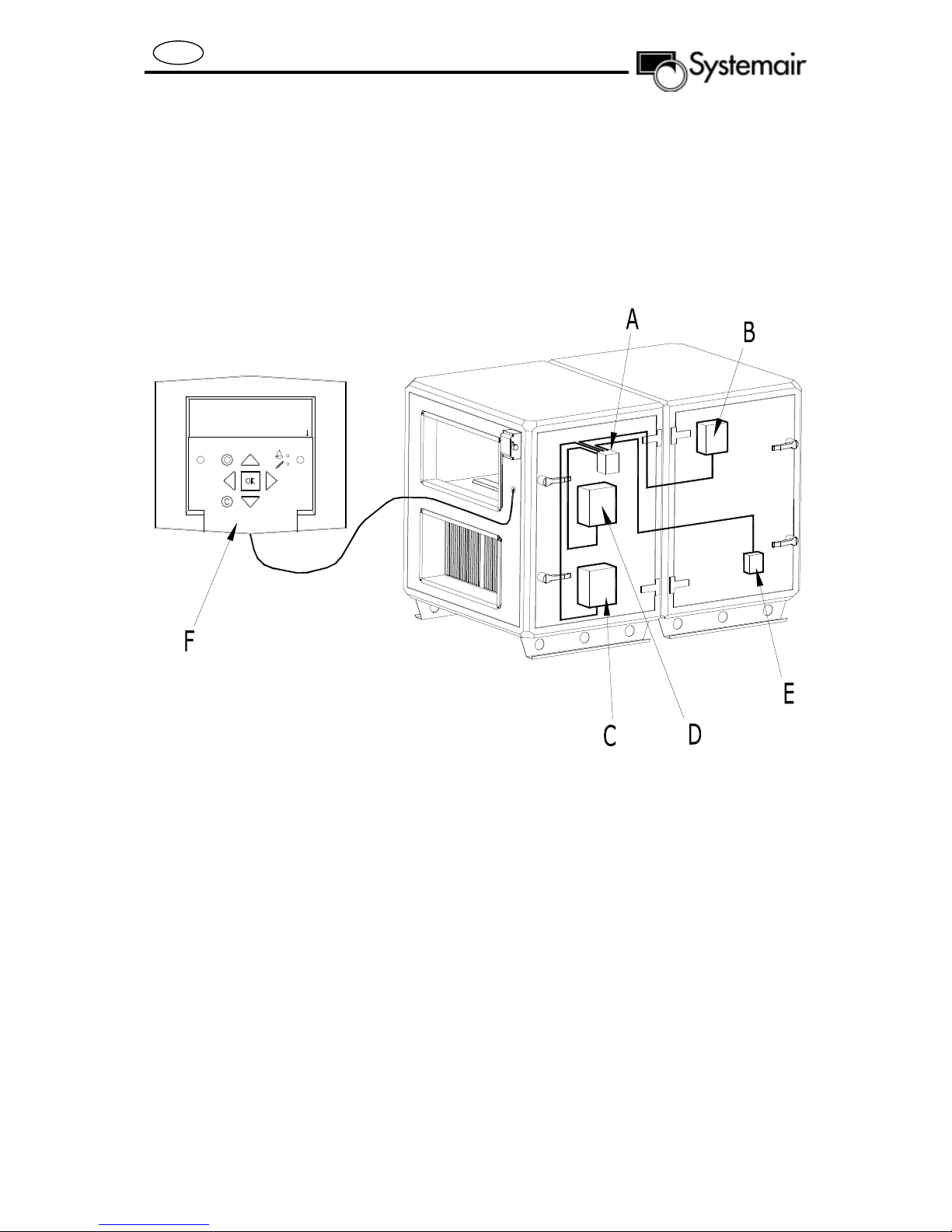
Automatic system/control
All ROTOVEX functions are controlled
from the Corrigo panel. For further
information refer to the supplied
Corrigo user manual.
Regulator vent. sys
05:05:30 15:45
System: Normal run
Sp: 18.0 Act: 17.8
A - Control box: Corrigo E28
B - Control box: rotor
C - Control box: supply air fan
D - Control box: exhaust air fan
E - Control box: electric heating
F – Control panel. Connects to a fast coupling inside
the connection box on the gable of the unit.
6
Page 7
GB
33/35
36/38
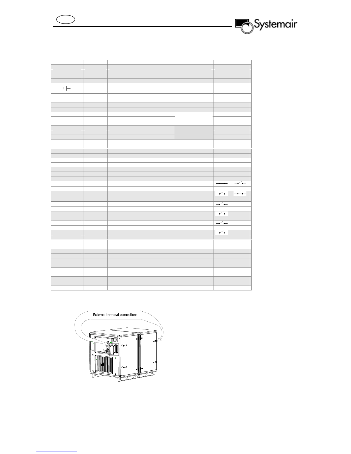
External connections
Terminal block Description Remark
13 G Valve actuator, supply voltage, Heating/cooling 24V AC
14 G0 Valve actuator, supply voltage, Heating/cooling Neutral
43 AO1 Control signal water heating 0-10V DC
57 AO3 Control signal water cooling 0-10V DC
PE Water pump, supply voltage. HW Heating Ground
45 N W ater pump, supply voltage. HW Heating Neutral
46 L1 Water pump, supply voltage. HW Heating 230V AC
39 DO6 Water pump, control voltage (contactor). Cooling 24V AC, 0,5A
G DO ref Water pump, control voltage (contactor). Cooling
33 DO2 Damper, exhaust air 24V AC, 0,5A
34 G0 Damper, exhaust air Neutral
35 G Damper, exhaust air 24V AC
36 DO1 Damper, fresh air 24V AC, 0,5A
37 G0 Damper, fresh air Neutral
38 G Damper, fresh air 24V AC
56 AI3 Extract air temperature sensor PT 1000
Agnd AI ref Extract air temperature sensor
27 UAI1 Fresh air temperature sensor PT 1000
Agnd UI ref Fresh air temperature sensor
31 AI4 Supply air temperature sensor PT 1000
32 AI ref Supply air temperature sensor
55 DO4 DX cooling, step1 24V AC, 0,5A
54 DO5 DX cooling, step2 24V AC, 0,5A
53 DO ref DX cooling, step1 and 2
*64 DI3 Run-indication/alarm circulation pump Cooling
*Ref DI DI ref Run-indication/alarm circulation pump Cooling
*47 DI5 Fire alarm
*Ref DI DI ref Fire alarm
*48 DI6 External stop
*Ref DI DI ref External stop
*49 DI7 Extended operation, Normal
*50 DI ref Extended operation, Normal
*59 DI8 External alarm
*Ref DI DI ref External alarm
40 DO7 Sum alarm, A- and B-alarm
G DO ref Sum alarm, A- and B-alarm
51 Net + LON
52 Net - LON
60 G Pressure transmitter, supply voltage 24V AC
61 AI1 Pressure transmitter, control signal. Supply air 0-10V DC
62 AI ref Pressure transmitter
63 AI2 Pressure transmitter, control signal. Extract air 0-10V DC
28 UAI2 Free to use
Agnd UI ref Free to use
58 UAI3 Free to use
Agnd UI ref Free to use
*Ref DI DI ref Is used together with UDI
* These inputs may only be wired to voltage free contacts.
By spring-loaded
damper, co nnect
By spring-loaded
damper, connect
or
or
All external connections are done in the connection boxes found on each end plate of
the unit. There is a sign on the inside illustrating the various functions and how they
are to be connected.
7
Page 8
GB
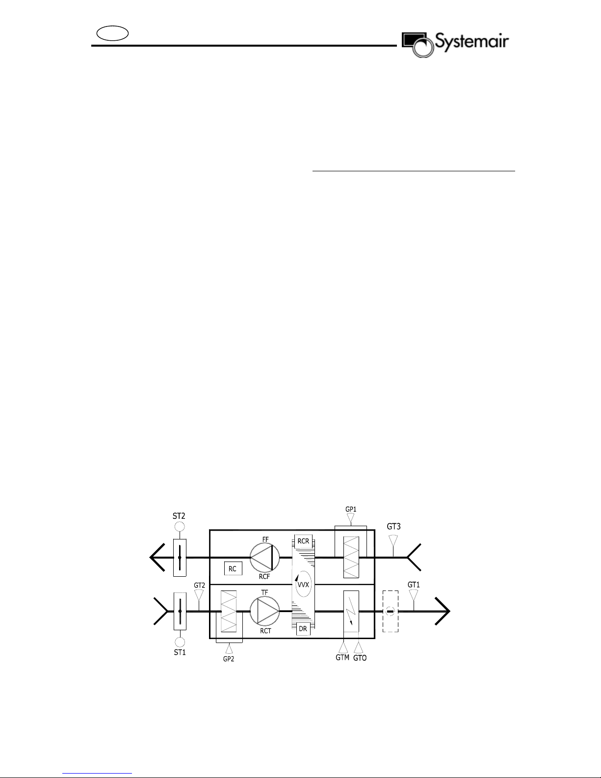
Description of functions
Electrical heating, extract air temperature
control with cascade function.
Function
Start and stop times are set in the
Control panel. To maintain constant
room temperature the RC receives a
signal from GT3 and regulates the VVX
and the electrical heater in sequence.
The GT1 sensor is used to limit the
max and min supply air temperature.
Maximum temperature in the electrical
re-heater is controlled by GTM. GTO
disconnects the heater, gives an alarm
signal and stops the appliance in case
of overheating.
ST1 closes the fresh air damper when
the appliance is stopped. In case of an
unintended stop on the rotor, the RCR
gives an alarm, which is displayed on
the Control panel as an alarm.
Also displayed in the Control panel are
date and time, operating status,
desired and actual room temperature.
GP1 and GP2 give alarm signals when
the actual value exceeds the pre-set
desired value for pressure drop over
the filter.
Designation Name
FF Exhaust air fan
TF Supply air fan
GT1 Sensor, supply air
GT2 Sensor, fresh air
GT3 Sensor, extract air
GTM Sensor, max temperature
in the electrical re-heater.
GTO Sensor overheating in
heater
GP1 Pressure guard, extract
air filter
GP2 Pressure guard, supply
air filter
RC Regulator Corrigo E28
RCF Control box: exhaust air
RCT Control box: supply air
RCR Control box for rotor
DR Motor, rotor
VVX Heat exchanger rotor
ST1 Damper, fresh air
ST2 Damper, exhaust air
8
Page 9
GB
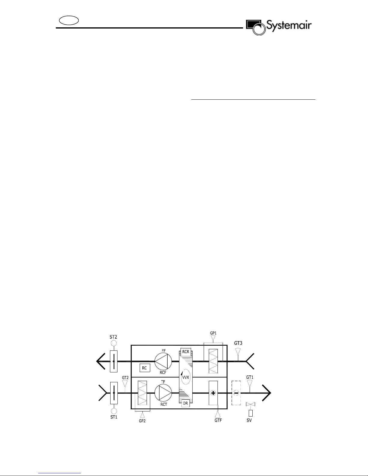
Description of functions
Water heating, extract air temperature
control with cascade function.
Function
Start and stop times are set in the
Control panel. To maintain constant
room temperature the RC receives a
signal from GT3 and regulates the VVX
and SV in sequence. The GT1 sensor
is used to limit the max and min supply
air temperature.
If there is a risk of frost in the water
heater SV opens completely.
If the temperature drops further, an
alarm is set off and the appliance
stops. GTF maintains constant water
temperature even when the fans have
stopped.
ST1 closes the fresh air damper when
the appliance stops. In case of an
unintended stop on the rotor, the RCR
gives an alarm, which is displayed on
the Control panel as an alarm.
Also displayed in the Control panel are
date and time, operating status,
desired and actual room temperature.
GP1 and GP2 give alarm signals when
the actual value exceeds the pre-set
desired value for pressure drop over
the filter.
Designation Name
FF Exhaust air fan
TF Supply air fan
GT1 Sensor, supply air
GT2 Sensor, fresh air
GT3 Sensor, extract air
GTF Sensor for frost protection
GP1 Pressure guard, extract
air filter
GP2 Pressure guard, supply
air filter
RCF Control box: exhaust air
RCT Control box: supply air
RC Regulator Corrigo E28
RCR Control box for rotor
DR Motor, rotor
VVX Heat exchanger rotor
SV Valve regulator, water
valve
ST1 Damper, fresh air
ST2 Damper, exhaust air
9
Page 10

GB
Starting up ROTOVEX
Instructions
In order to start up and run all the
functions the sensors and other
external attachments must be fitted.
Start the Rotovex by using the control
panel. Follow the instructions in the
Corrigo E – User Manual. Start with
chapter 6. Display, LEDs and buttons.
Set the menu language
Press the OK button while switching on
the mains supply.
Press the OK button. Choose language
with the UP / DOWN buttons. Confirm
the choice with the OK button.
Configuration/Settings
Refer to the Corrigo E – User Manual.
The unit is pre-set to constant airflow
and Extract air temperature control
with cascade function. Week schedule
is pre-set to Normal fan speed
between 07:00–16:00 Monday to
Sunday and stopped the rest of the
time.
For more detailed information see the
Commissioning record in the Operating
and Maintenance Instruction.
Important!
Do not forget to set the current time
and date.
10
Page 11
GB
Inspection and care of the fans
For inspection and care of the fans
open the front covers of the unit.
Important!
Disconnect the power supply before
opening the covers.
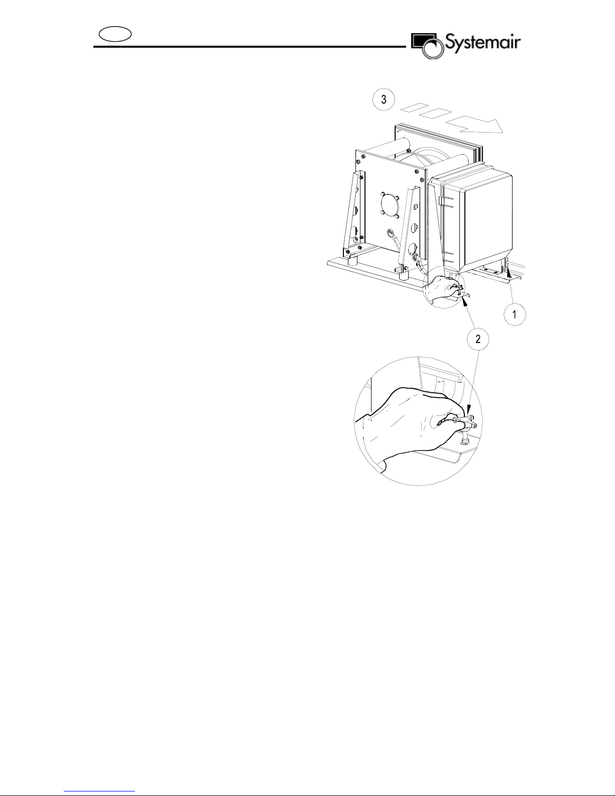
Fans
When cleaning or carrying out other
maintenance work where the fans
need to be removed, proceed as
follows:
1. Loosen all cable connectors and
pressure hoses
2. Loosen the lock nut at the foot
3. Pull out the fan cartridge
Proceed in the reverse order when
replacing the fan.
Push the fan cartridge in and make
sure that the lock nut is in place (fig 2).
Important!
DO NOT use water when cleaning the
inside of the unit.
11
Page 12

GB
Inspection and care of the
electrical heater
The heater is positioned in the same
section of the appliance as the rotor. It
is easy to remove for servicing or
cleaning. The connecting cables are
provided with quick connectors for
easy disconnection.
Regulating the heater
The power requirement for the heater
is adjusted according to the extract air
temperature, as set on the control
panel. The temperature is indicated
using a sensor in the extract air.
A Pulser regulates the power
requirements for the heaters.
ROTOVEX 2400 3000W 12000W
ROTOVEX 3800 4500W 15000W
ROTOVEX 4800 6000W 12000W
24000W
If the manual overheating protection for
the heater trips, it can be reset as
follows after the appliance has cooled
down:
1. Loosen the cable connectors
2. Pull out the heater until the
reset button is visible
3. Press the reset button
4. Push in the heater
5. Reconnect the cables
Position of the heater
12
Page 13

GB
Inspection and care of the water
heater
The heater is positioned in the same
section of the appliance as the rotor. It
is easy to access for installation of hot
water pipes.
When starting, the battery should be
bled using the air nipple on the collector to prevent air bubbles disturbing the
water flow. See figure below (A).
Regulating the heater
The power requirements for the heater
are adjusted according to the extract
air temperature, as set on the control
panel. The temperature is indicated
using a sensor in the extract air.
Position of the heater
Service and maintenance
The heater does not normally require
any service or maintenance. Check the
supply air side a couple of times a year
and clean if necessary.
Brush or vacuum the radiator. Take
great care when in contact with the
surface of the radiator, which must not
be deformed.
Heater power
ROTOVEX 2400 10000W
ROTOVEX 3800 15000W
ROTOVEX 4800 20000W
A – Venting device
B – Frost protection sensor
13
Page 14
GB
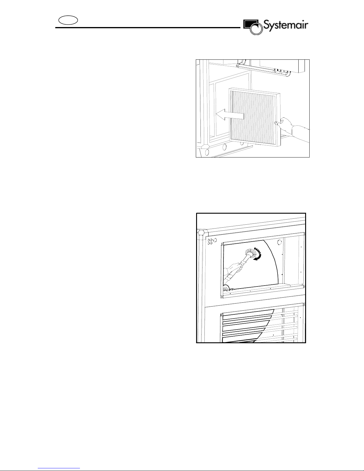
Inspection and care of filter
ROTOVEX is supplied with a class F7
supply air filter and class F5 exhaust
air filter. The filter is divided into 2
cassettes for ease of handling. The
filters are stretched with extensiblerails against sealing strips to minimise
leakage.
The filters are disposable and should
be replaced when the pressure drop
exceeds the given limit.
The filter can be ordered from
ROTOVEX suppliers or from
Systemair.
Inspection and care of rotating
heat exchanger
ROTOVEX is fitted with a rotating heat
exchanger. The rotor is made of
aluminium.
Service and maintenance
Clean the surface of the exchanger
using a vacuum cleaner with a brush
fitting. Take great care not to damage
the surface. Inspect and clean the heat
exchanger surface when changing the
filter, at least twice a year.
Clean using the exhaust air filter
space, turning the rotor by hand to
access the whole surface. If
necessary, compressed air may be
used to remove dirt.
If the transmission belt is worn or slack
it should be replaced. Contact
Systemair Service for help.
14
Page 15
GB
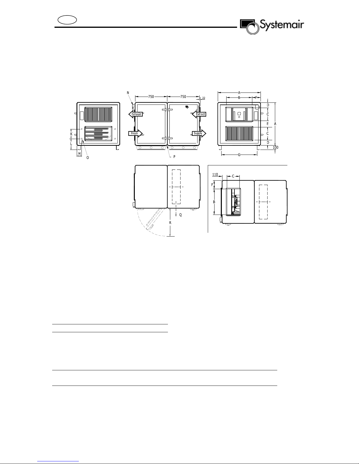
Measurements and specifications
Illustrations below are of a right-mounted version. The left-mounted version has the
inspection hatch on the opposite side. Duct connectors are rectangular, with
connection frame for joining guides.
For connection directed upward on exhaust air, see view below.
Systemair
Exhaust air connection upwards (Option)
N - Electrical connection through safety switch
O - Pipe connection for water heating, internal dimension 15 R (1/2”)
P - Appliance separates here
Q - Minimum space to enable rotor replacement = A-150
R - Minimum space for door 670 mm
Dimensions, heater connection
K L M
ROTOVEX 2400 337 210 145
ROTOVEX 3800 434 190 145
ROTOVEX 4800 487 190 145
Table of measurements
A
B
C
D
E
F
G
Weights
[kg]
ROTOVEX 2400 1000 600 300 125 150 200 795 300
ROTOVEX 3800 1120 600 400 108 104 260 915 340
ROTOVEX 4800 1230 800 400 135 165 215 1025 375
15
Page 16

GB
Damper (accessories)
Table of measurements
A
B
ROTOVEX 2400 600 300
ROTOVEX 3800 600 400
ROTOVEX 4800 800 400
Alarms
Alarm button (pos.1) opens the alarm
queue.
Press this button and active and nonacknowledged alarms will be displayed
in the menu window. The LED for
alarms (pos.2 ) is blinking if there are
non-acknowledged alarms and steady
if the alarms are still active but have
been acknowledged.
If there are multiple alarms use UP /
DOWN buttons to move between them.
An alarm can be acknowledged or
blocked by using OK and UP / DOWN
buttons. To abort and go back to start
menu select Cancel and press LEFT
button. For alarm settings see the
Commissioning protocol.
Extra stop function
For some alarm types such as electric
heating high temperature limit and
water heating frost protection it would
Damper option:
1. Two position actuator
2. Spring return actuator
The damper is intended for closing
the fresh air/exhaust air connections.
Standard air tightness class
be dangerous to not stop the unit on
alarm. Therefore, for such alarm types,
the program will always reset the stop
function to Active even if the operator
should choose Inactive.
It is unfortunately not possible to
remove the display text concerning the
stop function for these alarm types.
This since the available program space
demands that all alarms are treated in
the same way in the display.
16
Page 17

GB
Commissioning record
Company
Responsible
Customer Date Installation
Object / Unit Item no. Installation address
Model / size Series no.
Present time and date set. Week schedule set.
External connections such as sensors, dampers, external alarms etc. done.
Function
Temperature (°C).
Control function Temp.
Set point
Outdoor compensating
(supply air controlling)
Outdoor / supply temp.
Min. supply set point
Max. supply set point
Switching point, between
supply and cascade
regulating
Air flow
Fan regulation
Point 1,2 and 3
Point 4,5 and 6
Point 7 and 8
Preset value Set value
Supply Exhaust Room
18,0 °C
-30,0 / 22,0 -20,0 / 21,0 -11,0 / 20,5
-4,0 / 20,0 5,0 / 19,5 12,5 / 19,0
21,0 / 18,5 30,0 / 18,0
12,0 °C
30,0 °C
13,0 °C
Airflow (m3/h)
Pressure (Pa)
CO2 (ppm)
Supply Exhaust Room
°C
/
/
/
°C
°C
°C
Airflow (m3/h)
Pressure (Pa)
CO2 (ppm)
/
/
/
/
/
Set point Normal
Set point Reduced
Outdoor compensation
Supply fan
Supply fan
Lower point -20.°C 0 .m3/h, Pa
Upper point 10.°C 0 .m3/h, Pa
Only reduced fan speed
when outdoor is below.
Rotovex 2400 * 2300 m3/h or 250Pa ** 2300 m3/h or 250Pa *** 1500 m3/h or 100Pa **** 1500 m3/h or 100Pa
Rotovex 3800 * 3500 m3/h or 250Pa ** 3500 m3/h or 250Pa *** 2000 m3/h or 100Pa **** 2000 m3/h or 100Pa
Rotovex 4800 * 4500 m3/h or 250Pa ** 4500 m3/h or 250Pa *** 2500 m3/h or 100Pa **** 2500 m3/h or 100Pa
-20 °C °C
17
* .
Extract fan
***.
Extract fan
** .
Supply fan
Supply fan
****.
Extract fan
Extract fan
Lower point °C m3/h, Pa
Upper point °C m3/h, Pa
Page 18

GB
Function Preset value Set value
Cooling
Control function cooling
On/off function
Number of binary steps 1 2 3 1 2 3
Lowering of min. control
temp. supply air, DX cooling
Humidity
Control function
humidification.
Sensors
(0-10V DC for 0-100% RH)
Set point
Max. limit (duct sensor) 80. % RH % RH
Week scheduler settings
Preset week schedule is:
Period 1. 07:00-16:00 Monday-Sunday, normal fan-speed.
Period 2. 00:00-00:00 Monday-Sunday. 00:00-00:00 inactivates the period.
Weekday Period Normal Reduced
Not active 0-10V On/off
Mon. 1
2
Thu. 1
2
Wed. 1
2
Thurs. 1
2
Fri. 1
2
Sat. 1
2
Sun. 1
2
Holidays (month.day) Holidays (month.day) Holidays (month.day) Holidays (month.day)
1step 2step 3step binary step
5,0 . °C °C
Disable
Humidification
De-humidification
Humidification / De-humidification
Room sensor
Room and Duct sensor (max limiting)
50. % RH % RH
: - : : - :
: - : : - :
: - : : - :
: - : : - :
: - : : - :
: - : : - :
: - : : - :
: - : : - :
: - : : - :
: - : : - :
: - : : - :
: - : : - :
: - : : - :
: - : : - :
Not active 0-10V On/off
1step 2step 3step binary step
Disable
Humidification
De-humidification
Humidification / De-humidification
Room sensor
Room and Duct sensor (max limiting)
1. . - . 7. . - . 13. . - . 19. . - .
2. . - . 8. . - . 14. . - . 20. . - .
3. . - . 9. . - . 15. . - . 21. . - .
4. . - . 10. . - . 16. . - . 22. . - .
5. . - . 11. . - . 17. . - . 23. . - .
6. . - . 12. . - . 18. . - . 24. . - .
18
Page 19

GB
Function Preset value Set value
Frost Protection
Mode (EL unit Off): On On Off
Frost limit temperature:
Set point when stopped:
(return water)
P-band when running:
Pressure Input
Supply/Exhaust Air Fan
Supply Air Fan Pressure at 0V
Supply Air Fan Pressure at 10V
Exhaust Air Fan Pressure at 0V
Exhaust Air Fan Pressure at 10V
Night cooling
Mode: Off On Off
Run when day outdoor temp is
higher than:
Stop when night outdoor temp is
higher than:
Stop when night outdoor temp is
lower than:
Stop when room temp is lower
than:
See Alarm settings/
Low frost guard temp
10. °C °C
5.
0. (Pa)
CAV 1600 Pa VAV 500 Pa
0. (Pa)
CAV 1600 Pa VAV 500 Pa
22. °C °C
15. °C °C
5. °C °C
18. °C °C
See Alarm settings/
Low frost guard temp
(Pa)
(Pa)
(Pa)
(Pa)
Cool Recycling
Mode: Off On Off
Start Limit: 2. °C °C
Control On Demand
Min time for control on demand: 60. min min
Support control: Off On Off
Run Exhaust Air Fan when support
control active
CO2 control Off
CO2 control Type Damper
On On Off
On when active time channel
On when in-active time channel
On
Fan
Off
On when active time channel
On when in-active time channel
On
Damper
Fan
19
Page 20

GB
Function Preset value Set value
Fire Function
Fire damper function: Off
Extraction when fire alarm: Off On Off
Fire input: Normally opened
Fire damper exercise: No exercise
Fire damper run time: 90. s s
Fire damper interval: 1. days days
Fire damper exercise hour 0. h h
Mixing damper Min Limitation
Mode: Off On Off
Limit: 5. %
External Set point Knob
External set point knob: Off
Damper normally closed
Damper normally opened
Normally closed
Exercise with
ventilation running
Exercise with
ventilation stopped
Off
Damper normally closed
Damper normally opened
Normally opened
Normally closed
No exercise
Exercise with
ventilation running
Exercise with
ventilation stopped
%
On Off
Min set point of knob: 12. °C
Max set point of knob: 30. °C
Heat Pump (HW unit)
Pump stop mode (EL unit Off): On
Pump stop delay: 5. min
Stop pump at temp: 10. °C
Pump stop hysteretic: 1. °C
Pump exercise hour: 15.
Cool Pump
Pump stop delay 5. min
General
Heat Pump Indication
Cool Pump Indication
Outdoor Temperature Related
Settings
Full heat when outdoor temp is
below
Motor Protection
Run Indication
Motor Protection
Run Indication
3. °C °C
°C
°C
On Off
min
°C
°C
min
Motor Protection
Run Indication
Motor Protection
Run Indication
20
Page 21

GB
Function Preset value Set value
Miscellaneous
Extended operation
Min. set point reduction, Supply
air. At DX-Cooling:
60. min
5. °C
min
°C
Alarm configuration.
Alarm settings
1. Supply Air Fan is out of operation 26. Sensor error
Stop ventilation unit if alarm active No Stop ventilation unit if alarm active No
2. Exhaust Air Fan is out of operation 28. Rotation guard exchanger
Stop ventilation unit if alarm active No Stop ventilation unit if alarm active No
3. P1-Heater is out of operation 29. Fire damper is out of operation
(Applies to HW units) Class B Class B
Stop ventilation unit if alarm active No Stop ventilation unit if alarm active No
4. P1-Cooler is out of operation 30. Supply Air Fan Pressure control error
Stop ventilation unit if alarm active No Stop ventilation unit if alarm active No
6. Filter guard 31. Exhaust Air Fan Pressure control error
Stop ventilation unit if alarm active No Stop ventilation unit if alarm active No
8. External frost guard 32. Supply Air Fan external operation
Stop ventilation unit if alarm active Yes Stop ventilation unit if alarm active No
10. Fire alarm 33. Exhaust Air Fan external operation
Stop ventilation unit if alarm active Yes Stop ventilation unit if alarm active No
11. External switch 34. Ventilation stopped
Stop ventilation unit if alarm active Yes Stop ventilation unit if alarm active No
12. External alarm 35. Manual supply air control
Stop ventilation unit if alarm active No Stop ventilation unit if alarm active No
13. Supply Air control error 36. Manual Supply Air Fan mode
Stop ventilation unit if alarm active No Stop ventilation unit if alarm active No
Max diff between set point and supply 5 °C
14. High supply air temp 37. Manual Supply Air Fan freq control
Stop ventilation unit if alarm active No Stop ventilation unit if alarm active No
High supply air temp 35 °C
15. Low supply air temp 38. Manual Exhaust Air Fan mode
Stop ventilation unit if alarm active Yes Stop ventilation unit if alarm active No
Low supply temp 10 °C
Preset
value
Class B Class B
Delay 300 s
Class B Class B
Delay 300 s
Delay 5 s
Class B Class B
Delay 5 s
Class B Class B
Delay 300 s
Class Off Class Off
Delay 0 s
Class A Class Off
Delay 0 s
Class C Class C
Delay 0 s
Class B Class C
Delay 0 s
Class B Class C
Delay 4 min
Class B Class C
Delay 300 s
Class A Class C
Delay 300 s
Set
value
Alarm settings
Max diff between set point and actual pressure
Max diff between set point and actual pressure
Preset
value
Delay 5 s
Delay 60 s
Delay 90 s
Delay 4 min
50 Pa
Delay 4 min
50 Pa
Delay 120 s
Delay 120 s
Delay 0 s
Delay 0 s
Delay 0 s
Delay 0 s
Delay 0 s
Set
value
21
Page 22

GB
Alarm settings
18. High room temp 39. Manual Exhaust Air Fan freq control
Stop ventilation unit if alarm active No Stop ventilation unit if alarm active No
High room temp 30 °C
19. Low room temp 40. Manual heater control
Stop ventilation unit if alarm active No Stop ventilation unit if alarm active No
Low room temp 10 °C
20. High exhaust air temp 41. Manual cooler control
Stop ventilation unit if alarm active No Stop ventilation unit if alarm active No
High exhaust temp 30 °C
21. Low exhaust air temp 42. Manual exchanger control
Stop ventilation unit if alarm active No Stop ventilation unit if alarm active No
Low exhaust temp 10 °C
22. Electric heating is overheated 43. Manual P1-Heater
(Set to Off on HW units) Class A (Applies to HW units) Class C
Stop ventilation unit if alarm active Yes Stop ventilation unit if alarm active No
23. Frost risk 44. Manual P1-Cooler
(Set to Off on EL units) Class B Class C
Stop ventilation unit if alarm active No Stop ventilation unit if alarm active No
24. Low frost guard temp 46. Manual fire damper
(Applies to HW units) Class A Class B
Stop ventilation unit if alarm active Yes Stop ventilation unit if alarm active No
Frost limit 7 °C
25. Low efficiency 47. Internal battery error
Stop ventilation unit if alarm active No Stop ventilation unit if alarm active No
Low efficiency 50 %
Preset
value
Class B Class C
Delay 30 min
Class B Class C
Delay 30 min
Class B Class C
Delay 30 min
Class B Class C
Delay 30 min
Delay 0 s
Delay 60 s
Delay 0 s
Class Off Class A
Delay 30 min
Set
value
Alarm settings
Preset
value
Delay 0 s
Delay 0 s
Delay 0 s
Delay 0 s
Delay 0 s
Delay 0 s
Delay 0 s
Delay 0 s
Set
value
In/Output Configurations.
Possible choices of
Analogue input signal
Outdoor temperature sensor UAI 1
Supply air temperature sensor AI 4
Exhaust air temperature sensor AI 3
Extract temperature sensor
Room temperature sensor 1
Room temperature sensor 2
CO2 / VOC sensor 0…10V DC
Extra sensor / Set point potentiometer
Pressure transmitter, supply air 0…10V DC AI 1
Pressure transmitter, exhaust air 0…10V DC AI 2
De-icing sensor, heat exchanger
Frost protection sensor, Hot water heater.
Room Humidity sensor
Duct Humidity sensor
Preset
Configuration
UAI 4
(HW units)
22
Set
Configuration
Page 23

GB
Possible choices of
Analogue output signal
Y1 Actuator Heating AO 1
Y2 Actuator Exchanger AO 2
Y3 Actuator Cooling AO 3
Frequency converter, supply air fan AO 4
Frequency converter, exhaust air fan AO 5
Actuator Humidity control
Split of any one of temp outputs Y1,Y2 or Y3
Possible choices of
Digital input signal
Filter guard, supply air and exhaust air DI 1
Run-indication/alarm circulation pump, heating
Run-indication/alarm circulation pump, cooling DI 3
Run-indication/alarm circulation pump, exchanger
Fire alarm DI 5
Fire damper end-switch monitoring
Extended Operation, Normal DI 7
Extended Operation, Reduced
External stop DI 6
External alarm DI 8
Flow-switch
Rotation sentinel, exchanger DI 4
Run-indication/alarm supply air fan
Run-indication/alarm exhaust air fan
De-icing, exchanger
Frost protection thermostat
Overheated electric heater
Preset
Configuration
Preset
Configuration
DI 2
(HW units)
UDI 4
(EL units)
Set
Configuration
Set
Configuration
Possible choices of
Digital output signal
Start/stop supply air fan (SAF) 1/1-speed DO 1
Start/stop exhaust air fan (EAF) 1/1-speed DO 2
Start/stop supply air fan (SAF) 1/2-speed
Start/stop exhaust air fan (EAF) 1/2-speed
Start/stop circulation pump, heating
Fire dampers
Sum alarm A- and B-alarm DO 7
Sum alarm A-alarm
Sum alarm B-alarm
Start/stop circulation pump,cooling DO 6
Start/stop circulation pump, liquid exchanger
Activation-signal SAF frequency converter
Activation-signal EAF frequency converter
Activation heating
Activation cooling
Activation heat exchanger
Preset
Configuration
DO 3
(HW units)
DO 3
(EL units)
Set
Configuration
23
Page 24

GB
Possible choices of
Digital output signal
Extract air close-off damper
Fresh air close-off damper
Re-circulation damper
Heating 3-pos. actuator, increase
Heating 3-pos. actuator, decrease
Exchanger 3-pos. actuator, increase
Exchanger 3-pos. actuator, decrease
Cooling 3-pos. actuator, increase
Cooling 3-pos. actuator, decrease
Step controller heating, step 1
Step controller heating, step 2
Step controller heating, step 3
Step controller heating, step 4
Step controller cooling, step 1 DO 4
Step controller cooling, step 2 DO 5
Step controller cooling, step 3
Extra Timer channel 1
Extra Timer channel 2
Extra Timer channel 3
Extra Timer channel 4
Extra Timer channel 5
Notes
Preset
Configuration
Set
Configuration
24
Page 25

SE
Innehållsförteckning
Sida
26 Tillverkardeklaration
27 Elektrisk anslutning
28 Kontrollera efter anslutning
29 Automatik/styrning
30 Externa förbindningar
31 Funktionsbeskrivning/elvärme
32 Funktionsbeskrivning/vattenvärme
33 Start och inställning av ROTOVEX
34 Inspektion och tillsyn av fläktar
35 Inspektion och tillsyn av el värmare
36 Inspektion och tillsyn av vattenvärmare
37 Inspektion och tillsyn av filter och rotor
38 Mått och viktuppgifter
39 Larmfunktioner, spjäll
41 Konfigurering Corrigo
Not. Systemair AB förbehåller sig rätten att utan föregående information göra ändringar och
förbättringar till innehållet i denna manual.
25
Page 26

SE
Tillverkare
Våra produkter är tillverkade i enlighet med gällande
EU-direktiv.
Tillverkaren försäkrar härmed att följande produkter:
Luftbehandlingsaggregat
Rotovex 2400HW Rotovex 2400 EL, Rotovex
3800 HW, 3800 EL, Rotovex 4800 HW, Rotovex
4800 EL.
överensstämmer med kraven i nedanstående EUdirektiv.
Systemair AB
Industrivägen 3
739 30 Skinnskatteberg
Tel: 0222-440 00
Fax: 0222-440 99
EU-försäkran om överensstämmelse
enligt EUs maskindirektiv 98/37/EEC, bilaga IIA.
Aggregat för ventilation i luftbehandlingssystem
grupp A med luft från icke explosionsfarligt utrymme
(ELSÄK-FS 1999:5 830.1, 830.3).
Fläktar får ej tas i bruk innan installationsanvisning
och säkerhetsanvisning har beaktats.
Harmoniserade standarder:
EN 60 034-1
Roterande elektriska maskiner; märkdata och
driftsegenskaper
EN 60 204-1
Maskinsäkerhet; elutrustning för maskiner: allmänna
fordringar.
EN 292-1
Maskinsäkerhet; grundläggande begrepp; allmänna
konstruktionsprinciper.
EN 294
Maskinsäkerhet; skyddsavstånd för att hindra att
man når riskområden med händer och armar.
Anmärkning: Överensstämmelsen med EN 294
avser endast monterade skyddsutrustningar
EU-försäkran om överensstämmelse
enligt EUs lågspänningsdirektiv 73/23/EEC och
93/68/EEC
Harmoniserade standarder:
EN 60 335-1
Elektriska hushållsapparater och liknande
bruksföremål- Säkerherhet-Allmänna fordringar.
EN 60 335-2-40 Elektriska hushållsapparater och
liknande bruksföremål - Säkerhet - Del 2: Särskilda
fordringar på elektriska värmepumpar,
Internationella standarder
EN 50 106
Elektriska hushållsapparater och liknande
bruksföremål-Säkerhet-Anvisningar för
tillverkningskontroll.
Anmärkning: Överensstämmelse med EN 50 106
gäller kopplade produkter.
EU-försäkran om överensstämmelse
enligt EUs EMC-direktiv 89/336/EEC, 92/31/EEC
och 93/68/EEC
Harmoniserade standarder:
EN 61000-6-4 Elektromagnetisk kompatibilitet
(EMC) - Del 6-4: Generella fordringar - Emission
från utrustning i industrimiljö.
EN 61000-6-2 Elektromagnetisk kompatibilitet
(EMC)- Del 6-2: Generella fordringar-Immunitet hos
utrustning i industrimiljö.
Komplett teknisk dokumentation finns tillgänglig.
Skinnskatteberg, 06 Feb 2003
Mats Sándor
Teknisk chef
26
Page 27

SE
Elektrisk anslutning
Aggregatet får ej tas i drift innan
samtliga el-tekniska och mekaniska
säkerhetsanordningar anbringats.
Elektrisk anslutning av ROTOVEX sker
genom fast nätanslutning av den låsbara säkerhetsbrytaren på aggregatgaveln, se bilden.
Elektrisk märkdata och tillverkningsnummer för aggregatet, se märkskylten
som sitter under säkerhetsbrytaren.
Om aggregatet är utrustad med värmare som kräver extern kraftmatning (se
tabell nedan). Skall den förses med en
arbetsbrytare för att servicearbeten
skall kunna utföras, se bild.
En allpolig brytare med 3 mm brytavstånd måste användas vid fast
installation.
Elektriska data för aggregatet:
Rotovex Nät Aggregat (A) Värmare [kW]
2400HW 230V1~ 5,5 *10,0 2400EL 400V3N~ 10,0 3,0 2400EL 400V3N~ 5,5 **12,0 **17,5
2400EL 230V3~ 5,5 **12,0 **30
3800HW 400V3N~ 6,0 *15,0 3800EL 400V3N~ 12,5 4,5 3800EL 400V3N~ 6,0 **15,0 **22
3800EL 230V3~ 6,0 **15,0 **38
4800HW 400V3N~ 8,5 *20,0 4800EL 400V3N~ 17,0 6,0 4800EL 400V3N~ 8,5 **12,0 **17,5
4800EL 400V3N~ 8,5 **24,0 **35
4800EL 230V3~ 8,5 **12,0 **30
4800EL 230V3~ 8,5 **24,0 **60
*Vid värmevatten in/ut 55/40°C
**El värmare (över 6 KW) har separat matning. För 230V3~ behövs en transformator
(230V3~ till 400V3~) för matning till aggregatet.
Värmare med separat
kraftmatning [A]
27
Page 28

SE
Kontrollera efter anslutning
• Rotationsriktning fläkthjul
Kontrollera fläkthjulens
rotationsriktning.
• Spjäll
Kontrollera att spjällen stänger och
öppnar korrekt.
• Ställdon/styrventil värmevatten
Kontrollera att ventilen stänger och
öppnar korrekt.
• Tryck/Temperaturer
Kontrollera att inställda värden på luftflöden och temperaturer är korrekta.
• Filter sluttryckfall
Kontrollera att tryckgivarna vid filtren är
inställda på rätt sluttryck = larmläge.
Rekommenderat sluttryck ca: 240 Pa.
28
Page 29

SE
Automatik/styrning
All manövrering av ROTOVEX
funktioner sker från Kontroll panelen.
För information om handhavandet, se
Corrigo användarmanual.
Regulator vent. sys
05:05:30 15:45
System: Normal run
Sp: 18.0 Act: 17.8
A - Reglercentral: Corrigo E28
B - Reglercentral: rotor
C - Reglercentral: tilluftsfläkt
D - Reglercentral: frånluftsfläkt
E - Reglercentral: el-värme
F – Kontroll Panel. Ansluts inuti
kopplings boxen (snabbkontakt) på
aggregatets gavel.
29
Page 30

SE
Externa förbindningar
Kopplingsplint Beskrivning Anmärkning
13 G Ventilställdon, matarspänning. Värme/kyla 24V AC
14 G0 Ventilställdon, matarspänning. Värme/kyla Nolla
43 AO1 Styrsignal hetvatten batteri 0-10V DC
57 AO3 Styrsignal kallvatten batteri 0-10V DC
PE Vatten pump, matarspänning. Hetvatten batteri Jord
45 N Vatten pump, matarspänning. Hetvatten batteri Nolla
46 L1 Vatten pump, matarspänning. Hetvatten batteri 230V AC
39 DO6 Vatten pump, styrspänning (kontaktor). Kallvatten batteri 24V AC, 0,5A
G DO ref Vatten pump, styrspänning (kontaktor). Kallvatten batteri
33 DO2 Avluft spjäll 24V AC, 0,5A
34 G0 Avluft spjäll Nolla
35 G Avluft spjäll 24V AC
36 DO1 Uteluft spjäll 24V AC, 0,5A
37 G0 Uteluft spjäll Nolla
38 G Uteluft spjäll 24V AC
56 AI3 Givare, Frånluft temperatur PT 1000
Agnd AI ref Givare, Frånluft temperatur
27 UAI1 Givare, Uteluft temperatur
Agnd UI ref Givare, Uteluft temperatur
31 AI4 Givare, Tilluft temperatur PT 1000
32 AI ref Givare, Tilluft temperatur
55 DO4 DX kyla, steg1 24V AC, 0,5A
54 DO5 DX kyla, steg2 24V AC, 0,5A
53 DO ref DX kyla, steg1 och 2
*64 DI3 Driftindikering/larm cirkulationspump, Kyla
*Ref DI DI ref Driftindikering/larm cirkulationspump, Kyla
*47 DI5 Brandlarm
*Ref DI DI ref Brandlarm
*48 DI6 Extern brytare
*Ref DI DI ref Extern brytare
*49 DI7 Förlängd drift, Normal hastighet
*50 DI ref Förlängd drift, Normal hastighet
*59 DI8 Externt larm
*Ref DI DI ref Externt larm
40 DO7 Summalarm, A- och B-larm
G DO ref Summalarm, A- och B-larm
51 Net + LON
52 Net - LON
60 G Tryckgivare, matarspänning 24V AC
61 AI1 Tryckgivare, styrsignal. Tilluft 0-10V DC
62 AI ref Tryckgivare
63 AI2 Tryckgivare, styrsignal. Frånluft 0-10V DC
28 UAI2 Ledig
Agnd UI ref Ledig
58 UAI3 Ledig
Agnd UI ref Ledig
*Ref DI DI ref Används som referens tillsammans med UDI
* Dessa ingångar får endast anslutas till spänningsfria kontakter.
Med fjäderretur
spjäll, anslu t 33/35
Med fjäderretur
spjäll, anslut 36/38
PT 1000
eller
eller
All extern inkoppling sker till kopplingsboxarna, placerade på aggregatets båda
kortsidor, där också inkopplingsinstruktion med funktionsbeskrivning finns att tillgå.
30
Page 31

SE
Funktionsbeskrivning
Elvärme, kaskadkopplad frånlufts
temperatur reglering.
Funktion
Start/stopp sker via inprogrammerad
tid i Kontroll panelen. Konstanthållning
av rums-temperaturen sker genom att
RC via signal från GT3, styr VVX och
el-värmaren i sekvens. GT1 givaren
används för max och min begränsning
av tillufttemperaturen. Max
begränsning av temperaturen i elvärmaren styrs av GTM. GTO bryter
strömmen till värmaren vid
överhettning, ger larm och stoppar
aggregatet.
ST1 stänger uteluftsspjället vid stoppat
aggregat. Vid ofrivilligt stopp av rotorn
larmar RCR. Larmet avläses på
Kontroll panelen.
På Kontroll panelen visas även Datum
och tid, driftläge, önskad och verklig
rums temperatur.
GP1 och GP2 larmar när ärvärdet
överstiger inställt börvärde på tryckfallen över filtren.
Beteckning Benämning
FF Frånluftsfläkt
TF Tilluftsfläkt
GT1 Givare tilluft
GT2 Givare uteluft
GT3 Givare frånluft
GTM Givare max temperatur el-
värmare
GTO Givare övertemperatur
skydd el-värmare
GP1 Tryckvakt frånluftsfilter
GP2 Tryckvakt tilluftsfilter
RC Reglercentral Corrigo E28
RCF Reglercentral frånluftsfläkt
RCT Reglercentral tilluftsfläkt
RCR Reglercentral rotordrivning
DR Drivmotor, rotor
VVX Värmeväxlare (rotor)
ST1 Spjällställdon uteluft
ST2 Spjällställdon avluft
31
Page 32

SE
Funktionsbeskrivning
Vattenvärme, kaskadkopplad frånlufts
temperatur reglering.
Funktion
Start/stopp sker via inprogrammerad
tid i Kontroll panelen. Konstanthållning
av Rums-temperaturen sker genom att
RC via signal från GT3, styr VVX och
SV steglöst, i sekvens. GT1 givaren
används för max och min begränsning
av tillufttemperaturen.
Vid frysrisk i vattenvärmaren öppnar
SV helt. Om temperaturen sjunker
ytterligare ges larm och aggregatet
stoppas. GTF konstanthåller vattentemperaturen även när fläktarna har
stannat.
ST1 stänger uteluftsspjället vid stoppat
aggregat. Vid ofrivilligt stopp av rotorn
larmar RCR. Larmet avläses på
Kontroll panelen.
På Kontroll panelen visas även Datum
och tid, driftläge, önskad och verklig
rums temperatur.
GP1 och GP2 larmar när ärvärdet
överstiger inställt börvärde på tryckfallen över filtren.
Beteckning Benämning
FF Frånluftsfläkt
TF Tilluftsfläkt
GT1 Givare tilluft
GT2 Givare uteluft
GT3 Givare frånluft
GTF Givare frysskydd
GP1 Tryckvakt frånluftsfilter
GP2 Tryckvakt tilluftsfilter
RCF Reglercentral frånluftsfläkt
RCT Reglercentral tilluftsfläkt
RC Reglercentral Corrigo E28
RCR Reglercentral rotordrivning
DR Drivmotor, rotor
VVX Värmeväxlare (rotor)
SV Ställdon vattenventil
ST1 Spjäll ställdon uteluft
ST2 Spjäll ställdon avluft
32
Page 33

SE
Start och inställning av ROTOVEX
Instruktioner
För att kunna starta och köra alla
funktioner ska aggregatets givare och
övrig extern utrustning vara monterad.
Starta upp aggregatet via Kontroll
panelen. Följ anvisningarna i Corrigo E
– Manualen. Starta med kapitel 6.
Display, lysdioder och knappar.
Ställa in meny språk
Håll in OK knappen samtidigt som
matningsspänningen slås på.
Tryck på OK knappen. Välj önskat
språk med UPP / NER knapparna och
bekräfta valet med OK knappen.
Konfigurering/inställningar
Se Corrigo E – Manualen och
Igångkörnings protokoll i Drift och
skötsel anvisningen.
Aggregatet är från fabrik förinställt för
konstantflödes reglering och Frånluft
temperatur reglering med kaskad
funktion.
Veckoschemat är förinställt till Normal
fläkthastighet mellan 07:00-16:00
måndag till söndag och stoppat resten
av tiden.
Viktigt!
Glöm inte att ställa tiduret med aktuell
dag och klockslag.
33
Page 34

SE
Inspektion och tillsyn av fläktar
För inspektion och tillsyn av komponenter i aggregatet öppnas frontluckorna.
Viktigt!
Aggregatet ska vara strömlöst innan
luckorna öppnas.
Fläktarna
Vid rengöring eller annat servicearbete
där fläkten behöver tas ut ska följande
moment utföras:
1. Lossa alla kabelkontakter och
tryckslangar till fläkten
2. Lossa låsratten vid foten
3. Drag ut fläktpaketet
Vid återmontering omvända ordningen.
Skjut in fläktpaketet och se till att sätta
dit låsratten ordentligt på plats (fig. 2).
Viktigt!
Vid rengöring invändigt i aggregatet får
vatten INTE användas.
34
Page 35

SE
Inspektion och tillsyn av
elvärmare
Värmaren är placerad i samma aggregatdel som rotorn. Den är lätt demonterbar för service eller rengöring.
Anslutna kablage är försedda med
kontaktdon för snabb hantering.
Reglering värmare
Värmarens effektbehov anpassas efter
den frånluftstemperatur som ställs in
på kontroll panelen. Temperaturen
indikeras via givaren i frånluften.
Värmarens effektbehov styrs av en
Pulser.
Värmarnas effekt
ROTOVEX 2400 3000W 12000W
ROTOVEX 3800 4500W 15000W
ROTOVEX 4800 6000W 12000W
24000W
Om värmarens manuella överhettningsskydd löst ut, återställs detta
enligt följande, när elementen kallnat:
1. Lossa kablagekontakterna
2. Drag ut värmaren tills
återställningsknappen blir synlig
3. Tryck in återställningen
4. Skjut in värmaren
5. Återmontera kablagekontakterna
Placering av värmare
35
Page 36

SE
Inspektion och tillsyn av
vattenvärmare
Värmaren är placerad i samma aggregatdel som rotorn. Den är lätt åtkomlig
för installation av anslutande värmevattenrör.
Vid start ska batteriet luftas vid luftnippeln på ena samlingsröret för att
förhindra att luftblåsor stör vattenflödet,
se bild nedan (A).
Reglering värmare
Värmarens effektbehov anpassas efter
den frånluftstemperatur som ställs in
på kontroll panelen. Temperaturen
indikeras via givaren i frånluften.
Placering av värmare
Service och underhåll
Värmaren behöver som regel ingen
service eller underhåll. Inspektera
tilluftssidan ett par gånger om året och
rengör vid behov.
Borsta eller dammsug lamellytan.
Iakttag stor försiktighet vid beröring av
ytan, lamellerna får inte deformeras.
Värmarnas effekt
ROTOVEX 2400 10000W
ROTOVEX 3800 15000W
ROTOVEX 4800 20000W
A – Luftningsnippel
B – Frysskyddsgivare
36
Page 37

SE
Inspektion och tillsyn filter
ROTOVEX är från leverans utrustad
med tilluftsfilter klass F7 och frånluftsfilter i klass F5. Filtren är delade i två
kassetter för enkel hantering. Tätning
av filtren med utdragbar plåtskena och
tätningslister för att minimera läckage.
Filtren är avsedda för engångsbruk och
ska bytas när tryckfallet överstiger
angivet tryckgränsvärde.
Filtren beställes hos ROTOVEXåterförsäljaren eller Systemair.
Inspektion och tillsyn roterande
värmeväxlare
ROTOVEX är utrustad med roterande
värmeväxlare. Rotorn är tillverkad av
aluminium.
Service och underhåll
Växlarens yta rengöres genom dammsugning av ytan med borstmunstycke.
Stor försiktighet iakttas vid beröring av
rotorytan för att undvika skador.
Inspektion och rengöring utföres i samband med filterbyte, intervall minst två
gånger/år.
Rengöringen utföres från frånluftsfiltrets utrymme och rotorn snurras för
hand för att komma åt hela ytan. Vid
stark försmutsning kan tryckluft användas för renblåsning.
Om drivremmen är sliten eller slak,
måste den bytas ut. Kontakta
Systemair Service för åtgärd.
37
Page 38

SE
Mått- och viktuppgifter
Ritad som högerutförande. Vänsterutförande har inspektionssida på motsatta sidan.
Kanalanslutningarna är rektangulära med anslutningsram för gejdskarv.
För anslutning uppåt på avluften, se vy nedan.
Systemair
Anslutning avluft uppåt (tillval)
N - El-anslutning via säkerhetsbrytare
O - Anslutning av rör vid vattenvärmeutförande, inv. ansl. 15 R (1/2”)
P - Aggregatet delbart här
Q - Min utrymme vid ev. rotorbyte = A-150
R - Min utrymme för dörr, 670 mm
Mått värmaranslutning
K L M
ROTOVEX 2400 337 210 145
ROTOVEX 3800 434 190 145
ROTOVEX 4800 487 190 145
Mått tabell
A
B
C
D
E
F
G
Vikter
[kg]
ROTOVEX 2400 1000 600 300 125 150 200 795 300
ROTOVEX 3800 1120 600 400 108 104 260 915 340
ROTOVEX 4800 1230 800 400 135 165 215 1025 375
38
Page 39

SE
Spjäll (tillbehör)
Mått tabell
A
ROTOVEX 2400 600 300
ROTOVEX 3800 600 400
ROTOVEX 4800 800 400
Larm
Larm knappen (pos.1 i fig.2) öppnar
larm kön. Vid tryck på denna knapp
visas aktiva och okvitterade larm i
menyrutan. Larm lysdioden (pos.2 i
fig.2) blinkar om det ligger okvitterade
larm och lyser med fast sken om det
finns larm som är kvitterade men
fortsatt aktiva. Finns det flera larm
används UPP / NER knapparna för att
bläddra mellan dem. Ett larm kan
kvitteras eller blockeras genom att
använda OK och UPP / NER
knapparna. För att avbryta och gå
tillbaka till start menyn väljs Avbryt,
tryck därefter på VÄNSTER knapp.
För larm inställningar se Igångkörnings
protokoll.
B
Alternativa spjällmotorer:
1. Tvåläges
2. Fjäder återgång
Spjällen är avsedda för avstängning av
uteluft-/avluftanslutningarna. De är
som standard utförda i täthetsklass 2.
Extra stoppfunktion
För vissa larm såsom överhettning och
frysskyddslarm vore det direkt farligt att
låta regleringen löpa vidare efter larm
varför programmet, för dessa larm,
alltid kommer att återställa
39
Page 40

stoppfunktionen till Aktiv även om
operatören skulle välja Inaktiv.
Tyvärr går det inte att för dessa larm få
bort texten rörande stoppfunktionen
från displayen. Detta eftersom det
tillgängliga programutrymmet kräver att
alla larm hanteras på samma sätt i
displayen.
40
Page 41

SE
Igångkörningsprotokoll
Företag
Handläggare
Kund Datum Anl.
Objekt / Aggregat Individnr. Anl.adress
Typ / storlek Serienr.
Aktuell tid & datum inställd. Veckoschema inställt.
Externa anslutningar så som givare, spjäll, externa alarm etc. klart.
Funktion Fabriksinställt värde Inställt värde
Temperatur (°C).
Reglerfunktion Temp.
Börvärde
Ute kompensering
(Tillufts reglering)
Utomhus / tillufts temp.
Brytpunkt 7 och 8
Min. börvärde tilluft
Max. börvärde tilluft
Utetemp. för att växla mellan
tillufts och kaskad reglering
Luftflöde
Fläktreglering Luftflöde (m3/h)
Börvärde Normal hast.
Börvärde Reducerad
hast.
Ute temp. kompenserings kurva.
(flöde, tryck komp.)
Endast reducerad hastighet
när utetemp. är under.
Brytpunkt 1,2 och 3
Brytpunkt 4,5 och 6
Rotovex 2400 * 2300 m3/h el.250Pa ** 2300 m3/h el.250Pa *** 1500 m3/h el.100Pa **** 1500 m3/h el.100Pa
Rotovex 3800 * 3500 m3/h el.250Pa ** 3500 m3/h el.250Pa *** 2000 m3/h el.100Pa **** 2000 m3/h el.100Pa
Rotovex 4800 * 4500 m3/h el.250Pa ** 4500 m3/h el.250Pa *** 2500 m3/h el.100Pa **** 2500 m3/h el.100Pa
Tilluft Frånluft Rum
18,0 °C
-30,0 / 22,0 -20,0 / 21,0 -11,0 / 20,5
-4,0 / 20,0 5,0 / 19,5 12,5 / 19,0
21,0 / 18,5 30,0 / 18,0
12,0 °C
30,0 °C
13,0 °C
Tryck (Pa)
CO2 (ppm)
Tillufts fläkt
Tillufts fläkt
Nedre punkt -20.°C 0 .m3/h, Pa
Övre punkt 10.°C 0 .m3/h, Pa
-20 °C °C
* .
***.
Tilluft Frånluft Rum
°C
/
/
/
°C
°C
°C
Luftflöde (m3/h)
Tryck (Pa)
CO2 (ppm)
Frånlufts fläkt
Frånlufts fläkt
** .
Tillufts fläkt
****.
Tillufts fläkt
Nedre punkt °C m3/h, Pa
Övre punkt °C m3/h, Pa
/
/
/
Frånlufts fläkt
Frånlufts fläkt
/
/
41
Page 42

SE
Funktion Fabriksinställt värde Inställt värde
Kyla
Reglerfunktion kyla
On/off. funktion
Antal element, Dx kyla
Sänkning min. börvärde
tilluft vid DX kyla
Fukt
Reglerfunktion
luftbefuktning/avfuktning
Givare
(0-10V DC för 0-100% RH)
Börvärde
Max. begränsning
(kanalgivare)
Inställning veckoschema
Fabriksinställda tider är:
Period 1. 07:00-16:00 Måndag-Söndag, normal fläkthastighet.
Period 2. 00:00-00:00 Måndag-Söndag, 00:00-00:00 inaktiverar perioden.
Veckodag Period Normal fläkthast. Reducerad fläkthast.
Måndag 1
2
Tisdag 1
2
Onsdag 1
2
Torsdag 1
2
Fredag 1
2
Lördag 1
2
Söndag 1
2
Helgdag (månad.dag) Helgdag (månad.dag) Helgdag (månad.dag) Helgdag (månad.dag)
1. . - . 7. . - . 13. . - . 19. . - .
Ej aktiv 0-10V On/off
1steg 2steg 3steg binära steg
1 2 3 1 2 3
5,0 . °C °C
Ej aktiv
Fuktning
Avfuktning
Fuktning / Avfuktning
Rumsgivare
Rum och Kanalgivare (max begränsn.)
50. % RH % RH
80. % RH % RH
: - : : - :
: - : : - :
: - : : - :
: - : : - :
: - : : - :
: - : : - :
: - : : - :
: - : : - :
: - : : - :
: - : : - :
: - : : - :
: - : : - :
: - : : - :
: - : : - :
Ej aktiv 0-10V On/off
1steg 2steg 3steg binära steg
Ej aktiv
Fuktning
Avfuktning
Fuktning / Avfuktning
Rumsgivare
Rum och Kanalgivare (max begränsn.)
2. . - . 8. . - . 14. . - . 20. . - .
3. . - . 9. . - . 15. . - . 21. . - .
4. . - . 10. . - . 16. . - . 22. . - .
5. . - . 11. . - . 17. . - . 23. . - .
6. . - . 12. . - . 18. . - . 24. . - .
42
Page 43

SE
Funktion Fabriksinställt värde Inställt värde
Frysskydd (HW aggregat)
Läge (EL aggr Av): På På Av
Låg frysvakts temperatur:
Börvärde ej drift (returvatten)
P-band drift
Tryckingång
Till/ Frånlufts fläkt
Tillufts fläktens tryck vid 0V
Tillufts fläktens tryck vid 10V
Frånufts fläktens tryck vid 0V
Frånufts fläktens tryck vid 10V
Nattkyla
Se larminställningar/
Låg frysvaktstemp
10. °C °C
5.
0. (Pa)
CAV 1600 Pa VAV 500 Pa
0. (Pa)
CAV 1600 Pa VAV 500 Pa
Se larminställningar/
Låg frysvaktstemp
(Pa)
(Pa)
(Pa)
(Pa)
Läge: Av På Av
Aktivera när dagute temperaturen
är högre än:
Stoppa när nattute temperaturen
är högre än:
Stoppa när nattute temperaturen
är lägre än:
Stoppa när rums temperaturen är
lägre än:
Kylåtervinning
Läge: Av På Av
Kylgräns: 2. °C °C
Behovsstyrd drift
Min tid för behovsstyrd drift: 60. min min
Stöddrift: Av På Av
Kör frånluftsfläkt vid stöddrift På På Av
CO2 reglering Av
Typ av CO2 reglering Spjäll
22. °C °C
15. °C °C
5. °C °C
18. °C °C
På när aktiv tidkanal
På när inaktiv tidkanal
På
Fläkt
Av
På när aktiv tidkanal
På när inaktiv tidkanal
På
Spjäll
Fläkt
43
Page 44

SE
Funktion Fabriksinställt värde Inställt värde
Brandfunktion
Brandspjälls funktion: Av
Avluftning vid brand: Av På Av
Brandingång: Normalt öppen
Brandspjälls motionering: Ingen motionering
Gångtid brandspjälls motionering: 90. s s
Intervall brandspjälls motionering: 1. dagar dagar
Timme för brandspj. motionering: 0. h h
Minbegränsning blandn. spjäll
Läge: Av
Minbegränsning: 5. %
Börvärdesomställare
Extern börvärde omställare: Av
Spjället normalt stängt
Spjället normalt öppet
Normalt stängd
Motionering med körande
ventilering
Motionering med stoppad
ventilering
Av
Spjället normalt stängt
Spjället normalt öppet
Normalt öppen
Normalt stängd
Ingen motionering
Motionering med körande
ventilering
Motionering med stoppad
ventilering
På Av
%
På Av
Min börvärde omställare: 12. °C
Max börvärde omställare: 30. °C
P1-Värme (HW pump)
Pumpstopp: (EL aggr Av) På
Stoppfördröjning: 5. min
Stoppa pumpen vid utetemp.: 10. °C
Hysteres: 1. °C
Timme för motionering: 15.
P1-Kyla (kylvatten pump)
Stoppfördröjning 5. min min
Generellt
P1-Värme (HW pump)
P1-Kyla (kylvatten pump)
Utetemp. relaterade
inställningar
Värmestart när utetemp
är under:
Motorskydd
Driftsindikering
Motorskydd
Driftsindikering
3. °C
°C
°C
På Av
min
°C
°C
Motorskydd
Driftsindikering
Motorskydd
Driftsindikering
°C
44
Page 45

SE
Funktion
Fabriksinställt värde Inställt värde
Övrigt
Förlängd drift:
Sänkning min. börvärde tilluft vid
DX kyla:
60. min
5. °C
min
°C
Larm konfigurering.
Larm inställningar
1. Driftsfel tillufts fläkt 26. Givarfel
Fördröjning 300 s
Stoppa vent-aggregatet om larmat Nej Stoppa vent-aggregatet om larmat Nej
2. Driftsfel frånlufts fläkt 28. Rotationsvakt VVX
Fördröjning 300 s
Stoppa vent-aggregatet om larmat Nej Stoppa vent-aggregatet om larmat Nej
3. Driftsfel P1-Värme (HW pump) 29. Driftsfel brandspjäll
(inaktiv för EL aggregat) Klass B Klass B
Fördröjning 5 s
Stoppa vent-aggregatet om larmat Nej Stoppa vent-aggregatet om larmat Nej
4. Driftsfel P1-Kyla (kylvatten pump) 30. Reglerfel tryck tilluftsfläkt
Fördröjning 5 s
Stoppa vent-aggregatet om larmat Nej Stoppa vent-aggregatet om larmat Nej
6. Filtervakt 31. Reglerfel tryck frånluftsfläkt
Fördröjning 300 s
Stoppa vent-aggregatet om larmat Nej Stoppa vent-aggregatet om larmat Nej
8. Extern frysvakt 32. Extern drift tilluftsfläkt
Fördröjning 0 s
Stoppa vent-aggregatet om larmat Ja Stoppa vent-aggregatet om larmat Nej
10. Brandlarm 33. Extern drift frånluftsfläkt
Fördröjning 0 s
Stoppa vent-aggregatet om larmat Ja Stoppa vent-aggregatet om larmat Nej
11. Extern brytare 34. Driftläge avstängd
Fördröjning 0 s
Stoppa vent-aggregatet om larmat Ja Stoppa vent-aggregatet om larmat Nej
12. Externt larm 35. Tillufts regulator i manuellt läge
Fördröjning 0 s
Stoppa vent-aggregatet om larmat Nej Stoppa vent-aggregatet om larmat Nej
13. Reglerfel tilluftstemp 36. Tilluftsfläkt i manuellt läge
Fördröjning 4 min
Stoppa vent-aggregatet om larmat Nej Stoppa vent-aggregatet om larmat Nej
Max skillnad mellan börv och tilluftstemp 5 °C
14. Hög tilluftstemp 37. Tryckregulator för tilluftfl i man läge
Fördröjning 300 s
Stoppa vent-aggregatet om larmat Nej Stoppa vent-aggregatet om larmat Nej
Hög tilluftstemp 35 °C
15. Låg tilluftstemp 38. Frånluftsfläkt i manuellt läge
Fördröjning 300 s
Stoppa vent-aggregatet om larmat Ja Stoppa vent-aggregatet om larmat Nej
Låg tilluftstemp 10 °C
Förinst
värde
Klass B Klass B
Klass B Klass B
Klass B Klass B
Klass B Klass B
Klass Inaktiv Klass Inaktiv
Klass A Klass Inaktiv
Klass C Klass C
Klass B Klass C
Klass B Klass C
Klass B Klass C
Klass A Klass C
Inst.
värde
Larm inställningar
Max skillnad mellan börv och tilluftstryck
Max skillnad mellan börv och frånluftstryck
Förinst
värde
Fördröjning 5 s
Fördröjning 60 s
Fördröjning 90 s
Fördröjning 4 min
50 Pa
Fördröjning 4 min
50 Pa
Fördröjning 120 s
Fördröjning 120 s
Fördröjning 0 s
Fördröjning 0 s
Fördröjning 0 s
Fördröjning 0 s
Fördröjning 0 s
Inst.
värde
45
Page 46

SE
Larm inställningar
18. Hög rumstemp
Fördröjning 30 min
Stoppa vent-aggregatet om larmat Nej Stoppa vent-aggregatet om larmat Nej
Hög rumstemp 30 °C
19. Låg rumstemp 40. Värmebatteri i manuellt läge
Fördröjning 30 min
Stoppa vent-aggregatet om larmat Nej Stoppa vent-aggregatet om larmat Nej
Låg rumstemp 10 °C
20. Hög frånluftstemp 41. Kylbatteri i manuellt läge
Fördröjning 30 min
Stoppa vent-aggregatet om larmat Nej Stoppa vent-aggregatet om larmat Nej
Hög frånluftstemp 30 °C
21. Låg frånluftstemp 42. VVX i manuellt läge
Fördröjning 30 min
Stoppa vent-aggregatet om larmat Nej Stoppa vent-aggregatet om larmat Nej
Låg frånluftstemp 10 °C
22. Överhettning elvärme 43. P1-Värme i manuellt läge (HW pump)
(inaktiv för HW aggregat) Klass A (inaktiv för EL aggregat) Klass C
Fördröjning 0 s
Stoppa vent-aggregatet om larmat Jaj Stoppa vent-aggregatet om larmat Nej
23. Frysrisk 44. P1-Kyla i manuellt läge (kylv. pump)
(inaktiv för EL aggregat) Klass B Klass C
Fördröjning 60 s
Stoppa vent-aggregatet om larmat Nej Stoppa vent-aggregatet om larmat Nej
24. Låg frysvaktstemp 46. Brandspjäll i manuellt läge
(inaktiv för EL aggregat) Klass A Klass B
Fördröjning 0 s
Stoppa vent-aggregatet om larmat Ja Stoppa vent-aggregatet om larmat Nej
Frysgräns 7 °C
25. Låg verkningsgrad 47. Fel på internt batteri
Fördröjning 30 min
Stoppa vent-aggregatet om larmat Nej Stoppa vent-aggregatet om larmat Nej
Låg verkningsgrad 50 %
Förinst
värde
Klass B Klass C
Klass B Klass C
Klass B Klass C
Klass B Klass C
Klass Inaktiv Klass A
Inst.
värde
Larm inställningar
39. Tryckregulator för frånluftfl i man läge
Fördröjning 0 s
Fördröjning 0 s
Fördröjning 0 s
Fördröjning 0 s
Fördröjning 0 s
Fördröjning 0 s
Fördröjning 0 s
Fördröjning 0 s
Förinst
värde
Inst.
värde
Ingångs- och utgångs-konfigurationer.
Möjliga val för
Analoga ingångs signaler
Utomhus temperatur givare UAI 1
Tillufts temperatur givare AI 4
Frånlufts temperatur givare AI 3
Avlufts temperatur givare
Rums temperatur givare 1
Rums temperatur givare 2
CO2-givare 0…10V DC
Extra givare / Börvärde potentiometer
Tryckgivare tilluft 0…10V DC AI 1
Tryckgivare frånluft 0…10V DC AI 2
Avfrostnings temperatur givare, VVX
Frysvakts temperatur givare, Hetvatten batteri
Rums fuktighets givare
Kanal fuktighets givare
Förinställd
konfiguration
UAI 4
(HW aggr)
Inställd
Konfiguration
46
Page 47

SE
Möjliga val för
Analoga utgångs signaler
Y1 Ställdon värme AO 1
Y2 Ställdon VVX AO 2
Y3 Ställdon kyla AO 3
Frekvensriktare, Tilluftsfläkt AO 4
Frekvensriktare, Frånluftsfläkt AO 5
Ställdon Avfuktning/ Befuktning
Split av någon av Y1,Y2 eller Y3
Möjliga val för
Digitala ingångs signaler
Filtervakt, Till och Frånluft DI 1
Driftindikering/larm cirkulationspump, värme
Driftindikering/larm cirkulationspump, kyla DI 3
Driftindikering/larm cirkulationspump, VVX
Brandlarm DI 5
Ändläges Indikering brandspjäll
Förlängd drift, Normal hastighet DI 7
Förlängd drift, Reducerad hastighet
Extern brytare DI 6
Externt larm DI 8
Flödesvakt
Rotationsvakt VVX DI 4
Driftindikering/larm tilluftsfläkt
Driftindikering/larm frånluftsfläkt
Avfrostningstermostat VVX
Frysvaktstermostat vattenvärme
Överhettning elvärme
Möjliga val för
Digitala utgångs signaler
Start frekvensriktare, tillufts fläkt DO 1
Start frekvensriktare, frånlufts fläkt DO 2
Start tilluftsfläkt, Normal hastighet
Start frånluftsfläkt, Normal hastighet
Start tilluftsfläkt, Reducerad hastighet
Start frånluftsfläkt, Reducerad hastighet
Start cirkulationspump värme
Brandspjäll
Summalarm DO 7
Summalarm A
Summalarm B
Start cirkulationspump kyla DO 6
Start cirkulationspump VVX
Aktivera Värme
Aktivera kyla
Aktivera VVX
Avstängningsspjäll Avluft
Avstängningsspjäll Friskluft
Förinställd
konfiguration
Förinställd
konfiguration
DI 2
(HW aggr)
UDI 4
(EL aggr)
Förinställd
konfiguration
DO 3
(HW aggr)
DO 3
(EL aggr)
Inställd
Konfiguration
Inställd
Konfiguration
Inställd
Konfiguration
47
Page 48

SE
Möjliga val för
Digitala utgångs signaler
Återluftsspjäll
Värmeventil öka
Värmeventil minska
VVX-ventil öka
VVX-ventil minska
Kylventil öka
Kylventil minska
Stegkopplare Elvärme, steg 1
Stegkopplare Elvärme, steg 2
Stegkopplare Elvärme, steg 3
Stegkopplare Elvärme, steg 4
Stegkopplare kyla, steg 1 DO 4
Stegkopplare kyla, steg 2 DO 5
Stegkopplare kyla, steg 3
Extra tidkanal 1
Extra tidkanal 2
Extra tidkanal 3
Extra tidkanal 4
Extra tidkanal 5
Anteckningar
Förinställd
konfiguration
Inställd
Konfiguration
48
Page 49

Systemair AB
Industrivägen 3
SE-739 30 Skinnskatteberg
Phone +46 222 440 00
Fax +46 222 440 99
www.systemair.com
204263 (2007-06-01)
49
 Loading...