

SystemAir PRF 250, PRF 160, PRF EX 125, PRF EX 160, PRF EX 200 Installation And Operating Instrucitons
...Page 1
Plastic Fans — Industrial fans for “Aggressive Gases/
Vapours”
PRF, PRF EX
GB Installation and Operating Instructions ...........2
Document translated from English | · 002
Page 2

GB
© Copyright Systemair AB
All rights reserved
E&OE
Systemair AB reserves the rights to alter their products without notice.
This also applies to products already ordered, as long as it does not affect the previously agreed specifications.
| 002
Page 3

Contents
1 General information ........... ..... ..... ........... ..... ....5
1.1 Notice symbols . ........... ..... ..... ........... .....5
1.1.1 Instruction symbols. ..... ........... ....5
2 Information on the explosion-protection
devices . ..... . ..... ..... ..... ..... . ..... ..... ..... ..... . ..... ...5
3 Important safety information ..... ..... ........... ..... ...6
3.1 Personnel ..... ........... ..... ..... ........... ..... ...6
3.2 Personal protective equipment. ..... . ..... ..... .7
3.3 5 rules of electrical safety ... ...... ..... ..... ..... 7
4 Warranty... ..... ........... ..... ..... ..... ...... ..... ..... ..... 7
5 Delivery, transport, storage ... ..... ..... ..... ........... ..7
5.1 Safety information....... ..... ........... ..... ..... .7
5.2 Delivery .......... ..... ..... ........... ..... ..... ......7
5.3 Transport... ..... ........... ..... ..... ...... ..... ..... .8
5.3.1 Safety information. ..... ........... ..... 8
5.4 Storage... ........... ..... ........... ..... ..... ........8
6 Description ........ ..... ..... ........... ..... ..... ........... ..9
6.1 Dimension .... ........... ..... ..... ........... ..... ...9
6.2 Fan and motor data ... ...... ..... ..... ..... ........9
6.3 Chemical components . ..... ........... ..... ..... ..9
6.4 Minumum air gap . ........... ..... ..... ........... 10
6.5 Intended use .... ........... ..... ..... ........... ... 10
6.6 Incorrect use .... ..... ..... ........... ..... ..... ... 10
7 Name plate and type key ... ...... ..... ..... ..... ...... .. 11
7.1 Ex key (example) . ........... ..... ..... ........... 12
7.2 Marking .. ..... ...... ..... ..... ..... ...... ..... ..... . 13
8 Accessories.... ..... ..... . ..... ..... ..... ...... ..... ..... .... 14
9 Installation.. ..... ..... . ..... ..... ..... ..... ...... ..... ..... .. 14
9.1 Safety information....... ..... ........... ..... ....14
9.2 Preconditions ..... ..... . ..... ..... ..... ..... ...... . 15
9.3 Installation variations ........ ..... ..... ..........15
9.4 Lightning protection device .... ..... ..... ...... 15
10 Electrical connection ... ........... ..... ..... ........... ... 16
10.1 Safety information....... ..... ........... ..... ....16
10.2 Preconditions ..... ..... . ..... ..... ..... ..... ...... . 16
10.3 Connection . ..... . ..... ..... ..... ..... ...... ..... ... 16
10.4 Protective grounding wire . ........... ..... ..... 16
10.5 Residual current circuit breaker...... ..... ..... 16
10.6 Protecting the motor........ ..... ..... ........... 17
10.7 Variable-speed fans ..... ........... ..... ..... .... 17
11 Commissioning .... ...... ..... ..... ..... ...... ..... ..... .... 17
11.1 Safety information.. ..... ..... ........... ..... ....17
11.2 Preconditions ..... ..... . ..... ..... ..... ..... ...... . 18
11.3 Tests .... ..... ..... ........... ..... ..... ........... ... 18
12 Operation ... ..... ..... ........... ..... ..... ...... ..... ..... .. 18
12.1 Safety information.. ..... ..... ........... ..... ....18
12.2 Preconditions ..... ..... . ..... ..... ..... ..... ...... . 18
13 Troubleshooting/maintenance/repair ... ...... ..... .. 19
13.1 Safety information.. ..... ..... ........... ..... ....19
13.2 Troubleshooting.. ..... . ..... ..... ..... ..... ...... . 19
13.3 Maintenance.... ........... ..... ..... ..... ...... ... 20
13.4 Spare parts ... ..... ..... . ..... ..... ..... ..... . ..... . 21
14 Cleaning... ..... ........... ..... ..... ..... . ..... ..... ..... .... 21
14.1 Safety information.. ..... ..... ........... ..... ....21
14.2 Procedure..... ..... ..... ........... ..... ..... ...... . 22
15 Deinstallation/dismantling. ........... ..... ..... ..... .... 22
16 Disposal .......... ..... ..... ........... ..... ..... ........... .. 22
17 Commissioning Report.. ..... ...... ..... ..... ..... ...... .. 23
18 EU Declaration of conformity. ........... ..... ..... ...... 24
| 002
Page 4

Page 5
GB
1 General information
1.1 Notice symbols
General information |
5
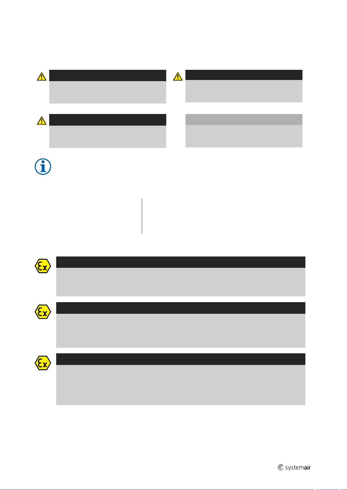
Danger
Direct hazard
Failure to comply with this warning will lead
directly to death or to serious injury.
Warning
Potential hazard
Failure to comply with this warning may lead to
death or serious injury.
Note:
Useful information and instructions
1.1.1 Instruction symbols
Instruction
♦ Carry out this action
♦ (if applicable, further actions)
Caution
Hazard with a low risk
Failure to comply with this warning may lead to
moderate injuries.
Important
Hazard with risk of damage to objects
Failure to comply with this warning will lead to
damage to objects.
Instruction with xed sequence
1. Carry out this action
2. Carry out this action
3. (if applicable, further actions)
2 Information on the explosion-protection devices
Danger
Explosion protection!
This warning marks information applying in use of the device in an explosion-capable area. Failure to
comply with these contents and instructions leads to loss of explosion protection and can lead to serious
injuries and death.
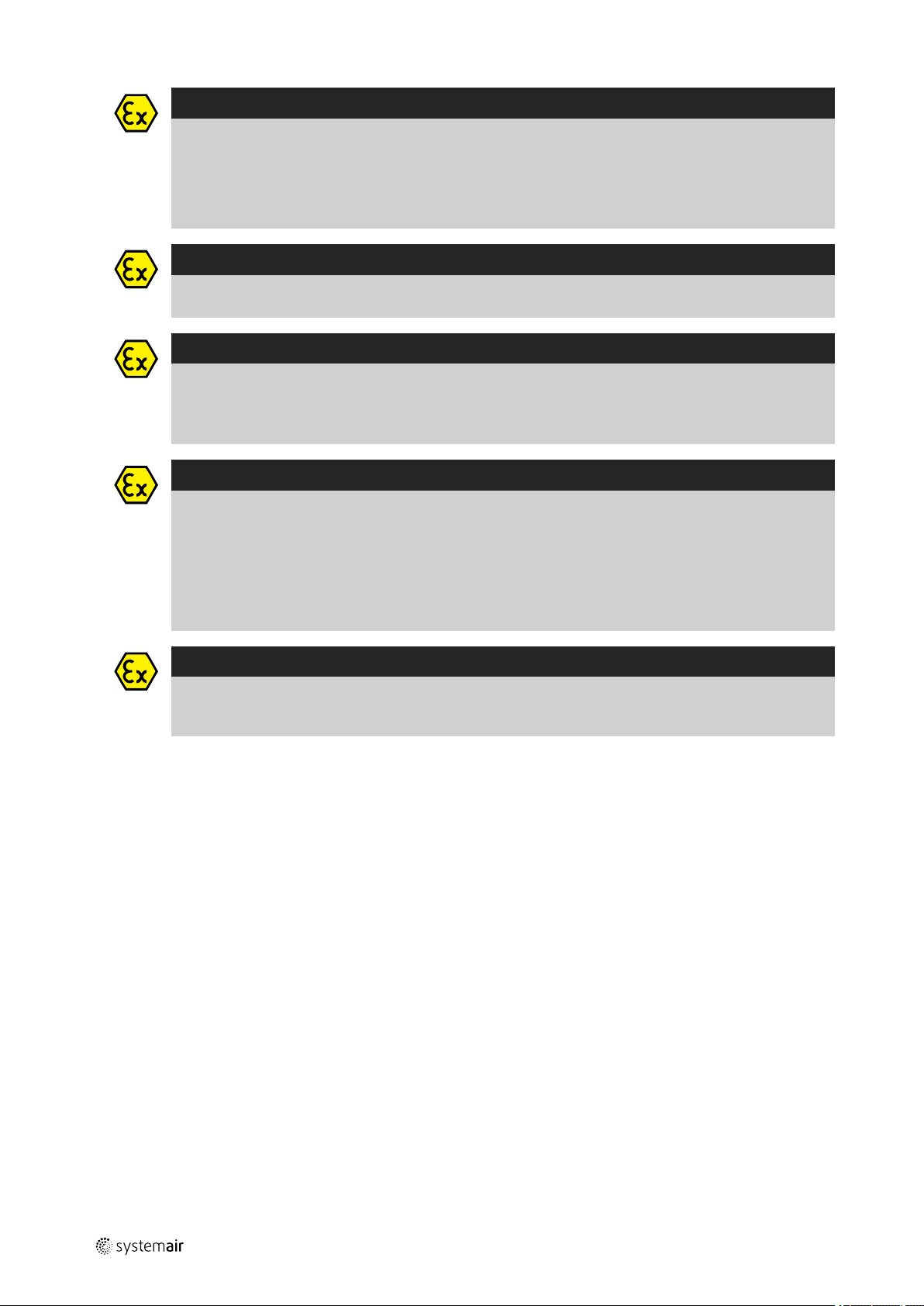
Warning
Hazard as a result of improper use of the fans.
These operating instructions and the name plate of the fan describe safe use of the EX fans.
♦ Read the operating instructions completely and carefully.
♦ When used in explosion-capable areas, examine the name plate. Only use type PRF-EX fans.
Warning
In order to rule out risks for the employees‘ health, protective clothing must be worn in explosioncapable
areas.
♦ Wear protective equipment during all work in the vicinity of the fan, details see 3.2 Personal protective
equipment, page 7.
♦ Pay attention to the information shown in the work area concerning personal protective equipment.
| 002
Page 6
| Important safety information
6
Warning
With a view to the choice of material, the EX fans fulfil the requirements of standard DIN 14986
(construction of fans for use in explosion-capable areas) as a result of specific protection measures in the
area of possible contact surfaces between rotating and stationary components (rotor/admission nozzle).
For the rotating part, a safety distance to the admission nozzle is guaranteed. The plant builder is
responsible for the selection of the materials for the fixed peripheral parts in fan constructions without
protective grids. Only pairs of materials according to standard DIN EN 14986 are to be used.
Warning
The statement of the temperature class on the EX name plate (motor) must match the temperature class of
the combustible gas which will possibly occur or the motor must have a higher temperature class.
Danger
Explosion protection
Transport damage or failure to comply with this information can lead to a loss of explosion protection.
♦ In the event of recognisable transport damage, do not put the device into operation and contact the
manufacturer.
Warning
The effects of lightning strikes must be limited to a hazard-free extent. Alongside protection against the
effects of „direct“ lightning strikes, this also includes protection against lightning strikes at a distance from
the building. The latter can lead to hazards as a result of excess voltages.
♦ Carry out a risk analysis according to DIN VDE 0100, part 443, containing a balance between protection
and consequences, taking the probability of the occurrence of excess voltages into account.
♦ Protect all devices, protective systems and components by suitable lightning and excess voltage
protection measures.
GB
Warning
Ignition protection class „d“
If fans are controlled with engines of the „d“ ignition protection class with frequency converter, thermal
protection by a PTC resistor in the motor is necessary.
3 Important safety information
Planners, plant builders and operators are responsible for the proper assembly and intended use.
♦ Read the operating instructions completely and carefully.
♦ Keep the operating instructions and other valid documents, such as the circuit diagram or motor instructions, with
the fan. They must always be available at the place of use.
♦ Observe and respect local conditions, regulations and laws.
♦ Only use the fan in a awless condition.
♦ Provide generally prescribed electrical and mechanical protective devices.
♦ During installation, electrical connection, commissioning, troubleshooting, and maintenance, secure the location and
premises against unauthorised access.
♦ Do not circumvent any safety components or put them out of action.
♦ Keep all the warning signs on the fan complete and in a legible condition.
♦ The device is not to be used by persons (including children) with reduced physical, sensory or mental capabilities, or
lack of experience and knowledge, unless they have been given supervision or instruction.
♦ Do not allow children to play with the device.
3.1 Personnel
The fan may only be used by qualified, instructed and trained personnel. The persons must know the relevant safety directives in order to recognise and to avoid risks. The individual activities and qualifications can be found in Table 1 Qual-
ifications, page 7.
| 002
Page 7
GB Warranty
Table 1 Qualifications
|
7
Activities
Storage, operation, transport, cleaning, disposal Trained personnel (see following note)
Electrical connection, commissioning, electrical
disconnection
Installation, disassembly Fitter or matching qualification
Maintenance
Repair
Qualifications
Electrical expert or matching qualification
Electrical expert or matching
qualification
Electrical expert or matching
qualification
Smoke extraction fans and EX fans only by agreement with
Systemair.
Fitter or matching
qualification
Fitter or matching
qualification
Note:
The operator is responsible for ensuring that personnel are instructed and have understood the contents of
the operating instructions. If something is unclear, please contact Systemair or its representative.
3.2 Personal protective equipment
Wear protective equipment during all work in the vicinity of the fan.
• protective working clothes
• protective working shoes
• protective working gloves
• helmet
• goggles
• hearing protection
3.3 5 rules of electrical safety
1. Disconnect (disconnection of
the electrical system from
live components at all
terminals)
2. Prevent reactivation
3. Test absence of voltage
4. Ground and short-circuit
5. Cover or restrict adjacent live parts
4 Warranty
For the assertion of warranty claims, the products must be correctly connected and operated, and used in accordance
with the data sheets. Further prerequisites are a completed maintenance plan with no gaps and a commissioning report. Systemair will require these in the case of a warranty claim. The commissioning report is a component of this
document. The maintenance plan must be created by the operator, see section 13.3 Maintenance, page 20.
5 Delivery, transport, storage
5.1 Safety information
Warning: Risk from rotating fan blades
♦ Prevent access by unauthorised persons by safety personnel or access protection.
Warning: Suspended loads
♦ Wear protective equipment during all work in the vicinity of the fan, details see 3.2 Personal protective equipment,
page 7.
♦ Do not walk under suspended loads.
♦ Make sure that there is nobody under a suspended load.
5.2 Delivery
Each fan leaves our plant in an electrically and mechanically proper condition. We recommend transporting the fan to
the installation site in the original packaging.
| 002
Page 8

| Delivery, transport, storage
8
Checking delivery
♦ Check the packaging and the fan for transport damage. Any findings should be noted on the cargo manifest.
♦ Check completeness of the delivery.
Unpacking
Warning
When opening the transport packaging, there is a risk of damage from sharp edges, nails, staples,
splinters etc.
♦ Unpack the fan carefully.
♦ Check the fan for obvious transport damage.
♦ Only remove the packaging shortly before assembly.
♦ Wear protective equipment during all work in the vicinity of the fan, details see 3.2 Personal protective
equipment, page 7.
5.3 Transport
5.3.1 Safety information
Warning: Electrical or mechanical hazards due to fire, moisture, short circuit or malfunction.
♦ Never transport the fan by the connecting wire, terminal box, impeller, protection grille, inlet cone or silencer.
♦ In open transport, please make sure that no water can penetrate into the motor or other sensitive parts.
♦ We recommend transporting the fan to the installation site in the original packaging.
GB
Caution: If transported without care during loading and unloading, the fan may be damaged.
♦ Load and unload the fan carefully.
♦ Use hoisting equipment that is suitable for the weight to be hoisted.
♦ Observe the transportation arrows on the packaging.
♦ Use the fan packaging exclusively as transport protection and not as a lifting aid.
5.4 Storage
♦ Store the fan in the original packaging in a dry, dust-free location protected against weather.
♦ Avoid the effects of extreme heat or cold.
Important
Hazard due to loss of function of the motor bearing
♦ Avoid storing for too long (recommendation: max. 1 year).
♦ Check that the motor bearing functions properly before installation.
| 002
Page 9
GB Description
6 Description
• Material of the housing: UV resistant PE (PRF-EX from PP)
• Material of the impeller: PP
Warning
• Examined according to ATEX directive 2014/34/EU
• Antistatic housing
The explosion-protected fans can be used for temperature classes T1 to T4 and have been registered for
conveying explosion-capable atmosphere in Zone 1 and 2, category 2G and 3G, with the groups IIA, IIB and
IIC (only PRF-EX Ex d).
PRF-EX Ex d possess an IEC norm motor in an Ex d finish which can be controlled via a frequency inverter
and has an added-on terminal box in Ex e finish. Motor protection by integrated PTC resistor with connection
to a motor protection switching device e.g. U-EK230E.
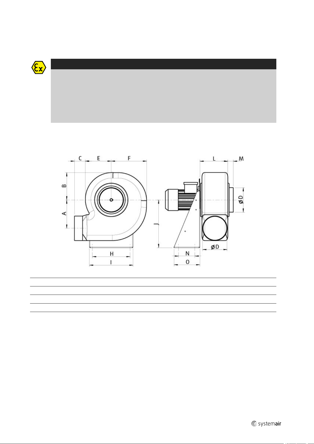
6.1 Dimension
Table 2 Dimensions
|
9
[mm]
PRF, PRF EX 125 142 165 60 125 150 183 200 235 250 115 40 100 140
PRF, PRF EX 160 182 210 80 160 190 237 255 290 310 150 40 100 140
PRF, PRF EX 180 205 230 80 180 205 275 277 320 350 160 40 120 190
PRF, PRF EX 200
PRF, PRF EX 250
A B C
227 245 80 200 220 313 320 355 410 170 40 150 230
284 330 80 250 270 380 330 370 495 195 40 170 250
ØD
E F H I J L M N O
6.2 Fan and motor data
• Max. temperature of transported air, max. ambient temperature, sound pressure –> see data sheet, available in our
online catalogue.
• Voltage, current, enclosure class, weight –> see name plate
• The motor data can be found on the name plate of the motor, or in the technical documents of the motor
manufacturer.
6.3 Chemical components
The standard variants of the plastic used are polyethylene (PE) and polypropylene (PP). As a matter of principle, the rotor material is the indicator for the selection.
| 002
Page 10

Description GB
|
10
Note:
The list “COMPATIBILITY WITH CHEMICAL AGENTS” is available in our online catalogue. This list has been
produced to the best of our knowledge, all statements without guarantee for correctness. Examination of
the media to be transported is a matter for the plant operator. Here, it is merely a question of a
recommendation.
6.4 Minumum air gap
The following table shows the minimum air gap between the rotor and the housing.
Size
125 2.00 180 3.0 250 4.5
160 2.50 200 3.5
minimum air gap [mm]
Size
minimum air gap [mm]
Size
minimum air gap [mm]
6.5 Intended use
Indended use PRF and PRF EX
• The fans are intended for installation in ventilation systems.
• The fans are exclusively intended for extract air applications.
• The fans have been developed and built to convey air with the simultaneous presence of corrosive gases/vapours.
Indended use PRF EX
• The EX fans are not ready-for-use products, but have been designed as components for ventilation equipment, machines and systems. They may only be operated when they have been installed in accordance with their use and
safety has been ensured by protective devices pursuant to DIN EN 294 (DIN EN ISO 12100-1).
• The fans are only intended for conveying air or explosion-capable atmospheres of Zone 1, Category 2G, and Zone 2,
Category 3G.
• The maximum permissible operating data on the name plate apply for an air density of 1.2 kg/m³ (sea level) and a
max. air humidity of 80%.
6.6 Incorrect use
Incorrect use refers mainly to using the fan in another way to that described. The following examples are incorrect
and hazardous:
Incorrect use PRF and PRF EX
• Conveying of abrasive, combustible air or air with
solid particles.
• Conveying media which attack the materials of the
fan (housing, rotor and slip rings of polypropylene).
• Operation without duct system or protection grille
• Operation with the air connections closed
Incorrect use PRF
• Conveying of explosive and combustible media
Incorrect use PRF EX
• The fans are not suited to intake of media containing
dust or with a such a dust content that depositing on
the blades and on the housing of the fan may
influence the operation and the explosion protection
of the fan. If there is the risk of such deposits,
matching waste air cleaning must be carried out.
| 002
Page 11

GB
Fan type: PRF-EX 125D2 EX d
U (V) / F (Hz)
:
Date
:
:
isol. class
:
F
P2 (kW)
:
Enclo. class
:
IP 55
n (1/min)
:
m (kg):20
PA-No.
:
I (A)
19.01.2017400Y / 50
1,16
0,25
3000
II 2G c IIC T4
Systemair GmbH
Seehöfer Strasse 45
97944 Boxberg
GERMANY
TPS 17 ATEX 85751 004 X
1
1
2
2
3
3
5
4
6
4
4
a
b
c
7
8
9
10
11
10
7 Name plate and type key
Name plate and type key |
11
1
2
Type designation
Voltage/current/
frequency
3 Power
4(a/b/c)
Enclosure class/fan
impeller speed/weight
Article number/
5
production number/
manufacturing date
6
7
8
9
10
11
Certifications
Certification office/ATEX
registration number
Identification
Manufacturer Address
Insulation class
Production number
Table 3 Type key PRF
PRF 200 DV
-
EX d
Ignition protection class
Pressure-proof encapsulation
- Not classified (< 0.75KW or PRF EX)
IE2
IE3
International efficiency class 2
International efficiency class 3
Motor type
D2
D4
DV
E4
2poled/controllable by frequency converter/3 phased
4 poled/controllable by frequency converter/3 phased
4 poled/voltage controllable/3 phased
4 poled/controllable by frequency converter/1 phased
Flange diameter
Fan type
PRF
Plastic Fans — Industrial fans for “Aggressive Gases/Vapours”
| 002
Page 12

| Name plate and type key
12
7.1 Ex key (example)
GB
0123
CE sign
0123
II
2G
c
Ex d
Ex e
IIC Group
T4
Gb EPL Equipment Protection Level
TPS 17 ATEX
85751 004 X
Notified office (quality assurance system)
Device certified for Ex area
Device group (here: use above ground)
Device category and classification (G = gas; D = dust)
Ignition protection class (constructive safety)
Ignition protection class (pressure-proof encapsulation)
Ignition protection class (increased safety)
Temperature class
ATEX registration number
II 2G c Ex de IIC T4 Gb / TPS 17 ATEX 85751 004 X
| 002
Page 13

GB
7.2 Marking
Name plate and type key |
13
Designation
Device group II
Device
category/
classification
Ignition
protection class
mechanical
Ignition
protection class
electrical
Group
Classification
„2G“
„3G“
“c”
„d“
„e“ Increased
II
2
3
G
Constructive
safety
Pressureproof
encapsulation d
safety, Ex e
IIA Propane
IIB
IIC
Marking
All areas with explosion-capable atmosphere
apart from mining, underground and above
ground in cases of mien damp.
Category 2 / Zone 1 / high safety / Devices of
this category are intended for use in areas in
which occasional occurrence of an explosioncapable atmosphere of gases, vapours, mists is
to be expected. Increased safety, Ex e.
Category 3 / Zone 2 / normal safety / Devices of
this category are intended for use in areas in
which occurrence of an explosion-capable
atmosphere of gases, vapours, mists is not to be
expected, but if it does occur then in all
probability only rarely and for a short period of
time.
Gases / Vapours / Mists
EN 13463-5
Motor: Pressure-proof encapsulation
Terminal box: Occurrence of sparks, light arc or
inadmissible temperatures which could act as
sources of ignition is prevented by additional
measures and an increased degree of safety.
Ethylene
Hydrogen
Temperature
class
T1 450 °C
T2 300 °C
T3 200 °C
T4 135 °C
I: Methane
IIA: Acetone, ammoniac, methane, methanol,
propane, toluene
IIB: Town gas
IIC: Hydrogen
IIA: Ethyl alcohol, n-butane
IIB: Ethylene
IIC: Acetylene
IIA: Otto fuels, diesel fuels, heating oils
IIB: Hydrogen sulphide
IIA: Acetaldehyde, ethyl ether
| 002
Page 14

Accessories GB
1
2
3
4
6
5
7
3
|
14
8 Accessories
Note:
For details of the accessories, please check our online catalog or contact Systemair.
Table 4 Accessories
PRF, PRF EX
1
2 VP
3 ASS-P
4 VKS-P
Fan
Splinter protection
Flexible connection
Gravity shutter
5 VKA-P
6 WSD
7 SD
Adjust. damper
Weather roof KIT
Vibration damper
9 Installation
9.1 Safety information
Warning: Danger from falling fan or fan parts.
♦ Check the surface before installation for load bearing capacity.
♦ Consider all static and dynamic loads when selecting hoisting equipment and fastening components.
General safety information
♦ Fans installed in areas where personnel access regularly must be equipped with a splinter guard, please contact
Systemair.
♦ Installation may only be carried out by adequately qualified persons, details see Table 1 Qualifications, page 7.
♦ Wear protective equipment during all work in the vicinity of the fan, details see 3.2 Personal protective equipment,
page 7.
♦ Abide by the system-related conditions and requirements of the system manufacturer or plant constructor.
♦ Do not dismantle or circumvent safety elements, or put them out of function.
♦ Move the rotor of the fan by hand before you install it in order to check that it moves freely.
♦ Provide contact and intake protection and ensure safety distances according to DIN EN ISO13857 and DIN 24167-1.
♦ Prevent the possibility of foreign bodies being drawn in.
♦ To reduce transmission of vibration to the duct system, we recommend flexible connections from our accessory
range, see chapter Accessories.
♦ The materials the fan is made of have to be compatibel to the transported media.
♦ Pay attention to the safety data sheet of the chemical substances transported with the fan.
| 002
Page 15

GB
Ø D
min.
2,5x Ø D
min.
2,5x Ø D
9.2 Preconditions
Installation |
15
♦ Ensure that the fan and all its components are
undamaged.
♦ Ensure that there is enough space to install the fan.
♦ Protect against dust and moisture when installing.
Danger
Hazard of explosion of an ignition-capable atmosphere!
♦ Seal the system carefully.
♦ Install accessory parts correctly.
♦ The housing must be protected from impact by shock, if necessary using splinter protection (accessory)!
Aluminothermic Reaction - At high air speeds, in combination with aluminium, rust particles may lead to an
aluminothermic reaction which, in the worst case, can trigger the ignition of an explosive atmosphere.
Upstream or downstream components, or those which lie directly in the air flow, must not have any
unprotected aluminium or steel surfaces. Surface protection is required which at least fulfils the cross-cut
test classification 2 / DIN EN ISO 2409, in order to prevent an aluminothermic reaction. Steel with an
electro-galvanised or hot-dip galvanised surface is not critical. However, care must be taken that
appropriate protection is also applied to the cut edges.
Important
Damage to the bearings or other parts of the fan can occur.
♦ Do not place a duct bend directly before or after the fan!
♦ Ensure a smooth and constant air flow to the device. Ensure a free exhaust. See Fig. 1 Straight ducts,
page 15.
♦ Ensure that the information on the name plates (fan
and motor) matches up with the operating conditions.
♦ Fit the fans in such a way that there is sufficient
access for troubleshooting, maintenance and repair.
♦ If harmful or hazardous products are transported,
check the general condition of the fan before opening.
• Rectangular duct system: D = Hydraulic diameter • Round duct system: D = Nominal diameter
Fig. 1 Straight ducts
9.3 Installation variations
The installation is possible in any mounting position.
9.4 Lightning protection device
♦ If the risk assessment shows that there is the risk of an atmospheric discharge, lightning protection measures must
be taken. For reasons of operational safety, provide for a suitable lightning protection system according to country
specific directives (e.g. DIN VDE 0185).
| 002
Page 16

| Electrical connection
16
10 Electrical connection
10.1 Safety information
Danger
Hazard of explosion of an ignition-capable gas/air atmosphere!
If the wire ends which have not been connected are fitted to the external current circuits within the
explosion-capable area,
♦ a connection box selected to match this area with its own certification and explosion-protection
identification must be used.
♦ the electrical data, information on temperature monitoring and on admissible operation with part voltage,
if applicable, can be seen from the data sheet in question.
Protection against explosions in general:
♦ Always ensure potential compensation.
♦ Earth at the planned earthing point.
Warning: Danger from electrical voltage!
♦ Observe the 5 rules of electrical safety, see 3.3 5 rules of electrical safety, page 7.
♦ Prevent the ingress of water into the connection box.
♦ Electrical connection may only be carried out by adequately qualified persons, details see Table 1 Qualifications, page
7.
♦ Observe and respect local conditions, regulations and laws.
♦ Wear protective equipment during all work in the vicinity of the fan, details see 3.2 Personal protective equipment,
page 7.
GB
Warning: Danger due to electrostatic influence on medical implants (e.g. cardiac pacemaker)!
♦ Persons with medical implants (e.g. cardiac pacemaker) should keep enough distance to the fan.
10.2 Preconditions
♦ Abide by the system-related conditions and requirements of the system manufacturer or plant constructor.
♦ Safety elements may not be dismantled, circumvented or deactivated.
♦ Install a circuit breaker in the permanent electrical installation, with a contact opening of at least 3 mm at each pole.
♦ Potentially, the fans may become charged with static electricity. If this represents a risk, please contact Systemair.
10.3 Connection
♦ Check if the data on the nameplate matches the
connection data.
♦ Complete the electrical connection according to the
circuit diagram.
♦ Lay the connection cables in the terminal box in such
a way that allows the cover of the terminal box to be
closed without resistance.
♦ Use all of the locking screws.
♦ Insert the screws by hand to avoid damaging the
thread.
♦ Tighten all glands well in order to guarantee
protection class IP.
♦ Screw the lid of the terminal box/inspection switch
evenly tight.
♦ Connect the cable end in a dry environment.
10.4 Protective grounding wire
The protective grounding must have a cross-section equal to or greater than that of the phase conductor.
10.5 Residual current circuit breaker
All-current-sensitive residual current circuit breakers are required for use in alternating-current systems with 50/60 Hz,
in combination with electronic devices such as EC motors, frequency converters or uninterruptible power supplies
(UPS).
| 002
Page 17

GB Commissioning
10.6 Protecting the motor
Important
Damage to motor due to overcurrent, overload or short circiut.
♦ Lead-out temperature monitors must be integrated in the control circuit in such a way that, if a fault
occurs, the motor cannot switch on again automatically after it has cooled down.
♦ Motor lines and temperature monitor lines should be laid separately on principle.
♦ Without thermal protection: Use a motor protection switch!
10.7 Variable-speed fans
Warning
Resonant frequencies may result in increased vibration in certain speed ranges. These vibrations may
destroy components.
♦ Only operate the fan outside these speed ranges.
♦ Skip over these speed ranges.
♦ Pass through these speed ranges so quickly that any vibration cannot exceed the admissible resonant
frequency values.
♦ Observe the operating instructions of the frequency converter.
|
17
Caution
Damage as a result of incorrect commissioning of the frequency converter.
♦ Install the fan and frequency converter as near as possible to one another.
♦ Use shielded cables.
♦ All components (fan, frequency converter and motor) must be grounded.
♦ We recommend using all-pole sinus filters.
♦ Avoid running the fan via the frequency converter below 10 Hz.
♦ Heating of the motor due to use of a variable frequency drive must be checked in the application by the
customer.
♦ Never exceed the maximum impeller rotation speed indicated on the name plate of the fan.
11 Commissioning
The system operator is responsible for the correct operation of the fan and/or the system!
Warranty claims can only be made if commissioning work is carried out correctly and written evidence thereof is
provided.
It is recommended to fill out the commissioning report 17 Commissioning Report, page 23.
11.1 Safety information
♦ Commissioning may only be carried out by adequately qualified persons, details see Table 1 Qualifications, page 7.
♦ Wear protective equipment during all work in the vicinity of the fan, details see 3.2 Personal protective equipment,
page 7.
♦ Pay attention to the safety data sheet of the chemical substances transported with the fan.
| 002
Warning
♦ Comply with fundamental information in the commissioning of the EX fan:
• DGVU 113-001 (explosion protection rules (EX-RL))
• TRGS 727 (Avoiding ignition hazards due to electrostatic charges).
Page 18

Operation GB
|
18
11.2 Preconditions
♦ Installation and electrical connection have been
correctly performed.
♦ Residual material from installation and foreign objects
have been removed from the fan and ducts.
♦ Inlet and outlet are free.
♦ Safety devices have been fitted.
♦ Ground cable is connected.
♦ Cable glands are tight.
♦ Nominal current (from the name plate) is not
exceeded.
♦ Data on the name plate corresponds with the
connection data.
♦ For EX fans, check whether the minimum air gap
between the rotor and the housing matches the value
stated in 6.4 Minumum air gap, page 10
11.3 Tests
♦ Before switching the fan on, check for externally visible damage and ensure that the protective equipment functions
properly.
1. Switch the fan on.
2. Checks:
♦ Direction of rotation/conveyance. The direction of rotation always applies looking at the impeller.
• The direction of rotation is best observed just before the fan stops.
♦ Smooth running (any vibrations and noise)
♦ Current consumption
♦ Compare the current consumption with the nominal consumption on the name plate.
♦ Tightness of all connections
3. Switch the fan off.
12 Operation
12.1 Safety information
Danger
Hazard of explosion of an ignition-capable gas/air atmosphere!
When commissioning the EX fan, the fundamental information from DGVU 113-001 (explosion protection
rules (EX-RL)) and TRGS 727 (Avoiding ignition hazards due to electrostatic charges) must be known.
Warning: Hazard from electrical voltage or moving components.
♦ The device may only be operated by adequately qualified persons, details see Table 1 Qualifications, page 7.
♦ Abide by the system-related conditions and requirements of the system manufacturer or plant constructor.
Warning: Risk by careless use of aggressive media.
Careless use of aggressive media can lead to very severe injuries.
♦ Pay attention to the safety data sheet of the chemical substances transported with the fan.
12.2 Preconditions
♦ Ensure access only to persons who can safely handle
the device.
♦ Only use the fan in accordance with the operating
instructions and the operating instructions for the
motor.
♦ Do not dismantle or circumvent safety elements, or
put them out of function.
♦ The EX fans have been admitted for S1 continuous
operation.
| 002
Page 19

GB
Troubleshooting/maintenance/repair |
13 Troubleshooting/maintenance/repair
13.1 Safety information
♦ Troubleshooting/maintenance/repair may only be carried out by adequately qualified persons, details see Table 1
Qualifications, page 7.
♦ Wear protective equipment during all work in the vicinity of the fan, details see 3.2 Personal protective equipment,
page 7.
♦ Observe the 5 rules of electrical safety, see 3.3 5 rules of electrical safety, page 7.
♦ Abide by the system-related conditions and requirements of the system manufacturer or plant constructor.
♦ The impeller must be at a standstill.
♦ Pay attention to the safety data sheet of the chemical substances transported with the fan.
Danger
Loss of explosion protection
• The manufacturer must always be consulted before any maintenance or repair work is carried out!
Repairs should preferably always be carried out by the manufacturer! Exceptions can be made for nonrelevant components such as terminal boxes, screwed cable connections, etc. These can also be dealt
with on-site by the operator's qualified staff (authorised personnel). Non-compliance will result in the
ATEX certification being revoked!
• For ATEX-certified products, the repair or replacement of fan components is expressly only permitted
after consultation with the manufacturer and only if the manufacturer's original parts are used!
19
13.2 Troubleshooting
Table 5 Troubleshooting
Problem Possible causes
Impeller imbalance
Soiling on the impeller Clean carefully, rebalance
Material decomposition on the
impeller due to aggressive
Fan does not run
smoothly
Air output of fan too
low
Grinding sounds
when starting or
operating the fan
material conveyed.
Impeller rotates in wrong
direction.
Deformation of impeller due to
excessive temperature.
Vibrations, oscillations
Impeller rotates in wrong
direction.
Wrong wiring configuration (e.g.
Y instead of Delta).
Pressure losses too high. Optimize the line routing.
Flow regulators not or only
partly open.
Intake or pressure ducts are
blocked.
Check if the duct connections of
the fan are strained.
Remedy
Rebalancing by a specialist company if possible,
otherwise contact Systemair.
Contact Systemair
Change direction of rotation if possible, otherwise contact
Systemair.
Ensure that the temperature does not exceed the certified
value/Install new impeller.
Check the installation of the fan/check the duct system,
see 9 Installation, page 14.
Change direction of rotation if possible, otherwise contact
Systemair.
Check and possibly correct the wiring configuration.
Check opening position on site.
Remove the blockage.
Loosen the duct connections and realign it.
| 002
Page 20

| Troubleshooting/maintenance/repair
20
Troubleshooting cont'd
GB
Thermal contacts/
resistors have
triggered
Fan does not reach
nominal speed
Motor does not
rotate
Electronics/motor
overheated
Impeller rotates in wrong
direction.
Missing phase
Motor overheated
Motor blocked
Defective motor winding
Improperly aligned drive motor
Control units (if used) such as
frequency converter or
transformer are set incorrectly.
Mechanical blockage Remove the blockage.
Frozen condensate blocking the
impeller
Faulty supply voltage Check the supply voltage, re-establish the voltage supply.
Faulty connection
Temperature monitor has
responded.
Insufficient cooling Improve cooling.
Overloaded motor
Ambient temperature too high Check if the correct fan is used for your application.
Change direction of rotation if possible, otherwise contact
Systemair.
In case of a 3 phase standard motor (not EC), check if all 3
phase are present.
Check the cooling impeller (if used), measure the motor
winding (if possible) / contact Systemair.
Contact Systemair
Contact Systemair
Contact Systemair
Correct the settings of the control units.
Thaw and drain the condensate
Disconnect from the power supply, correct the
connection, see circuit diagram.
Allow the motor to cool down, find and resolve the cause
of the fault.
Check if the correct fan is used for your application.
Note:
For all other damage/defects, please contact Systemair. Defective safety-relevant fans (for Ex and smoke
extraction applications) must be replaced completely.
13.3 Maintenance
Warranty claims can only be made if maintenance work is carried out correctly and written evidence thereof is
provided.
We recommend regular maintenance intervals to ensure continuous fan operation. These maintenance intervals are
specified in the “Activities” table below. In addition, the operator must carry out follow-up activities such as cleaning,
replacing defective components or other corrective measures. For traceability reasons, a maintenance plan must be
created which documents the work carried out. This must be created by the operator. If the operating conditions are
"extreme", the maintenance intervals must be reduced so that maintenance is carried out more frequently. Examples
of extreme operating conditions:
• Ambient temperature > 35 ºC or < 5 ºC, or temperature fluctuations > 20 K
• Use in an explosion capable area
Table 6 Activities
Extreme operating
conditions
Every six
months
Activity
Check the fan and its components for visible damage,
corrosion and contamination.
Check the impeller for damage and imbalance.
Clean the fan/ventilation system (see 14 Cleaning, page
21).
Normal operating
conditions
Every six
months
X X
Annually Quarterly
X X
X X
| 002
Page 21

GB
1
2
3
4
5
6
Activities cont'd
Cleaning |
21
Check the screwed connections for damages/defects and
check that they are firmly seated.
Check the fan intake is free from contamination.
Check that the fan and its components are being used
correctly.
Check the current consumption and compare this with the
rated data.
Check the vibration dampers (if used) are working
correctly and check for visible damage and corrosion.
Check the electrical and mechanical protective equipment
is working correctly.
Check the fan’s rating plate is legible.
Check the connection clamps and screwed cable
connections for damage/defects, and check that they are
firmly seated.
Check the flexible connectors for damage.
Note:
For all other damage/defects, please contact Systemair.
X
X X
X
X X
X
X
X X
X
X
See normal operating
conditions
See normal operating
conditions
See normal operating
conditions
See normal operating
conditions
See normal operating
conditions
See normal operating
conditions
13.4 Spare parts
♦ Use original spare parts from Systemair only.
♦ When ordering spare parts, please specify the serial number of the fan. This can be found on the name plate.
1 Motor
2
Flange plate
3
Motor disc
4
Impeller
5
Taper bush
6 Housing
14 Cleaning
14.1 Safety information
♦ Cleaning may only be carried out by adequately qualified persons, details see Table 1 Qualifications, page 7.
♦ Wear protective equipment during all work in the vicinity of the fan, details see 3.2 Personal protective equipment,
page 7.
♦ Observe the 5 rules of electrical safety, see 3.3 5 rules of electrical safety, page 7.
♦ The impeller must be at a standstill.
♦ Pay attention to the safety data sheet of the chemical substances transported with the fan.
| 002
Page 22

| Deinstallation/dismantling
22
14.2 Procedure
Important
Keeping the fan clean extends its service life.
♦ Drain condensation off
♦ Only use compressed air if the fan is used for conveying air in the presence of gases/vapours without
hovering particles.
♦ If the fan is used in an environment with vapours of specific chemical substances, get information from
the chemical safety data sheet with a view to the recommended cleaning products.
♦ Install a filter monitor.
♦ Do not use steel brushes or sharp-edged objects.
♦ Do not use a high-pressure cleaner (steam jet cleaner) under any circumstances.
♦ Do not bend the fan blades when cleaning.
♦ When cleaning the impeller, pay attention to balance weights that have been positioned
♦ Keep the airways of the fan clear and clean them if necessary with a brush.
15 Deinstallation/dismantling
♦ Pay attention to the safety data sheet of the chemical substances transported with the fan.
Deinstall and dismantle the fan in reverse order of installation and electrical connection.
GB
16 Disposal
♦ Ensure material is recycled. Observe national regulations.
♦ The device and the transport packaging are predominantly made from recyclable raw materials.
♦ Disassemble the fan into its components.
♦ Separate the parts according to:
• reusable material
• material groups to be disposed of (metal, plastics, electrical parts, etc.)
| 002
Page 23

GB Commissioning Report
17 Commissioning Report
Warranty claims can only be made if commissioning work is carried out correctly and written evidence thereof is
provided.
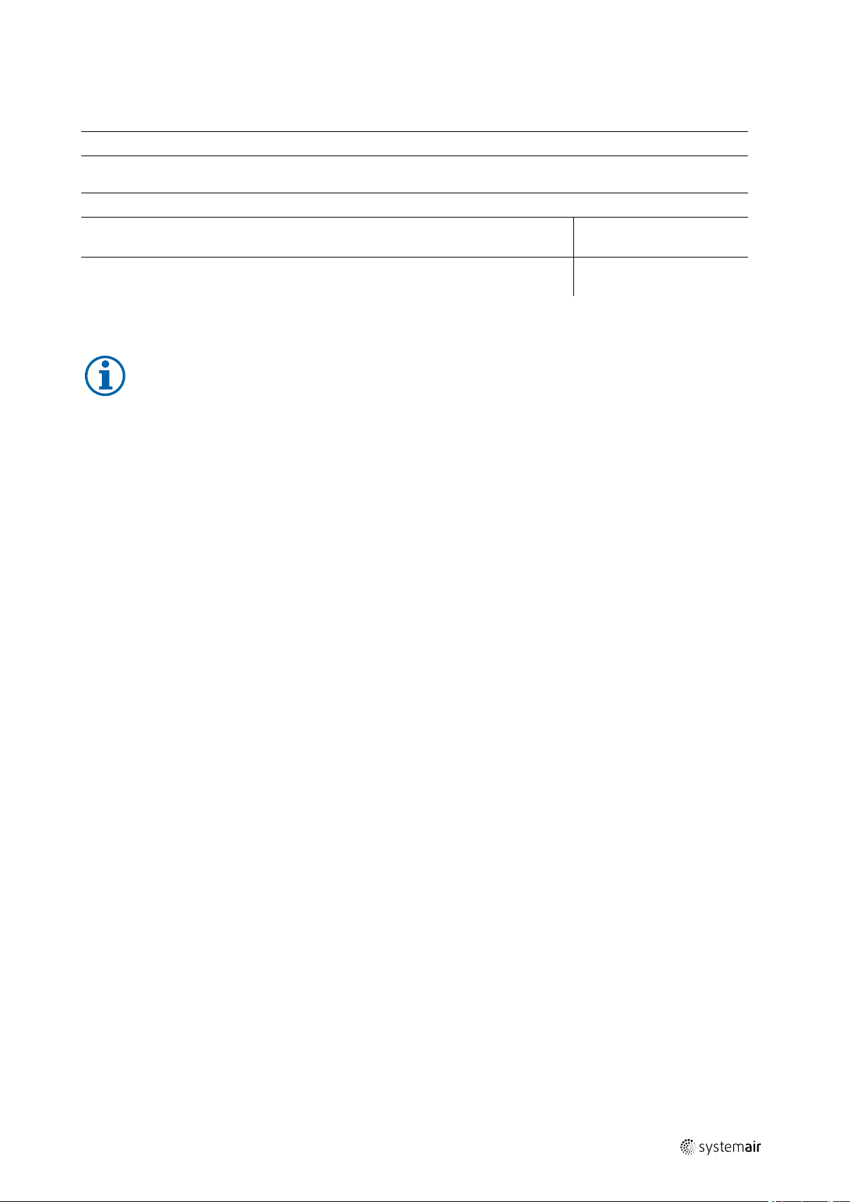
Fan
Description:
Article no.: Manufacturing order no.:
Installer
Company: Contact person:
Company address:
Tel. no.: Email:
Operator (Place of installation)
Company: Contact person:
Company address:
Tel. no.: Email:
|
23
Type of connection
Directly to mains
0-10 V signal (EC motor)
via contactor control
Transformer
Frequency converter
Sinus filter
Shielded cables
Motor protection
Motor protection switch or motor protection relay
PTC resistor
Resistance value [Ω]:
Thermal contact
Electrical motor protection
Others:
Functional check
Impeller easily rotatable (by hand)
Rotation direction acc. to directional arrow
Yes No
□ □
□ □
□ □
□ □
□ □
□ □
□ □
Yes No
□ □
□ □
□ □
□ □
Yes No
□ □
□ □
Nominal data - Fan (name plate on fan housing)
Voltage [V]: Current [A]:
Frequency [Hz]: Power [kW]:
Fan impeller speed [rpm]:
Measured data at commissioning
Voltage [V]: Temp. of transported air [°C]:
Current L1 [A]*:
| 002
Fan impeller speed [rpm]:
Page 24

| EU Declaration of conformity
24
Current L2 [A]: Air volume [m3/s]:
Current L3 [A]:
*For single-phase fans, fill in line “Current L1 [A]” *Δ- Pressure between suction-side and discharge of the fan
Differential pressure [Pa]*:
If an air flow measurement is not possible, this value can be calculated using the following formula:
=
Air volume [m³/s]:
Duct cross-section [m²]
X
Flow speed [m/s]
Grille measurement acc. to VDI 2044
Commissioning of the fan successful?
Date, installer's signature
Date, operator's signature
GB
Yes No
□ □
18 EU Declaration of conformity
The manufacturer: Systemair GmbH
Seehöfer Straße 45
97944 Boxberg
Germany
Product designation:
Type designation:
Since year of manufacture:
The manufacturer declares that the above mentioned products in their design and construction and the version
marketed by us complies with the harmonization legislation listed below:
EU directives: 2006/42/EC Machinery directive
The EU Declaration of conformity of the PRF-EX fan is also attached to the delivery as a separate document.
PRF
PRF, PRF EC
2018
2014/30/EU Directive electromagnetic compatibility (EMC)
2011/65/EU RoHS directive
| 002
Page 25

| 002
Page 26

www.systemair.com
Plastic Fans — Industrial fans for “Aggressive Gases/Vapours” · · 2019-01-10 · 002
 Loading...