

Page 1

Air Distribution Products
OPTIMA-RES-A
Residential VAV System Box
Data Sheet
Variable Air Volume Controllers | 1 / 22
Page 2

Table of Contents
Description .......................................1
Design ..........................................1
Controls .........................................2
Factory Settings ................................2
Basic Functional Characteristics ...................2
Basic Parameters and Features ....................2
Master/Slave Conguration .......................2
Dimensions ......................................4
Ordering Code ....................................4
Accessories .......................................5
RC-C3DOC .....................................5
MZ3-Touch ....................................5
EC-Basic – CO2 + Temperature Room Controller ......6
CO2RT ........................................6
ZTH-EU .......................................6
Technical Parameters ..............................7
Solutions for Room Controls
with VAV Ventilation Systems ........................10
MZ3-Touch ...................................11
Ventilation Control Panel .........................11
EC-Basic – CO
RC-C3DOC .....................................15
+ Temperature Room Controller .......13
2
Installation, Maintenance & Operation .................22
Transport & Storage ................................22
Supplement ......................................22
Related Products ..................................23
Good to
know
Current information on all
products is available at
design.systemair.com
Page 3

Variable Air Volume Controllers | 1 / 24
Description
OPTIMA-RES-A is a compact system of supply
and extract VAV controllers intended for ventilation
control of residential premises. The basic functionality
is continuous supply and extract air ow volume control
in master/slave operation mode. Additionally, it can be
switched into override operation modes like open
or close damper, or minimum or maximum air ow
volume control.
Highlights
• Complete VAV supply and extract master/slave solution
• AC 230 V power supply
• Electrical safety elements and connection terminals
on board
• Noise attenuators included
• Fit for installation on surface or into gypsum walls
or ceilings
• VAV controllers can be easily detached and mounted
in other supply/extract conguration
Design
The system of OPTIMA-RES-A system is encased
in a galvanised steel box. The system consists of:
• One supply and one extract variable OPTIMA-R air ow
controller in a circular galvanised steel body
• Electric part with power supply and control circuitry
• Acoustic attenuation
The VAV controllers are mounted to the circular duct
connections by sleeves, so the VAV controllers are easily
removable. The system box is equipped with cable pass
diaphragms for cables related to power supply, setpoint
control signal, feed-back signal and override signal.
These cables shall be connected by a service person
on site. The corresponding terminals are available
according to the wiring diagram.
List of Accessories
Detailed information about accessories
for OPTIMA-RES-A is available
• RC-C3DOC: Room Controller
• MZ3-Touch: Ventilation Control Panel
• EC-Basic – CO2 + Temperature Room Controller
• CO2RT: CO
• ZTH-EU: Service Tool for VAV Controllers
Room Transmitter
2
on page 5.
Page 4
2 / 24 | Variable Air Volume Controllers
Controls
The residential VAV system is equipped with BLC4 type compact controllers in the master/slave connection.
The controllers use analog input for the setpoint signal and analog output for the feedback signal. The type of the
signals is DC 0 V ... 10 V. The VAV controllers are factory calibrated as standard to the air volume indicated in the table
below or, upon request, they can be adjusted to site required settings of the V
also be readjusted on site with the ZTH-EU
hand held service tool. If specic air volumes for V
required, they must be indicated in the ordering code or noted in the order for adequate calibration in the factory.
Factory Settings
min
/V
range. The air volumes can
max
and V
min
max
would be
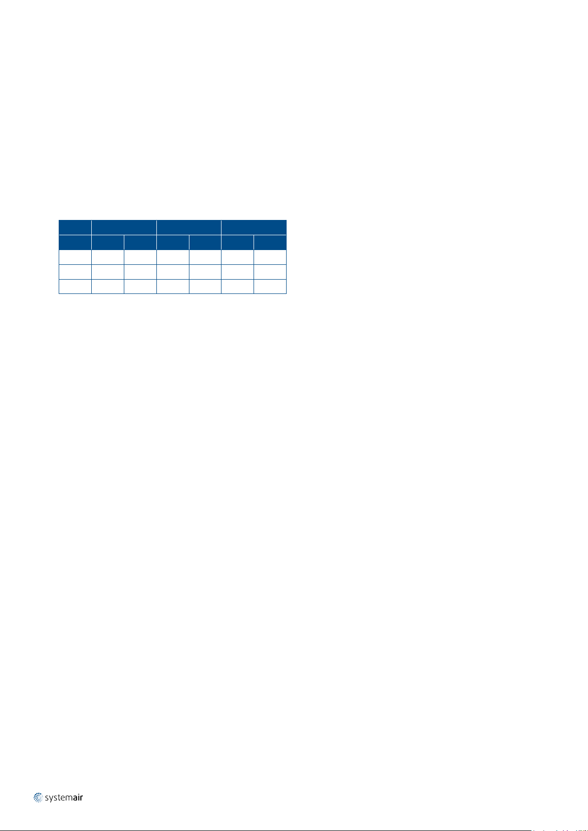
Size V
(mm) (m
100 57 16 254 71 311 86
125 88 24 398 111 486 135
160 145 40 651 181 796 221
@ 2 m/s V
min
3
/h) (l /s) (m3/h) (l /s) (m3/h) (l /s)
@ 9 m/s V
max
@ 11 m/s
nom
Basic Functional Characteristics
Controller type: OPTIMA-RES-A-…BLC4
Basic Parameters and Features
Flow volume adjustment setpoint signal:
Analog input DC 0 V … 10 V. The Systemair MZ3-Touch room control device is primarily foreseen to be connected
to the analog input. It can operate in automatic mode, continuously controlling the air ow volume dependent from
temperature, VOC or CO
four discrete steps between the preset V
Other control devices with 0 V ... 10 V control output can also be used, e.g. Systemair RC-C3DOC.
Controller parameters setup tools: Belimo ZTH-EU
concentration. If switched to manual mode, the air ow setpoint can be adjusted manually in
2
min
and V
of OPTIMA-RES-A.
max
Feedback signal (actual air ow volume): Analog output DC 0 V … 10 V
Power supply (each VAV controller, secured by transformer on board):
AC 24 V/50 Hz DC 24 V
4 VA 2 W
Power supply (whole system): AC 230 V/50 Hz
Protection class (closed system box): IP40
Master/Slave Conguration
The VAV system is congured as master/slave. The supply air VAV controller (the master) reads the ow volume
setpoint from an external source like e.g. a room controller or manual setpoint dial. The control range (V
the master VAV controller can be adjusted at the factory or on site with the ZTH-EU conguration tool. The feedback
signal from master VAV represents the actual measured air ow volume. This signal is connected to the extract air
VAV controller (the slave) as the setpoint for the air ow volume. So the air ow volumes of supply and extract air are
always equal with high reliability.
min
, V
max
) of
Page 5
Variable Air Volume Controllers | 3 / 24
Master (Supply Air) VAV Controller Setup
V
adjustable between 0 and V
min
V
adjustable between V
max
min
nom
and V
. Lowest possible adjustment is 20% of V
nom
nom
.
Slave (Extract Air) VAV Controller Setup
V
adjusted to 0, shall not be changed.
min
V
adjusted equal V
max
, shall not be changed.
nom
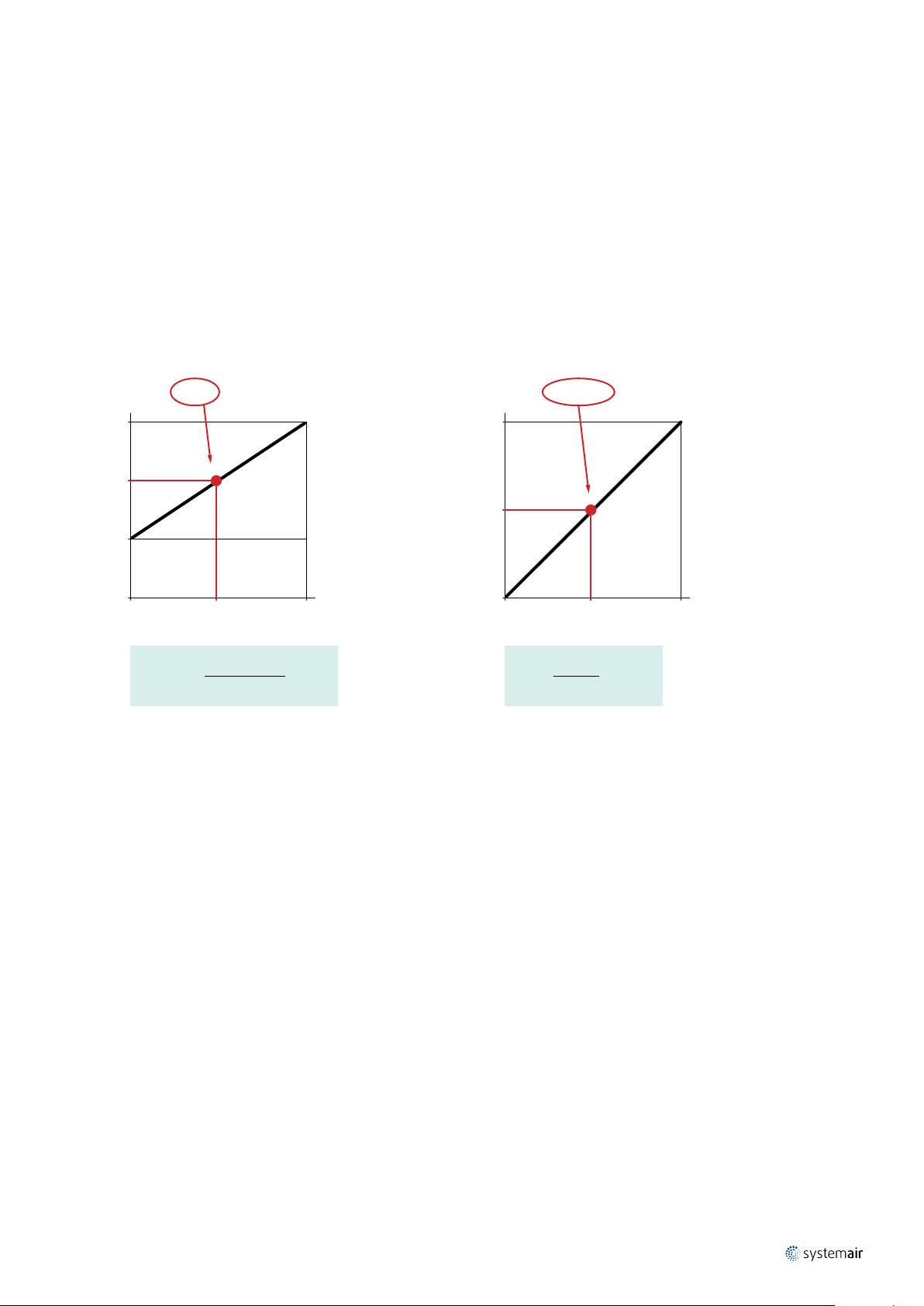
Setpoint/Feedback Signal and Air Flow Volume Calculation for VAV Controller
Setpoint, UC : 0 V ... 10 V
V
max
/h)
3
q (m
V
min
0 10
UC (V) =
: Air ow volume setpoint signal value (range DC 0 V … 10 V)
U
c
UC (V)
V
q - V
- V
max
min
· 10
min
q: Air ow volume
Feedback, U: 0 V ... 10 V
10
U (V)
0 V
q (m3/h)
U (V)
q =
10
· V
nom
nom
: Minimum adjusted air ow volume (lower limit of control range)
V
min
: Maximum adjusted air ow volume (upper limit of control range)
V
max
U: Measured air ow volume feedback signal value (range DC 0 … 10 V)
: Nominal air ow volume calibrated in factory – not adjustable.
V
nom
Page 6
4 / 24 | Variable Air Volume Controllers
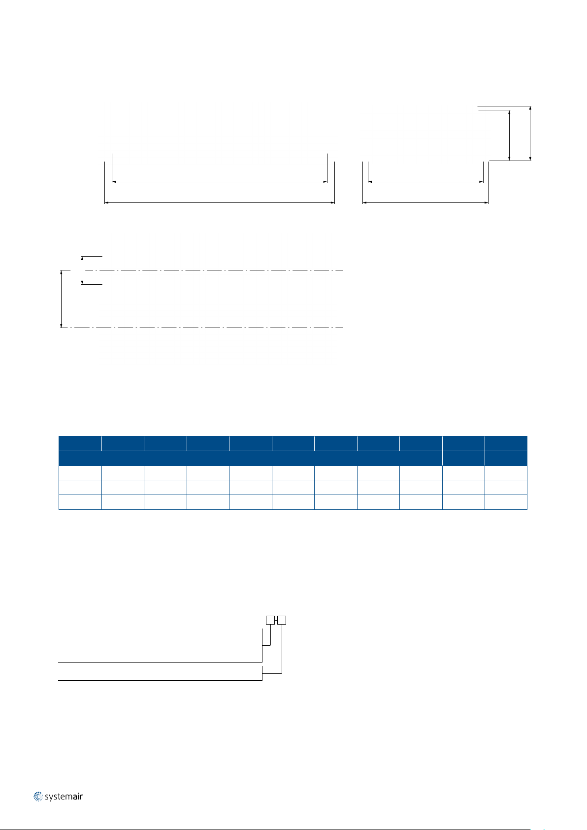
Dimensions
1
H
H
W
W
1
L
L
1
øD
K
Fig. 1: Dimensions of the OPTIMA-RES-A
Tab. 1: Dimensions of the OPTIMA-RES-A
DN øD K W W
(mm) (kg) (l)
100 98 250 495 555 200 225 1080 1170 25 147
125 123 280 550 610 235 260 1180 1270 29 202
160 157,5 320 640 700 282 306 1190 1280 35 275
1
H H
1
L L
1
m v
Ordering Code
OPTIMA-RES-A-
100
Nominal size
Control range setup
ø (mm)
V
... V
min
max
(m3/h)
Example of the Ordering Code
OPTIMA-RES-A-125-130-310
Residential VAV control system of size 125, control range 130 m³/h (V
125
160
) up to 310 m³/h (V
min
max
)
Page 7

Accessories
RC-C3DOC
Room Controller
Art. No.: 27142
Variable Air Volume Controllers | 5 / 24
Complete pre-programmed room controller intended to control heating, cooling, CO
in a zone control system.
and other physical parameters
2
MZ3-Touch
Ventilation Control Panel
Art. No.: 92690
• Positioner and controller for comfort ventilation with a touch panel.
• Design according to Feller EDIZIOdue®.
• Manual operation with 4 steps.
• AUTO operation: The controller activates the ventilation based on controls curve.
• Automatic reset of the party air level.
• One DC 0 V … 10 V controls output to control the ventilation system. One DC 0 V … 10 V input to
measure CO
or other sensors.
2
Page 8

6 / 24 | Variable Air Volume Controllers
EC-Basic – CO2 + Temperature Room Controller
Art.No. 24808
• For simultaneous control of the room temperature and the CO
of the value with the higher control difference.
• Pre-adjustable heating or cooling control loop.
• One DC 0 V ... 10 V VAV control output.
concentration (on-board sensors) based on priority
2
CO2RT
Room Transmitter
CO
2
Art. No.: 13704, 14357
Room sensor for measuring carbon dioxide concentration in indoor environments.
ZTH-EU
Service Tool for VAV Controllers
Art. No.: 27655
Conguration and setup tool for VAV controllers.
Page 9

Technical Parameters
Discharged Sound Power Level
Legend
Variable Air Volume Controllers | 7 / 24
p
s
q
V
L
WA
L
W
Pa Pressure drop
m3/h
l/s
Air ow volume
dB(A) A-weighted total discharged sound power level
dB Non-weighted total discharged sound power level
OPTIMA-RES-A-100
Air Flow p
3
/h Pa dB dB(A) 63 Hz 125 Hz 250 Hz 500 Hz 1 kHz 2 kHz 4 kHz 8 kHz
m
s
L
WA
L
W
Non-Weighted Sound Power Level
100 28 42 34 41 20 19 20 9 -8 2
250 32 42 33 41 26 27 28 18 5 15
500 37 43 33 41 30 33 35 26 15 25
750 41 45 33 41 33 36 38 30 21 30
@ 2 m/s *
min
57
V
1000 43 46 33 41 35 39 41 33 25 34
100 28 34 15 32 19 23 25 18 <5 10
250 37 40 18 36 28 33 36 27 13 21
500 45 47 20 39 34 40 43 34 21 30
750 49 51 21 41 38 44 48 38 26 35
155
1000 52 54 22 42 41 48 51 41 29 39
100 31 34 12 30 19 26 29 23 9 19
250 42 44 18 38 30 37 40 32 18 28
500 50 52 23 44 38 46 48 39 25 35
750 55 56 26 48 43 51 53 43 29 39
@ 9 m/s *
max
254
V
1000 58 60 28 50 47 54 56 46 32 42
NOTE:
* Standard factory air volume setting, if not indicated differently upon order.
can be adjusted from 0 m3/h to V
The V
min
can be adjusted from 20% to 100% of the V
The V
max
value from from the table above.
max
value from the table above.
max
Page 10

8 / 24 | Variable Air Volume Controllers
OPTIMA-RES-A-125
Air Flow p
3
/h Pa dB dB(A) 63 Hz 125 Hz 250 Hz 500 Hz 1 kHz 2 kHz 4 kHz 8 kHz
m
s
L
WA
100 27 42 34 41 20 21 19 9 -7 2
250 32 43 36 42 26 29 27 19 5 15
500 37 45 38 43 31 35 33 26 14 25
750 41 47 39 43 34 38 37 31 20 31
@ 2 m/s *
min
88
V
1000 43 48 40 44 36 41 39 34 24 35
100 26 36 18 35 20 22 23 14 <5 <5
250 36 41 20 38 29 33 34 25 11 19
500 44 47 22 40 36 41 42 34 20 29
750 49 51 22 42 40 46 47 39 26 35
243
1000 53 54 23 43 43 49 50 43 29 39
100 30 38 20 37 23 25 28 18 5 13
250 41 46 24 43 33 37 39 29 16 24
500 49 53 27 48 41 47 47 38 24 32
750 55 57 29 50 46 52 52 43 28 37
@ 9 m/s *
max
398
V
1000 58 60 30 52 49 56 56 46 32 41
L
W
Non-Weighted Sound Power Level
OPTIMA-RES-A-160
Air Flow p
3
/h Pa dB dB(A) 63 Hz 125 Hz 250 Hz 500 Hz 1 kHz 2 kHz 4 kHz 8 kHz
m
s
L
WA
L
W
Non-Weighted Sound Power Level
100 31 47 40 46 24 25 22 11 -5 4
250 37 49 39 48 31 33 32 23 8 18
500 43 51 39 50 37 39 40 33 18 29
750 47 53 39 51 40 43 44 38 24 35
@ 2 m/s *
min
145
V
1000 50 55 38 52 42 46 48 42 28 39
100 30 38 25 36 22 25 27 18 <5 10
250 40 44 26 42 31 36 37 29 15 23
500 47 51 27 46 39 43 45 38 23 32
750 52 54 27 49 43 48 50 42 28 38
398
1000 55 57 28 51 46 51 53 46 32 42
100 35 40 26 38 24 29 33 24 11 19
250 44 49 29 47 35 39 42 33 20 29
500 51 56 33 53 43 47 49 41 27 36
750 55 60 35 57 47 52 53 45 31 40
@ 9 m/s *
max
651
V
1000 58 63 36 60 51 55 56 48 34 44
Page 11
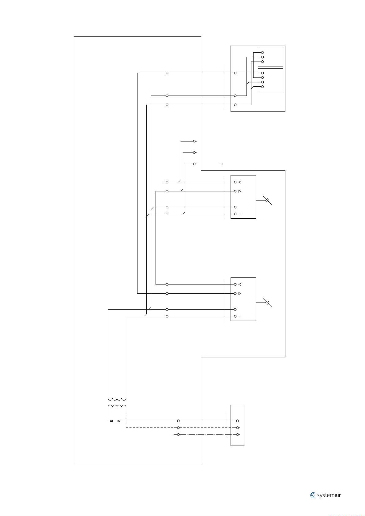
Variable Air Volume Controllers | 9 / 24
0...10V
0V AO
24V AI 24V
0V AO
-CO2/VOC
-MZ3
0...10V
-RC-a
Flow control
FC
5
G
G
G0
0V
200 V
2x2x0,8
J-Y(St)Y
-WS-RC-a
extract
5
3
Feedback / MP-BUS
supply
Feedback / MP-BUS
4XEH:1
3
4
w
U5
2002-474
2002-479/011-000
2002-479/011-000
2002-479/011-000
XEH:1 2 3
3
2 4 XRC:1 2 3
XSU:1
2
˜
1 2 4
1
-
500 V
5x0,75
YSLCY
WS-VAV-EHa
5
w
3
U5
2
˜
1
-
500 V
5x0,75
YSLCY
/3
WS-SUa
24V AC
VAV-EHa
M M
24V AC
VAV-SUa
-T1
2 4
+VAV-VERa
1 3
230V/24V, 30VA
F1
T1A
230V
2002-433
L1
NX:PE
500 V
3x1,5
CYKY-J
-WL-VAVa
LN
PE
Via Topology
-RC_VAVa
Page 12

10 / 24 | Variable Air Volume Controllers
Solutions for Room Controls with VAV Ventilation Systems
The variable air ow controlled ventilation as a part of demand oriented control of room climate can be integrated
in different ways according to various user requirements. The basic part of the climate control is the various room
controllers. Each of them ts a different control solution at a corresponding cost level.
Room Control Solutions, Quick Overview
Room Controller
Parameters, Functions
Number of control loops 3 1 2
Value assigment to control loop Freely adjustable Fixed Fixed
Control loop sequence Freely adjustable - Fixed (simultaneous)
Analog outputs (control setpoints) Heating valve, Cooling valve, VAV VAV VAV
Internal sensors (analog values) 1 × Temperature -
External sensor analog inputs 1 × Pt1000, 1 × DC 0 V ... 10 V 1 × DC 0 V ... 10 V -
Binary inputs 2 (congurable) - -
Controlled values for VAV
Measurement range of controlled
values
VAV control normal operation
0(2) V ... 10 V = V
VAV control manual override
modes available
Bus communication protocols/
Physical media
... V
min
max
RC-C3DOC MZ3-Touch
Temp. Heat/Temp. Cool, CO
Humidity, Others
Adjustable for CO
Yes Yes Yes
Open/Close/V
Modbus RTU, BACNet MSTP/RS485 - -
, Fixed for others
2
min /Vmax
, VOC,
2
(by BMS)
, VOC Temp. Cool, CO
CO
2
Fixed Fixed
, 40%, 60%, 100%
V
min
(120 min) of V
max
EC-Basic – CO2
+ Temperature Room Controller
1 × Temperature, 1 × CO
2
-
2
Page 13

Variable Air Volume Controllers | 11 / 24
MZ3-Touch
Ventilation Control Panel
For VAV air ow control based on a single physical value like CO2 or VOC concentration.
Functions
The room controller can set the air ow volume on the VAV controller by the 0 V ... 10 V signal. The leading value
for the control is the concentration of CO
transmitter shall be used with with a 0 V ... 10 V measurement signal. For CO
This signal shall be connected to the analog input of the room controller. No setpoint or control parameter
adjustments are possible. The operation modes can be adjusted on the room controller by touching the key
on the cover plate.
, eventually VOC in the air. For the measurement of this value, a separate
2
, it corresponds to 0 ppm ... 2000 ppm.
2
In automatic mode, the CO
2
the air ow setpoint for VAV.
V
max
max
80%
= 10 V ⇒ V
C
U
60%
40%
min
V
min
= 0 V ⇒ V
C
U
0 400
0 ppm ⇒ UC = 0 V 2000 ppm ⇒ U
800 1200 1600 2000
CO2 (ppm)
concentration inuences
= 10 V
C
In manual mode, the chosen ow volume level
inuences the air ow set-point for VAV. The “party”
position (V
) is temporary. After 120 minutes, the
max
system changes the position to “Maximum” (60%).
V
max
max
80%
= 10 V ⇒ V
C
U
60%
40%
min
V
min
= 0 V ⇒ V
C
U
0 Minimum
Normal Maximum Party
Page 14

12 / 24 | Variable Air Volume Controllers
Topology
OPTIMA...
VAV Controller
0 V ... 10 V
MZ3-Touch
Ventilation Control Panel
0 V ... 10 V
CO2RT
CO
Room Transmitter
2
Page 15
Variable Air Volume Controllers | 13 / 24
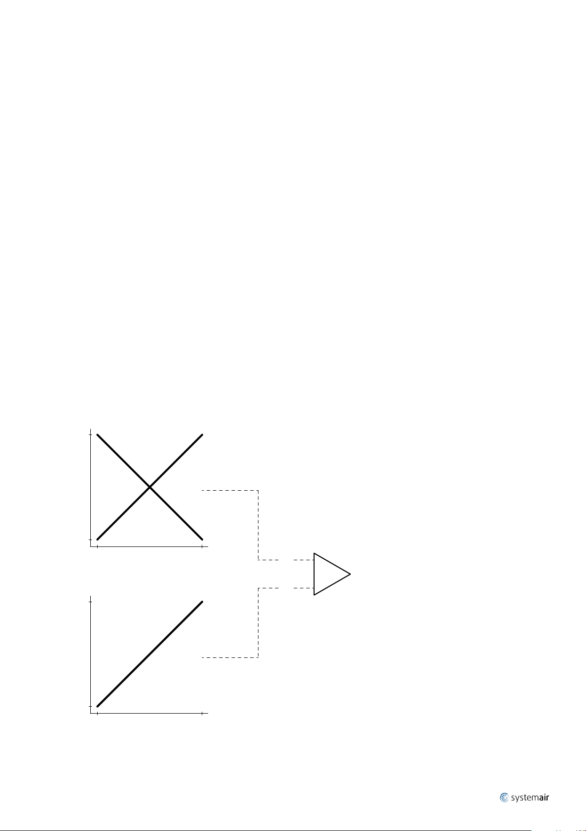
EC-Basic – CO2 + Temperature Room Controller
For VAV air ow control based on two physical values, temperature and CO2 concentration simultaneously.
Functions
The room controller can set the air ow volume on the VAV controller by the 0 V ... 10 V signal. The leading values for
the control are the temperature (cooling mode or heating mode) and the concentration of CO
are measured inside the room controller, no additional transmitters shall be connected. The temperature and the CO
level are measured and evaluated simultaneously. The one with the currently larger control difference is chosen as
the actual control value for the VAV setpoint. The CO
control has no set-point or range to adjust. The temperature
2
setpoint can be adjusted manually by a dial on the room controller. The cooling or the heating mode can be preadjusted by jumper switches.
in the air. Both values
2
2
RC temperature control
control
RC CO
100
100
2
Heating
demand value (%)
Min Max
Room temperature Tr (°C)
demand value (%)
Min Max
Room air CO2 value Q (ppm)
Cooling
Comparator,
max. value selection
Y1
Y = Max (Y1, Y2) VAV flow demand value
Y2
Page 16
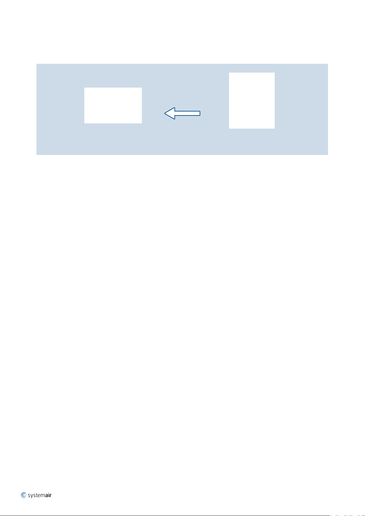
14 / 24 | Variable Air Volume Controllers
Topology
0 V ... 10 V
OPTIMA...
VAV Controller
EC-Basic
CO
+ Temperature Room Controller
2
Page 17

Variable Air Volume Controllers | 15 / 24
RC-C3DOC
Room Controller
For VAV air ow control based on multiple physical values and control states in different congurable operation modes
and sequences.
Functions
The room controller has the following main control functions:
• Heating control, separate controls of the heating valve and VAV in heating mode
• Cooling control, separate controls of the cooling valve and VAV in cooling mode
• CO
(or VOC, or humidity or other values) control by VAV
2
• Dew point surveillance protection
• Frost protection
• Different operation modes switched according to room occupation state
• Energy conservation procedures in case of room control conditions disturbance (e.g. open window)
The following measurement and detection capabilities are included or can be connected to the RC:
• Room temperature measurement on board
• External temperature measurement connectable via analog input
• External CO
(or other value) measurement connectable via analog input
2
• External change-over switch connectable via digital input
• External dew point detection connectable via digital input
• External presence/occupation detection connectable via digital input
• External window opening detection connectable via digital input
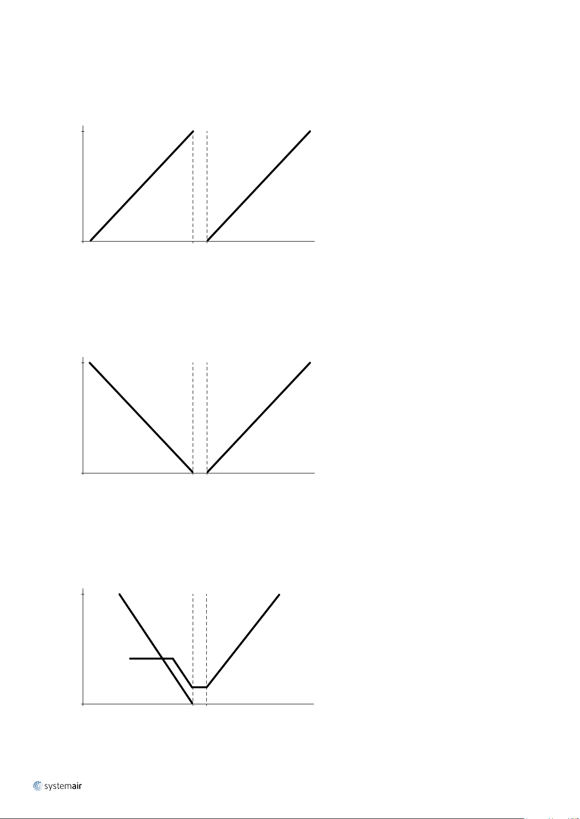
Page 18
16 / 24 | Variable Air Volume Controllers
The following control loop sequences can be congured on the RC:
• Heating/Heating
100%
Output signal
0%
• Heating/Cooling
100%
Neutral zone
Heating 1 Heating 2
48% 52%
Heating demand
Neutral zone
100%
Output signal
0%
Heating Cooling
SP SP
Room temperature Tr (°C)
• Heating/Cooling with VAV-control
100%
Output signal
0%
Heating output Cooling output
Max air flow
on heating
demand
(settable)
Heating Cooling
Neutral zone
SP SP
Room temperature Tr (°C)
100%
Increasing air flow on heating demand
Basic air flow (settable)
100%
Page 19

• Cooling/Cooling
Variable Air Volume Controllers | 17 / 24
100%
Output signal
0%
Cooling 1 Cooling 2
• Heating/Cooling/VAV
100%
Neutral zone
48% 52%
Cooling demand
Neutral zone Neutral zone
Y1 Y2 Y3
100%
Output signal
20% by default min. flow
at cool output for VAV control
0%
100% ... 0% 0% ... 48%
Controller output
52% ... 100%
Page 20

18 / 24 | Variable Air Volume Controllers
• Heating/Cooling/VAV simultaneaously with CO2 control
Value with higher control difference becomes control value.
100%
Output signal
20% by default min. flow
at cool output for VAV control
0%
100%
Neutral zone Neutral zone
Y1 Y2 Y3
100% ... 0% 0% ... 48%
Controller output
(Y3 cooling demand, CO
Y3 cooling demand
CO2 reduction demand
Y3
52% ... 100%
Comparator, maximum
reduction demand)
2
Y3 output - VAV damper
20% by default min. flow
at cool output for VAV control
• Heating/VAV/Cooling
(reversed sequence)
reduction
demand
2
CO
0%
100%
Output signal
600 ppm by default
level to start
CO
2
open damper
CO2 level
Y1 Y3 Y2
800 ppm by default
level when damper
CO
2
fully open
Neutral zone Neutral zone
20% by default min. flow
at cool output for VAV control
0%
100% ... 0% 0% ... 48%
Controller output
52% ... 100%
Page 21

• Heating/Cooling with forced ventilation
Variable Air Volume Controllers | 19 / 24
100%
Y1
Neutral zone
Output signal
20% by default min. flow
at cool output for VAV control
0%
100% ... 0% 0% ... 48%
• Heating/Cooling or Heating/Heating via change-over
Summer mode activated by change-over input
Neutral zone
100%
Y1 Y2
Y3 = 100% at forced ventilation
Y2
Neutral zone
52% ... 100%
Controller output
Output signal
0%
22°C by default heating setpoint 24°C by default cooling setpoint
Room temperature Tr (°C)
Winter mode activated by change-over input
Neutral zone
100%
Output signal
0%
Y1
52% ... 100% 0% ... 48%
Room temperature Tr (°C)
Y2
22°C by default heating setpoint
Page 22

20 / 24 | Variable Air Volume Controllers
• Full range change-over determined heating/cooling control by VAV combined with CO2 control
100
Heating
demand value (%)
RC temperature control
Min Max
Room temperature Tr (°C)
100
control
2
Cooling
Comparator,
max. value selection
Y1
Y = Max (Y1, Y2) VAV flow demand value
Y2
RC CO
demand value (%)
Min Max
Room air CO2 value Q (ppm)
Page 23

Variable Air Volume Controllers | 21 / 24
Adjustment and indication of parameters
The operation parameters, procedures and limits can be adjusted with the help of pushbuttons and indicated
by the LCD display on the room controller.
Adjustment and indication are also possible via PC with corresponding hardware and software.
Communication
The room controller has an RS485 on-board communication serial port for which the Modbus RTU or BACNet MS/TP
bus communication protocols can be turned on.
Topology
BMS
OPTIMA...
VAV Controller
IR24-PC
Presence detector
0/1 potential-free 0/1 potential-free
0 V ... 10 V
0/1 potential-free
Modbus RTU
or BACNet MS/TP
Bus communication
Room Controller
RC-C3DOC
Heating valve
0 V ... 10 V
0 V ... 10 V
0 V ... 10 V/Pt1000
Cooling valve
CO2RT
CO
Room transmitter
2
y
Window contact
Humidistat/Thermostat/Timer switch, etc.
Page 24

22 / 24 | Variable Air Volume Controllers
Installation, Maintenance & Operation
Information about installation, maintenance and operation is available in the document “UserManual_OPTIMA-RES-A”.
OPTIMA-RES-A is mounted on the wall or ceiling and is connected to a spiro duct by a rubber gasket tight connection.
The system box can be xed to the wall or ceiling by screws through the holes in four mounting ears on the bottom
plate. The electrical connection terminals and VAV controllers can be found under the cover of the system box. The
cover can be removed by turning the two locks on the cover plate with a screw driver by 90°. To avoid falling out
after unlock the cover plate is tight to the system box by chains. The cover plate in the closed position is sunken into
the frame. This enables to attach a plaster board to the outer surface of the cover. So the inspection opening cover
can be from the same material and ush with the surrounding wall or ceiling where the system box is installed. The
plaster board for the cover must be foreseen with cut-outs to keep the cover locks accessible.
The power supply and signal cables can be pulled into the box through the diaphragm between the supply/extract
air connections. The cables must be xed inside the box on the xing ridge by cable straps. This avoids excessive
mechanical stress on the cables. The cables shall be connected to the spring terminals according to the wiring
diagram. To protect the circuitry from overload or short circuit fault, there is a fuse terminal on the power supply.
Dry indoor conditions with an operation temperature range of -20°C to +70°C.
Transport & Storage
Dry indoor conditions with a temperature range of -40°C to +50°C.
Supplement
Any deviations from the technical specications contained herein as well as the terms should be discussed
with the manufacturer. We reserve the right to make any changes to the product without prior notice,
provided that these changes do not affect the quality of the product and the required parameters.
Current information on all products is available at
design.systemair.com
Page 25

Related Products
OPTIMA-R
VAV Controller
Air ow volume control units for standard air ow velocity range.
Product information is available within the
and on
Systemair DESIGN.
“DataSheet_OPTIMA-R” technical documentation
Variable Air Volume Controllers | 23 / 24
OPTIMA-LV-R
Low Velocity VAV Controller
Air ow volume control units for low to medium air ow velocity range.
Product information is available within the
and on
Systemair DESIGN.
“DataSheet_OPTIMA-LV-R” technical documentation
Page 26

www.systemair.com
Systemair Production s.s. · October 2019 · DataSheet_OPTIMA-RES-A_EN_201910
 Loading...