

SystemAir MRH 450, MRH 400, MRH Series, MRH 500, MRH 630 Installation And Operating Instructions Manual
...Page 1
MRH
English Originalversion
Installation and Operating Instructions for
Page 2
Previous issues: IMO_MRH_en_17_02_2017
Changes:
App. 4: wiring and explanation changed
Föregående version: -
Ранее инструкция: -
The data stated in these operating instructions are merely for the purpose of describing the product. Information
about a certain property or suitability for a certain purpose of use cannot be derived from our information. The information does not release the user from his own assessments and examinations.
Please consider the fact that our products are subject to a natural wear and ageing process.
All rights are with Systemair, also for the event of applications for protective rights.
Any powers of use, such as copying and forwarding rights, are with us.
An exemplary configuration has been shown on the title page. The product supplied can therefore deviate from the
illustration. The original operating instructions have been written in English language.
Page 3
Contents
1 General information ................................... 4
1.1 List of information ........................................ 4
1.1.1 Specific safety symbols ................................. 4
1.1.2 List of instructions for action ........................ 5
1.2 Notes on the documentation ........................ 5
2 Important safety information ..................... 5
2.1 Safety notes .................................................. 5
2.2 Personnel ...................................................... 5
2.2.1 Mounting personnel ..................................... 5
2.2.2 Work on the electrical equipment ................ 6
2.2.3 Personnel for operation, use,
maintenance and cleaning ............................ 6
2.3 Intended use ................................................. 6
2.4 Improper use ................................................ 6
3 Warranty .................................................... 6
4 Transport, storage ...................................... 7
4.1 Transport ...................................................... 7
4.2 Storage .......................................................... 7
5 Description ................................................. 8
5.1 Technical data ............................................... 8
5.2 Dimensions ................................................... 8
8.2 Commissioning ............................................ 11
9 Operation ................................................. 12
9.1 Operation/use generally ............................. 12
9.2 Emergency use (use in case of fire) ............. 12
9.3 Dual use of hatch + fan (daily powered
ventilation + emergency use) ...................... 13
9.4 Dual use of hatch + fan (daily natural
ventilation + emergency use) ...................... 13
10 Maintenance/troubleshooting ................. 14
10.1 Malfunctions and troubleshooting
(generally) ................................................... 15
10.2 Cleaning ....................................................... 15
10.3 Maintenance, service .................................. 15
10.4 Spare parts .................................................. 16
11 Uninstalling/dismounting ......................... 17
12 Disposal .................................................... 17
12.1 Disposal of the fan ...................................... 17
12.2 Disposal of packaging .................................. 17
Appendix 1: Dimensions ...................................... 18
Appendix 2: Installation examples ...................... 19
6 Installation ................................................. 8
6.1 Safety information ........................................ 8
6.2 Preconditions for installation........................ 8
6.3 Installation .................................................... 8
7 Electrical connection .................................. 9
7.1 Residual current circuit breaker ................. 10
7.2 Connection of thermal protection .............. 10
8 Commissioning ......................................... 10
8.1 Preconditions .............................................. 10
Appendix 3: Wiring diagram, connection ............ 21
Appendix 4: Connection of actuator .................... 22
Appendix 5: Mechanical hazards, safety
warnings ............................................................. 23
Appendix 6: EC-Declaration of Conformity .......... 24
MRH 06.04.2017 3
Page 4
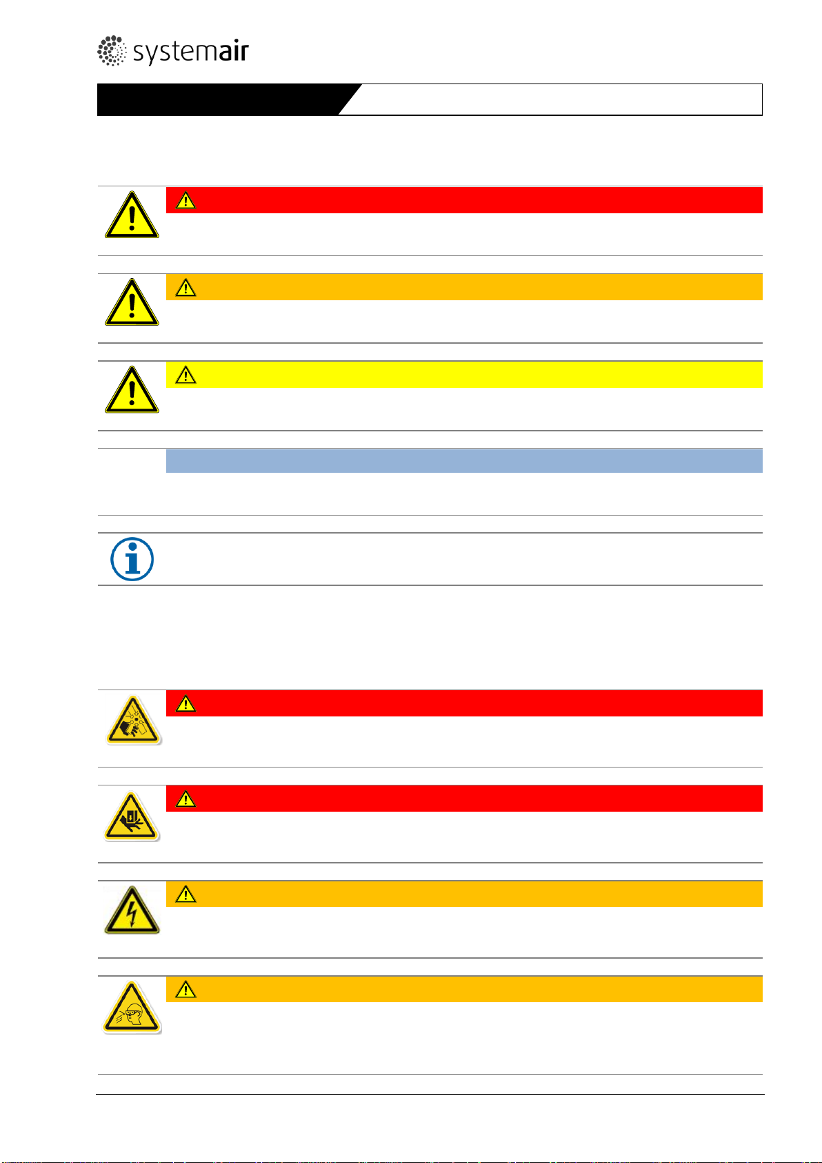
DANGER
Direct danger
Failure to comply with this warning leads directly to death or to serious bodily harm.
WARNING
Possible danger
Failure to comply with this warning potentially leads to death or to serious bodily harm.
CAUTION
Hazard with a low risk
Failure to comply with this warning potentially leads to moderate injuries.
ATTENTION
Hazard with risk of property damage
Failure to comply with this warning leads to property damage.
NOTE
Useful information and notes
DANGER
Hazard from touching impeller, if not covered with protective grid!
This warning identifies situations with a danger for life from touching impeller. Failure to comply with this
warning leads to the risk of death or serious injuries.
DANGER
Hazard from crushing/shearing from closing hatch cover!
This warning identifies situations with a danger for life from closing the hatch cover. Failure to comply
with this warning leads to the risk of death or serious injuries.
WARNING
Hazard from electrical current!
This warning identifies situations with a danger for life from electrical current. Failure to comply with
this warning leads to the risk of death or serious injuries.
WARNING
Hazard from bursting parts!
This warning identifies situations with a danger from bursting parts. Failure to comply with this warning
potentially leads to the risk of serious injuries.
General information
1 General information
1.1 List of information
1.1.1 Specific safety symbols
4 MRH 06.04.2017
Page 5
WARNING
Hazard from hot surface!
This warning identifies situations with a danger from overheating. Failure to comply with this warning potentially leads to property damage.
Instruction for action
Instruction for action with fixed order
Carry out this action.
Carry out this action.
(if applicable, further action)
Carry out this action.
(if applicable, further action)
WARNING
Hazard as a result of improper dealing with the device
These operating instructions describe safe use of the device.
Read the operating instructions carefully! The personnel dealing with the fan must read and under-
stand the operating instructions.
Keep the operating instructions with the device. They must be permanently available at the place of
use.
NOTE
We have carried out a risk assessment for the device. However, it can only apply to the device itself. After
installation of the device, we recommend to carry out a risk assessment for the whole system. In this way,
you have the guarantee that there is no risk potential from the system. Compliance with EMC Directive
2014/30/EC only relates to these products when they have been connected directly to the customary energy supply mains.
Important safety information
1.1.2 List of instructions for action
1.2 Notes on the documentation
2 Important safety information
2.1 Safety notes
Designers, installers and operators are responsible for the proper mounting and intended use.
Only use the device in a proper condition.
Provide generally prescribed electrical and mechanical protective devices.
During mounting, commissioning, maintenance and control, secure the place of mounting against unauthorised
access.
Observe rules for safe work. Protective working gloves, protective working shoes, safety goggles, safety helmet are
part of personal protective equipment. Depending on object, additional protective equipment may be necessary.
Safety components must not be by-passed or put out of function.
Keep all the warning signs and nameplates on the device complete and readable.
Regularly instruct the personnel about safety-conscious behaviour. Requirements for personnel – see 2.2. The ap-
pliance is not to be used by persons (including children) with reduced physical, sensory or mental capabilities.
2.2 Personnel
2.2.1 Mounting personnel
Mounting may only be carried out by trained, qualified personnel.
MRH 06.04.2017 5
Page 6
Warranty
2.2.2 Work on the electrical equipment
Work on the electrical equipment of the fan may only be done by a qualified electrician or electro technically edu-
cated person. This person must know the relevant safety rules to recognise and avoid potentially risks.
2.2.3 Personnel for operation, use, maintenance and cleaning
Operation, use, maintenance and cleaning may only be carried out by trained and authorized personnel. The oper-
ating personnel must have appropriate knowledge about handling with the device. In the case of a malfunction or
an emergency, they must react correctly and adequately.
2.3 Intended use
MRH motorised roof hatch with service switches is intended for insertion of smoke and heat extract fan with motor
inside air stream (DVAX/F400, AXC(F), AXC(B)). In case of fire, it is used to extract smoke gases from the room. Ventilated areas and emergency exits contribute to easier evacuation of people and equipment in the event of fire, and to
faster and more efficient fire extinguishing; they protect the building structure and equipment against excessive temperatures and decrease fire escalation to the surrounding areas. In serially available version, the hatch is intended
for emergency use only (without EMC protection). Tested also to Re 10000 (cycles open - close), but for dual use additional safety elements are needed to reduce risk due to hatch closing (see 9.3, 9.4). For installation on the top of
buildings up to snow load SL 1000 (EN 12101-3) and wind load WL 1500 (EN 12101-2, 3).
The fans are suitable for extraction of clean air, air with a low dust and grease content.
The maximum permissible operating data on the name plate apply for an air density ρ = 1,2 kg/m³ (sea level) and a
maximum air moisture of 80 %.
Temperature of medium -20 up to 55°C, respectively according temperature/time class of the axial fan.
In case of fire, all motor protective devices of the fan must be bridged to guarantee functional capability (connec-
tion direct to mains). Specific instructions of the inserted axial fan should be observed.
2.4 Improper use
Above all, the improper use means using the fan in a way other than that described. The following points are improper
and hazardous:
- Use of a fan with improper identification (temperature/time class in case of smoke extraction);
- Not suitable to exhaust dust containing medium or medium with such dust concentration, that could
affect with dust deposits on operation and explosion protection (appropriate filtering necessary);
- Extraction of grease containing media;
- Exhaust from explosion hazardous zones;
- Exhaust aggressive atmosphere;
- Operation without duct system or protective guard (intake protection);
- Operation with the air connections closed or in instable area;
- Operation without effective thermal protection (PTC or other) (exception: fire mode). At AXC(F), AXC(B)
fans PTC is optionally built-in!
3 Warranty
Warranty for our products shall be determined according to the contractual agreements, our quotations and, as a supplement, our General terms and Conditions of Business. Warranty claims shall presuppose that the products are correctly connected, operated and used accordingly to data sheets, and regularly maintained.
6 MRH 06.04.2017
Page 7
WARNING
Hazard of impact if the device falls down!
Load and unload the device carefully in order to avoid possible damage.
Pay attention to the weight and dimensions of the packaging. The weight of the device is visible from
the nameplate.
CAUTION
Danger from cutting edges!
Wear protective working gloves when unpacking.
WARNING
Electrical hazard from damaged connection cable or connections
Do not use the connection cable, service switch or impeller for transport or hoisting.
WARNING
Hazard of impact if the device falls down!
Transport the device carefully and with appropriate hoisting device!
Wear a safety helmet and safety goggles!
CAUTION
Hazard due to loss of function of the motor bearings!
Avoid storing for too long time (recommendation: max. 1 year).
Turn the impeller manually every three months, wear protective working gloves.
Before installation, check proper function of the motor bearings
Transport, storage
4 Transport, storage
4.1 Transport
Each device leaves our plant in an electrically and mechanically proper condition. The devices are delivered in wooden
crates or on pallets. We recommend transporting the fans to the installation site in original packaging.
Check the device for obvious defects, which can impair safe operation
.
First of all, pay attention for defects on the connection cable, service switch and impeller, cracks in the housing,
missing rivets, screws or covering caps.
Only put the device at unpacking on its base plate.
At manual transport observe allowed human lifting respectively carrying forces (see weight on the name plate).
Avoid impacts and distortion of the base plate and other parts of housing.
4.2 Storage
Store the device in the original packaging dustproof, dry and protected against weather.
Avoid effects of extreme heat or cold.
MRH 06.04.2017 7
Page 8
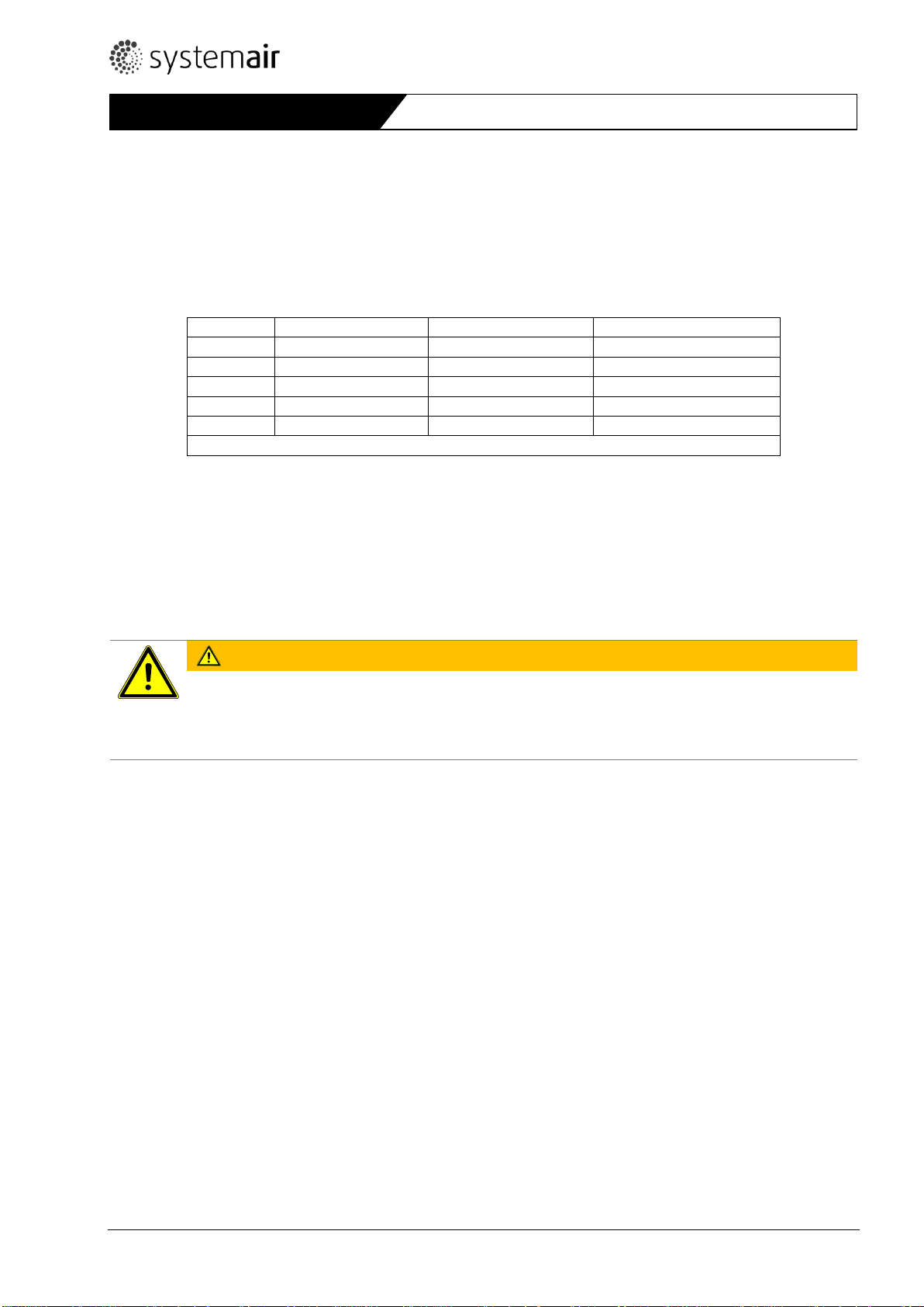
MRH
Impeller diameter*
Max. fan casing length
~ Weight without fan
Size
mm
mm
kg
400 – 630
400 – 630
540
212
710 – 800
710 – 800
700
248
900 - 1000
900 - 1000
700
303
1120
1120
1000
362
* Impeller diameter corresponds to MRH size
WARNING
Hazard from falling parts!
Check the roof before installation for load capacity/strength.
When selecting the hoisting device and fitting material observe the weight, tendency to vibrations and
shear forces (weight information on the nameplate).
Description
5 Description
The casing is made as a double metal layer with mineral wool insulation. The hatch casing is made of pre-galvanised
steel while the hatch cover of AlMg3. Insulation thickness: walls 120 mm (k = 0,29 W/m2K), cover 150 mm. Directly
powered impeller from aluminium alloy is arranged with the motor inside the air flow. Impeller is fastened together
with hub and secured screw directly on to the motor shaft. Dynamically balanced to ISO 1940 T1, class G6,3. Electrically operated spindle actuator for cover opening.
5.1 Technical data
5.2 Dimensions
Please see Appendix 1 or www.systemair.com.
6 Installation
6.1 Safety information
6.2 Preconditions for installation
MRH must be installed on roofs.
They can be mounted on a flat or inclined roof on an appropriate roof frame (observe load capacity, stiffness, insu-
lation).
The sidebars are adjustable to roof pitch. Possibility to adjust depends on the height position of sidebars.
Installation on flat surface (e.g. concrete) or through the roof.
Extremely wind or turbulence exposed places should be avoided.
During installation the site must be protected from dust, moisture and weather influences.
6.3 Installation
Ensure secure access to the fan for maintenance and service.
Installation up to Appendix 2.
Fit the contact surface between MRH and the roof frame with a sealing tape (not provided with MRH).
Before and after mounting check manually if the impeller rotates smoothly. Install the fan only, if the minimum air
gap between rotor and nozzle matches the value from the fan`s test protocol.
MRH shall be fixed with bolts or studs to the roof frame through the sidebars and position secured with screws.
Avoid distortions of the casing at installation. Check the air gap impeller/housing after fixing the MRH, the mini-
mum air gap should remain over allowed minimum from the fan`s test protocol.
Ensure unobstructed and uniform intake into the fan as well as free outlet.
8 MRH 06.04.2017
Page 9

NOTE
In some cases, it is better to mount accessories before placing the MRH on the roof.
NOTE
It is recommended to install a flexible connection between the fan and duct to avoid eventual tensions or
distortions of the casing (appropriate flexible connection should take eventual thermal extension of connecting parts). Flexible connection has to comply needed temperature/time; also as certified Systemair
accessory available.
NOTE
Data of accessories are on-line available (www.systemair.com).
NOTE
If the fan motors have built-in PTC: more than two PTC chains may not be switched in series, as this can
lead to undefined cut-outs.
Maximum check voltage of PTC is 2,5 V.
The wiring diagram see Appendix 3.
Motor protection must be provided by the installer.
At AXC(F) and AXC(B) fans without PTC observe specific instructions of the fan.
Electrical connection
Install connecting ducts and accessories. The suction side of the fan is provided with a connection for flange-type
mounting of the air duct according Eurovent 1/2, dimensions see Appendix 1 or www.systemair.com.
Provide for contact/suction protection and safety distances according to EN ISO 13857.
Provide flashing. Remove lifting eyes and store them.
7 Electrical connection
Fan: the wiring diagram of the fan is placed inside the cover of service switch. The quality and installation of cables for
electrical connection must ensure uninterrupted energy supply, even in case of fire. Inside fire zone, use only certified
cable. Connecting possibility see Appendix 3. Electrical data on the fan`s nameplate must comply with the provided
mains connection. Voltage tolerance according to IEC 38: +6%, -10%.
Hatch cover: it is opened by one or two 24VDC operated spindle actuators with push rod. Indication for
opened/closed cover position possible (floating limit switches on actuator). Connection of the hatch cover drive in the
actuator`s service switch. The wiring diagram of the hatch cover is placed inside the cover of service switch. Details
see Appendix 4.
The recommended start of the fan is 20 s after starting actuator for cover opening, to ensure vertical exhaust of hot
gases.
MRH 06.04.2017 9
Page 10
WARNING
Hazard from electrical voltage!
Electrical connection only by a trained electrician rsp. trained and instructed qualified personnel!
Electrical connection in accordance with the valid regulations.
Prevent the ingress of water into the connection box.
Observe 5 safety rules for the electrical expert!
- disconnect from the power supply (all-pole),
- prevent switching on again,
- test absence of voltage,
- earthing and short-circuiting,
- protect adjacent live parts by covers and barriers and fit a suitable warning notice.
CAUTION
Property damage as a result of motor overheating
The motor can overheat and be destroyed if the PTC not been connected.
PTC always connect to a motor protective device!
Commissioning
Connect the cable according to wiring diagram.
Tighten the nuts of cable glands well to achieve IP68 protection.
Check, if the cover of service switch is uniformly fastened. If there is a danger of unintended switch off of the
service switch, it should be locked to guarantee operation in fire case. Drill a hole into the handle in the “on”
position and provide with a padlock (not supplied with the fan). See Appendix 3.
Place the supply cable.
7.1 Residual current circuit breaker
Use universal RCDs type B or B+ in case of speed control with frequency converter. See also specific fan instruc-
tions.
7.2 Connection of thermal protection
8 Commissioning
8.1 Preconditions
Mounting and electrical connection have been correctly performed.
Installation residuals and foreign objects have been removed from the fan and ducts.
Inlet and outlet are free.
The safety devices have been fitted (protection against contact).
The protective conductor and external earth conductor have been connected.
The thermal protection is properly connected to the motor protective device:
- the motor protective device is functional;
- the thermal protection is functional.
The cable glands are tight.
Provided mains connection complies with the data on the nameplate.
The current (from the nameplate) does not exceed the mains data.
Service switch of the fan is in off position and the actuator`s service switch is in (middle) position 0.
The device is electrically connected to power supply.
Attached instructions of the fan and actuator have been understood.
10 MRH 06.04.2017
Page 11

WARNING
Hazard from electrical voltage!
Commissioning by trained and instructed qualified personnel only!
DANGER
Hazard from touching impeller, if not covered with protective grid!
The outlet protective grid is serially provided.
WARNING
Hazard from bursting parts!
When checking the direction of rotation, wear safety goggles.
WARNING
Hazard from electrical voltage and flying parts!
Errors occurring can lead to personal and/or property damage!
Observe 5 safety rules for the electrical expert!
- disconnect from the power supply (all-pole),
- prevent switching on again,
- test absence of voltage,
- earthing and short-circuiting,
protect adjacent live parts by covers and barriers and fit a suitable warning notice.
Commissioning
8.2 Commissioning
Check: service switch of the fan is in off position and the actuator`s service switch is in 0 (middle) position.
Check also the instructions of the fan – since different fans can be built in, different requirements could ap-
ply.
Check if the power supply is provided.
Switch the actuator`s service switch to position 1 (open the cover). It takes up to 30s to fully open (check).
Switch the fans’ service switch on for 2-3s and immediately off. Check direction of rotation if complies with the
arrow on the casing. If not, two phases need to be swapped – either in the service switch or in electrical cabinet.
After swapping check:
- the direction of rotation. Switch the fan for a short period on and then off to check the direction of rotation
of impeller, if complies with the arrow on the casing.
- leave the fan running, check, if running smoothly (eventual vibrations and noise);
- measure current with appropriate instrument (it may exceed nominal current by a max. 5%);
- tightness of all joints.
Fill in the attached test protocol of the fan and submit it in case of warranty claim.
Switch the actuator`s service switch to position 2 (close the cover). It takes up to 30s (check).
MRH 06.04.2017 11
Page 12
DANGER
Hazard from crushing/shearing by the hatch cover!
The hatch cover can be stopped in any position by turning the actuator`s service switch to middle (0) position.
WARNING
Hazard from electrical voltage and flying parts!
Errors occurring can lead to personal and/or property damage!
Switch the fan off as planned:
In cases of a non-typical noise from bearings, vibrations, pressure pulsation.
In case of overcurrent, overvoltage or temperature (nameplate).
NOTE
At single speed motors with nominal power from incl. 5,5 kW (D400V) we recommend “star – delta” start-
ing or soft start. For this purpose, all 7 wires are led to connection box/service switch.
DANGER
Hazard from touching impeller, if not covered with protective grid!
The outlet protective grid is serially provided.
DANGER
Hazard from crushing/shearing by the hatch cover!
The hatch cover can be stopped in any position by turning the actuator`s service switch to middle (0) position.
Operation
Check the functioning of system – observe instructions of actuator, especially intermittence and time of pres-
ence of control voltage (see also Appendix 4).
After checking set the actuator`s service switch to position 1 (ready to open) and secure it.
9 Operation
9.1 Operation/use generally
Only use the fan in accordance with this operating instruction and the operating instructions of motor.
Control the fan during operation for correct function.
Switch the fan off as planned.
9.2 Emergency use (use in case of fire)
Serially equipped MRH is intended for emergency use only. Access to hazardous zone is allowed and possible with observing safety measures for maintenance and service only.
Observing safety measures, it is to assure:
Safety components must not be bypassed or put out of function.
Prevent sucking of foreign particles, this can destroy the fan.
The fan may operate only within the limits declared on the nameplate.
In case of fire, bridging of motor protective devices is necessary to assure operation. Switch on max. speed even
after eventual short supply cut off must be assured.
12 MRH 06.04.2017
Page 13
ATTENTION
Hazard with risk of additional costs
Check provisions for speed control in the instruction of the fan (usually it is recommended a combina-
tion of frequency converter and appropriate all-pole sinus filter or minimum dU/dt filter).
At frequency controlled units additional EMC protection of cable and service switch could be needed
(on request).
Subsequently fitting of EMC shielded cable from motor to connection box/service switch is connected
with disassembly of the fan!
The motors cannot be voltage-controlled! The motor can overheat due to increased current at lower
voltage.
Operation
9.3 Dual use of hatch + fan (daily powered ventilation + emergency use)
In addition to serially equipped device it is necessary to provide following safety measures:
Protective guard to completely prevent access to opened/closed hatch cover – it is to provide by installer up to
roof design.
Hazard signs.
Once safety assured with above measures, it is to observe:
Safety components must not be bypassed or put out of function.
Prevent sucking of foreign particles, this can destroy the fan.
Switching frequency:
- the fan is intended for S1 continuous operation!
- the control equipment must not allow any extreme switching!
The fan may operate only within the limits declared on the nameplate.
In case of fire, bridging of motor protective devices is necessary to assure operation. Switch on max. speed even
after eventual short supply cut off must be assured.
If frequency converter is used for normal ventilation, it must be bridged in case of fire – see also instruction of
the fan.
In case of speed control via frequency converter - min. 20 Hz ÷ max. 50 Hz (rsp. 60 Hz, if declared for 60 Hz), make
sure that the voltage peaks on the connection terminals of the fan are lower than allowed in the fan`s instruction.
9.4 Dual use of hatch + fan (daily natural ventilation + emergency use)
In addition to serially equipped device it is necessary to provide following safety measures:
Protective guard to completely prevent access to opened/closed hatch cover – it is to provide by installer up to
roof design.
Hazard signs
Once safety assured with above measures, it is to observe:
Safety components must not be bypassed or put out of function.
Prevent sucking of foreign particles, this can destroy the fan.
Switching frequency of hatch must be in accordance with the actuator`s instructions, especially intermittence and
time of presence of control voltage (see also Appendix 4).
Weather protection devices should be applied to limit use (rain, strong wind).
The fan may operate only within the limits declared on the nameplate.
In case of fire, bridging of motor protective devices is necessary to assure operation. Switch on max. speed even
after eventual short supply cut off must be assured.
MRH 06.04.2017 13
Page 14

DANGER
Hazard from touching impeller, if not covered with protective grid!
The outlet protective grid is serially provided.
DANGER
Hazard from crushing/shearing by the hatch cover!
The hatch cover can be stopped in any position by turning the actuator`s service switch to middle (0) position.
WARNING
Hazard from electrical voltage!
Trouble setting and service only by a trained electrician or trained and instructed qualified personnel!
Observe rules for safe work while troubleshooting!
Observe 5 safety rules for the electrical expert!
- disconnect from the power supply (all-pole),
- prevent switching on again,
- test absence of voltage,
- earthing and short-circuiting,
- protect adjacent live parts by covers and barriers and fit a suitable warning notice.
CAUTION
Danger from hot surfaces!
During maintenance and cleaning wear protective gloves!
Maintenance/troubleshooting
10 Maintenance/troubleshooting
At maintenance and service observe:
Impeller must stand still;
Electrical circuit must be interrupted and secured against restarting;
Observe the rules for safe work.
Only then the outlet protective grid can be temporarily removed.
14 MRH 06.04.2017
Page 15
Possible reasons
Action
The ventilator
does not run
Connection to the mains fault.
Thermal protection triggers.
Motor fault.
Check connection to the mains and thermal protection. If
ok. check electric motor (winding resistance, resistance to
ground). If necessary get the electric motor repaired.
Air volume is
too low
Wrong direction of rotation.
Too high pressure drop in system.
Obstacles in duct.
Check the direction of rotation. If wrong, swap the supply
connection of any 2 phases. Check if current is similar all
phases. If ok. check operating point and system design.
Thermal protection of the
fan switches
off
Short-circuit.
Damage to the bearings.
Impeller blocked or grinding.
Compare connection with wiring diagram. Compare the
data of electric motor with setting of thermal protection.
If ok. check power supply and electric motor. Get the
electric motor or if necessary the complete fan repaired.
Overcurrent
Check the direction of rotation. If wrong, swap any 2
phases. Check if current is similar all phases.
Noise
Damage to the bearings.
Impeller blocked or grinding.
Get the electric motor or if necessary the complete fan repaired.
Loose fit on the base plate or motor support.
Tighten the bolts, look for the cause of vibrations.
Vibrations
The actual pressure drop of the
system is higher than supposed,
the fan could operate in an unstable area of the fan curve.
Check operating point and system design. Consult customer service of the manufacturer.
Damage or dust layer on impeller.
Clean the impeller, if necessary balance it or replace it.
The hatch
cover doesn`t
fully open
(~70°) ore fully
close
Obstacle.
One or both actuators is faulty
(MRH 1120).
Check, if the actuator is (are) powered.
Limit switch indicates, if the end position is reached.
Replace faulty actuator.
The hatch
cover operation is opposite
Wrong polarity on the actuator`s
service switch.
Swap it, check the control cabinet.
Maintenance/troubleshooting
10.1 Malfunctions and troubleshooting (generally)
If the reason for malfunction cannot be clearly determined, consult the customer service of manufacturer.
10.2 Cleaning
Regular cleaning prevents unbalance.
Keep casing and accessories clean and clean them if necessary with a brush (do not use a steel brush or high-
pressure cleaner). Do not use any detergents for interior cleaning.
10.3 Maintenance, service
Basically the fan or MRH may be repaired at the manufacturer only! Exceptions are non-relevant components. For further instructions consult the manufacturer.
The fan is by built-in for-life lubricated ball bearings as far as possible low-maintenance product. After their life time
(app. 20.000 h up to manufacturer, but expected 30.000 – 40.000 h due to low load), a replacement of the bearings is
necessary. Observe attached instructions of motor manufacturer/specific fan instructions.
Pay attention to a non-typical noise from bearings.
For damages (e.g. damage to winding) please contact our Service Department. You will find the address on the
back of these operating instructions.
Expected lifetime of actuators is at least 10.000 cycles.
MRH 06.04.2017 15
Page 16

VDMA
24186-1
Description
Maintenance interval
Monthly
Every
3 months
Once
a year
Fan and electric motor of the fan
1.1.11
Check the drainage for function
×
6.1.1
Check to dirt, damage, corrosion and fastening
×
6.1.2
Functional cleaning
×
10.1.6
Check the terminals for tightness
×
10.1.9
Test the fan for function und operational readiness
(test run app. 15 min.)
×
6.1.4
Check the bearings for noise
×
10.1.3
Check impeller for direction of rotation (all speed)
×
6.1.3
Check impeller if damaged or unbalanced (if necessary provide vibration measurement)
×
10.1
Functional test of automatically bridging of all thermal and overcurrent protective devices
×
10.1.7
Measure the current
×
10.1.12
Test function of protective device
×
Triggering device
Check it for function
×
Test of functions
Test all functions of system from control panel as
well as signal lights
×
Test of hatch opening/closing
Check the joints of actuator and hatch cover are
properly fastened
×
Check if smoothly opens/closes
×
Check the safety measures (protective elements,
signs, guards)
×
Accessories (air ducts, air louvers, flaps, sound attenuators)
5.5.1
Check accessible ducts inclusive fire protective insulation and fastening for outside damages and corrosion (visually)
×
5.5.4
Check accessible flexible connections for tightness
(visually)
×
5.2.1
5.2.3
Flaps and sound attenuators check for dirt, damage
and corrosion
Check mechanical functionality of the flaps
×
5.1.1
Check air louvres for dirt and damage (visually)
×
Maintenance/troubleshooting
Maintenance and check points of fans similarly to VDMA 24186-1 (type, scope and maintenance intervals to be specified in dependence of use and operating conditions).
10.4 Spare parts
In case of order of spare parts please specify the serial number of the MRH. You can find it on the nameplate or in the
test protocol.
Spare parts: electric motor (there is a restriction to use only from the test lab allowed motors), impeller, service
switches, actuator.
How to replace electric motor, impeller or actuator - please contact manufacturer for instructions.
16 MRH 06.04.2017
Page 17

DANGER
Hazard from crushing/shearing by the hatch cover!
The hatch cover can be stopped in any position by turning the actuator`s service switch to middle (0) position.
WARNING
Hazard from electrical voltage!
Disconnection and uninstalling only by a trained electrician or trained and instructed qualified person-
nel!
Observe 5 safety rules for the electrical expert!
- disconnect from the power supply (all-pole),
- prevent switching on again,
- test absence of voltage,
- earthing and short-circuiting,
- protect adjacent live parts by covers and barriers and fit a suitable warning notice.
CAUTION
Danger from cutting edges and impact!
Wear protective gloves when dismounting!
Dismount carefully.
WARNING
Hazard from falling parts!
When selecting the hoisting device observe the weight (weight information on the name plate).
Uninstalling/dismounting
11 Uninstalling/dismounting
Carefully disconnect all wires.
Remove the fan from duct. Carefully remove the fastening material.
Lift the MRH with an appropriate hoisting device on the provided lifting eyes. Place the MRH on appropriate
pallet.
12 Disposal
12.1 Disposal of the fan
Should the fan be disposed, proceed as follows:
Disassemble the fan into its components.
Separate the parts according to
- reusable material
- material groups to be disposed (metal, plastics, electrical parts, etc.)
Provide for the recycling of material. Consider the national regulation.
12.2 Disposal of packaging
Provide for the recycling of material. Consider the national regulation.
MRH 06.04.2017 17
Page 18

Appendix 1: Dimensions
Lifting eye position
18 MRH 06.04.2017
Page 19

Appendix 2: Installation examples
1 - Three height positions of sidebars (0, 250, 500 mm
from the bottom);
2 - The sidebars adjust to the roof pitch and fasten all
bolts (2 or 3 bolts each sidebar, depending on the
sidebar position);
3 - Fasten the bars to the roof frame with bolts or
studs;
4 - Fasten the sidebar with attached screws to the
wall of MRH;
5 - Remove the hinges.
*The MRH centreline can deviate from the vertical for max. +/- 5° - this can be combined with the sidebar setting.
**Avoid additional load to accessories due to weight of eventual duct with flexible connection
*** The position of service switches/direction of opening to ridge (left-right) choose considering access/snow depo-
sition/wind/pitch. Roof insulation and flashing is not shown in the installation examples.
MRH 06.04.2017 19
Page 20

MRH
~HG
1
2
3
4
5
400 - 630
0
0 – 12°
250 0 – 12°
500
0 – 2°
min 21°
max. 33°
MRH
~HG
1
2
3
4
5
710, 800 0 0 – 12°
250 0 – 12°
500
0 – 2°
min 20°
max. 31°
MRH
~HG
1
2
3
4
5
900, 1000
0
0 – 9°
250 0 – 9°
500
0 – 2°
min 14°
max. 21°
MRH
~HG
1
2
3
4
5
1120 0 0 – 9°
250 0 – 9°
500
0 – 2°
min 12°
max. 19°
Possible vertical positions and adjustment of sidebars to roof pitch
The sidebars can be upon request ordered to meet specific roof pitch.
20 MRH 06.04.2017
Page 21

Y 400V…STARTING, D 400V…OPERATION (PTC could be an option!)
Single speed motor >= 5,5 kW
See IMO, Chapter 7
1
M25x1,5
Power supply
d max. 4 mmq
D max 16,5 mm
2
M16x1,5
PTC
d max. 1,5 mmq
D max 10 mm
3
M32x1,5
-
1
M32x1,5
Power supply
d max. 6 mmq
D max 18 mm
2
M16x1,5
PTC
d max. 1,5 mmq
D max 10 mm
3
M25x1,5
-
Appendix 3: Wiring diagram, connection
1
2
3
1
2
3
DVAX, DVAX-BPN, DVAX-BPF 1000D4-M
DVAX, DVAX-BPN, DVAX-BPF 1000D4-L
DVAX, DVAX-BPN, DVAX-BPF 1120D6-L
AXC(B), AXC(F) <=22 kW
930637
MZ0651800777
930638
MZ0751800644
DVAX, DVAX-BPN, DVAX-BPF 1000D4-S
DVAX, DVAX-BPN, DVAX-BPF 1120D6-M
AXC(B), AXC(F) <=7,5 kW
When choosing AES exhaust air and smoke extraction control accessory, please observe serial connecting capability
of the fan`s service switch.
MRH 06.04.2017 21
Page 22

3
2
1
Appendix 4: Connection of actuator
930712
MZ0551801582
Connection of actuator in the actuator`s service switch
* connect to 24VDC (+30/-20%)
** NO/NC are intended to control position of the actuator`s service switch (ON - OFF)
Warning: the control voltage 24VDC to open or close hatch cover should apply max. 6 minutes! This is to ensure by
control system (use actuator`s internal floating limit switches as indication of cover position to cut off the control
voltage).
The connection cable to service switch calculate with max. 1V voltage drop at max. load!
Operating mode for peak load at 25°C ambient: S2 1min
Operating mode for continuous load at 40°C ambient: S3 5% (example: open in 30s, then wait 9min 30s)
Max. current of actuator(s) at SL 1000 (rated MRH load):
MRH 400, 450, 500, 560, 630: 4A
MRH 710, 800: 6A
MRH 1000: 8A
MRH 1120: 2x8A=16A
Functions of the actuator`s service switch:
Position 0: stop (NO – opened contact, NC – closed contact) – SAFETY POSITION
Position 1: open hatch cover (NO – closed contact, NC – opened contact) – WARNING!
Position 2: close hatch cover (NO – opened contact, NC – closed contact) – DANGER!
Connection of actuator`s internal floating limit switches in the actuator`s service switch (1 actuator up to MRH
1000)
*** drawn position - closed hatch
1-2 opened, 2-3 closed in closed hatch position
1-2 closed, 2-3 opened in opened hatch position
1-2 closed, 2-3 closed in any intermediary position of the hatch cover
Potential free NC contacts, load capacity 24VDC/1A
Connection of actuator`s internal floating limit switches in the actuator`s service switch (2 actuators at MRH 1120)
*** drawn position - closed hatch
1-2, 4-5 opened, 2-3, 5-6 closed in closed hatch position
1-2, 4-5 closed, 2-3, 5-6 opened in opened hatch position
1-2, 4-5 closed, 2-3, 5-6 closed in any intermediary position of the hatch cover
Potential free NC contacts, load capacity 24VDC/1A
22 MRH 06.04.2017
Page 23

DANGER
Hazard from touching impeller, if not covered with protective grid!
The outlet protective grid is serially provided.
DANGER
Hazard from crushing/shearing by the hatch cover!
The hatch cover can be stopped in any position by turning the actuator`s service switch to middle (0) position.
Appendix 5: Mechanical hazards, safety warnings
MRH 06.04.2017 23
Page 24

 Loading...