

SystemAir MAXK Series, MAXK-I3 DC Series, MAXK-I3 2000 DC, MAXK-I3 3000 DC, MAXK-I3 4000 DC Installation And Operating Instructions Manual
...Page 1
MAXK
Installation and Operating Instructions
Document in original language | ·
GB
Page 2

© Copyright Systemair AB
All rights reserved
E&OE
Systemair AB reserves the rights to alter their products without notice.
This also applies to products already ordered, as long as it does not affect the previously agreed specifications.
|
Page 3

Contents
1 Declaration of Incorporation........ ..... ......... ..... ....1
2 General information ..... ..... ..... ......... ..... ..... ..... ..2
2.1 Notice symbols . ..... ..... ......... ..... ..... ..... ...2
2.1.1 Instruction symbols.. ......... ..... .....2
2.2 Notes on the documentation ..... ..... ..... .....2
3 Warnings. ..... ..... .............. ..... ..... ......... ..... ..... .2
4 Product information ... ..... ..... ..... ..... ......... ..... ....3
4.1 General... .... ..... ..... ..... .............. ..... ..... ..3
4.2 Power range ........ ..... ..... ..... ......... ..... ....3
4.3 Dimensions... .... ..... ..... ..... ......... ..... ..... ..4
4.4 Technical data ......... ..... ..... ..... ......... ..... .4
4.5 Acoustics.... ..... ..... ..... .... ..... ..... ..... ........5
5 Transport and storage . ..... ..... ..... .... ..... ..... ..... ...5
5.1 General... .... ..... ..... ..... .............. ..... ..... ..5
5.2 Crane transport........ ..... ..... ..... ......... ..... .6
5.3 Forklift transport ... ..... ..... ..... ......... ..... ....6
5.4 Big units ..... .... ..... ..... ..... ..... ......... ..... ....6
5.5 Storage on the construction site . ......... ..... .6
6 Installation.. .............. ..... ..... ..... ......... ..... ..... ...7
6.1 Installation site ..... ..... ..... ..... ......... ..... ....7
6.1.1 Roof installations ... .... ..... ..... ..... .7
6.2 Operating doors ........ ..... ..... .............. ..... 7
6.3 Mounting of device units.... .... ..... ..... ..... ...7
6.4 Mounting steps... ..... ..... ......... ..... ..... ..... .8
6.5 Mounting indications for the kind of
delivery: „dismantled assembly
group“ ... ..... ..... ......... ..... ..... ..... .... ..... ...9
6.5.1 Unit profile... .... ..... ..... ..... ......... .9
6.6 Mounting indications for wet
parts .... ..... ..... .............. ..... ..... ..... .... .. 10
7 Internal components .... ..... ..... ......... ..... ..... ..... 10
7.1 V-cell-filter ..... ......... ..... ..... ..... ......... ... 10
7.2 Air heater, air cooler and glycol-
compound system ..... ..... .... ..... ..... ..... ... 11
7.3 Steel-galvanized registers ........ ..... ..... ....11
7.4 Electrical heater . ......... ..... ..... ......... ..... . 12
7.5 Counter flow plate heat
exchanger ..... ..... ..... ......... ..... ..... ..... ... 12
7.6 Jalousie damper ... ..... ..... ..... .............. ... 13
7.7 Doors and door locks..... .............. ..... ..... 13
7.7.1 Interception safety ..... ......... ..... 13
7.8 Silencer. ..... ......... ..... ..... ..... ......... ..... .. 13
7.9 Internal lightening ..... ..... ......... ..... ..... ... 13
7.9.1 Roof units ..... ......... ..... ..... ....... 14
8 Syphon ..... .... ..... ..... ..... ..... ......... ..... ..... ..... .. 14
8.1 Syphon for cooler ......... ..... ..... ..... .........15
8.1.1 General information ..... ..... ..... ... 15
9 Outdoor installation . ......... ..... ..... ......... ..... ..... 16
9.1 Roof frame made of galvanized
sheet. ......... ..... ..... ..... ..... ......... ..... ..... 17
10 Condensation and heat insulation . ..... ......... ..... . 18
11 Maintenance.... ..... ..... ......... ..... ..... ......... ..... . 18
11.1 Warnings. ..... .............. ..... ..... ..... ......... 18
11.2 General... .... ..... ..... ..... ..... ......... ..... ..... 19
11.3 Maintenance instructions ......... ..... ..... ....19
12 Disturbances and troubleshooting .... ..... ......... ... 21
|
Page 4

Page 5
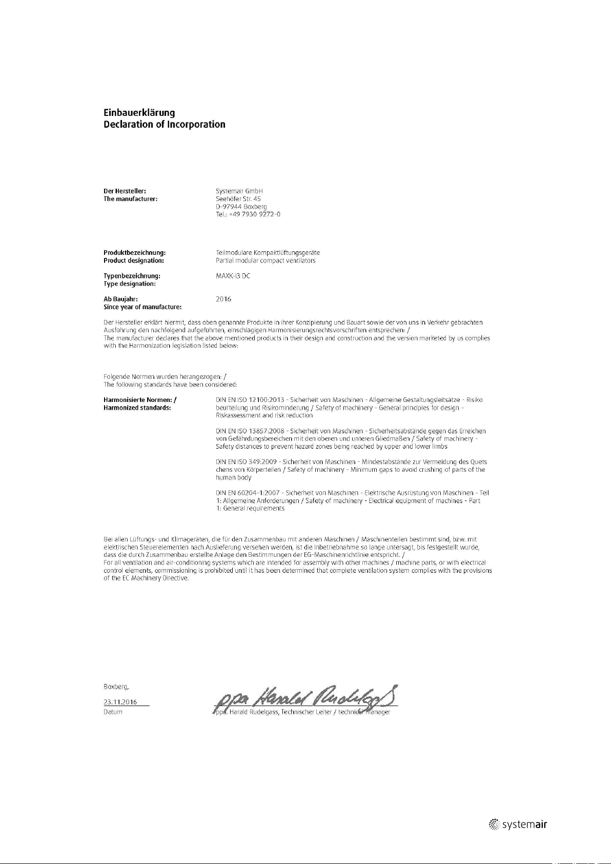
1 Declaration of Incorporation
Declaration of Incorporation |
1
|
Page 6
| General information
2
2 General information
2.1 Notice symbols
Danger
Direct hazard
Failure to comply with this warning leads directly to death or to serious bodily harm.
Warning
Potential hazard
Failure to comply with this warning possibly leads to death or serious bodily harm and damage to objects.
Caution
Hazard with a low risk
Failure to comply with this warning may potentially lead to moderate injuries or/and damage to objects.
Important
Hazard with risk of damage to objects
Failure to comply with this warning will lead to damage to objects.
Note:
Useful information and instructions
2.1.1 Instruction symbols
Instruction
♦ Carry out this action
♦ (if applicable, further actions)
2.2 Notes on the documentation
Warning
Hazard as a result of improper handling of the fan
These operating instructions describe the safe use of the fan.
♦ Read the operating instructions completely and carefully!
♦ Keep the operating instructions and other valid documents, such as the circuit diagram or motor
instructions, with the fan. They must be permanently available at the place of use.
Instruction with xed sequence
1. Carry out this action
2. Carry out this action
3. (if applicable, further actions)
3 Warnings
The following admonitions will be presented in the different sections of the document.
Danger
• Make sure that the Mains supply to the unit is disconnected before performing any maintenance or
electrical work!
• All electrical connections must be carried out by an authorized installer and in accordance with local rules
and regulations.
|
Page 7

Product information |
Warning
• Keep the doors locked during operation to ensure required level of safety for the unit.
• The unit must be duct connected or in some other way provided with protection so that it is not possible
to come in contact with the fans through the duct connections
• Beware of hot surface an the heating battery during maintenance and service.
• The unit is heavy. Be careful during transport and mounting. Risk of injury through pinching. Use
protective clothing
• Beware of sharp edges during mounting and maintenance. Make sure that a proper lifting device is used.
Use protective clothing.
• The units electrical connection to the mains supply must be preceded by an all pole circuit breaker with a
minimum 3 mm gap.
Caution
• If the unit is installed in a cold place make sure that all joints are covered with insulation, and tape well
• Duct connections should be covered during storage and installation
• Do not connect tumble dryers to the ventilation system
• Take care not to damage the water battery when connecting water pipes to connectors. Use a spanner to
tighten the connection.
3
4 Product information
4.1 General
This installation manual concerns air handling unit type MAXK-I3 DC.
• Model: MAXK-I3 2000 DC, MAXK-I3 3000 DC, MAXK-I3 4000 DC, MAXK-I3 5000 DC, MAXK-I3 6000 DC, MAXK-I3
7000 DC
• Wall thickness: 50mm. T3/TB3 (DIN EN 1886) casing T2/TB2 or T1/TB1 on request
The MAXK-I3 DC series is a passive house certified air handling unit. The air handling units with heat recovery consists
of a counter flow plate heat exchanger with integrated bypass, supply and exhaust air fan with EC motor and an outdoor- and extract air filter. Six sizes in modular design with extendible accessories like damper, recirculating air damper,
heater modules, cooling modules and silencer. This manual consists of basic-information and recommendations concerning the design, installation, start-up and operation, to ensure a proper fail-free operation of the unit. The key to
proper and safe operating of the unit is to read this manual thoroughly, use the unit according to given guidelines and
follow all safety requirements.
4.2 Power range
|
Page 8
| Product information
4
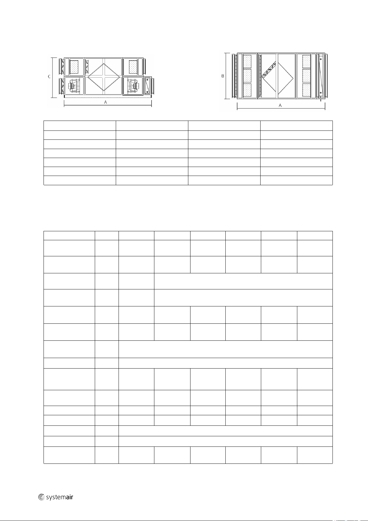
4.3 Dimensions
MAXK-I3 DC A B
2000 DC 3326 800 1664
3000 DC 3486 1120 1664
4000 DC 3586 1600 1664
5000 DC 3686 1900 1664
6000 DC 3686 2280 1664
7000 DC 2786 2600 1664
* incl. 100 mm base frame.
(dimensions in mm)
C*
4.4 Technical data
MAXK-I3 2000 DC 3000 DC 4000 DC 5000 DC 6000 DC 7000 DC
Non-residential
construction
At an external
pressure of*
Residential
construction
At an external
pressure of*
Effective heat
recovery rate
Electric power
consumption
Type of heat
exchanger
Fan motor
max. power
consumption of a
fan
Supply voltage of
the fans
Phases
Frequency Hz
Filter Outdoor air F7 / extract air M6
Integrated bypass Available
Duct connection
(W x H)
m³/h
Pa 217 242 270 290 299 328
m³/h
Pa 190
% 84 84 84 84 84 87
Wh/m³
W 423 1000 1400 1850 2730 2730
V 200... 277 380... 480 200... 277 380... 480 380... 480 380... 480
~
mm
600–1400 700–2200 800–3200 1100–4200 1300–5200 1400–6200
600–1600
0,39 0,45 0,45 0,45 0,45 0,43
1 3 1 3 3 3
50/60 50/60 50/60 50/60 50/60 50/60
658 x 638 976 x 638 1456 x 638 1756 x 638 2136 x 638 2456 x 638
Also suitable for application in residential construction
Also suitable for application in residential construction
Counter flow plate heat exchanger
Direct current (EC technology)
|
Page 9
Transport and storage |
5
Total weight
without heating
battery
Total weight with
heating battery
* with built in filters (outdoor air F7 and extract air M6).
Additional installed units such as, for example, heating battery reduce the available external pressure
kg
kg
880 1000 1200 1390 1620 1840
956 1093 1330 1521 1792 2031
4.5 Acoustics
MAXK-I3 DC
2000 DC
3000 DC
4000 DC
5000 DC
6000 DC
7000 DC
* Operation at the upper limit.
dB(A)
dB(A)
dB(A)
dB(A)
dB(A)
dB(A)
Sound level*
Casing
63,7 79,2 60,3 58,6 78,4
64,8 75,2 68,6 68,6 75,2
65,8 80,4 73,3 73,3 80,4
66,7 82,3 76,3 76,3 82,3
67,9 80,7 74,3 74,3 80,7
63,6 78,3 63,6 61,8 79,6
Supply air
Extract air
Outdoor air Exhaust air
5 Transport and storage
5.1 General
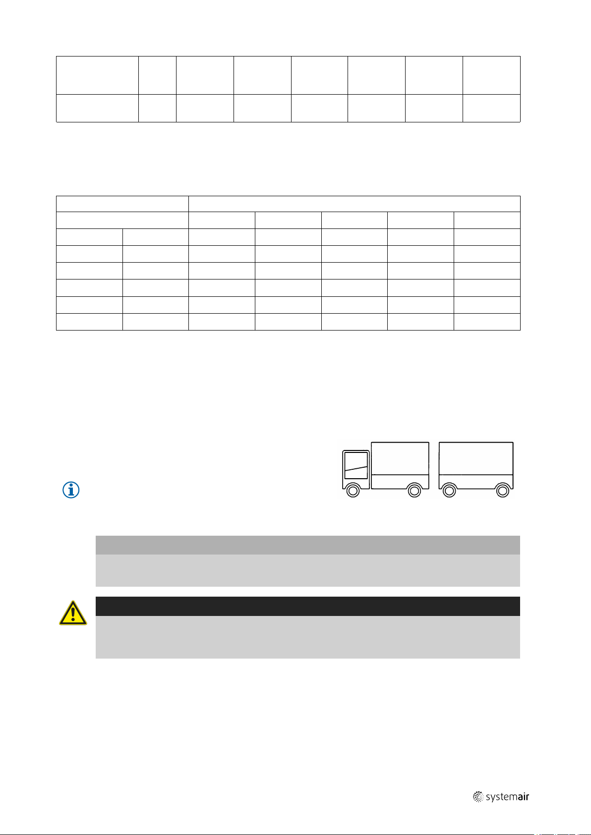
MAXK-I3 DC air handling units are delivered in transport
units. The width of the lorry (inside width approx. 2,34 m
) resp. loading level (inside width approx. 2,55 m – width
for a jumbo approx. 2,9 up to 3,05 m ) determine the
quantity of the single parts.
Note:
The quantiy of the single parts is shown in the
detailed drawing.
Important
• The shaft of the ventilator must always be arranged horizontally during the transport
• Units for outdoor installation with weather roof: weights without snow load!
Warning
• The unit is heavy. Be careful during transport and installation. Risk of injury through pinching. Use
protective clothing.
• The unit must not be put into operation before the enclosed parts are removed and installed properly.
|
Page 10
| Transport and storage
6
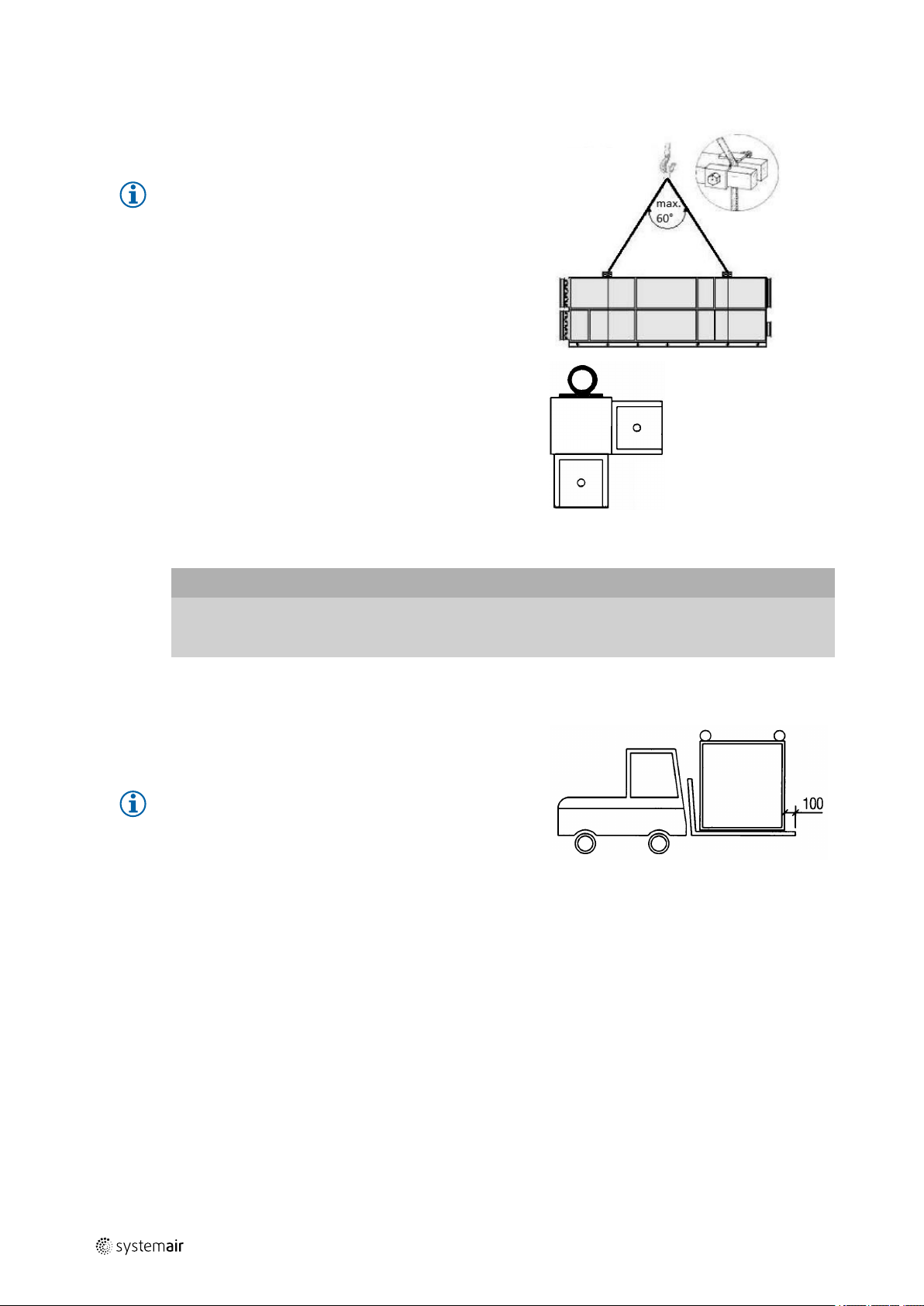
5.2 Crane transport
Small units are equipped with 2 eyebolts (diagonally
staggered), big parts with 4 eyebolts.
Note:
• load suspension device acc. to UVV188.4§4
• slope angle: 60°
• it must be guaranteed that the crane doesn’t
jerk
• „long“ ropes should be prepared to keep the
stipulated lifting angle
Grading of the eyebolts:
• M 16 up to 1300 kg wall thickness 50mm
• M 20 up to 2500 kg wall thickness 50mm
• over 2500 kg special measures
Important
After the mounting, the devices have to be protected against pollution, humidity at building site and
damages.
Outdoor units: Do not disassembly the lifting eyes after installation.
5.3 Forklift transport
Use only forks which extend to the whole width of the
single parts.
Note:
lenght of fork = width of equipment + approx.
100 mm
Too short forks cause damages at the range of the floor
covering.
5.4 Big units
Aluminium corner with internal
thread M16 up to M24.
Single parts with a total weight as from approx. 2000 kg resp. with heavy built-in parts as from approx. 800 kg have to
be transported to the place of destination with several lifting vans (3 – 4 lifting vans)
5.5 Storage on the construction site
If parts are packed in foil, it must be removed immediately after delivery. Foil supports water formation through
condensation and thus appearances of oxidation, especially on hot-dipped galvanized material.
Following measures are to be considered if parts cannot be brought immediately to the construction site:
♦ Remove foil
♦ Store units against atmospheric exposure at a protected temporary storage place.
♦ Close unit openings so that no dirt (dust, vermin, etc.) can penetrate.
|
Page 11

Installation |
6 Installation
6.1 Installation site
Floors, foundations, ceilings or steel construction must be checked as to the planeness. Unplaneness causes a more difficult mounting and the canting of the doors. The consequences among other things are doors which can heavily be
opened and which are untight.
Additional stripy foundations resp. cross slides are necessary as from a device width of 2,4 m (e.g.: ventilator parts consisting of 2 box parts because of maximal load width).
When choosing the location it should be kept in mind that the unit requires maintenance regularly and that the inspection doors should be easily accessible. Leave free space for opening the doors and for taking out the main components.
The outdoor air intake of the building should if possible be put in the northern or eastern side of the building and away
from other exhaust outlets like kitchen fan outcasts or laundry room outlets.
Warning
The devices have to be adjusted to vibration elements (Mafund, Asozell, Silomer a.s.o.) to avoid a
transmission of structure-borne noise and to guarantee the ventilation of the device base floor.
The unit must be duct connected or in some other way provided with protection so that it is not possible to
come in contact with the fans through the duct connections.
6.1.1 Roof installations
7
Roof units and roof platforms have to be fixed with screws to the delivered baseframe after the mounting to prevent a
slipping because of wind load. The drillings and screws have to be fixed on site.
Important
• wind load of the devices
• our weight indications of the devices do not include snow loads
6.2 Operating doors
The device is to be set up so that all operating doors can
be opened completely in order to carry out maintenance
work without hindrance (filter change, cleaning, etc.)
6.3 Mounting of device units
Important
♦ Tighten screws only after pushing the parts of the unit together!
♦ Appliances like bar clamps or winches are compulsory.
♦ Check elastic joints for cracks after assembly and in annual cycle, if necessary seal again.
|
Page 12

8
| Installation
Note:
The necessary screws and sealings for the mounting are attached loose to each delivery and deposited in
the ventilator part.
type term
A
B
B
C
C
Galvanized sheet, thickness: 2–3 mm
U-structural steel, rounded
U-structural steel, rounded U-100 und U-120
U-structural steel, DIN
U-structural steel, DIN U-100 DIN und U-
U-70 M8 x 20 mm
U-80 DIN M8 x 20 mm
120 DIN
screws
M8 x 20 mm
M8 x 25 mm
M8 x 25 mm
6.4 Mounting steps
With the following proceeding an expertly done installation is guaranteed. Thus the function of the devices is guaranteed and leakages at doors or device connections are prevented.
Step 1
Check the mounting surfaces as to their planeness.
Unplane mounting surfaces have to be mended with lined
stripes.
Step 2
Align the housing frame at the operating side first at the
bottom with a screw clamp.
Step 3
Insert bar into the crane eyes and align the housings
against each other. When required use a piece of wood as
a lever bar.
Step 4
Mount screws and nuts, but do not tighten them. Screwed
joints see
Step 5
Pull the housing frames together with the screw clamp in
the length direction of the unit. Check the device joints
and the planeness.
Step 6
Tighten the screws.
|
Page 13

Installation |
Important
Through jolting during the transportation bore chips can loosen from the bolting connections and fall on the
ground. Please vacuum these chippings immediately from the housing parts since rust spots can ensue.
6.5 Mounting indications for the kind of delivery: „dismantled assembly group“
• Kind of delivery: delivery of devices partially screwed resp. completely
dismantled
♦ Before plugging on the
device profiles, the stops
of the plug-in corners
have to be sprayed off
with a permanently
elastical mass.
♦ Duo-Taptite screws 8 x 16
cross recess Z
9
6.5.1 Unit profile
• door and ceiling parts are regularly designed as complete units, if the opening to bring in the parts, permits this.
|
Page 14
| Internal components
10
6.6 Mounting indications for wet parts
Cooler parts have to be mounted and filled very
thoroughly
7 Internal components
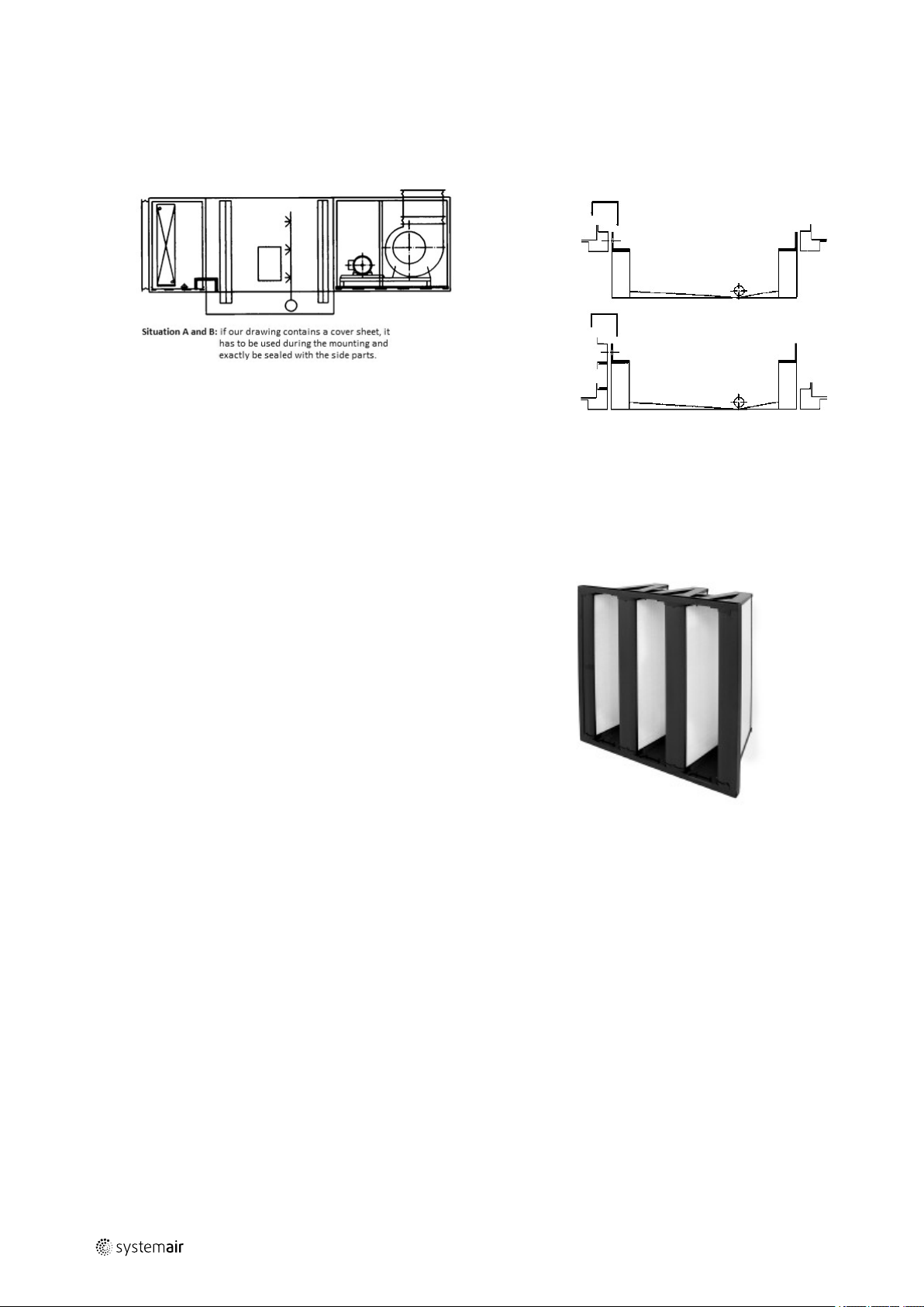
7.1 V-cell-filter
Due to its large filter surface has a high air throughput.
The pollution must be controlled with a differential
pressure device (U-tube, inclined tube). Filter cells have to
be renewed completely after the maximum difference
pressure has been reached. Check the standard frame as
to the correct fitting resp. check the sealing when
exchanging the filter. Torn filters and filters with low
qualitiy pollute built-in parts which are connected in
series. The bottom of the filter units must be cleaned
monthly (wipe – cleaning)
• Extract air filter = M6
• Supply air filter= F7
Detail A: tub protruding at the bottom
Detail B: tub flush at the bottom
|
Page 15

Internal components |
7.2 Air heater, air cooler and glycol-compound system
After the mounting of the heat exchanger units the ribbed surfaces must be covered to avoid mechanical damages.
The connection of the heat exchanger, air heaters as well as the coolers must be made de-energized. When
exchanging the filter, pollutions must be removed.
Heat exchangers: When connecting the supply and return lines the threaded cable glands must be protected against
twisting in counterpressing. Heat exchangers with copper collectors should be treated with caution. Register Cu-Alu
are suitabel for a max. temperature of 120°C and a pressure of 16 bar. Register steel galvanized are built differently.
Pressure minimum 6 bar, maximum 25 bar. In case of hot water resp. steam operation operate the ventilator with
slowing down time.
To avoid frost damages reliable sensors for the protection against frost must be installed. The ventilation must be
carried out thoroughly to avoid air in the register. When filling with water pay attention to leakages which could be
the result of transport or mounting damages (e.g. pay attention to the drilling into the waterways by mistake).
In connection with plastic separators a warming up via artificial heat must be avoided. (caution in case of heating
media with more than 90 ° C.)
In close range to the forerunning and reverse running connections, connections which can be locked up must be
provided and which at the same time can be used for measurements. Ventilation and drain valves in the pipes must
be put in on site.
If coolers are arranged in the fresh air and are operated with mixed temperature there is the danger that it freezes
up. The forerun gland is marked with a riveted plate. Check the supply and reverse running connections whether
they are correctly connected.
Mounting of the piping: General rule for Cu/Alu register. The water forerun has to be connected on that collector
which is situated very close to the air outlet. Attention: In case of mounting the connection must be made volt-free
and decoupled. The pipe connections at site must be dimensioned that way that no vibrations from the device to the
piping system or vice versa are transmitted. Also the connection to the heat transmitter itself must be made voltfree.
If the exchangers have indented supply and return stubs :
As from 3°C empty completely remaining water. Because of the danger to freeze up inform all responsible persons.
The ends of the collectors are not locked. If the pipes are not connected within 8 days we recommend to make them
blind, so that no unauthorized foreign parts can reach the collector.
11
Caution
• use only non-corrosive and suitable heating resp. cooling media
• the remaining water must be removed via compressed air to avoid frost damages
• water systems with glycol filling have to be adapted to the respective climatic zones
• after the pressure test with tap water there is the danger that it freezes up if no suitable mixture with
glycol is guaranteed
• protective means reduce the output transmission of the exchanger
• in case of cleaning the surface of the exchanger do not use high-pressure water or high-pressure steam
• the heat transmission segments can be deformed
• during the first operation hours punching oil remnants which cannot be avoided might exist
7.3 Steel-galvanized registers
• steam and water operation
Steam operation in connection with heat recovery should principally be avoided. In order to prevent stress cracks,
the transport fixing must be loosened after the mounting of the devices (Z-angle). The piping on site must be made
with compensators.
Important
• if plastic separators are closely arranged, the ventilators should be driven with slowing down time to
avoid radiant heat
• improper condensate conductors cause steam impacts and destroy the core pipes of the heat exchangers
|
Page 16

| Internal components
12
7.4 Electrical heater
The casing is made of Aluzinc-coated sheet steel, AZ 185,
that conforms to the requirements for corrosivity class C4.
The heater elements are made of stainless steel to EN
1.4301. The junction box includes the terminal blocks
necessary for the electrical connections. The electrical
heaters are produced to degree of protection IP43, but
are also available to IP55 of IP65 to special order. The
heaters are adapted for max 50°C outgoing temperature
and min. air velocity of 1.5 m/s.
All heaters have at least two overheating protections –
one with automatic reset and one with manual reset. All
duct heaters have the overheating protection reset button
on the heater cover.
A built-in regulator ensures simple installation, e.g. due to
fewer cable runs, which lowers the installation cost and
reduce the risk of incorrect wiring. The regulator is
electronic and controls the output across a triac by means
of time proportional control (intermittent ON/OFF
control). This provides very accurate temperature control.
Since control is electronic, it is entirely silent and sustains
a minimum of wear. On heaters with higher ratings, part
of the output are controlled by a step controller. However,
fine adjustment of the temperature is always carried out
by the electronic ON/OFF control.
Control by means of built-in regulator for 0…10V control
signal.
Follow the special instructions of the manufacturer!
Important
• Slowing down time, to avoid radiant heat.
7.5 Counter flow plate heat exchanger
MAXK I3 2000-7000 DC models are equipped with a
highly efficient, counterflow heat exchanger. The counter
flow heat exchanger is equipped with a 100% bypass.
This means that a damper is covering the counter flow
heat exchanger during deicing.In summer there is no
undesirable heat recovery. Plate material of noncorroding aluminum alloy. Required supply air
temperature is therefore normally maintained without
adding additional heat. The operation of the heat
exchanger is automatic and depends on the set
temperature. The heat exchanger is removable for
cleaning and maintenance. After a long time of use dust
may build up in the exchanger and block the airflow. It is
important to clean the exchanger regularly (once a year)
to maintain high efficiency. The heat exchanger can be
taken out of the unit for maintenance. Wash in hot soapy
water or use pressure air. Do not use detergent containing
ammonia.
|
Page 17

7.6 Jalousie damper
Jalousie flaps are equipped with polyamid-bearingsleeves. These need not be maintained (do not put oil or
grease on them). Please pay attention that the jalousie
flaps must be opened before switching on the ventilator
and that the ventilator must be switched off before the
closing of the jalousie flaps. If it is operated by hand the
housing part might be deformed. Impact loads f.ex. by
unsecured jalousie flaps lead to a destruction of housing
parts.
7.7 Doors and door locks
Doors and door locks must be checked whether they can
be locked and closed. Lubricate the movable parts.
Internal components |
13
7.7.1 Interception safety
Check the interception safety devices of the doors at
pressure side (release chains only after standstill of the
ventilators)
7.8 Silencer
To avoid fan noise being transferred via the duct system,
silencers should be installed both on supply and extract
air.
To avoid noise being transferred between rooms via the
duct system and also to reduce noise from the duct
system itself, installation of silencers before every inlet
diffuser is recommended.
The links of the sound absorbers have to be cleaned with
vacuum cleaners (depending on the pollution). Dirty
perforated sheets reduce the absorption qualities.
7.9 Internal lightening
Lights are wired on external terminal boxes. The wiring of
the terminal boxes between each other resp. from
component to component must be made on site.
Radiated heat in case of the medium steam resp. hot
water might lead to the damage of the lights and the
cables. Standstill damages in case of opening heating
valves
|
Page 18

| Syphon
14
7.9.1 Roof units
Lights are wired on internal terminal boxes. Internal
wiring of the terminal boxes between each other resp.
from component to component must be made on site.
8 Syphon
1a Rubber sleeve 40–30
1b Rubber sleeve 40–30
2 Jaining piece 40–40
3 Sleeve nut 1 1/2“
4 Sealing Ø 40
5 Arc Ø 40
6 Plunger tube Ø 40
7 Sleeve nut 1 1/2”
8 Bearing ring Ø 40
9 Sealing Ø 40
10 Terminal arc Ø 40
11 Sealing 1 1/2”
12 Check valve with drain
13 Sealing 1 1/2”
14 Screw cap 1 1/2”
15 Ball
16 Screw cap 1 1/2”
For each device drain a syphon must be provided. The installation can be
seen in picture 1. The length of the arc (5) and plunger tube (6) has to
be adapted to the existing negative pressure. In case of drains of ¾“ up
to 1 ½“ connecting elements and rubber sleeves are automatically
delivered (parts 1 to 5). The syphon may not be connected directly with
a drain conduction but it must be guaranteed that it can run out freely.
Before putting into operation the device or longer standstill periods the
syphon must be cleaned (cleaning 4 times a year). Also the drop
separators have to be cleaned half - yearly with a steam vacuum
cleaner. If there are several drains in one device then a separate syphon
has to be put on each sleeve. Do not connect on one common
conduction. If the syphons are regulary delivered a functional test must
be made in time to avoid water damages.
Note:
Other types of construction may only be used after consultation.
negative
pressure in
unit P (Pa)
2000
1900
1800
1700
1600
1500
1400
1300
1200
1100
1000
900
800
700
shortening
of the
plunger
tube no. 6
by mm
100
110
110
110
110
110
-
-
-
-
-
-
-
-
shortening
of the arc
no. 5 by
mm
-
10
20
30
40
0
10
20
30
40
50
60
70
|
Page 19

Ground clearance of the central units
The function and mounting of a syphon requires a
sufficient ground clearance of the respective device. The
minimum ground distance R to picture 2 is:
Important
In case of disregarding the base height the overflowing of the tub is preprogrammed
Syphon |
15
8.1 Syphon for cooler
Pressure operation:
Note:
For tubs which have to be connected within the overpressure range, hand – made syphons must be
installed. These must have a refilling piece. Drain problems can occur in connection with multi – speed
motors resp. with converter operation.
8.1.1 General information
• make a functional test with tap water in due time!
• use a separate syphon with free drain for each drain.
|
Correct installation
Page 20

| Outdoor installation
16
Negative pressure
9 Outdoor installation
Overpressure
Important
♦ If the weather protection roof cannot be bought immediately, the top of the unit must be covered
watertight.
♦ The outside joints of outdoor units have to be permanently elastic sealed. While assembly work the joints
must be proved. If necessary you have to reseal the joints. Please prove all joint gaps.
|
Page 21

kind of delivery. box sheets pre-punched drilling screws
4,8 x 19 loose
9.1 Roof frame made of galvanized sheet
Outdoor installation |
17
Cut: roof frame insulated (extra charge)
detail: drip ledge
Mounting of the drip ledge
♦ install, set up, bolt the device
♦ screw the drip ledge with a drilling screw
(4.8 x 19) at the device brace. Mount prefabricated corner parts and cut off the
intermediate parts.
♦ clean and degrease drip ledge and spray
with permanent elastic material very
thinly
|
Page 22
| Condensation and heat insulation
18
Top view
Important
It should be ensured that the base frame is insulated. Without insulation it can occur condensat.
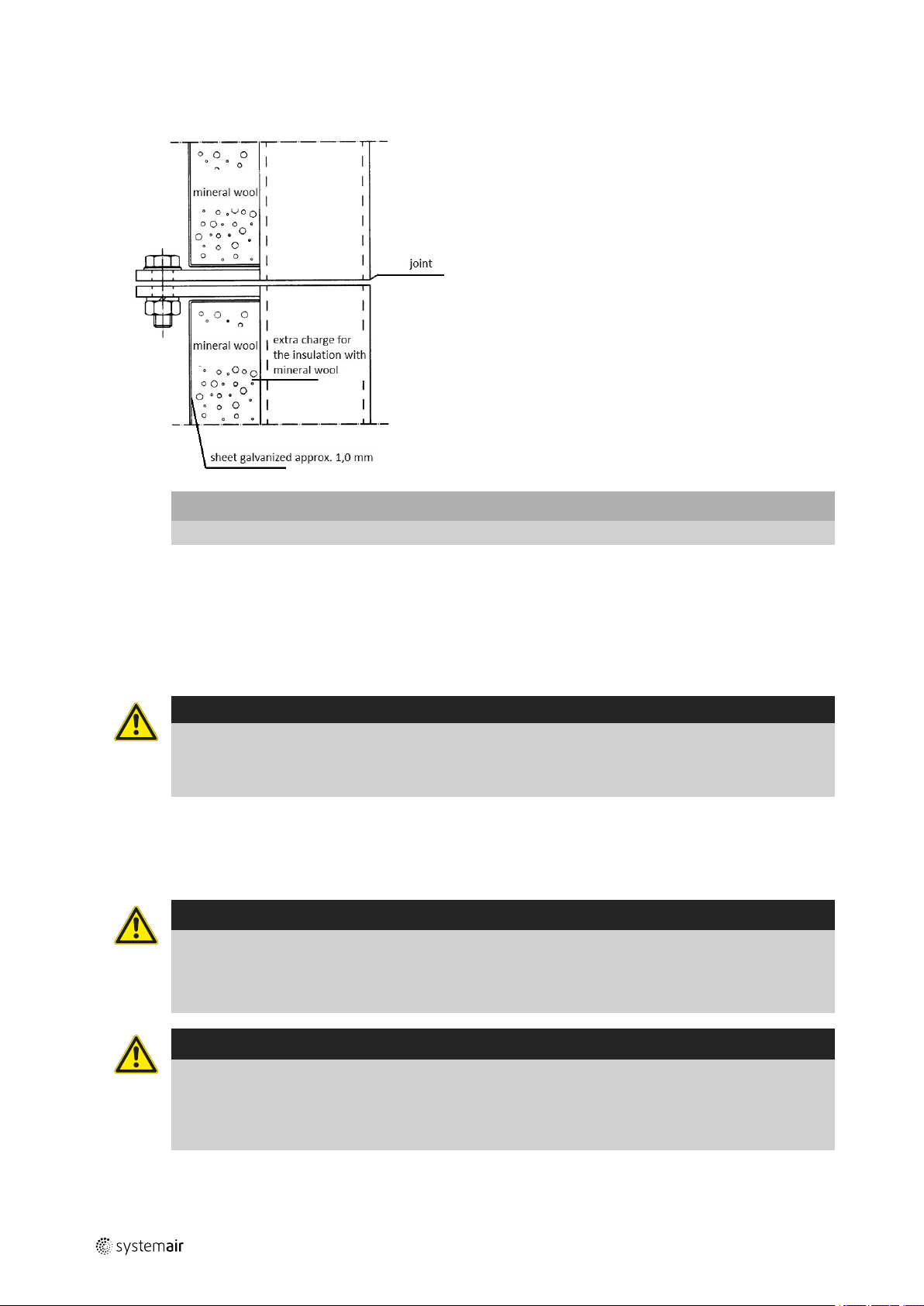
10 Condensation and heat insulation
Outdoor air duct and exhaust ducts must always be well insulated against condensation. Correct insulation installation
on ducts connected to the unit is especially important. All ducts installed in cold rooms/areas must be well insulated.
Use insulating covering (minimum 100 mm mineral wool) with plastic diffusion barrier. In areas with extremely low outdoor temperatures during the winter, additional insulation must be installed. Total insulation thickness must be at least
150 mm.
Caution
• If the unit is installed in a cold place make sure that all joints are covered with insulation, and tape well
• Duct connections/duct ends should be covered during storage and installation
• Do not connect tumble dryers to the ventilation system
11 Maintenance
11.1 Warnings
Danger
• Make sure that the Mains supply to the unit is disconnected before performing any maintenance or
electrical work
• All electrical connections must be carried out by an authorized installer and in accordance with local rules
and regulations
Warning
• Although the Mains supply to the unit has been disconnected there is still risk for injury due to rotating
part that have not come to a complete standstill
• Beware of sharp edges during mounting and maintenance. Use protective clothing
• Beware of hot surface on the heating battery during maintenance and service
|
Page 23

Maintenance
|
11.2 General
The maintenance manual is only for Systemair air handling units of the MAXK-I3 series.
Keep attention to the listed warnings above during maintenance work. Follow the valid general safety requirements
and the valid operating rules. Use suitable and safe ads (ladder, working platform etc.)
Mainly the maintenance work consists of a visual inspection of the air handling unit, periodic filter change and cleaning
of the heat exchanger.
You have to read this instructions before starting maintenance work. Please keep attention to your health during maintenance work. We recommend the use of conventional protection means (breathing protection, disposable gloves etc.).
The specifications of the instructions must be observed. Maintenance shall be performed in accordance with the instructions solely by technical persons qualified for the purpose.
It is recommended to perform maintenance and cleaning by a specialist company periodically.
Please note: if damage is caused due to your failure to observe these instructions, the guarantee is invalidated.
11.3 Maintenance instructions
Performance
Component
1 Fan
1.1
1.2
1.3
1.4
1.5
1.6
2
2.1
2.2
2.3
2.4 Venting
3
3.1
3.2
3.3
3.4
4
4.1
4.2
4.3
4.4 Venting
Air heater (water)
Air heater (electro)
Water cooling battery
Activity
Examine for dirt, damage and corrosion
Function sustenance cleaning of the air
contact parts of the ventilator as well as the
water drain
Check impeller for damage and unbalancing
Check engin mounts for strange noises
Relubrication engin mounts
Check flexible connector for leaks
Check the proper function of the vibration
dampers
Examine for dirt, damage and corrosion
Clean the air heater on air side
Check the proper function of the flow and
return pipes
Check the electrical connection for
corrosion
Function sustenance cleaning (air side)
Check the proper function
Check the function of control- and safety
devices
Examine for dirt, damage and corrosion
Function sustenance cleaning (air side)
Check the proper function of the flow and
return pipes
Periodic If required Number per
year
x
x
x
x
x
x
x
x
x
x
x
x
x
x
x
x
x
x
x
2
1
1
1
1
1
1
4
1
1
2
1
1
2
2
2
19
|
Page 24

20
Maintenance
|
4.5
5 Drop separator
5.1
5.2
5.3
6
6.1
6.2
6.3
6.4
6.5
7
7.1
7.2
7.3
8
8.1
8.2
9 Damper
9.1
9.2
9.3
9.4
9.5
10
10.1
10.2
10.3
10.4
10.5
10.6
11
11.1
11.2
Counterflow heat exchanger
Filter
Weather protection guard
Compartments / unit housing
Air pipes
Check the function of the water drain and
odour seal
examine for dirt, incrustration, damage and
corrosion
Function sustenance cleaning
Check the function of the water drain and
odour seal
Examine for dirt, damage and corrosion
Function sustenance cleaning (air side)
Check the function of the water drain and
odour seal
Check the condensat drip tray for dirt,
corrosion and function
Check the function of the Siphon
Examine for impremissble contamination
and damage (leakage)
Examine differential pressure
Replace filter and document the filter
change
Examine for dirt, mounting, damage and
corrosion
Function sustenance cleaning
Examine for dirt, damage and corrosion
Function sustenance cleaning
Check mechanical function
Relubrication bearing and rod
Check the proper function of the actuator
Function sustenance cleaning
Check the function of the outlets
Clean the outlets
Check the operability and tightness of the
doors and closures
Check the insulation for damage
Clean the inside of the chamber
Check the tightness of the flexible
connectors
Examine accessible air pip sections for
damage, mounting and corrosion
Check the tightness of accessible flexible
connectors
x
x
x
x
x
x
x
x
x
x
x
x
x
x
x
x
x
x
x
x
x
x
x
x
x
x
x
1
1
1
2
1
1
4
4
1
1
1
1
1
1
1
1
1
1
|
Page 25
Disturbances and troubleshooting |
21
11.3
12
12.1
13
13.1
14
14.1
Air passages
Wall grid
Silencer
Examine interior air pipe surface for
contamination and corrosion on two or
more representative place
Examine installed perforated metal plate,
wire mesh of filter for contamination
Examine for dirt and mounting
Examine for dirt, damage and corrosion
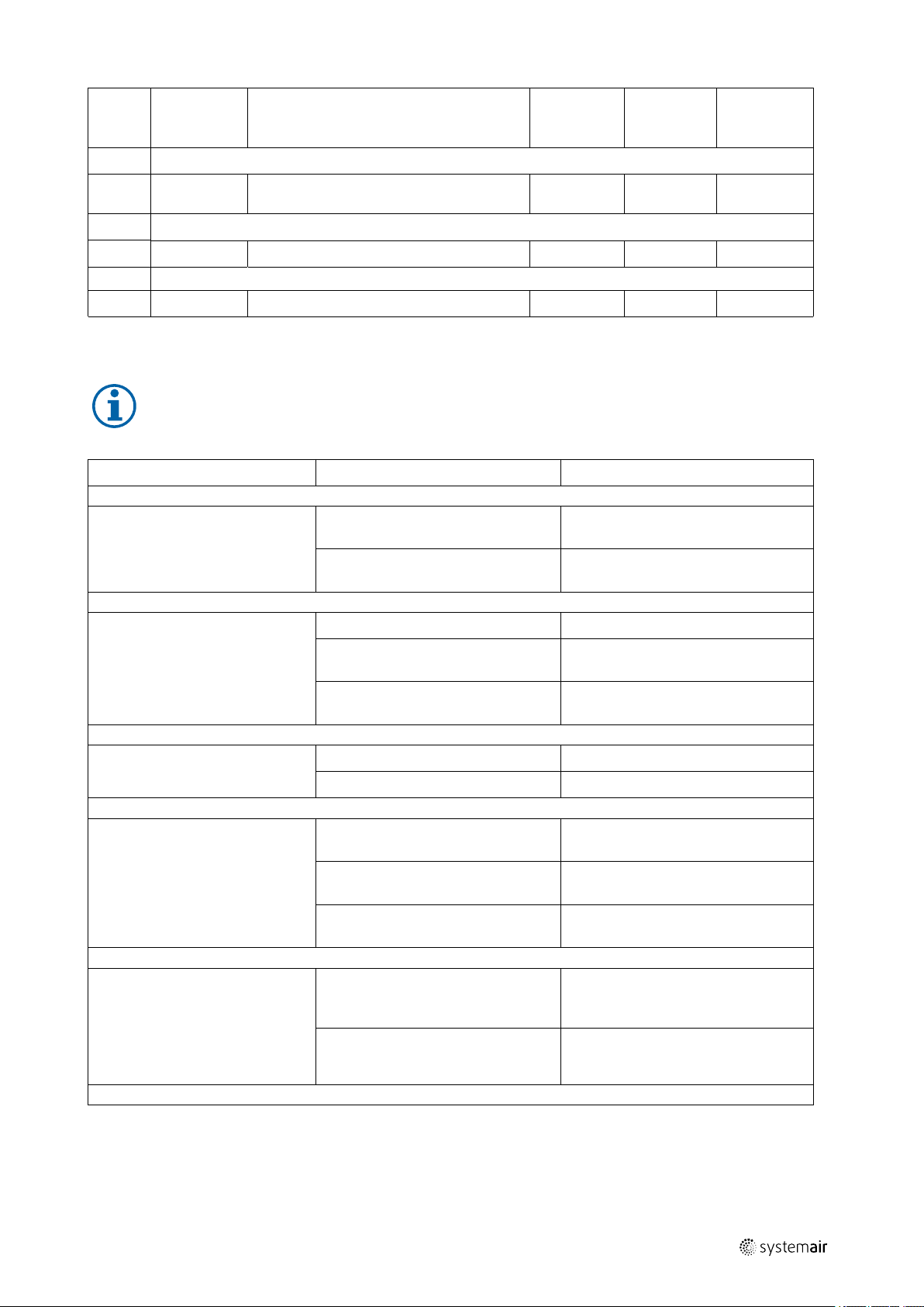
12 Disturbances and troubleshooting
Note:
When error occur first read the table below and follow the instructions. If the error is still not fixed please
contact the customer service
Interruption
The air handling unit is not
working
Potential cause
no electricity supply Connect the air handling unit with the
The connection cables are damaged Disconnect the unit from the power
x
x
x
x
Repair
power supply
supply and contact the manufacturer
1
1
1
Fan running roughly/unsteady Imbalance of the impeller Rebalancing by spcialized company
Wrong direction of rotation of the
impeller
Deformation of the impeller Consultation with the manufacturer.
Air performance to low Pressure drop in the unit to high Check components for dirt
Cloged air passages
Motor does not turn Mechanical blocking Switch off power and remove the
Mains voltage faulty Control the Mains supply, restore
Supply faulty Switch off power, adjust supply, see
Supply air flow to low Filters are polluted Switch off the air handling unit.
Mechanical barriers on the outdoor
air inlet or on the supply air inlet
Consultation with the manufacturer
Install a new impeller.
mechanical blockage
power supply, apply control signal
circuit diagram
Disconnect the unit from the power
supply. Change the filter.
Control the outdoor air inlet and the
supply air inlet. If necessary remove
barriers
|
Page 26

| Disturbances and troubleshooting
22
Air handling unit does not heat or
heats insufficiently
Air handling unit does not cool or
cools insufficiently
Water drops out of the air
handling unit
Air in the water heating battery
To low temperature of the hot water
in the water heating battery
To low power of the heating battery Contact the manufacturer
Heat recovery defect Contact the manufacturer
Air in the water cooling battery
To high temperature of the cooling
coil
To less flow rate of the cooling
medium
To low power of the cooling coil Contact the manufacturer
Damaged or blocked condensation
pipe
Venting
Control the temperature of the heating
medium
Venting
Control the temperature of the cooling
medium
Control the valve. If necessary clean
the valve
Disconnect the unit from the power
outlet. Clean the condensation pipe
incl. syphon
|
Page 27

|
Page 28

Systemair GmbH
Seehöfer Str. 45
97944 Boxberg
Germany
Tel.: +49 (0)7930/9272-0
Fax: +49 (0)7930/9273-92
info@systemair.de
www.systemair.de
MAXK · Installation and Operating Instructions · · en_GB · 2017-06-13 ·
 Loading...