

SystemAir KD-EC 315E, KD-EC 355E, KD-EC 400E, KD-EC 400D, KD-EC 450D Operation And Maintenance Instructions
...Page 1
K EC, KVKE EC, TFSR EC, TFSK EC, KVO EC, KD EC
Operation and maintenance instructions……..…….……………..16
GB
SE
DE
DK
ES
EE
FI
IT
LT
LV
NL
NO
PL
RU
SK
SI
FR
Drift och underhållsinstruktion……………..………………….…..18
Betriebsanleitung..……………..………..………………………….20
Drifts- og vedligeholdelsesvejledning …..…...…………………...23
Instrucciones de uso y mantenimiento.........................................25
Käitamis- ja hooldusjuhised..........................................................27
Käyttö- ja huolto-ohjeet….............................................................29
Istruzioni di funzionamento e manutenzione................................31
Naudojimo ir techninės priežiūros instrukcijos..............................34
Lietošanas un montāžas instrukcija..............................................36
Gebruiks- en onderhoudsinstructies …….………...……………...38
Drifts- og vedlikeholdsanvisning...................................................40
Instrukcja obsługi i konserwacji....................................................42
Руководство по эксплуатации и техническому обслуживани
Pokyny týkajúce sa prevádzky a údržby ………………..….……..47
Navodila za uporabo in vzdreževanje ……. ..…………………….49
Instructions d’utilisation et d’entretien.........................................51
.44
A002
Page 2
r
r
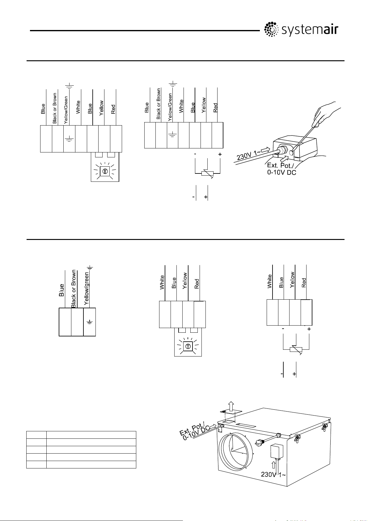
K EC:
230V 1~
L
N
NL 1 2 3 4
Internal potentiometer
KVKE EC:
230V 1~
-
1=Min
0
230V 1~
L
N
K EC
NL 12 34
+
5
10
External potentiometer
Optional
Internal potentiomete
010
10K
0-10V DC
External potentiomete
LN
NL
No. Description
1 Tach output, Isink max 10mA
2 GND
3 Control input 0-10 VDC/PWM
4 Output 10 VDC max 1.1 mA
321 4
010
10K
0-10V DC
-
1=Min
0
321 4
5
10
+
KVKE EC
2
206268 Systemair AB
Page 3
TFSR/TFSK EC:
230V 1~
L
N
NL 1 2 3 4
Internal potentiometer
-
1=Min
0
230V 1~
L
N
NL 12 3 4
+
5
10
External potentiometer
Optional
010
10K
0-10V DC
230 V 1~
Ext. Pot/0-10V DC
3
206268 Systemair AB
Page 4

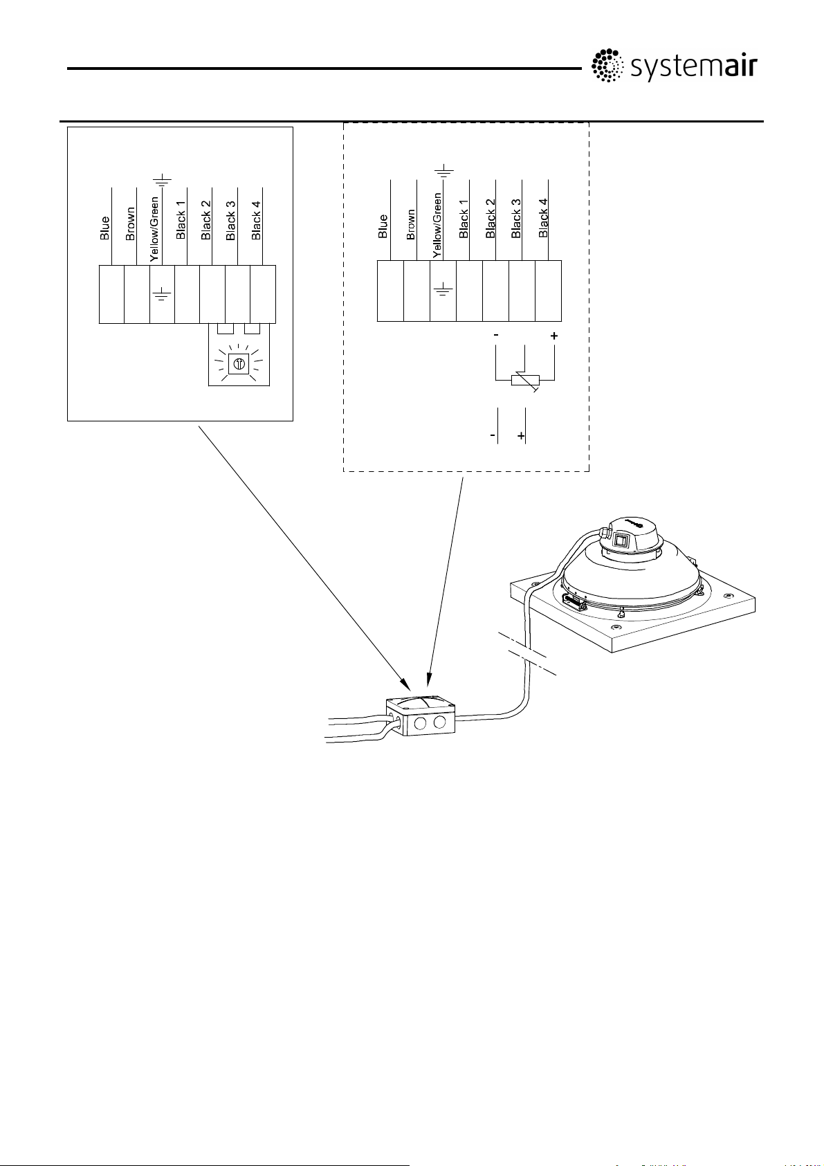
KVO EC:
4
206268 Systemair AB
Page 5
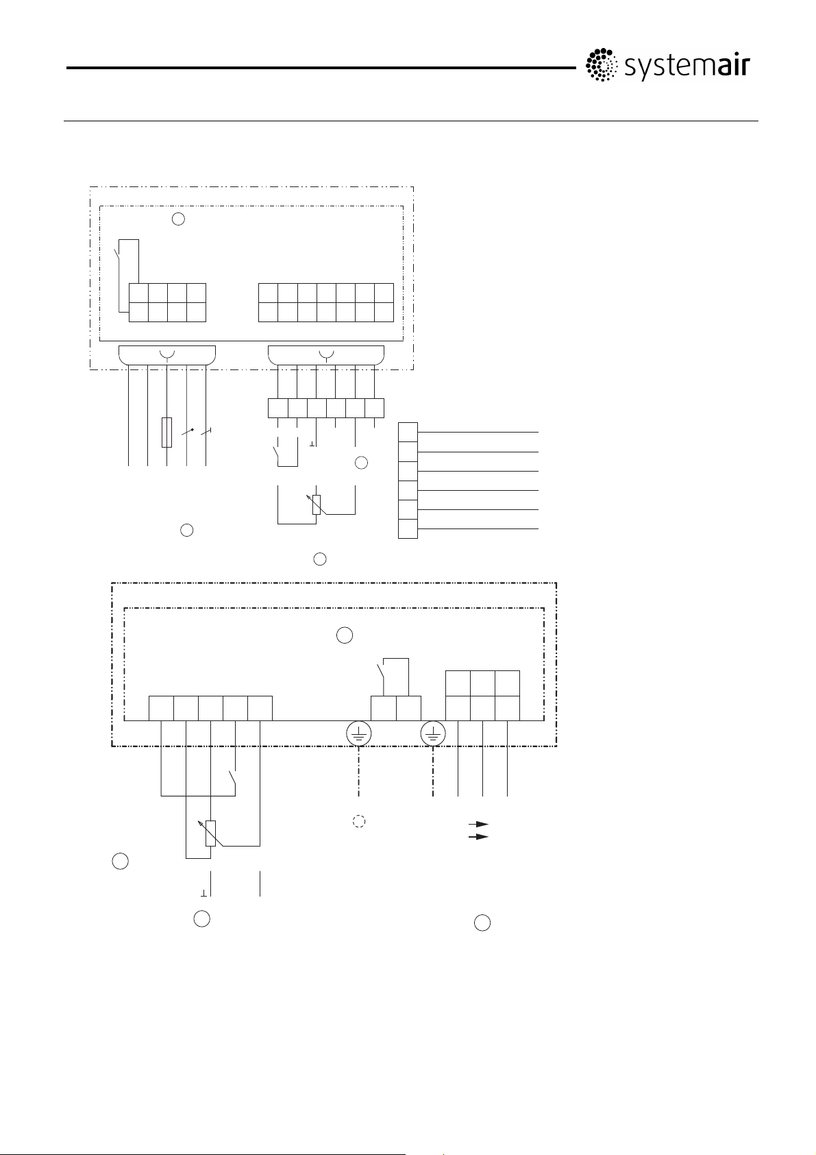
KD EC:
For KD-EC 315E, 355E, 400E
Motor size “B ” (type: _ _ _ _ _-_ I _.B _._ _ _ _)
ECblue Basic
K1
11 - L1 N
14 - - PE
WH
11 14
(_ _ _ _ _-_I_.B_._ _ _ _)
5
Kontaktbelastung
Contact rating
max. AC 250 V 2 A
WH
BU
BN
NL1PE
Netz
Line
1 ~ 200...277 V
50/60 Hz
1
11
A2 GND 10V - - - -
E1 D1 A1 - - - -
GNYE
BU
Eingang
0...10 V
GY
Input
YE
WH
+
4
GN
RD
10V D1GNDA2E1A1
10 kΩ
Internal speed setting
10 V DC Out (I
10V
D1 Digital In 1
D1
GND
GND
A2 Operation Out OC
A2
E1 Analog In 1
E1
A1 Status Out OC
A1
Line voltage 1 ~ 200...277 V, 50/60 Hz
External speed setting
Input 0...10 V
Contact rating max. AC 250 V 2 A
Relay output (K1)
An external fault indicator is available over the potentialfree contact of the built-in relays
(max. contact rating Technical data and connection
diagram).
For operation the relay is energized, connections “11”
and “14” are bridged. For fault the relay is de-energized
(Diagnostics/faults).
When switching off via enable (D1 = Digital In 1), the
relay remains energized.
= 10 mA)
max
RD
GN
BU
GY
YE
WH
For KD-EC 400D, 450D, 500D
ECblue Basic
24V 10V GND D1 E1 11 14
Internal speed setting
3
= 70 mA)
max
DC Out
(I
(_ _ _ _ _-_I_.D_._ _ _ _), (_ _ _ _ _-_I_.G_._ _ _ _)
= 10 mA)
max
(I
DC Out
Digital In 1
10 kΩ
Input
4
0...10 V
Analog In 1
+
3
Kontaktbelastung
2
max. AC 250 V 2 A
PE
Contact rating
L1
L2 L3
L1
K1
Netzspannung Leistungsschild
Line voltage Rating-plate
3 ~ Typ nur in Sonderausführung
für IT-System geeignet
3 ~ type only in special version
suitable for IT-System
1
N
L3/NL2L1PE
Line voltage rating plate (3 ~ type only in special version suitable for IT-System)
Contact rating max. AC 250 V 2 A
External speed setting
Input 0...10 V
5
206268 Systemair AB
Page 6
K EC:
K EC 160
1=Min
5
0
K EC 200
1=Min
5
10
(10,0V)
0 200 400
600
400
[Pa]
200
0
0 0.04 0.08 0.12 0.16
0 200 400 600 800 1000
500
400
300
[Pa]
200
3V
[m³/h]
K EC 160
4V
[m³/s]
[m³/h]
K EC 200
7,5V
8213/8214
10V
7735/7736
0
K EC 250
1=Min
0
Fig 1
10
(10,0V)
100
0
0 0.1 0.2 0.3
0 300 600 900
1000
750
4V 6,5V
[m³/s]
[m³/h]
10V
8V
K EC 250
7791/7792
5
500
[Pa]
10
(10,0V)
250
0
0 0.1 0.2 0.3
2V 3,5V 5V 10V
[m³/s]
6
206268 Systemair AB
Page 7
K EC 315 M
1=Min
5
0
K EC 315 L
1=Min
5
10
(10,0V)
0 400 800 1200
500
400
300
[Pa]
200
100
0
0 0.1 0.2 0.3 0.4
0 500 1000 1500 2000
800
600
400
[Pa]
2,5V 5V 7,3V 10V
[m³/h]
K EC 315 M
[m³/s]
[m³/h]
K EC 315 L
7765/7766
7760/7761
0
10
200
(10,0V)
[m³/s]
5V
7,2V
10V
Fig 2
0
0 0.2 0.4 0.6
3V
7
206268 Systemair AB
Page 8

KVKE EC
KVKE EC 125
1=Min
5
0
10
(10,0V)
KVKE EC 160
1=Min
5
0 100 200 300 400
800
600
400
[Pa]
200
0
0 0.03 0.06 0.09 0.12
0 200 400
600
400
[Pa]
2V
[m³/h]
4,8V
[m³/s]
[m³/h]
KVKE EC 125
7V
KVKE EC 160
8166/8167
10V
7721/7722
0
KVKE EC 200
1=Min
5
0
Fig 3
10
10
(10,0V)
(10,0V)
200
0
0 0.04 0.08 0.12 0.16
0 300 600 900
1000
750
500
[Pa]
250
0
0 0.1 0.2 0.3
4V
6V
[m³/s]
[m³/h]
KVKE EC 200
5V
[m³/s]
7V
10V
8V
7755/7756
10V
8
206268 Systemair AB
Page 9

KVKE EC 250
1=Min
5
0
10
KVKE EC 315
1=Min
5
(10,0V)
0 300 600 900 1200
1000
750
500
[Pa]
250
0
0 0.1 0.2 0.3 0.4
0 500 1000 1500 2000
1000
750
500
[Pa]
2,5V 4,2V
[m³/h]
KVKE EC 250
6V
[m³/s]
[m³/h]
KVKE EC 315
7788/7789
10V
8159/8228
0
10
250
(10,0V)
[m³/s]
6,5V
10V
0
Fig 4
2,5V 4,5V
0 0.2 0.4 0.6
9
206268 Systemair AB
Page 10
TFSR EC/TFSK EC
[m³/h]
TFSR EC/TFSK EC 160
TFSR EC/
TFSK EC 160
1=Min
5
0
10
0 200 400 600
800
600
400
[Pa]
200
(10,0V)
4,9V
[m³/s]
[m³/h]
TFSR EC/TFSK EC 200
TFSR EC/
0
0 0.05 0.1 0.15 0.2
0 200 400 600 800 1000
500
400
2,4V
TFSK EC 200
1=Min
5
300
[Pa]
200
8471/8472
7,2V 10V
8376/8529
0
10
100
(10,0V)
0
0 0.1 0.2 0.3
Fig 5
5V
[m³/s]
7V
6V
10V
10
206268 Systemair AB
Page 11
KVO EC
KVO EC 100
1=Min
5
0
10
(10,0V)
KVO EC 125
1=Min
5
2,1V
[m³/h]
KVO EC 100
4,8V
[m³/s]
[m³/h]
KVO EC 125
0 100 200 300
400
300
200
[Pa]
100
0
0 0.03 0.06 0.09
0 200 400
500
400
300
[Pa]
200
7,3V
11327/11328
10
11340/11341
0
KVO EC 160
1=Min
0
10
(10,0V)
5
10
100
4,5V
0
0 0.04 0.08 0.12 0.16
0 200 400
600
400
[Pa]
200
2,3V
7,3V
[m³/s]
[m³/h]
KVO EC 160
8,2V
10V
11317/11318
(10,0V)
2,5V
0
0 0.04 0.08 0.12 0.16
Fig 6
4V
[m³/s]
6,5V
10V
11
206268 Systemair AB
Page 12
[m³/h]
KVO EC 200
11323/11324
KVO EC 200
1=Min
5
0
10
0 300 600 900
600
400
[Pa]
200
KVO EC 250
1=Min
5
(10,0V)
1,9V
0
0 0.1 0.2 0.3
0 400 800 1200 1600
750
500
[Pa]
3,4V
5V
[m³/s]
[m³/h]
KVO EC 250
10
11338/11339
0
10
250
(10,0V)
0
0 0.2 0.4
KVO EC 315
1=Min
5
0
10
0 500 1000 1500 2000
1000
750
500
[Pa]
250
2,4V 4,3V
6,2V
[m³/s]
[m³/h]
KVO EC 315
10V
11349/11351
(10,0V)
4,3V
0
0 0.2 0.4 0.6
Fig 7
3V
[m³/s]
6,9V
10V
12
206268 Systemair AB
Page 13
0
KD EC
KD EC 315E
1=Min
5
0
10
KD EC 355E
1=Min
5
(10,0V)
0 1000 2000 3000
400
300
200
[Pa]
100
0
0 0.25 0.5 0.75 1
0 1000 2000 3000 4000
300
200
[Pa]
[m³/h]
KD EC 315E
3V 5,5V
[m³/s]
[m³/h]
KD EC 355E
11087/11346
10
8V
11354/11355
100
0
10
(10,0V)
0
0 0.3 0.6 0.9 1.2
0 2000 4000 6000
600
3V
KD EC 400E
400
1=Min
5
[Pa]
200
0
10
5,2V
[m³/s]
[m³/h]
7,2V
KD EC 400E
10V
11360/11388
(10,0V)
0
0 0.5 1 1.5 2
Fig 8
2,8V
5V 7,5V
[m³/s]
1
13
206268 Systemair AB
Page 14

0 3000 6000
1000
KD EC 400D
1=Min
5
0
10
[Pa]
750
500
250
[m³/h]
KD EC 400D
11352/11353
(10,0V)
3V
0
0 1 2 3
KD EC 450D
1=Min
5
0 2500 5000 7500 10000
800
600
400
[Pa]
5,2V 7,2
[m³/s]
[m³/h]
10V
KD EC 450D
11344/11345
0
10
200
(10,0V)
0
0 1 2 3
KD EC 500D
1=Min
5
0
10
0 2500 5000 7500 10000
800
600
400
[Pa]
200
2,9V 5,3V
[m³/s]
[m³/h]
KD EC 500D
7,V5
10V
11358/11359
(10,0V)
[m³/s]
6V
8V 10V
0
0 1 2 3
Fig 9
3,5V
14
206268 Systemair AB
Page 15
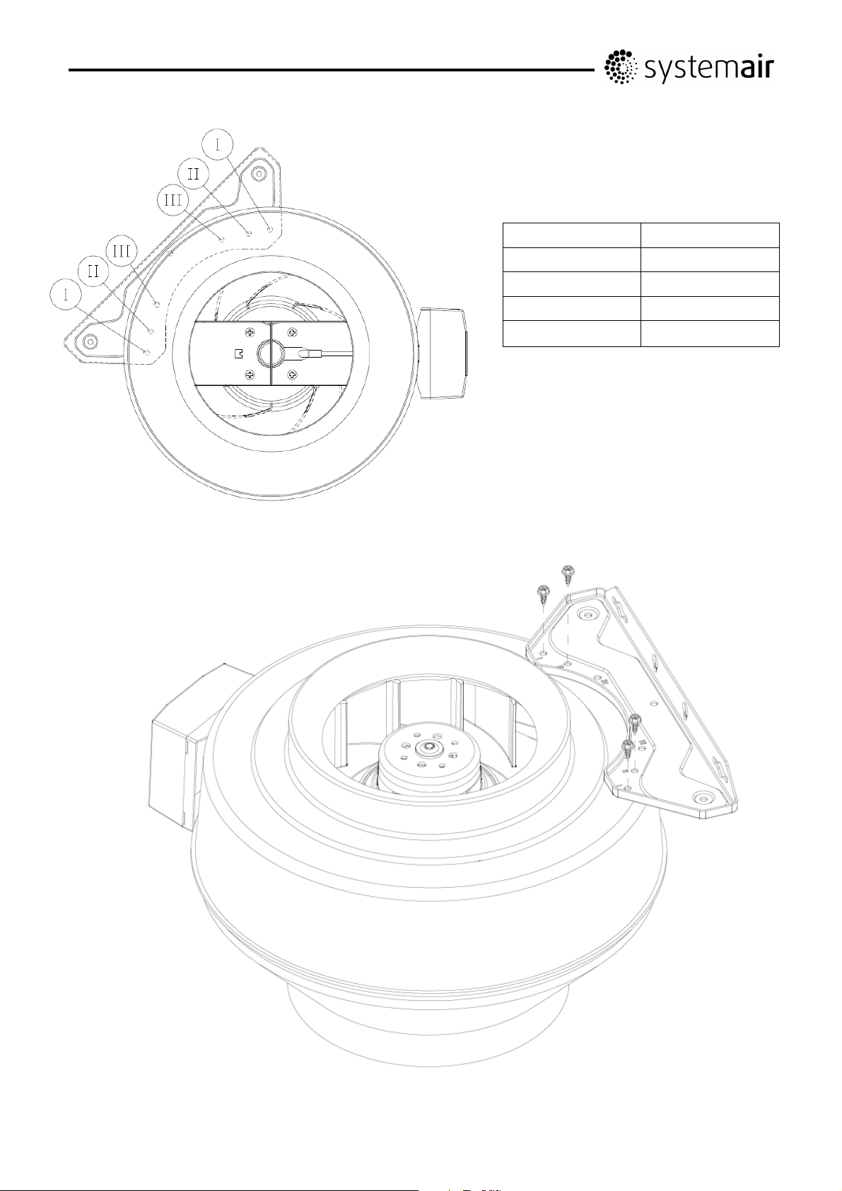
Type Screw
K EC 160 II
K EC 200 I + II
K EC 250 I + II
K EC 315 M/L I + II
15
206268 Systemair AB
Page 16
GB
Declaration of Conformity
Manufacturer
Systemair AB
Industrivägen 3
SE-73930 Skinnskatteberg SWEDEN
Office: +46 222 440 00 Fax: +46 222 440 99
www.systemair.com
hereby confirms that the following products:
Duct fans with circular connection: K EC 160-315L, KVO EC 100-315, KD EC 315-500
Insulated duct fans with circular connection: KVKE EC 125-315
Roof fans with circular or square connection: TFSR EC/TFSK EC 160-200
(The declaration applies only to product in the condition it was delivered in and installed in the facility in
accordance with the included installation instructions. The insurance does not cover components that are added
or actions carried out subsequently on the product)
Comply with all applicable requirements in the following directives
Machinery Directive 2006/42/EC
Low Voltage Directive 2006/95/EC
EMC Directive 2004/108/EC
The following harmonized standards are applied in applicable parts:
EN ISO 12100-1 Safety of machinery – Basic concepts, general principles for design – Part 1: Basic
terminology, methodology
EN ISO 12100-2 Safety of machinery – Basic concepts, general principles for design – Part 2: Technical
principles
EN 14121-1:2007 Safety of machinery – Risk assessment – Part 1: Principles
EN 13857 Safety of machinery – Safety distances to prevent hazard zones being reached by upper or
lower limbs
EN 60 335-1 Household and similar electrical appliances – Safety Part 1: General requirements
EN 60 335-2-80 Household and similar electrical appliances – Safety – Part 2-80: Particular requirements
for fans
EN 50 366-1 Household and similar electrical appliances – Electromagnetic fields – Methods for
evaluations and measurement
EN 50 106:2007 Safety of household and similar appliances – Particular rules for routine tests referring to
appliances under the scope of EN 60 335-1 and EN 60967
EN 60 034-5 Rotating electrical machines – Part 5: Degrees of protection provided by the integral design
of rotating electrical machines (IP code)
EN 60 204-1 Safety of machinery – Electrical equipment of machines – Part 1: General requirements
EN 60730-1 Automatic electrical controls for household and similar use - Part 1: General requirements
EN 61000-6-2 Electromagnetic compatibility (EMC) – Part 6-2: Generic standards – Immunity for industrial
environments
EN 61000-6-3 Electromagnetic compatibility (EMC) – Part 6-3: Generic standards – Emission
standards for residential, commercial and light-industrial environments
Skinnskattberg 15-05-2012
Mats Sándor
Technical Director
Doument in original language
16
Page 17

GB
Safety Information
This machinery must not be put into operation prior to
reading mounting instructions and safety information.
All fans are intended for transportation of air in air handling
systems. If installed in non-heated rooms, fan casing must
be insulated in order to avoid condensation. They are
designed to be used once built into machines or ducted to
be used into machines or duct systems or after contact
protection grid has been installed. (EN ISO 13857). Fans
with duct connections must be connected to ducts on both
sides (inlet/outlet). Should there be a risk of water entering
the motor, via the ducts, external protection is required. No
moving parts shall be accessible after installation. The fans
are not to be used in hazardous environments or connected
to flue ducts. The fans must not be installed outdoors
(except TFSR/TFSK EC, K EC ). Safety accessories (i.e.
safety grille) may not be dismounted, short cut or
disconnected. CAUTION Before servicing or maintenance,
switch off power, (all-pole circuit breaker), and make sure
the impeller has come a standstill. CAUTION the fans can
have sharp edges and corners which may cause injuries.
CAUTION be careful when opening the fans service-hatches
(swing-out), the fan and motor assembled on the hatch is
relatively heavy (applies to KVKE, KVO).
The fan motor has built in protection for locked rotor, which
implies that the motor tries to restart with a preprogrammed
interval whenever it senses that the rotor is standing still.
When the blockage is removed the fan will start up by itself
without any further measures. At high motor temperatures
the current will be cut from the motor. It can then only be
restarted by manually disconnecting the mains supply to the
fan for couple of minutes.
Transportation and Storage
All fans are packaged at the factory to withstand normal
transport handling. When handling the goods use suitable
lifting equipment in order to avoid damage to fans and
personnel. Do not lift the fans by the connecting cable,
connection box, impeller or inlet cone. Avoid blows and
shock loads. Store the fans in a dry place protected from
weather and dirt until final installation. Permissible storage
temperatures -40…+80°C
Installation
Refer to Safety information above. Installation, electrical
connection and commissioning are only to be carried out by
authorised personnel and in accordance with requirements
and demands. Electrical connection according to the wiring
diagram in the terminal box, markings on terminal blocks or
on cable. CAUTION do not use metal compression gland
fittings with plastic terminal boxes. Use a dummy plug seal
for the compression gland fitting as well. The K-EC fan must
be installed with the connection box at the top of the unit ±
90 degrees. If permanent installation is carried out using
cables with diameter 12-14 mm, the electrical gland must be
replaced (applies to type K-EC). Assemble the fan in the
direction of airflow (see arrow on unit). The fan must be
installed so that vibration is not transmitted via ducted
systems or building structure. (Suitable accessories such as
fast clamps and diffusers are available). Make sure the
assembly of the fan is firm and stable. The fan can be
mounted in any direction unless stated otherwise. The fans
must be assembled so that service and maintenance can be
performed easily and safely. Disturbing noise can be
avoided by installing silencers (available accessory).
The fans are meant for continuous use within the
temperature range stated.
For fans which reset by cutting the current, must be taken
into consideration when connecting surrounding equipment
with automatic on/off function.
EC motors have a leakage current to earth corresponding to
<=3,5 mA. This needs to be considered whenever the fan is
connected together with an earth fault breaker.
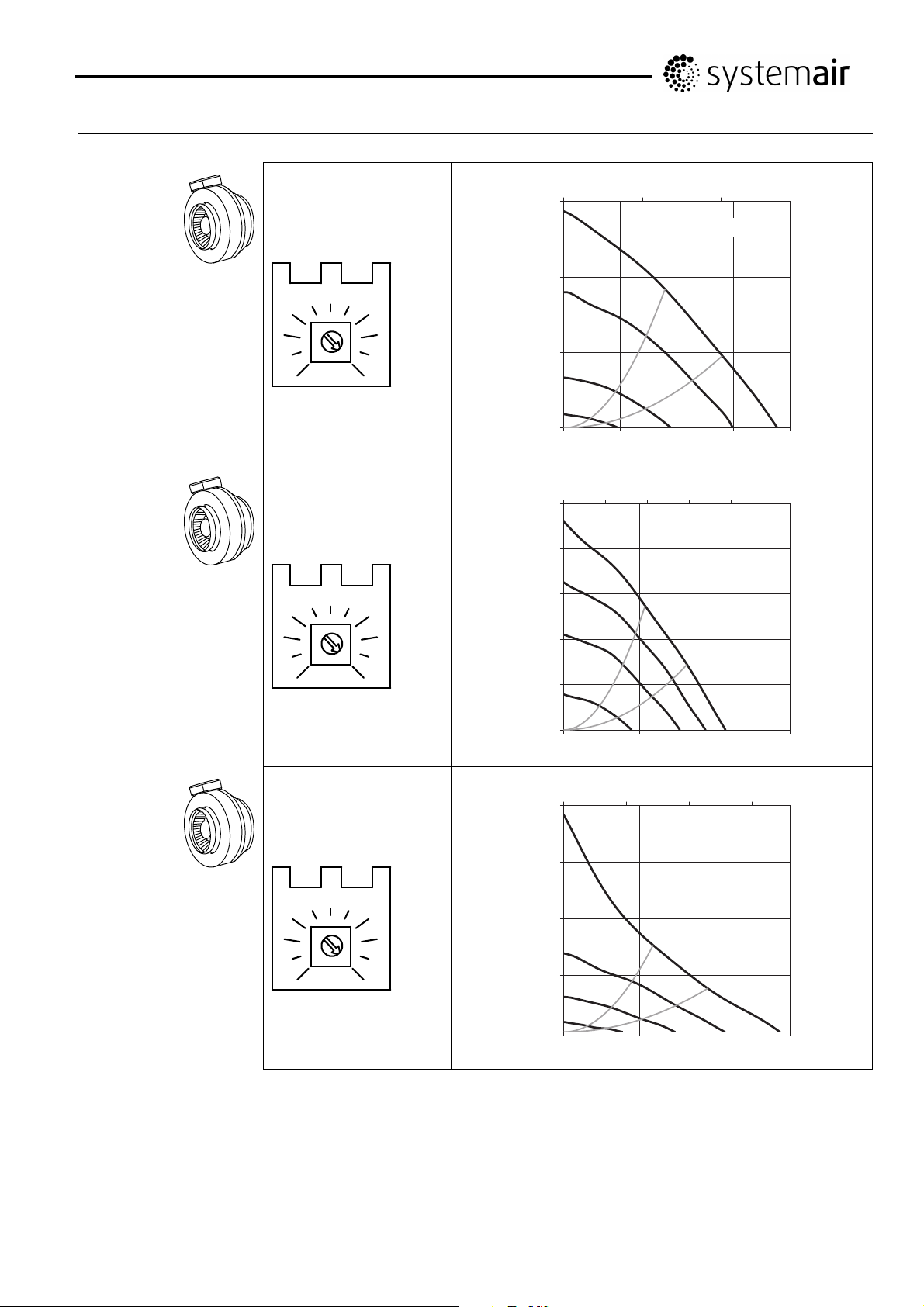
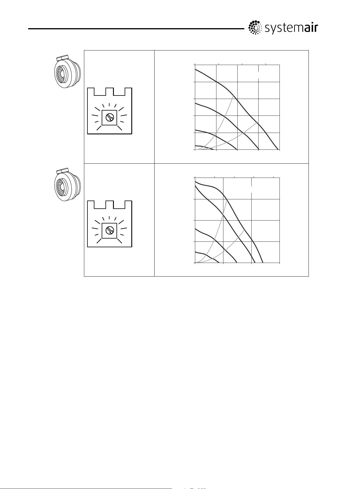
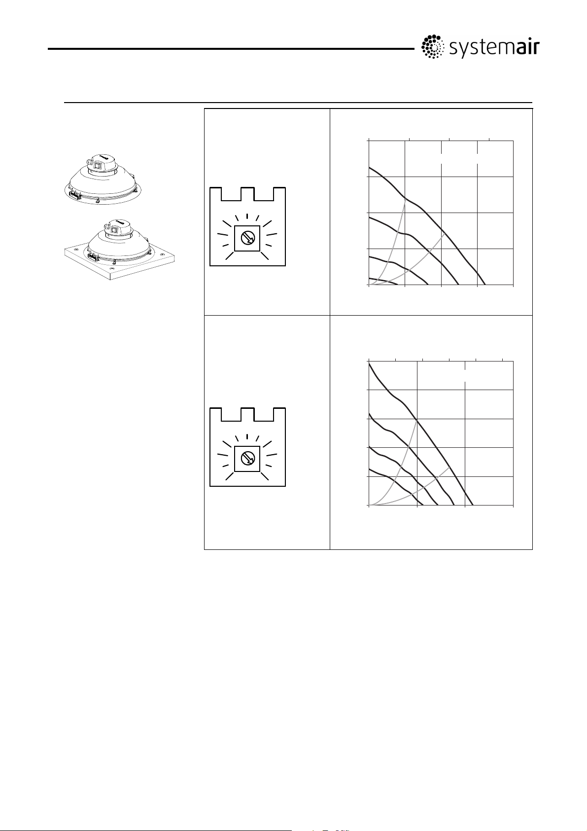
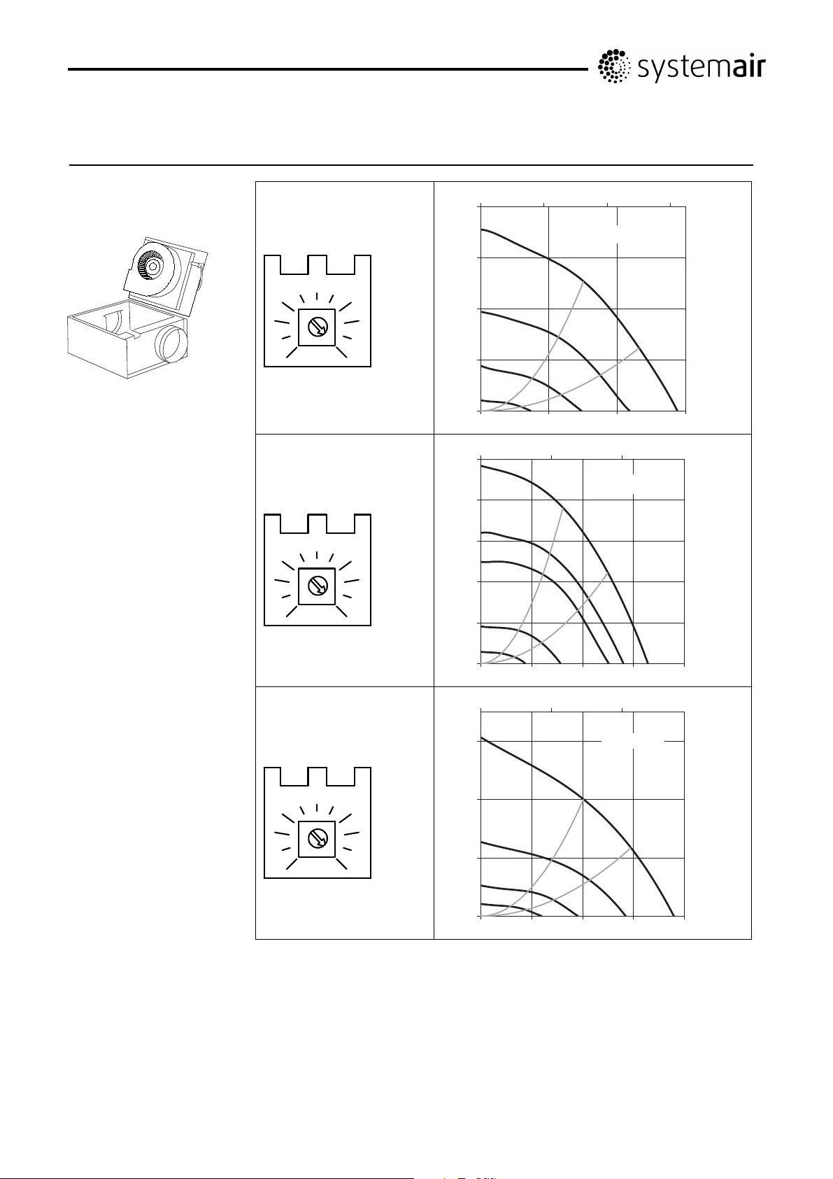
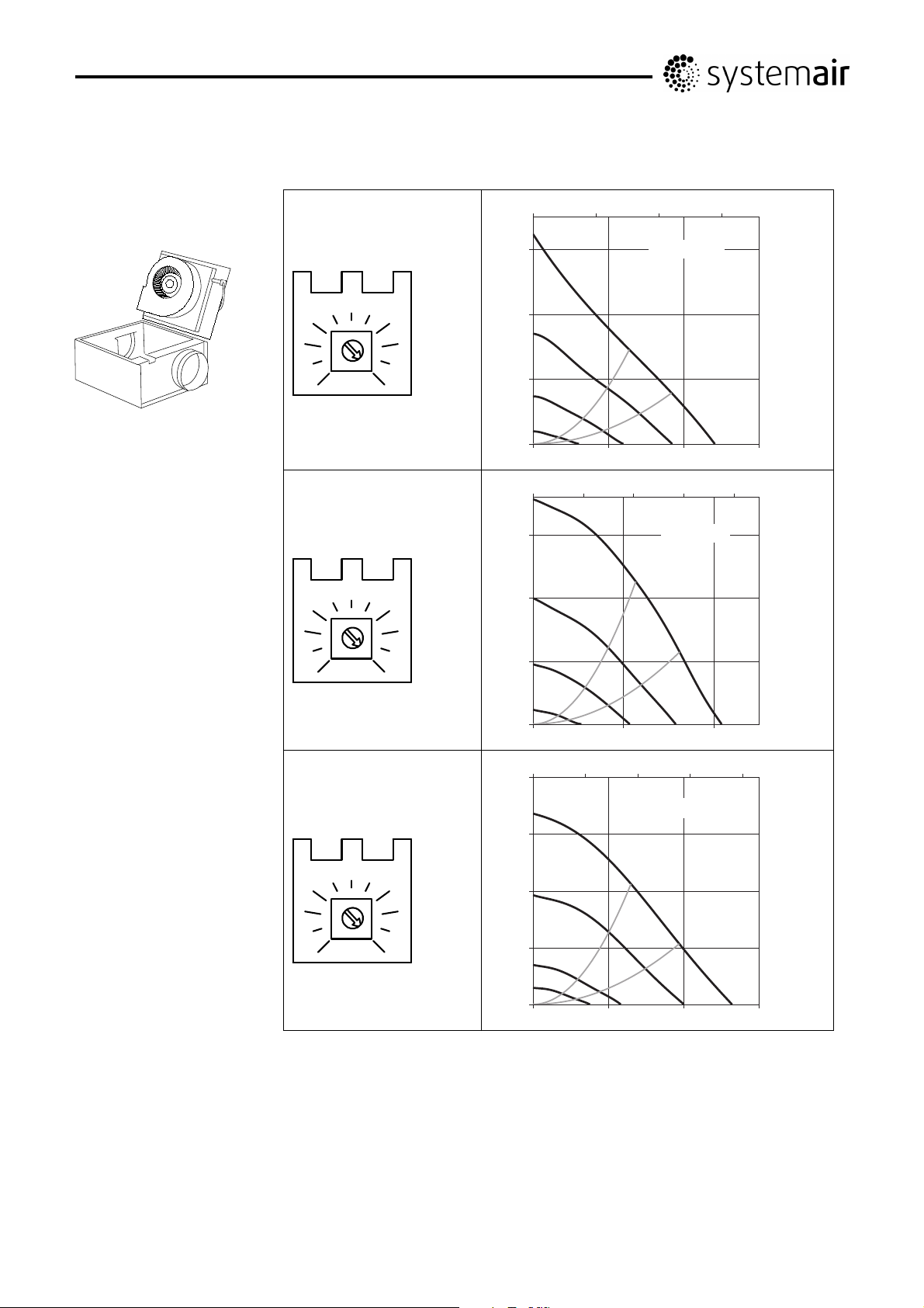
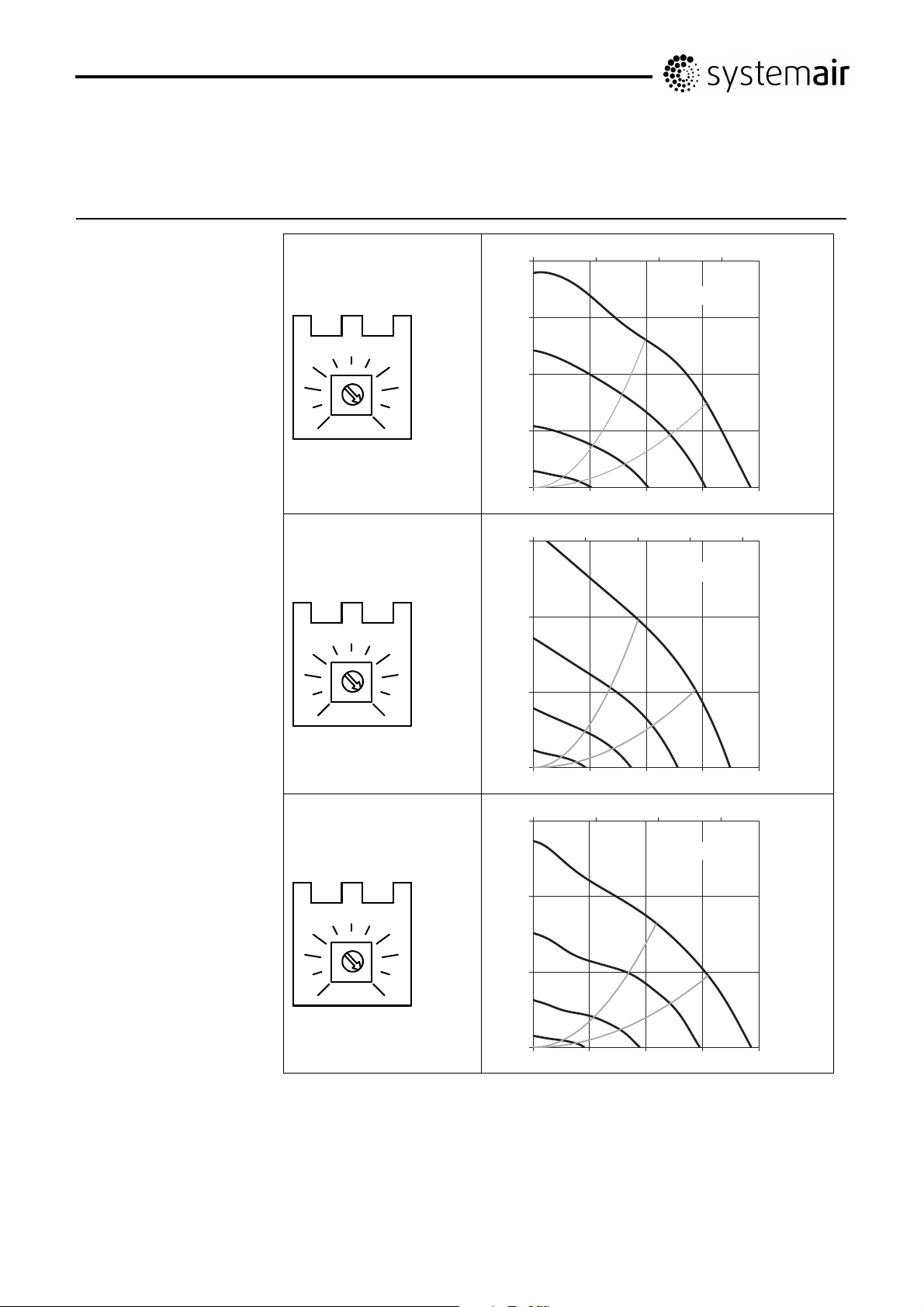
Integral potentiometer
The integral potentiometer is factory preset (Fig. 1-9). This
value can be changed manually to obtain a different motor
rpm/fan performance. Fan preformance charts for this
purpose are shown in the table by voltage steps on page 513 (Fig. 1-9) to the right of the pot. symbols. An external
potentiometer can be connected if necessary. If so the
internal potentiometer needs to be disconnected from the
connection terminals.
Tach output
Terminal No. 1 in the wiring diagrams (white signal cable)
enables connection of an rpm counter (one pulse per
revolution), controller, alarm or a speed display. The Tacho
a signal with max 10mA.
Operation
Before initial operation, check the following:
- Electrical connection has been properly completed.
- Protective conductor has been connected.
- Safety devices in place (protection grid)
- Leftover installation materials and foreign materials have
been removed from the casing.
When putting into operation, check the following:
- Connection data corresponds to the specifications on the
nameplate: Maximum voltage +6%, -10%, according to IEC
38. Rated current must not be exceeded with more than 5%
at rated voltage.
- Smoothness of motor operation, (no abnormal noises).
-Fans must only be operated by a person which has suitable
knowledge or education within this field or carried out with
the supervision of a suitably qualified person.
Maintenance, Service and Repair
Prior to maintenance, service or repair make sure that:
- Power supply is interrupted (all-pole circuit breaker).
- Fan impeller has come to a complete standstill
- Observe personnel safety regulations!
The fan should be cleaned when necessary, at least 1/year
to avoid imbalance and unnecessary damage to the
bearings. A filter will further improve the time interval
between cleaning of the fan. (It is sometimes recommended
to install a filter guard). The fan bearings are maintenance
free and should only be replaced if damaged. Do not use a
high-pressure cleaner (steam jet) when cleaning the fan.
Make sure the fan impeller's balance weights are not moved
or the fan impeller distorted. Listen for abnormal operating
noise.
The following applies in case the fan has stopped:
- Try to restart the fan by cutting the power a couple of
minutes.
- Ensure that the impeller is not locked. Possible obstruction
to be removed after the current has been switched off.
Check that the fan starts after reconnecting the current.
Should the fan not start please contact your place of
purchase.
Doument in original language
17
Page 18

SE
Försäkran om överensstämmelse
Tillverkare
Systemair AB
Industrivägen 3
SE-73930 Skinnskatteberg SVERIGE
Kontor: +46 222 440 00 Fax: +46 222 440 99
www.systemair.com
intygar härmed att följande produkter:
Kanalfläktar med cirkulär anslutning: K EC 160-315L, KVO EC 100-315, KD EC 315-500
Isolerade kanalfläktar med cirkulär anslutning: KVKE EC 125-315
Takfläktar med cirkulär eller rektangulär anslutning: TFSR EC/TFSK EC 160-200
( Intyget gäller endast för produkten i det skick i vilket den levererats och installerats vid anläggningen i enlighet
med medföljande installationsanvisningar. Intyget omfattar inte komponenter som senare lagts till eller åtgärder
som senare vidtagits på produkten.)
uppfyller alla tillämpliga krav i nedanstående direktiv.
Maskindirektivet 2006/42/EG
Lågspänningsdirektivet 2006/95/EG
EMC-direktivet 2004/108/EG
Tillämpliga delar av nedanstående harmoniserade standarder tillämpas.
EN ISO 12100-1 Maskinsäkerhet – Grundläggande begrepp, allmänna konstruktionsprinciper – Del 1:
Grundläggande terminologi, metodik
EN ISO 12100-2 Maskinsäkerhet – Grundläggande begrepp, allmänna konstruktionsprinciper – Del 2:
Tekniska principer
EN 14121-1:2007 Maskinsäkerhet – Riskbedömning – Del 1: Principer
EN 13857 Maskinsäkerhet – Skyddsavstånd för att hindra att armar och ben når in i riskområden
EN 60335-1 Elektriska hushållsapparater och liknande bruksföremål – Säkerhet – Del 1: Allmänna
fordringar
EN 60335-2-80 Elektriska hushållsapparater och liknande bruksföremål – Säkerhet – Del 2-80: Särskilda
fordringar på fläktar
EN 50366-1 Hushållsapparater och liknande bruksföremål – Mätning och bestämning av
elektromagnetiska fält
EN 50106:2007 Elektriska hushållsapparater och liknande bruksföremål – Säkerhet – Anvisningar för
tillverkningskontroll av apparater som omfattas av EN 60335-1 och EN 60967
EN 60034-5 Roterande elektriska maskiner – Del 5: Kapslingsklasser för elektriska maskiner (IP beteckning)
EN 60204-1 Maskinsäkerhet – Maskiners elutrustning – Del 1: Allmänna fordringar
EN 60730-1 Automatiska elektriska styr- och reglerdon för hushållsbruk – Del 1: Allmänna fordringar
EN 61000-6-2 Elektromagnetisk kompatibilitet (EMC) – Del 6-2: Generella fordringar – Immunitet hos
utrustning i industrimiljö
EN 61000-6-3 Elektromagnetisk kompatibilitet (EMC) – Del 6-3: Generella fordringar – Emission från
utrustning i bostäder, kontor, butiker och liknande miljöer
Skinnskatteberg 2012-05-15
Mats Sándor
Teknisk Direktör
Dokument översatt från engelska
18
Page 19

SE
Säkerhet
Fläktar får ej tas i bruk innan installationsanvisning och
säkerhetsanvisning har beaktats.
Fläktar för ventilation i luftbehandlingssystem med luft från
icke explosionsfarligt utrymme. Vid montering i ouppvärmda
utrymmen skall fläkten isoleras så att kondensutfällning
undviks. Fläktar är produkter som är avsedda att tas i bruk
endast efter inbyggnad, kanalanslutning eller att produkten
försetts med beröringsskydd. (EN ISO 13857). På fläktar
som har kanalanslutningar ska kanaler monteras på sug/tryck-sida, när risk finns för att vatten via kanaler kan
tränga in i motorn så måste någon form av externt skydd
monteras på kanaler. Efter Installation/kanalanslutning ska
beröring av rörliga delar ej vara möjlig. Fläktarna får ej
användas i explosiv miljö eller anslutas till rökgaskanal.
Fläktarna får ej monteras utomhus (gäller ej TFSR/TFSK
EC, K EC). Säkerhetsdetaljer (t.ex. beröringsskydd) får ej
demonteras. OBS! Innan service och underhåll påbörjas
måste fläktarna göras spänningslösa, allpolig brytning, och
fläkthjulet ha stannat. OBS! Fläktarna kan ha vassa kanter
och hörn, vilket kan orsaka skärskador. OBS! Iaktag
försiktighet vid öppnande av fläktarnas serviceluckor, då
fläkt med motor monterad på serviceluckan kan vara relativt
tung.
Fläktmotorn har ett inbyggt skydd för låst rotor, vilket
innebär att motorn, när den känner att rotorn står still
försöker starta igen med ett förprogrammerat intervall. När
blockeringen har avlägsnats startar motorn av sig själv utan
vidare åtgärd. Vid höga temperaturer i motorn kommer
strömmen till motorn att brytas. Fläkten kan då endast
återstartas efter att den gjorts spänningslös under några
minuter.
Transport och lagring
Samtliga fläktar som levereras från Systemair är
emballerade för att klara normal godshantering. Vid
godshantering använd lämplig lyftanordning för att undvika
skador på fläktar och personer. OBS! Lyft ej fläktarna i
motorkabel, kopplingsdosa, fläkthjul eller insugningskona.
Undvik slag och stötar. Fläktarna ska lagras torrt och
väderskyddat och skyddas från smuts och damm före slutlig
installation. Tillåtna lagringstemperaturer: -40…+80°C
Installation
Se även avsnitt säkerhet. Installation, elektrisk anslutning
samt idrifttagande ska göras av behörig installatör och
utföras i enlighet med för installationen gällande föreskrifter
och krav. Elektrisk anslutning ska göras enligt kopplingsscheman i kopplingsdosa, märkning på kopplingsplint eller
på kabel. OBS! Använd ej förskruvningar av metall om
kopplingsdosan är av plast. Täta ev. tomma
förskruvningshål med blindplugg. Anslutningsdosa ska på
K-EC fläktar monteras i en position rakt upp ± 90 grader.
Om fast installation sker med kabel som har diam. 1214mm så måste införings-bussningen bytas, gäller typ KEC. Montera fläkten i rätt luftriktning (se luftriktningspil).
Fläkten ska monteras så att vibrationer ej kan överföras till
kanalsystem och byggnadsstomme. (För ändamålet finns
fästklammer som tillbehör). Fläktar kan monteras i valfritt
inbyggnadsläge om annat ej anges. Fläkten ska monteras
på ett stadigt och stabilt sätt. Fläkten ska monteras så att
service och underhåll kan utföras på ett enkelt och säkert
sätt. Ljudproblem kan förebyggas genom installation av
ljuddämpare (finns som tillbehör). Fläktar är avsedda för
kontinuerlig drift inom angivna temperaturområden.
För kopplingschema gäller följande färger på signalkablar:
White = Vit, Red = Röd, Yellow = Gul, Blue = Blå.
För matningskablar gäller:
Black = Svart, Blue = Blå, Yellow/green = Gul/grön.
För fläktar som återställs genom att göra fläkten
spänningslös så måste detta beaktas vid inkoppling av
kringutrustning som bryter och kopplar in strömmen
automatiskt.
EC motorer har en läckström till jord på <=3,5 mA. Detta
ska beaktas vid installation tillsammans med jordfelsbrytare.
Inbyggd potentiometer
Den inbyggda potentiometern är förinställd från fabrik
(Fig. 1-9). Detta värde går att ändra manuellt för att få
annat rpm/luftflöde. Se fläktdiagram för detta ändamål i
tabellen på sid. 5-13 (Fig. 1-9) med inkluderade
spänningssteg till höger om potentiometersymbolerna. En
extern potentiometer kan anslutas till plint vid behov. Den
interna potentiometern skall då kopplas bort från plint.
Tacometerutgång (Tach output)
Plint nr. 1 i ovan anslutningssheman (vit signal kabel),
möjliggör inkoppling av varvräknare (en puls per rotation),
extern styrning, larm, eller varvtalsdisplay. Tacometern
sänker en signal med max 10mA.
Drift
Före idrifttagande kontrollera följande:
-Elektrisk anslutning är slutförd.
-Skyddsjorden ansluten.
-Säkerhetsutrustning monterad (beröringsskydd).
-Inga främmande föremål finns i fläkten.
Vid idrifttagande kontrollera följande:
Att uppmätta data ej överstiger på fläktens typskylt angivna
märkdata: Maximalt tillåten spänning +6%, -10 %, enligt IEC
38. Märkströmmen får ej överskridas med mer än 5 % vid
märkspänning.
-Att inga missljud hörs från fläkten.
-Fläktar i drift får endast handhas av person som har
kunskap eller utbildning för detta, eller att handhavande
sker under överinseende av sådan person.
Underhåll, service och reparation
Innan service, underhåll eller reparation påbörjas måste:
-Fläkten göras spänningslös (allpolig brytning).
-Fläkthjulet stannat.
-Gällande säkerhetsföreskrifter beaktats.
Fläkten ska rengöras vid behov, dock minst 1 gång/år för att
undvika obalans med onödiga lagerskador som följd. Med
ett filter monterat före fläkten kan rengöringsintervallet
förlängas. (Användande av andningsskydd vid byte av filter
rekommenderas). Fläktens lager är underhållsfria och ska
endast bytas vid behov. Vid rengöring av fläkten får
högtryckstvätt ej användas. Rengöring måste ske försiktigt
så att fläkthjulets balansvikter ej rubbas eller fläkthjulet
deformeras. Kontrollera att inga missljud hörs från fläkten.
Om fläkten har stannat gäller följande:
- Prova att återstarta genom att göra fläkten spänningslös
under några minuter.
- Kontrollera att fläkthjulet inte är blockerat. Ev. blockering
avlägsnas efter att strömmen brutits. Kontrollera att fläkten
startar när strömmen kopplas åter. Om fläkten efter kontroll
och/eller återställning inte startar, kontakta ert inköpsställe.
Dokument översatt från engelska
19
Page 20

DE
Konformitätserklärung
Hersteller
Systemair AB
Industrivägen 3
SE-73930 Skinnskatteberg SCHWEDEN
Büro: +46 222 440 00 Fax: +46 222 440 99
www.systemair.com
bestätigt hiermit, dass die folgenden Produkte:
Rohrventilatoren mit Rundverbindung: K EC 160-315L, KVO EC 100-315, KD EC 315-500
Schallgedämmte Rohrventilatoren mit Rundverbindung: KVKE EC 125-315
Dachventilatoren mit Rund- oder rechteckiger Verbindung: TFSR EC/TFSK EC 160-200
(Die Erklärung gilt nur für diese Produkte, wenn sie in die Einrichtung geliefert und dort gemäß den
dazugehörigen Installationsanweisungen installiert wurden. Die Versicherung deckt keine Komponenten ab, die
hinzugefügt wurden, oder Handlungen, die nachfolgend am Produkt vorgenommen wurden.)
Mit allen geltenden Anforderungen der folgenden Richtlinien im Einklang stehen
Maschinenrichtlinie 2006/42/EG
Niederspannungsrichtlinie 2006/95/EG
EMV-Richtlinie 2004/108/EG
Die folgenden harmonisierten Normen gelten für die entsprechenden Teile:
EN ISO 12100-1 Sicherheit von Maschinen - Grundbegriffe, allgemeine Gestaltungsleitsätze - Teil 1
Grundsätzliche Terminologie, Methodologie
EN ISO 12100-2 Sicherheit von Maschinen - Grundbegriffe, allgemeine Gestaltungsleitsätze - Teil 2
Technische Leitsätze
EN 14121-1:2007 Sicherheit von Maschinen - Risikobeurteilung - Teil 1 Leitsätze
EN 13857 Sicherheit von Maschinen - Sicherheitsabstände gegen das Erreichen von
Gefährdungsbereichen mit den oberen oder unteren Gliedmaßen
EN 60.335-1 Elektrische Geräte für den Hausgebrauch und ähnliche Zwecke - Sicherheit Teil 1:
Allgemeine Anforderungen
EN 60.335-2-80 Elektrische Geräte für den Hausgebrauch und ähnliche Zwecke - Sicherheit - Teil 2-80:
Besondere Anforderungen für Ventilatoren
EN 50.366-1 Elektrische Geräte für den Hausgebrauch und ähnliche Zwecke - Elektromagnetische Felder
- Methoden für Auswertungen und zur Messung
EN 50 106:2007 Sicherheit elektrischer Geräte für den Hausgebrauch und ähnliche Zwecke - Besondere
Regeln für Stückprüfungen von Geräten im Anwendungsbereich der EN 60 335-1 und EN 60967
EN 60.034-5 Drehende elektrische Maschinen - Teil 5: Schutzarten aufgrund der Gesamtkonstruktion von
drehenden elektrischen Maschinen (IP Code)
EN 60.204-1 Sicherheit von Maschinen - Elektrische Ausrüstung von Maschinen - Teil 1: Allgemeine
Anforderungen
EN 60730-1 Automatische elektrische Regel- und Steuergeräte für den Hausgebrauch und ähnliche
Anwendungen - Teil 1: Allgemeine Anforderungen
EN 61000-6-2 Elektromagnetische Verträglichkeit (EMV) - Teil 6-2: Fachgrundnorm - Störfestigkeit für
Industriebereiche
EN 61000-6-3 Elektromagnetische Verträglichkeit (EMV) - Teil 6-3: Fachgrundnorm - Störaussendung
Fachgrundnorm für Wohnbereich, Geschäfts- und Gewerbebereich sowie Kleinbetriebe
Skinnskattberg 15.05.2012
Mats Sándor
Technischer Direktor
Aus dem Englischen übersetztes Dokument
20
Page 21
DE
Sicherheitshinweise
Diese Maschinen dürfen nur in Betrieb genommen werden,
wenn zuvor die Montage-, Betriebsanleitung und die
Sicherheitsvorschriften gelesen wurden. Alle Ventilatoren
sind zur Förderung von Luft in Lüftungssystemen geeignet.
Um Kondensation zu vermeiden sollten Ventilatoren die in
unbeheizten Räumen installiert sind, zusätzlich isoliert
werden. Der Betrieb der Ventilatoren ist erst nach erfolgtem
Einbau in Maschinen oder Kanalsysteme oder nach dem
Einbau eines Berührungsschutzgitters vorgesehen (EN ISO
13857). Ventilatoren mit Kanalanschluss müssen an beiden
Seiten (Zu-/Abluft) an die Kanäle angeschlossen werden. Um
das Eindringen von Wasser aus den Kanälen in den Motor zu
verhindern, ist eine außenliegende Schutzvorrichtung
notwendig. Nach dem Einbau sollten keine beweglichen Teile
mehr zugänglich sein. Die Ventilatoren dürfen nicht in
gefährlichen Bereichen betrieben und nicht an Flüssigkeit
leitende Kanäle angeschlossen werden. Die Ventilatoren
dürfen nicht im Freien angebracht werden (auser TFSR/TFSK
EC, K EC). Sicherheitszubehör (z.B. Schutzgitter) dürfen
nicht entfernt werden. ACHTUNG! Vor Wartungsarbeiten
muss die Stromzufuhr abgestellt werden (allpolige
Stromunterbrechung; Absicherung gegen unbeabsichtigtes
Wiedereinschalten). Das Laufrad muss beim Öffnen absolut
stillstehen, ansonsten besteht Verletzungsgefahr. ACHTUNG!
Die Ventilatoren können scharfe Kanten oder Ecken haben,
es besteht Verletzungsgefahr. ACHTUNG ! Die
Wartungstüren (bei aufklappbaren Ventilatoren) nur vorsichtig
öffnen, da das Motorlüfterrad, welches auf der Tür montiert
ist, sehr schwer sein kann. Der Ventilatormotor ist mit ein
Schutz für blockierten Rotor augerüstet. Der Motor versucht
mit einen vorprogrammierten Intervall den Rotor wieder
anzulaufen. Das widerholt sich biss die Blockierung entfernt
ist, danach startet der Motor von allein wider auf. Bei hohen
Temperaturen wird die Stromversorgung des motors
unterbrochen. Der Ventilator kann dan nur wieder gestartet
werden nachdem er ein paar Minuten spannungslos gemacht
wird.
Transport und Lagerung
Alle Ventilatoren sind werksseitig so verpackt, dass sie gegen
normale Transportbelastungen geschützt sind. Verwenden
Sie geeignetes Hebematerial beim Transport der Geräte, um
Schäden an Personen oder Material zu vermeiden.
Transportieren Sie die Geräte nicht am Anschlusskabel, am
Klemmkasten, am Laufrad oder an der Einströmdüse.
Vermeiden Sie Belastungen durch Schläge und Stöße.
Lagern Sie die Ventilatoren bis zur endgültigen Installation an
einem trockenen, wetter- und staubgeschützten Ort.
Zugelassene Lagerungstemperaturen: -40...+80°C.
Montage
Die oben genannten Sicherheitshinweise sind einzuhalten.
Die Montage und der elektrische Anschluß darf nur durch
autorisiertes Fachpersonal und in Übereinstimmung mit den
gültigen Vorschriften durchgeführt werden. Die
Elektroanschlüsse im Klemmenkasten sind gemäß dem
Schaltbild im Klemmenkasten, den Markierungen auf den
Kabeln oder den Klemmen vorzunehmen. ACHTUNG! Bitte
verwenden Sie bei Klemmkästen aus Kunststoff keine
Kabelverschraubungen aus Metall. Verwenden Sie auch für
die Kabeldurchführungen geeignete Gummitüllen. K-EC
Ventilatoren müssen mit dem Klemmkasten oben am Gerät ±
90 º angebracht werden. Werden für einen dauerhaften
Betrieb Kabel mit einem Durchmesser von 12 - 14 mm
verwendet, muss die Kabeldurchführung ausgetauscht
werden (dies gilt für Typ K-EC). Montieren Sie den Ventilator
in der richtigen Luftströmungsrichtung (siehe Pfeil auf dem
Gerät). Der Ventilator muss so eingebaut werden, dass keine
Vibrationen auf das Kanalsystem oder den Gehäuserahmen
übertragen werden können. (Passendes Zubehör wie z.B.
Verbindungsmanschetten ist verfügbar). Stellen Sie sicher,
dass der Ventilator fest und stabil eingebaut ist. Falls nichts
anderes angegeben ist, kann der Ventilator in jeder
Einbaulage montiert werden. Die Ventilatoren müssen so
eingebaut sein, dass eine Reparatur und Wartung problemlos
und sicher möglich ist. Störende Geräusche können durch
den Einbau von Schalldämpfern vermieden werden (als
Zubehör erhältlich).
Die angegebene Temperatur ist die Temperatur, bei der der
Ventilator dauerhaft betrieben werden kann. Ventilatoren die
durch Strohmunterbruch rückgestellt werden müssen in
Betracht gezogen werden, wenn Zubehör mit automatischer
AN/AUS Funktion angeschlossen wird.
EC Motoren haben en Leckstrom zu Erde entsprechend
<=3,5 mA. Dies soll bei Installation zusammen mit
Erdschlussrelais beachtet werden.
Internes Potentiometer
Der eingebauter Potentiometer ist Werksseitig eingestellt.
(Fig. 1-7). Der Wert kann manuell geändert werden um eine
Änderung der Drehzahl/Ventilatorleistung zu erreichen. In der
Tabelle auf Seite 5-13 (Fig. 1-7) sind Ventilatorkennlinien für
diesen Zweck mit eingezeichneten Spannungsstufen rechts
von den Potentiometersymbolen dargestellt.
Ein externes Potentiometer kann bei Bedarf angeschlossen
werden. Hierzu wird das interne Potentiometer von den
Klemmen abgeklemmt.
Tacho Ausgang (Tach Output)
Anschluß Nr. 1 im Schaltbild (weißes Signalkabel) erlaubt
einen Anschluß des Drehzahlimpuls (1 Impuls/Umdrehung)
an eine Drehzahlüberwachnung, Alarm oder
Drehzahlanzeige. Der Tacho senkt ein Signal mit max 10mA.
Betrieb
Überprüfen Sie folgendes vor der ersten Inbetriebnahme:
- wurde der elektrische Anschluss korrekt vorgenommen
- wurde der Schutzleiter angeschlossen
- befinden sich die Schutzeinrichtungen an entsprechender
Stelle
- wurde von der Installation übriggebliebenes Material oder
sonstige Fremdkörper vom Gehäuse entfernt
Bei Inbetriebnahme überprüfen Sie bitte:
Stimmen die Anschlussdaten mit den Angaben auf dem
Typenschild überein? Spannungstoleranzen sind gemäß IEC
38 mit maximal +6% oder -10% zulässig. Der Nennstrom
darf die Nennspannung nur um maximal 5 % übersteigen.
- Läuft der Motor ruhig? (keine ungewöhnlichen Geräusche)
- Die Inbetriebnahme der Ventilatoren darf nur von
ausgebildetem Fachpersonal erfolgen oder muss von diesem
beaufsichtigt werden.
Aus dem Englischen übersetztes Dokument
21
Page 22

DE
Wartung, Überprüfung und Reparatur
Vor Wartung, Überprüfung oder Reparatur ist sicherzustellen:
- Die Stromzufuhr ist unterbrochen (allpolig).
- das Laufrad ist komplett zum Stillstand gekommen
- die Sicherheitsvorschriften wurden eingehalten!
Um eine Unwucht der Lager zu vermeiden, sollte der
Ventilator wenn notwendig mindestens einmal jährlich
gereinigt werden. Ein Filter verlängert die
Reinigungsintervalle (Gegebenenfalls wird die Installation
einer Filterüberwachung empfohlen). Die Ventilatorlager sind
wartungsfrei und sollten nur im Schadensfall ausgetauscht
werden. Verwenden Sie keine Hochdruckreiniger
(Dampfstrahler) zum Reinigen des Ventilators. Versichern Sie
sich, dass die Wuchtgewichte des Ventilatorlaufrades sich
nicht verschoben haben, und dass das Laufrad nicht
verbogen ist. Achten Sie auf ungewöhnliche
Betriebsgeräusche.
Falls der Ventilator nicht läuft gilt folgendes:
- Versuch den Ventilator indem man die Stromzufuhr einige
Minuten unterbricht wider anzulaufen.
- Überprüfen Sie, ob das Laufrad blockiert ist. Ev. Blockierung
wird nachdem die Stromzurfuhr unterbrochen ist entfernt.
Kontrollieren Sie dass der Ventilator wieder anläuft
nachdem der Strohm wieder eingeschaltet ist. Nehmen Sie
Kontakt mit Ihrem Lieferanten auf, falls der Motor nach
Überprüfung und/oder Rückstellung nicht wieder anläuft.
Aus dem Englischen übersetztes Dokument
22
Page 23

DK
Overensstemmelseserklæring
Producent
Systemair AB
Industrivägen 3
SE-73930 Skinnskatteberg Sverige
Kontor: +46 222 440 00 Fax: +46 222 440 99
www.systemair.com
Erklærer hermed, at følgende produkter:
Kanalventilatorer til cirkulær tilslutning: K EC 160–315L, KVO EC 100-315, KD EC 315-500
Isolerede kanalventilatorer til cirkulær tilslutning: KVKE EC 125-315
Tagventilatorer med cirkulær eller rektangulær tilslutning: TFSR EC/TFSK EC 160-200
(Erklæringen gælder kun for produktet i den stand, det blev leveret og installeret i anlægget iht. den
medfølgende installationsvejledning. Forsikringen dækker ikke eftermonterede dele eller efterfølgende indgreb i
produktet)
Alle gældende krav i følgende direktiver skal overholdes
Maskindirektivet 2006/42/EC
Lavspændingsdirektivet 2006/95/EC
EMC-direktivet 2004/108/EC
Følgende harmoniserede standarder anvendes i relevant omfang:
EN ISO 12100-1 Maskinsikkerhed – Grundlæggende begreber og generelle principper for udformning – Del 1:
Grundlæggende terminologi, metoder
EN ISO 12100-2 Maskinsikkerhed – Grundlæggende begreber og generelle principper for udformning – Del 2:
Tekniske principper
EN 14121-1:2007 Maskinsikkerhed – risikovurdering – Del 1: Principper
EN 13857 Maskinsikkerhed – Sikkerhedsafstande der forebygger, at fareområder er tilgængelige for
brugerens arme eller ben
EN 60 335-1 Husholdningsapprater og lignende elektriske apparater – Sikkerhed – Del 1: Generelle krav
EN 60 335-2-80 Husholdningsapprater og lignende elektriske apparater – Sikkerhed – Del 2-80: Særlige krav
for ventilatorer
EN 50.366-1 Husholdningsapparater og lignende elektriske apparater – Elektromagnetiske felter –
Metoder til evaluering og måling
EN 50.106:2007 Sikkerhed for husholdningsapparater og lignende – Særlige regler for rutinetest vedrørende
apparater, der er omfattet af EN 60 335-1 og EN 60967
EN 60.034-5 Roterende elektriske maskiner – Del 5: Beskyttelsesgrader ved det komplette design af
roterende elektriske maskiner (IP-kode)
EN 60.204-1 Maskinsikkerhed – Elektrisk udstyr på maskiner – Del 1: Generelle krav
EN 60730-1 Automatiske elektriske styringer til husholdningsbrug og lignende brug – Del 1: Generelle
krav
EN 61000-6-2 Elektromagnetisk kompatibilitet (EMC) – Del 6-2: Generiske standarder – Immunitetsstandard
for industrielle miljøer
EN 61000-6-3 Elektromagnetisk kompatibilitet (EMC) – Del 6-3: Generiske standarder –
Emissionsstandarder for bolig-, erhvervs- og lette industrimiljøer
Skinnskattberg 15-05-2012
Mats Sándor
Teknisk direktør
Dokument oversat fra engelsk
23
Page 24

DK
Sikkerhed
Monteringsanvisningerne og sikkerhedsforskrifterne skal læses, før
maskinen tages i drift.
Alle ventilatorerne er beregnet til transport af luft i
ventilationssystemer. Hvis ventilatorerne er installeret i uopvarmede
rum, skal de isoleres for at undgå kondensvand og fugt. De er
beregnet til at blive taget i brug, efter at de er indbygget i maskiner
eller kanaler, eller efter at de er forsynet med et beskyttelsesnet
(EN ISO 13857). Ventilatorer med flanger til kanaler skal have
monteret kanaler på både tilluft- og fraluftside. Når der er risiko for,
at der kan komme vand ind i motoren gennem kanalerne, skal der
monteres ventilationshætte eller ydervægsrist. Installationen skal
udføres, så berøring med bevægelige dele er umulig. Ventilatorerne
må ikke anvendes i eksplosive miljøer eller tilsluttes røggaskanaler.
Ventilatorerne må ikke installeres udendørs (undtagen TFSR/TFSK
EC, K EC). Sikkerhedsdetaljer, f.eks. motorbeskyttelse, må ikke
undlades, og beskyttelsesnet må ikke afmonteres. FORSIGTIG!
Inden service og vedligeholdelse påbegyndes, skal spændingen
være afbrudt og ventilatorhjulet stoppet. FORSIGTIG!
Ventilatorerne kan have skarpe kanter og hjørner, som kan
forårsage personskader. FORSIGTIG! Udvis forsigtighed ved
åbning af servicedøren på modeller, hvor ventilator og motor er
monteret i døren, fordi døren kan være relativ tung (gælder KVKE,
KVO).
Ventilatormotoren er forsynet med beskyttelse for blokeret
ventilatorhjul, så motoren vil forsøge at genstarte med et
foruddefineret interval, når den registrerer, at ventilatorhjulet er
standset. Når blokeringen er afhjulpet, starter ventilatoren
automatisk uden yderligere indgreb. Ved høje motortemperaturer
afbrydes strømmen til motoren. Den kan da kun genstartes ved
manuelt at afbryde strømforsyningen til ventilatoren et par minutter.
Transport og opbevaring
Samtlige ventilatorer er emballeret til at kunne klare almindelig
godshåndtering. Anvend en egnet løfteanordning ved håndteringen.
Løft ikke ventilatorerne i motorkabel, koblingsdåse, ventilatorhjul
eller indløbskonus. Undgå slag og stød. Ventilatorerne skal
opbevares tørt og vejrbeskyttet, samt beskyttet mod smuds og fugt
før endelig installation. Tilladt opbevaringstemperatur -40…+80 °C
Installation
Se afsnittet om sikkerhed ovenfor. Installation, elektrisk tilslutning
samt drifts-start skal udføres af en autoriseret installatør og skal
udføres i overensstemmelse med de for installationen gældende
regler og krav. Elektrisk tilslutning skal udføres ifølge eldiagrammet
i koblingsdåsen, mærkningen på klemrækken eller på kablet.
FORSIGTIG! Benyt ikke forskruninger af metal, hvis koblingsdåsen
er af plast. Luk eventuelt tomme forskruningshuller med blindplugs.
K-EC-ventilatoren skal monteres med klemmekassen oven på
ventilatorhuset i en vinkel på ± 90 grader. Hvis kablet fra den faste
installation har en diameter på 12-14 mm, skal forskruningen i
klemmekassen udskiftes (gælder for K-EC). Monter ventilatoren i
den korrekte luftretning (se luftretningspil). Ventilatoren skal
monteres sikkert og stabilt og på en sådan måde, at vibrationer ikke
overføres til kanalsystemet eller bygningskonstruktionen. For
vibrationsdæmpningen til kanaler findes montagebøjler og
flexforbindelser som tilbehør. Kontroller, at ventilatoren er monteret
sikkert og stabilt. Nogle ventilatortyper kan monteres valgfrit med
luftretning op, ned, vandret eller enhver anden retning. Ventilatoren
skal monteres, så service og vedligeholdelse kan udføres enkelt og
sikkert. Støjproblemer kan undgås ved brug af lyddæmpere, der fås
som tilbehør.
Ventilatorerne er beregnet for kontinuerlig drift inden for det angivne
temperaturområde.
Ventilatorer, som genstartes ved at afbryde spændingen, fordrer
øget opmærksomhed med, om ventilatoren stopper, fordi et
automatisk ur-anlæg i bygningen stopper ventilatoren automatisk,
eller om motoren bliver stoppet af termosikringen. Når
termosikringen er blevet aktiveret, er der en fejl, som skal
identificeres og rettes.
EC-motorer har lækstrøm til stel svarende til <=3,5 mA. Dette skal
der tages højde for, når ventilatoren forbindes med en
jordfejlsafbryder.
Integreret potentiometer
Det integrerede potentiometer er indstillet fra fabrikken (Fig. 1-9).
Denne værdi kan ændres manuelt for at opnå et andet
motoromdrejningstal eller en anden ventilatorydelse.
Ventilatorydelsesdiagrammer til dette formål inklusive
spændingstrin fremgår af tabellen på side 5-13 (Fig. 1-9) til højre
for potentiometersymbolerne. Et eksternt potentiometer kan
tilsluttes om nødvendigt. I givet fald skal det interne potentiometer
afbrydes fra tilslutningsklemmerne.
Udgang til omdrejningstæller
Klemme nr. 1 i eldiagrammerne (hvidt signalkabel) gør det muligt at
tilslutte en omdrejningstæller (én impuls pr. omdrejning), en
controller, en alarm eller et omdrejningstællerdisplay.
Omdrejningstælleren sender et signal med maks. 10 mA.
Drift
Kontroller følgende før driftsstart:
- Elektrisk tilslutning er udført forskriftsmæssigt.
- Jordforbindelse er monteret.
- Eventuelt beskyttelsesnet er monteret.
- Ingen uvedkommende ting befinder sig i ventilatoren.
Kontroller følgende ved ibrugtagning:
- At den målte optagne effekt ikke overstiger den effekt, der er
angivet på ventilatorens typeskilt: Tilladt maks. +6%, -10% ifølge
IEC 38. Mærkestrømmen må ikke overskrides med mere end 5%
ved en optimeret drift.
- At der ikke er mislyde fra motor eller hjul.
- Ventilatorerne må kun betjenes af personer, som har indgående
kendskab til eller uddannelse inden for dette fagområde. Hvis det
ikke er tilfældet, skal betjening udføres på grundlag af vejledning fra
en person med kendskab eller uddannelse inden for dette
fagområde.
Vedligeholdelse, service og reparation
Inden service, vedligeholdelse eller reparation påbegyndes skal:
- Spændingen være afbrudt på alle poler.
- Ventilatorhjulet være standset.
- Gældende sikkerhedskrav være opfyldt.
- Ventilatoren skal rengøres efter behov, dog mindst en gang om
året, for at undgå ubalance med unødvendige lejeskader som følge.
Et filter forlænger rengøringsintervallet. Nogle gange kan det
anbefales at installere en filtervagt. Ventilatorens lejer er
vedligeholdelsesfri og skal kun skiftes efter behov. Ved rengøring af
ventilatoren må højtryksspuling ikke anvendes. Rengøring skal ske
så forsigtigt at ventilatorhjulets balancevægte ikke forskubbes eller
hjulet får deformiteter. Kontroller, at der ikke kommer mislyde fra
ventilatoren.
Følgende gælder, i tilfælde af at ventilatoren er stoppet:
- Forsøg at genstarte ventilatoren ved at afbryde strømmen et par
minutter.
- Kontroller, at ventilatorhjulet ikke er blokeret. En eventuel
blokering er blevet afhjulpet, efter at strømmen er blevet afbrudt.
Kontroller, at ventilatoren starter, når strømmen er blevet slået til
igen. Hvis ventilatoren stadig ikke starter, skal du henvende dig
der, hvor du har købt den.
Dokument oversat fra engelsk
24
Page 25

ES
Declaración de Conformidad
Fabricante
Systemair AB
Industrivägen 3
SE-73930 Skinnskatteberg SUECIA
Oficina: +46 222 440 00 Fax: +46 222 440 99
www.systemair.com
por el presente confirma que los siguientes productos:
Ventiladores de conducto con conexión circular: K EC 160-315L, KVO EC 100-315, KD EC 315-500
Ventiladores de conducto aislado con conexión circular: KVKE EC 125-315
Ventiladores de tejado con conexión circular o cuadrada: TFSR EC/TFSK EC 160-200
(La declaración únicamente será de aplicación a los productos entregados en la misma condición en la que se
entregaron e instalaron siguiendo las instrucciones de instalación incluidas. El seguro no cubre los componentes
añadidos o las acciones realizadas posteriormente sobre el producto).
Cumple con todos los requisitos aplicables según las siguientes directivas
Directiva de máquinas 2006/42/EC
Directiva de baja tensión 2006/95/EC
Directiva de compatibilidad electromagnética CEM 2004/108/EC
Las siguientes normas armonizadas son de aplicación a las partes correspondientes:
EN ISO 12100-1 Seguridad de las máquinas: Conceptos básicos, principios generales de diseño. Parte 1:
Terminología básica, metodología
EN ISO 12100-2 Seguridad de las máquinas: Conceptos básicos, principios generales de diseño. Parte 2:
Principios técnicos
EN 14121-1:2007 Seguridad de las máquinas: Evaluación de riesgos. Parte 1: Principios
EN 13857 Seguridad de las máquinas: Distancias de seguridad para prevenir el contacto de los
miembros superiores o inferiores con zonas peligrosas
EN 60 335-1 Electrodomésticos o dispositivos eléctricos similares: Seguridad. Parte 1: Requisitos
generales
EN 60 335-2-80 Electrodomésticos o dispositivos eléctricos similares: Seguridad. Parte 2-80: Requisitos
específicos para ventiladores
EN 50.366-1 Electrodomésticos o dispositivos eléctricos similares: Campos electromagnéticos. Métodos
para las evaluaciones y mediciones
EN 50 106:2007 Seguridad de electrodomésticos y dispositivos similares: Normas específicas para las
pruebas rutinarias referentes a los dispositivos bajo el marco de las normas EN 60 335-1 y
EN 60967
EN 60.034-5 Máquinas eléctricas rotativas. Parte 5: Grados de protección proporcionados por el diseño
integral de las máquinas eléctricas rotativas (Código IP)
EN 60.204-1 Seguridad de las máquinas: Equipamiento eléctrico de las máquinas. Parte 1: Requisitos
generales
EN 60730-1 Controles eléctricos automáticos para electrodomésticos o usos similares: Seguridad. Parte
1: Requisitos generales
EN 61000-6-2 Compatibilidad electromagnética (CEM). Parte 6-2: Normas genéticas. Inmunidad para
ambientes industriales.
EN 61000-6-3 Compatibilidad electromagnética (CEM). Parte 6-3: Normas genéricas. Normas de emisión
para ambientes residenciales, comerciales y de industria ligera
Skinnskattberg 15-05-2012
Mats Sándor
Documento traducido del inglés
25
Page 26

ES
Director técnico
Información de seguridad
Antes de poner en marcha la máquina, lea las instrucciones de
montaje y la información de seguridad.
Todos los ventiladores están diseñados para impulsar aire por las
unidades de tratamiento de aire. Si se instalan en estancias sin
calefacción, la carcasa debe cubrirse con aislamiento para evitar
que se forme condensación. Los ventiladores solamente deben
utilizarse una vez instalados en las máquinas o sistemas de
conductos o después de cubrirlos con rejillas de protección para
evitar el contacto (EN ISO 13857). Los ventiladores con conexiones
a conducto deben conectarse en ambos lados (entrada y salida).
Cuando existe el riesgo de que entre agua en el motor a través de
los conductos, es necesaria una protección exterior. Terminada la
instalación no habrá piezas móviles accesibles. Los ventiladores no
se deben utilizar en entornos peligrosos ni conectarse a
chimeneas. Tampoco se deben instalar en exteriores (salvo los
modelos TFSR/TFSK EC, K EC). Los accesorios de seguridad
(como las rejillas de seguridad) no se deben desmontar,
cortocircuitar ni desconectar. ¡ATENCIÓN! Antes de realizar tareas
de revisión o mantenimiento, desconecte la alimentación
(interruptor multipolar) y asegúrese de que el rodete esté
completamente parado. ¡ATENCIÓN! Los ventiladores pueden
tener bordes afilados que pueden provocar heridas. ¡ATENCIÓN!
Tenga cuidado al abrir las tapas de acceso para efectuar el
mantenimiento, ya que los ventiladores con el motor instalado en la
tapa son relativamente pesados (modelo KVKE, KVO).
El motor del ventilador tiene una protección de rodete bloqueado
integrada, lo que significa que el motor intenta arrancar en un plazo
de tiempo predefinido siempre que detecta que el rodete está
parado. Cuando se elimina el bloqueo, el ventilador arranca por sí
solo sin necesidad de otras medidas. Si la temperatura del motor
sube excesivamente, se interrumpe el suministro de corriente al
motor. La única forma de ponerlo otra vez en marcha es cortando
manualmente la alimentación al ventilador durante un par de
minutos.
Transporte y almacenamiento
Todos los ventiladores se empaquetan en la fábrica para que
soporten la manipulación normal durante el transporte. Al manipular
el material, utilice equipos de elevación adecuados con el fin de
evitar que los ventiladores o el personal sufran daños. No levante
los ventiladores sujetándolos por el cable de conexión, la caja de
conexión, el rodete o el cono de aspiración. Evite que la carga sufra
golpes y sacudidas. Almacene los ventiladores en lugar seco y
protegido de las inclemencias y de la suciedad hasta su instalación
final. El rango admisible de temperaturas de almacenamiento es de
-40 a +80°C.
Instalación
Consulte la información de seguridad anterior. La instalación,
conexión eléctrica y puesta en marcha sólo pueden ser llevadas a
cabo por personal autorizado y de acuerdo con los requisitos
correspondientes. La conexión eléctrica debe realizarse según el
esquema de la caja de bornas y el marcado de las regletas de
bornas o los cables. ¡ATENCIÓN! No utilice casquillos metálicos de
compresión con cajas de bornas de plástico. Utilice un tapón
aislante para el casquillo de compresión también. El ventilador KEC debe instalarse con la caja de conexiones en la parte superior
del equipo ± 90 grados. Si la instalación final se hace con cables de
12-14 mm de diámetro, habrá que cambiar la junta de entrada (sólo
modelo K-EC). Monte el ventilador en la dirección del flujo de aire
(compruebe la
instalarse de modo que las vibraciones no se transmitan a los
conductos o a la estructura del edificio (hay accesorios adecuados
para evitarlo, como abrazaderas (bridas) y difusores). Asegúrese
de que la fijación del ventilador sea firme y estable. El ventilador se
puede montar en cualquier posición, salvo que se indique otra
cosa. Los ventiladores se deben montar de tal modo que las
revisiones y el mantenimiento se puedan realizar de forma sencilla
y segura. Se pueden evitar ruidos molestos instalando un
silenciador (accesorio).
Los ventiladores están diseñados para uso continuo dentro del
rango de temperaturas indicado.
flecha que lleva el equipo). El ventilador debe
Algunos ventiladores se reinician apagando la alimentación, hecho
que es preciso tener en cuenta si se conectan equipos
complementarios con función de apagado/encendido automática.
Los motores EC tienen una corriente de fuga a tierra equivalente a
<=3,5 mA. Este dato debe tenerse en cuenta siempre que el
ventilador se conecte con un interruptor de falta a tierra.
Potenciómetro integrado
El potenciómetro integrado está ajustado de fábrica (fig. 1-7). El
valor se puede cambiar manualmente para obtener una relación
régimen del motor/rendimiento del ventilador diferente. Para facilitar
el ajuste, la tabla de la página 5-13 (fig. 1-7) muestra gráficas del
rendimiento del ventilador acompañadas de las etapas de tensión,
a la derecha de los símbolos de potenciómetro. El procedimiento
requiere desconectar el potenciómetro interno de las bornas de
conexión.
Salida para tacómetro
La borna 1 de los esquemas del cableado (cable de señal blanco)
permite conectar un tacómetro (un pulso por revolución),
controlador, alarma o visualizador de velocidades. El tacómetro
envía una señal de 10 mA como máximo.
Funcionamiento
Antes de la primera puesta en marcha, compruebe que:
- La conexión eléctrica esté adecuadamente terminada.
- El conductor de protección esté conectado.
- Los dispositivos de seguridad estén instalados (rejilla protectora).
- No queden materiales sobrantes de la instalación ni objetos
extraños dentro de la carcasa.
Al realizar la puesta en marcha, compruebe que:
- Los datos se conexión se correspondan con las especificaciones
de la placa de características: tensión máxima +6%, -10%, según
IEC 38. La intensidad nominal no debe sobrepasar en más del 5%
la tensión nominal.
- El motor funcione con suavidad (sin ruidos anormales).
- El manejo de los ventiladores esté a cargo de una persona con
los conocimientos o la formación debidos en la materia o de otra
bajo su supervisión directa.
Mantenimiento, revisiones y reparaciones
Antes de iniciar tareas de mantenimiento, revisión o reparación,
asegúrese de que:
- La alimentación esté desconectada (interruptor multipolar).
- Las palas del ventilador se hayan parado totalmente.
- Se respetan todas las normas de seguridad personal.
El ventilador debe limpiarse siempre que sea necesario y al menos
una vez al año para evitar desequilibrios y daños innecesarios en
los rodamientos. La instalación de un filtro prolonga los intervalos
de tiempo entre limpiezas del
instalar una rejilla con filtro). Los rodamientos del ventilador son sin
mantenimiento y solamente es preciso cambiarlos si se estropean.
No utilice un equipo de lavado a presión (chorro de vapor) para
limpiar el ventilador. Asegúrese de que los pesos de equilibrado de
las palas del ventilador no se desplacen ni las palas se deformen.
Preste atención por si se oyen ruidos anormales durante el
funcionamiento.
Si el ventilador se ha parado:
- Intente ponerlo de nuevo en marcha cortando la alimentación un
par de minutos.
- Compruebe que el rodete no esté bloqueado. Si hay alguna
obstrucción, corte la alimentación antes de quitarla. Compruebe
que el ventilador se ponga en marcha después de volver a
conectar la alimentación. Si sigue sin arrancar, póngase en
contacto con el establecimiento de compra.
ventilador (a veces es recomendable
Documento traducido del inglés
26
Page 27

EE
Vastavusdeklaratsioon
Tootja
Systemair AB
Industrivägen 3
SE-73930 Skinnskatteberg ROOTSI
Kontor: +46 222 440 00 Faks: +46 222 440 99
www.systemair.com
Käesolevaga kinnitab tootja, et alljärgnevad tooted:
Ümartorude ühendusega kanaliventilaatorid: K EC 160-315L, KVO EC 100-315, KD EC 315-500
Ümartorude ühendusega isoleeritud kanaliventilaatorid: KVKE EC 125-315
Ümartorude või ruudukujulise ühendusega katuseventilaatorid: TFSR EC/TFSK EC 160-200
(Deklaratsioon kehtib ainult tootele seisukorras, milles see tarniti ja juhul, kui see paigaldati vastavalt komplektis
olnud paigaldusjuhendile. See ei laiene lisatud komponentidele või tegevustele, mis tootega hiljem tehakse)
Vastab järgmiste direktiivide kõigile kohalduvatele nõuetele
Masinadirektiiv 2006/42/EÜ
Madalpingedirektiiv 2006/95/EÜ
Elektromagnetilise ühilduvuse direktiiv 2004/108/EÜ
Kohalduvate osade puhul on järgitud järgmisi ühtlustatud standardeid:
EN ISO 12100-1 Masinaohutus – Põhimõisted, konstrueerimise üldpõhimõtted – Osa 1: Põhiterminoloogia,
metoodika
EN ISO 12100-2 Masinate ohutus – Põhimõisted, konstrueerimise üldpõhimõtted – Osa 2: Tehnilised
põhimõtted
EN 14121-1:2007 Masinate ohutus – Riskide hindamine – Osa 1: Põhimõtted
EN 13857 Masinaohutus – Ohutusvahemikud, mis väldivad käte ja jalgade sattumist ohtlikku alasse
EN 60 335-1 Majapidamis- ja muude taoliste elektriseadmete ohutus – Osa 1: Üldnõuded
EN 60 335-2-80 Majapidamis- ja muud taolised elektriseadmed – Ohutus – Osa 2-80: Erinõuded
ventilaatoritele
EN 50 366-1 Elektri rakendused majapidamises ja muudel taolistel juhtudel – Elektromagnetilised väljad –
Hindamis- ja mõõtmismeetodid
EN 50 106:2007 Elektriliste majapidamismasinate ja muude taoliste elektriseadmete ohutus – EN 60335-1 ja
EN 60967 käsitlusalasse kuuluvate seadmete kontrollkatsetuste erireeglid
EN 60 034-5 Pöörlevad elektrimasinad – Osa 5: Pöörlevate elektrimasinate konstruktsiooniga tagatud
kaitseastmed (IP-kood)
EN 60 204-1 Masinate ohutus – Masinate elektriseadmestik – Osa 1: Üldnõuded
EN 60730-1 Elektrilised automaatjuhtimisseadmed majapidamis- ja muuks taoliseks kasutuseks – Osa 1:
Üldnõuded
EN 61000-6-2 Elektromagnetiline ühilduvus – Osa 6-2: Erialased põhistandardid – Häiringukindlus
tööstuskeskkondades
EN 61000-6-3 Elektromagnetiline ühilduvus – Osa 6-3: Erialased põhistandardid – Olme-, kaubandus- ja
väiketööstuskeskkondade emissioonistandard
Skinnskattberg 15-05-2012
Mats Sándor
Tehnikadirektor
Dokument tõlgitud inglise keelest
27
Page 28

EE
Ohutusalane informatsioon
Enne seadme kasutuselevõttu lugege tingimata
paigaldusjuhendit ja ohutusnõudeid.
Kõik ventilaatorid on ette nähtud õhu transportimiseks
ventilatsioonisüsteemides. Kütteta ruumidesse paigaldamisel
tuleb ventilaatori korpus isoleerida, et vältida kondensatsiooni
teket. Ventilaatorid on ette nähtud kasutamiseks pärast nende
paigaldamist seadmetesse või kanalisüsteemidesse või pärast
kaitsevõre paigaldamist. (EN ISO 13857). Kanaliühendustega
ventilaatorid tuleb kanalitega ühendada mõlemalt küljelt
(sissevõtt/väljavool). Kui esineb oht, et vesi võib kanalite kaudu
mootorisse siseneda, tuleb kasutada välist kaitset. Pärast
paigaldamist ei tohi liikuvad osad jääda juurdepääsetavaks.
Ventilaatoreid ei tohi kasutada ohtlikes keskkonnatingimustes
ning neid ei tohi ühendada suitsukanalite ega gaasikäikudega.
Ventilaatoreid ei tohi paigaldada väliskeskkonda (v.a
TFSR/TFSK EC, K EC). Ohutusseadiseid (nt kaitsevõre) ei tohi
demonteerida, lühistada ega lahti ühendada. HOIATUS! Enne
hooldust või remonti lülitage seade vooluvõrgust välja (kõigi
pooluste kaitselüliti) ja kontrollige, et tiivik oleks täielikult
seiskunud. HOIATUS! Ventilaatoril on teravad servad ja nurgad,
mis võivad põhjustada kehavigastusi. HOIATUS! Olge
ettevaatlik, kui avate ventilaatorite hooldusluuke (väljapoole
kallutatavad), luugile monteeritud ventilaator ja mootor on
suhteliselt rasked (kehtib tüübi KVKE, KVO kohta).
Ventilaatori mootoril on sisseehitatud kaitse lukustatud rootori
jaoks, mis tähendab, et mootor üritab rootori seiskumise korral
eelprogrammeeritud intervalliga taaskäivituda. Blokeeringu
eemaldamisel käivitub ventilaator ise ilma täiendavate abinõude
kasutamise vajaduseta. Mootori kõrge temperatuuri korral
katkestatakse vooluühendus mootoriga. Seejärel saab mootori
taaskäivitada ainult ventilaatori käsitsi vooluvõrgust mõneks
minutiks lahti ühendamisel.
Transportimine ja ladustamine
Kõik ventilaatorid on tehases pakitud vastavalt normaalsetele
transportimistingimustele. Kasutage seadmete käsitsemisel
sobivat tõstevarustust, et vältida ventilaatorite kahjustamist ja
isikute vigastamist. Ärge kasutage ventilaatorite tõstmiseks
ühenduskaablit, ühenduskarpi, tiivikut ega sisselaske koonust.
Vältige lööke ja löökkoormusi. Ladustage ventilaatoreid kuni
lõpliku paigaldamiseni kuivas kohas, kaitstes neid
ilmastikumõjude ja mustuse eest. Lubatud
ladustamistemperatuur -40…+80°C.
Paigaldus
Lugege eespool antud ohutusalast informatsiooni. Paigaldamist,
elektrisüsteemiga ühendamist ja esmakäivitust peab teostama
ainult selleks volitatud vastava kvalifikatsiooniga personal
kooskõlas kehtivate normide ja nõuetega. Elektriühendused tuleb
teostada vastavalt klemmikarbis asuvale elektriskeemile ja
klemmiliistul või kaablil olevatele märgistele. HOIATUS! Ärge
kasutage metallist surveliitmikke ja tihendeid plastikust
klemmikarpide puhul. Kasutage surveliitmike asemel lihtsaid
korktihendeid. K-EC tüüpi ventilaator tuleb paigaldada koos
ühenduskarbiga seadme peal ± 90 kraadi. Kui statsionaarse
paigalduse teostamisel kasutatakse kaableid läbimõõduga 12–14
mm, tuleb sisenemisläbiviik välja vahetada (kehtib tüübi K-EC
kohta). Monteerige ventilaator õhuvoolu suunas (vaadake
seadmel olevat noolt). Ventilaator tuleb paigaldada nii, et
vibratsioon ei kanduks üle kanalisüsteemidele ega hoone
karkassile. (Saadaval on sobivad kiirühendusklambrid ja
difuusorid.) Kontrollige, et ventilaator oleks tugevasti kinnitatud ja
stabiilselt paigaldatud. Ventilaatori võib monteerida igas suunas,
kui ei ole ette nähtud teisiti. Ventilaatorid tuleb paigaldada nii, et
hooldust ja remonti oleks lihtne ja ohutu teostada. Häiriva müra
vältimiseks võib paigaldada spetsiaalse summuti (tarvik on
saadaval).
Ventilaatorid on ette nähtud pidevaks töötamiseks
kindlaksmääratud temperatuurivahemikus.
Ventilaatorite puhul, mille lähtestamine toimub vooluühenduse
katkestamise kaudu, tuleb seda arvestada, kui ühendate
ümbritsevaid seadmeid, mis on varustatud automaatse sisse/väljalülitamise funktsiooniga.
EC mootorite lekkevool maasse on <=3,5 mA. Seda tuleb
arvestada ventilaatori ühendamisel koos maaühendusvoolu
katkestiga.
Sisseehitatud potentsiomeeter
Sisseehitatud potentsiomeeter on tehases eelseadistatud
(Joonis 1-7). Määratud väärtust saab käsitsi reguleerida mootori
pöörete ja ventilaatori jõudluse muutmiseks. Ventilaatori
jõudlusdiagrammid koos pinge astmetega on toodud tabelis lk 513 (Joonis 1-7) potentsiomeetri sümbolitest paremal. Vajadusel
võib ühendada välise potentsiomeetri. Sel juhul tuleb sisemine
potentsiomeeter ühendusklemmidelt lahti ühendada.
Tahhomeetri võimsus
Klemm nr 1 elektriskeemidel (valge signaalkaabel) võimaldab
ühendada pöörete lugeja (üks impulss pöörde kohta), kontrolleri,
häire- või kiirusekraani. Tahhomeetri signaal max 10 mA.
Käitamine
Enne esimest käivitamist kontrollige järgmist:
- elektriühendused on teostatud nõuetekohaselt;
- kaitsejuht on ühendatud;
- kaitseseadised on õigesti paigaldatud (kaitsevõre);
- korpusest on eemaldatud paigaldamisel üle jäänud materjalid ja
muud kõrvalised esemed.
Käivitamisel kontrollige järgmist:
- elektriühenduste andmed vastavad seadme andmesildil
olevatele tehnilistele andmetele: maksimaalne pinge +6%, -10%
vastavalt IEC 38 nõuetele. Nimivoolu ei tohi ületada rohkem kui
5% nimivoolupingel;
- mootori töötamise sujuvus (puudub ebatavaline müra);
- ventilaatoritega võib töötada ainult vastavate teadmistega isik
ning ventilaatorite käitamine peab toimuma nimetatud isiku
järelevalve all.
Hooldus, teenindus ja remont
Enne hooldust, teenindust või remonti kontrollige järgmist:
- voolutoide on katkestatud (kõigi pooluste kaitselüliti);
- ventilaatori tiivik on täielikult seiskunud;
- järgige ohutuseeskirju.
Ventilaatorit peab vajadusel puhastama, vähemalt üks kord
aastas, et vältida tasakaalutust ja laagrite asjatut kahjustamist.
Filter pikendab ventilaatori puhastamiskordade vahelisi
ajavahemikke. (Mõnikord on soovitatav filtri kaitse paigaldamine).
Ventilaatori laagrid ei vaja hooldust ning kahjustuste esinemisel
tuleb need välja vahetada. Ärge kasutage ventilaatori
puhastamiseks kõrgsurvepuhastajat (aurujuga). Kontrollige, et
ventilaatori tiivik oleks tasakaalus ja et see ei oleks kõverdunud.
Kuulake, kas ei esine ebatavalist müra.
Ventilaatori seiskumisel toimige järgmiselt:
- proovige ventilaatorit taaskäivitada, katkestades mõneks
minutiks vooluühenduse;
- veenduge, et tiivik ei oleks blokeeritud. Võimalik takistus
kõrvaldatakse pärast vooluühenduse katkestamist. Veenduge,
et ventilaator käivituks pärast vooluühenduse taastamist. Kui
ventilaator ei käivitu, võtke ühendust oma seadme
müügikohaga.
Dokument tõlgitud inglise keelest
28
Page 29

FI
Vaatimustenmukaisuusvakuutus
Valmistaja
Systemair AB
Industrivägen 3
SE-73930 Skinnskatteberg RUOTSI
Puh. +46 222 440 00 Faksi: +46 222 440 99
www.systemair.com
vakuuttaa, että seuraavat tuotteet:
Kanavapuhaltimet pyöreällä liitännällä: K EC 160-315L, KVO EC 100-315, KD EC 315-500
Eristetyt kanavapuhaltimet pyöreällä liitännällä: KVKE EC 125-315
Huippuimurit pyöreällä tai nelikulmaisella liitännällä: TFSR EC/TFSK EC 160-200
(Tämä vakuutus koskee tuotetta siinä kunnossa, missä se on toimitettu ja asennettu laitteistoon
asennusohjeiden mukaisesti. Tämä vakuutus ei koske jälkikäteen asennettuja osia tai tuotteelle tehtyjä
toimenpiteitä)
täyttävät seuraavien EY-direktiivien kaikki sovellettavat vaatimukset
Konedirektiivi 2006/42/EY
Matalajännitedirektiivi 2006/95/EY.
EMC-direktiivi 2004/108/EY
Seuraavia yhdenmukaistettuja standardeja on käytetty:
EN ISO 12100-1 Koneturvallisuus. Perusteet ja yleiset suunnitteluperiaatteet. Osa 1: Peruskäsitteet ja
menetelmät
EN ISO 12100-2 Koneturvallisuus. Perusteet ja yleiset suunnitteluperiaatteet. Osa 2: Tekniset periaatteet
EN 14121-1:2007 Koneturvallisuus. Riskiarviointi. Osa 1: Periaatteet
EN 13857 Koneturvallisuus. Turvaetäisyydet yläraajojen ja alaraajojen ulottumisen estämiseksi
vaaravyöhykkeille
EN 60 335-1 Kotitaloussähkölaitteiden ja vastaavien turvallisuus. Osa 1: Yleiset vaatimukset
EN 60 335-2-80 Kotitaloussähkölaitteiden ja vastaavien turvallisuus. Osa 2-80: Erityisvaatimukset tuulettimille
EN 50 366-1 Kotitaloussähkölaitteiden ja vastaavien turvallisuus. Sähkömagneettiset kentät – Arviointi- ja
mittausmenetelmät.
EN 50 106:2007 Kotitaloussähkölaitteiden ja vastaavien turvallisuus - Erityisvaatimukset standardien EN
60 335-1 ja EN 60967 soveltamisalaan kuuluvien laitteiden kappaletesteille
EN 60 034-5 Pyörivät sähkökoneet - Osa 5: Pyörivien sähkökoneiden kotelointiluokat (IP-koodi) Luokittelu
EN 60 204-1 Koneturvallisuus - Koneiden sähkölaitteet. Osa 1: Yleiset vaatimukset
EN 60730-1 Kotitalouteen ja vastaavaan käyttöön tarkoitetut automaattiset sähköiset ohjauslaitteet. Osa
1: Yleiset vaatimukset
EN 61000-6-2 Sähkömagneettinen yhteensopivuus (EMC). Osa 6-2: Yleiset standardit – Häiriönsieto
teollisuusympäristöissä
EN 61000-6-3 Sähkömagneettinen yhteensopivuus (EMC). Osa 6-3: Yleiset standardit – Häiriönpäästöt
kotitalous-, toimisto- ja kevyen teollisuuden ympäristöissä
Skinnskattberg 15-05-2015
Mats Sándor
Tekninen johtaja
Englannin kielestä käännetty asiakirja
29
Page 30

FI
Turvallisuustiedot
Lue asennus- ja turvaohjeet huolella ennen puhaltimen
käyttöönottoa.
Kaikki puhaltimet on tarkoitettu ilman siirtämiseen
ilmankäsittelyjärjestelmissä. Jos puhallin asennetaan
lämmittämättömään tilaan, kotelo on eristettävä veden tiivistymisen
välttämiseksi. Puhaltimet on tarkoitettu käytettäväksi koneeseen tai
kanavistoon sisäänrakennettuna tai suojaverkolla varustettuna. (EN
ISO 13857). Kanavaliitännöillä varustetut puhaltimet tulee liittää
kanavaan molemmilla puolilla (tulo/lähtö). Jos moottoriin saattaa
päästä vettä kanaviston kautta, tarvitaan ulkopuolinen suojaus.
Asennuksen jälkeen liikkuviin osiin koskettaminen ei saa olla
mahdollista. Puhaltimia ei saa käyttää räjähdysvaarallisissa
ympäristöissä eikä niitä saa käyttää savuhormeissa. Puhaltimia ei
saa asentaa ulkotiloihin (poikkeuksena TFSR/TFSK EC, K EC).
Suojavarusteita (esim. suojaritilä) ei saa irrottaa, ohittaa tai kytkeä
irti. HUOM Katkaise virransyöttö turvakytkimellä ennen huolto- tai
kunnossapitotöiden aloitusta ja varmista, että siipipyörä on
pysähtynyt. HUOM Puhaltimissa voi olla teräviä reunoja ja kulmia,
jotka voivat aiheuttaa tapaturmia. HUOM Noudata varovaisuutta
puhaltimien huoltoluukkuja avatessasi, sillä huoltoluukkuun
asennettu puhallin moottoreineen on suhteellisen painava (KVKE,
KVO).
Puhaltimen moottorissa on sisäänrakennettu suojaus siipipyörän
juuttumisen varalta. Tämä tarkoittaa, että moottori yrittää käynnistyä
esiasetetuin väliajoin, kun se havaitsee, että siipipyörä on
pysähtyneenä. Kun este poistetaan, puhallin käynnistyy itsestään
ilman lisätoimenpiteitä. Lämpösuojaus katkaisee moottorin
virransyötön, jos lämpötila nousee liian korkeaksi. Moottori voidaan
sen jälkeen käynnistää vasta kun puhaltimen virransyöttö on
katkaistu muutamaksi minuutiksi.
Kuljetus ja varastointi
Kaikki puhaltimet on pakattu kestämään normaalia
kuljetuskäsittelyä. Käytä sopivia nostolaitteita pakkausten
käsittelyyn välttääksesi henkilö- ja omaisuusvahingot. Älä nosta
puhaltimia kytkentäkaapeleista, kytkentärasiasta, siipipyörästä tai
imukartiosta. Varo altistamasta iskuille ja voimakkaille tärähdyksille.
Säilytä puhaltimet asennukseen saakka kuivassa paikassa säältä ja
lialta suojattuna. Sallittu varastointilämpötila-alue -40…+80 °C
Asennus
Lue turvaohjeet. Asennuksen, sähkökytkennän ja käyttöönoton saa
tehdä vain valtuutettu asentaja annettujen ohjeiden ja vaatimusten
mukaisesti. Sähkökytkennät on tehtävä kytkentärasian
kytkentäkaavion sekä kytkentärimoissa ja kaapeleissa olevien
merkintöjen mukaan. HUOM Älä käytä metallisia kaapeliläpivientejä
muovisissa kytkentärasioissa. Tulppaa mahdolliset ylimääräiset
kaapeliläpiviennit suojatulpilla. K-EC-puhaltimet tulee asentaa niin,
että kytkentärasia on laitteen päällä ±90° Jos kiinteä asennus
tehdään ø 12-14 mm kaapeleilla, kaapeliläpivienti tulee vaihtaa
(koskee tyyppiä K-EC). Asenna puhallin ilmanvirran nähden oikein
(katso nuoli yksikössä). Puhallin on asennettava niin, ettei
värähtelyjä siirry kanavistoon ja rakenteisiin. (Lisävarusteena on
saatavana mm. kanava- tai joustavia liittimiä). Varmista, että
puhallin on kunnolla ja tukevasti kiinnitetty. Puhaltimen voi asentaa
mihin tahansa asentoon ellei toisin mainita. Puhallin on asennettava
että huolto- ja kunnossapitotyöt voidaan suorittaa helposti ja
niin,
turvallisesti. Häiritsevä melu voidaan estää asentamalla
äänenvaimennin (saatavana lisävarusteena).
Puhaltimet on tarkoitettu jatkuvaan käyttöön ilmoitetulla lämpötilaalueella.
Puhaltimissa, joissa on lämpösuoja pitää nollata katkaisemalla virta,
tämä tulee ottaa huomioon, kun kytketään ympäröiviä laitteita
automaattiseen on/off –toimintaan.
EC-moottorien vuotovirta maahan on <=3,5 mA. Tämä tulee ottaa
huomioon, kun puhallin varustetaan vikavirtasuojakytkimellä.
1-9) potentiometrisymbolien oikealla puolella. Ulkoinen
potentiometri voidaan kytkeä tarvittaessa. Tällöin sisäinen
potentiometri pitää kytkeä irti liittimistä.
Pyörimisnopeuslähtö
Liittimeen 1 kytkentäkaavioissa (valkoinen signaalikaapeli) voidaan
kytkeä pyörimisnopeusanturi (pulssi/kierros), ohjain, hälytys tai
nopeusnäyttö. Pyörimisnopeussignaalin maksimivirta on 10 mA.
Käyttö
Tarkista seuraavat ennen käyttöönottoa:
- Sähkökytkennät on tehty oikein.
- Suojamaadoitus on kytketty.
- Suojavarusteet ovat paikoillaan (suojaverkko)
- Ylimääräiset asennustarvikkeet ja vieraat esineet on poistettu
kotelosta.
Tarkista seuraavat käyttöönoton aikana:
- Mitatut arvot vastaavat tyyppikilven erittelyjä: suurin sallittu jännite
+6 %, -10 %, standardin IEC 38 mukaan. Nimellisvirta ei saa ylittyä
yli 5 %:lla nimellisjännitteellä.
- Moottorin toiminta (ei vieraita ääniä).
- Puhaltimia saavat käyttää ainoastaan henkilöt, joilla on tarpeeksi
tietoa tai koulutusta tällä alalla tai käytön tulee tapahtua tällaisen
henkilön valvonnassa.
Kunnossapito, huolto ja korjaus
Varmista ennen kunnossapito-, huolto- ja korjaustöiden aloittamista,
että:
- Jännitteensyöttö on katkaistu (turvakytkimellä).
- Siipipyörä on pysähtynyt
- Noudata turvaohjeita!
Puhallin tulee puhdistaa tarvittaessa, kuitenkin vähintään kerran
vuodessa epätasapainon ja laakerien turhan kulumisen
välttämiseksi. Suodatin pidentää puhaltimen puhdistusvälejä.
(Tietyissä asennuksissa on suositeltavaa asentaa suodatinvahti).
Puhaltimen laakerit ovat huoltovapaita ja ne tulisi vaihtaa vain, jos
ne vaurioituvat. Älä käytä painepesuria tai höyrypesuria puhaltimen
puhdistukseen. Varo, etteivät siipipyörän tasapainotuspainot pääse
siirtymään eikä siipipyörä vaurioidu. Tarkasta, ettei puhaltimesta
kuulu epänormaalia melua.
Jos puhallin pysähtyy:
- Yritä käynnistää puhallin katkaisemalla jännitteensyöttö
muutamaksi minuutiksi.
- Varmista, että siipipyörä voi pyöriä vapaasti. Poista esteet
virrankatkaisun jälkeen. Varmista, että puhallin käynnistyy virran
kytkemisen jälkeen. Ellei puhallin ei vieläkään käynnisty, ota
yhteys jälleenmyyjään.
Sisäinen potentiometri
Sisäinen potentiometri on tehtaalla valmiiksi asetettu (kuva 1-9).
Arvoa voidaan muuttaa käsin moottorin
pyörimisnopeuden/puhallustehon muuttamiseksi.
Puhallustehokäyrästöt jänniteportaineen löytyvät sivulta 5-13 (kuva
Englannin kielestä käännetty asiakirja
30
Page 31

IT
Dichiarazione di conformità
Produttore
Systemair AB
Industrivägen 3
SE-73930 Skinnskatteberg SVEZIA
Ufficio: +46 222 440 00 Fax: +46 222 440 99
www.systemair.com
dichiara qui di seguito che i prodotti:
Ventilatori da condotto con imbocchi di collegamento circolari: K EC 160-315L, KVO EC 100-315, KD EC 315-500
Ventilatori da condotto isolati con imbocchi di collegamento circolari: KVKE EC 125-315
Torrini estrattori con base di collegamento circolare o quadrata: TFSR EC/TFSK EC 160-200
(La dichiarazione si riferisce unicamente al prodotto così come è stato consegnato e installato in loco conformemente alle
istruzioni di installazione allegate. L’assicurazione non copre componenti aggiunti o successivi interventi eseguiti sul
prodotto)
Risultano conformi a tutti i requisiti applicabili previsti nelle seguenti direttive
Direttiva macchine 2006/42/CE
Direttiva bassa tensione 2006/95/CE
Direttiva EMC 2004/108/CE
Trovano validità le seguenti norme armonizzate laddove applicabili:
EN ISO 12100-1 Sicurezza del macchinario – Concetti fondamentali, principi generali di progettazione – Parte
1: Terminologia di base, metodologia
EN ISO 12100-2 Sicurezza del macchinario – Concetti fondamentali, principi generali di progettazione – Parte 2: Principi
tecnici
EN 14121-1:2007 Sicurezza del macchinario – Valutazione del rischio – Parte 1: Principi
EN 13857 Sicurezza del macchinario – Distanze di sicurezza per impedireil raggiungimento di zone
pericolose con gli arti superiori o inferiori
EN 60 335-1 Sicurezza degli apparecchi elettrici d’uso domestico e similare – Parte 1: Regole generali
EN 60 335-2-80 Sicurezza degli apparecchi elettrici d’uso domestico e similare – Parte 2-80: Norme
particolari per ventilatori
EN 50 366-1 Apparecchi per uso domestico e similare – Campi elettromagnetici – Metodi per la
valutazione e le misure
EN 50 106:2007 Sicurezza degli apparecchi elettrici d’uso domestico e similare – Regole particolari per le
prove di routine per gli apparecchi che ricadono nel campo di applicazione della EN 60 335-1
ed EN 60967
EN 60 034-5 Macchinari elettrici rotanti – Parte 5: Classificazione dei gradi di protezione assicurati degli
involucri per le macchine con elementi rotanti (codice IP)
EN 60 204-1 Sicurezza del macchinario – Equipaggiamento elettrico delle macchine – Parte 1: Regole
generali
EN 60730-1 Dispositivi elettrici automatici di comando per uso domestico e similare – Parte 1: Norme
generali
EN 61000-6-2 Compatibilità elettromagnetica (EMC) – Parte 6-2: Norma generica sull’immunità. Ambiente
industriale
EN 61000-6-3 Compatibilità elettromagnetica (EMC) – Parte 6-3: Norme generiche - Emissione per gli
ambienti residenziali, commerciali e dell’industria leggera
Skinnskattberg 15-05-2012
Mats Sándor
Direttore tecnico
Documento tradotto dall'inglese
31
Page 32

IT
Informazioni sulla sicurezza
Prima della messa in servizio dell'apparecchiatura, leggere
le istruzioni di montaggio e le informazioni di sicurezza.
Tutti i ventilatori sono costruiti per il trasporto di aria in
impianti di condizionamento dell'aria. Se i ventilatori
vengono installati in ambienti non riscaldati, isolare
esternamente la cassa del ventilatore per evitare la
formazione di condensa. I ventilatori devono essere messi
in funzione dopo il montaggio all'interno di macchine o
condotti, oppure dopo l'installazione di una griglia di
protezione (EN ISO 13857). I ventilatori per montaggio a
canale devono essere collegati ai canali su entrambi i lati
(lato premente/lato aspirante). In caso di rischio di
infiltrazioni d'acqua dai canali al motore, occorre predisporre
una protezione esterna. L'installazione deve essere
effettuata in modo da rendere impossibile il contatto diretto
con le parti in movimento. I ventilatori non devono essere
impiegati in ambienti pericolosi, né essere collegati a canne
fumarie. I ventilatori non devono essere installati all'esterno
(ad eccezione di TFSR/TFSK EC, K EC). I dispositivi di
sicurezza (p. es. la griglia di protezione) non devono essere
rimossi, manomessi o resi inutilizzabili. N.B.! Prima di
effettuare revisioni o manutenzioni, assicurarsi che
l'apparecchio sia scollegato dalla rete (interruttore di circuito
omnipolare) e assicurarsi che la girante sia ferma. N.B.! I
ventilatori hanno lati e angoli acuminati che possono
causare ferite. N.B.! Prestare attenzione nell'aprire i portelli
di servizio (modelli swing-out), il ventilatore e il motore
assemblati sul portello sono relativamente pesanti (si
applica a KVKE, KVO).
Il motore del ventilatore presenta una protezione integrata
per il rotore bloccato, pertanto, il motore cercherà di
riavviarsi in base a un intervallo di tempo preprogrammato
ogni volta in cui verrà rilevato l'arresto del rotore. Una volta
rimosso il blocco, il ventilatore si riavvierà autonomamente
senza ulteriori interventi. Alle temperature elevate del
motore, l'erogazione di corrente verrà interrotta. Potrà quindi
essere riavviata solo manualmente, interrompendo
l'alimentazione di rete alla ventola per alcuni minuti.
Trasporto e stoccaggio
Tutti i ventilatori Systemair sono imballati in fabbrica per
sopportare le normali condizioni di trasporto. Nel
maneggiare i materiali, utilizzare adeguate attrezzature per
il sollevamento, per evitare danni sia al ventilatore sia al
personale. Per sollevare i ventilatori, non utilizzare il cavo di
connessione, la morsettiera, la girante o il boccaglio. Evitare
urti o danneggiamenti durante il carico. Immagazzinare i
ventilatori in un'area asciutta, protetta dalle intemperie e
dalla polvere fino all'installazione finale. Temperature di
immagazzinaggio consentite: -40…+80°C
Installazione
Fare riferimento alle informazioni di sicurezza di cui sopra.
L'installazione, i collegamenti elettrici e la messa in marcia
dovranno essere effettuati soltanto da personale autorizzato
e rispettando le specifiche di installazione.
Il collegamento elettrico dovrà essere effettuato in accordo
con il diagramma indicato nella morsettiera e/o con le
indicazioni sui morsetti o sul cavo. N.B.! Non usare raccordi
per pressacavo metallici sulle morsettiere in plastica.
Utilizzare una guarnizione con tappo filettato anche per il
raccordo per pressacavo. I ventilatori serie K-EC devono
essere installati mantenendo la morsettiera sulla parte alta
dell'unità, con un angolo ammesso di ± 90°. Se
l'installazione permanente avviene mediante cavi del
diametro di 12-14 mm, occorre sostituire la boccola di
ingresso (si applica al tipo K-EC). Montare il ventilatore nel
senso del flusso dell'aria (vedere la freccia sull'unità). Il
ventilatore dovrà essere installato in modo che le vibrazioni
non vengano trasmesse al sistema di condotti o all'edificio.
(Sono disponibili accessori adatti, quali collari di fissaggio
antivibranti e convogliatori.) Assicurarsi che il ventilatore sia
installato in modo stabile e sicuro. Il ventilatore può essere
montato in qualsiasi direzione, fatto salvo quanto
diversamente indicato. Il ventilatore dovrà essere installato
in modo tale da rendere possibili le operazioni di assistenza
e manutenzione in modo facile e sicuro. È possibile ridurre
la rumorosità di funzionamento installando un silenziatore
(accessorio disponibile).
I ventilatori sono idonei all'utilizzo continuo entro i limiti di
temperatura riportati.
Ricordarsi che i modelli con protezione termica a riarmo
manuale devono essere ripristinati manualmente,
considerarlo in caso di collegamento di attrezzature
circostanti con funzioni di accensione/spegnimento
automatico.
I motori CE presentano una corrente di perdita a terra pari a
<=3,5 mA. Tenere in considerazione se il ventilatore viene
collegato insieme a un interruttore di terra.
Potenziometro integrale
Il potenziometro integrale viene preconfigurato in fabbrica
(Fig. 1-9). Tale valore può essere modificato manualmente
per ottenere prestazioni diverse di giri-min
motore/ventilatore. I relativi diagrammi prestazionali del
ventilatore, con inclusi i valori di tensione, sono mostrati
nella tabella a pagina 5-13 (Fig. 1-9) a destra dei simboli del
potenziometro. Se necessario, è possibile collegare un
potenziometro esterno. In tal caso, il potenziometro interno
deve essere scollegato dai morsetti di collegamento.
Uscita tachimetrica
Il morsetto n. 1 negli schemi di cablaggio (cavo di segnale
bianco) consente il collegamento di un contatore giri/min (un
impulso per giro), di un controllore o di un monitor di allarme
o della velocità. Il tachimetro rileva un segnale con max. 10
mA.
Funzionamento
Prima di accendere il ventilatore, verificare:
- i collegamenti elettrici
- la presenza della protezione termica adeguatamente
collegata.
- l'installazione dei dispositivi di protezione (griglia di
protezione)
- l'eventuale presenza di corpi estranei dimenticati all'interno
del ventilatore durante il montaggio.
In fase di messa in servizio, verificare:
- la corrispondenza dei dati di collegamento con quanto
specificato sui dati di targa: tensione massima +6%, -10%,
in base a IEC 38. Alla tensione nominale, la corrente
nominale non deve essere superata di oltre il 5%.
- il corretto funzionamento del motore (nessun rumore
anomalo).
- I ventilatori devono essere utilizzati solo da personale
esperto o sotto la supervisione di personale esperto.
Manutenzione, assistenza e riparazione
Prima di qualsiasi intervento di manutenzione, assistenza o
riparazione, assicurarsi che
- la linea elettrica sia disconnessa (interruttore di circuito
omnipolare).
- la girante del ventilatore sia completamente ferma
Documento tradotto dall'inglese
32
Page 33

IT
- siano rispettate tutte le precauzioni di sicurezza per il
personale.
La girante del ventilatore deve essere pulita quando
necessario, almeno una volta l'anno, per evitare
sbilanciamenti e danneggiamenti non necessari ai
cuscinetti. Un filtro prolungherà l'intervallo di tempo tra
ciascuna pulizia del ventilatore. (In alcuni casi si
raccomanda l'installazione di una protezione del filtro.) I
cuscinetti motore sono del tipo "senza manutenzione", per
cui dovrebbero essere sostituiti solo se danneggiati. Non
usare un getto ad alta pressione (getto vapore) per pulire il
ventilatore. Assicurarsi che non vengano rimossi i pesi che
bilanciano la girante e che non ne vengano piegate le pale.
Prestare attenzione a eventuali rumori di funzionamento
anomali.
Rispettare le seguenti indicazioni in caso di arresto del
ventilatore:
- Cercare di riavviare il ventilatore interrompendo
l'alimentazione per qualche minuto.
- Accertarsi che la girante non sia bloccata. Rimuovere le
eventuali ostruzioni dopo l'interruzione della corrente.
Verificare l'avvio del ventilatore dopo aver ricollegato la
corrente. Se il ventilatore non si avvia, contattare il
rivenditore.
Documento tradotto dall'inglese
33
Page 34

LT
Atitikties deklaracija
Gamintojas
„Systemair AB“
Industrivägen 3
SE-73930 Skinnskatteberg SWEDEN (ŠVEDIJA)
Biuras: +46 222 440 00 Faks.: +46 222 440 99
www.systemair.com
patvirtina, kad toliau nurodyta įranga:
Kanaliniai ventiliatoriai su apskrito skerspjūvio jungtimi: K EC 160–315L, KVO EC 100-315, KD EC 315-500
Izoliuoti kanaliniai ventiliatoriai su apskrito skerspjūvio jungtimi: KVKE EC 125-315
Stogo ventiliatoriai su apskrito arba kvadratinio skerspjūvio jungtimi: TFSR EC/TFSK EC 160-200
(Deklaracija gaminiui taikoma tik tuo atveju, jei jis buvo pateiktas ir įrengtas vietoje laikantis pridedamų montavimo
instrukcijų. Draudimas netaikomas komponentams, kurie buvo pridėti, arba veiksmams, kurie buvo atlikti su gaminiu vėliau)
Atitinka visus taikomus šių direktyvų reikalavimus
Mašinų direktyva 2006/42/EB
Žemos įtampos direktyva 2006/95/EB
Elektromagnetinio suderinamumo direktyva 2004/108/EB
Naudojamoms dalims taikomi šie suderintieji standartai:
EN ISO 12100-1 Pramonės įrenginių saugumas. Bendrieji konstravimo principai. 1 dalis: pagrindinė
terminologija, metodologija
EN ISO 12100-2 Pramonės įrenginių saugumas. Bendrieji konstravimo principai. 2 dalis: techniniai
principai
EN 14121-1:2007 Pramonės įrenginių saugumas. Rizikos įvertinimas. 1 dalis: principai
EN 13857 Mašinų sauga. Saugūs atstumai, trukdantys viršutinėms ir apatinėms galūnėms pasiekti
pavojingąsias zonas
EN 60 335-1 Elektriniai buitiniai ir panašūs gaminiai. Sauga. 1 dalis: bendrieji reikalavimai
EN 60 335-2-80 Elektriniai buitiniai ir panašūs gaminiai. Sauga. 2-80 dalis: konkretūs reikalavimai
ventiliatoriams
EN 50 366-1 Elektriniai buitiniai ir panašūs gaminiai. Elektromagnetiniai laukai. Įvertinimo ir matavimo
metodai
EN 50 106:2007 Elektrinių buitinių ir panašių gaminių sauga. Specialios taisyklės įprastiems patikrinimams,
taikomos gaminiams, aprašytiems EN 60 335-1 ir EN 60967
EN 60 034-5 Elektrinės sukamosios mašinos. 5 dalis: pačia elektrinių sukamųjų mašinų konstrukcija
užtikrinami apsaugos laipsniai (IP kodas)
EN 60 204-1 Pramonės įrenginių saugumas. Pramonės įrenginių elektros įranga. 1 dalis: bendrieji
reikalavimai
EN 60730-1 Buitinės ir analogiškos paskirties automatiniai elektros valdikliai. 1 dalis: bendrieji reikalavimai
EN 61000-6-2 Elektromagnetinis suderinamumas (EMC) – 6-2 dalis: bendrieji standartai. Atsparumas
trukdžiams pramoninėje aplinkoje
EN 61000-6-3 Elektromagnetinis suderinamumas (EMC) – 6-3 dalis: bendrieji standartai. Spinduliavimo
standartai gyvenamosioms, prekybos ir lengvosios pramonės patalpoms
Skinnskattberg 2012 05 15
Mats Sándor
Techninis direktorius
Dokumentas išverstas iš anglų kalbos
34
Page 35

LT
Saugumo informacija
Šių įrenginių negalima naudoti prieš tai neperskaičius montavimo
instrukcijų ir saugumo informacijos.
Visi ventiliatoriai skirti orui perduoti oro valdymo sistemose. Jei
ventiliatorius yra eksploatuojamas nešildomoje patalpoje, jo
korpusas turi būti izoliuotas tam, kad išvengti kondensato
kaupimosi. Jie gali būti eksploatuojami tik prijungti prie ortakių
arba uždėjus saugančias nuo kontakto apsaugines groteles (EN
ISO 13857). Ortakiniai ventiliatoriai turi būti sujungti ortakiais iš
abiejų pusių (tiekimas ir ištraukimas). Jei yra tikimybė, kad į
ventiliatoriaus variklį gali patekti vandens, būtina numatyti
papildomą apsaugą. Jie turi būti įrengti taip, kad nebūtų
tiesioginio kontakto su judančiomis dalimis. Ventiliatoriai neturi
būti eksploatuojami pavojingoje aplinkoje arba būti sujungti su
dūmtraukiais. Ventiliatoriai neturi būti įrengti lauke (išskyrus
TFSR/TFSK EC, K EC). Apsauginės priemonės (pvz., saugos
grotelės), neturi būti nuimtos, apeitos arba atjungtos. DĖMESIO!
Prieš atlikdami remonto arba techninės priežiūros darbus
atjunkite tiekiamą srovę (daugiapoliu grandinės pertraukikliu) ir
įsitikinkite, kad sparnuot
briaunos ir kampai gali būti aštrūs, dėl to galite susižeisti.
DĖMESIO! Būkite atsargūs atidarydami techninės priežiūros
liukų dangtelius (atsidarančius į išorę) – ant liuko sumontuotas
ventiliatorius ir variklis yra pakankamai sunkūs (taikoma KVKE,
KVO).
Ventiliatoriaus variklyje yra vidinė užfiksuotos sparnuotės
apsauga, dėl kurios variklis iš anksto suprogramuotu intervalu
mėgina iš naujo įsijungti, kai nustato, kad rotorius nesisuka.
Išsiblokavus ventiliatorius įsijungs pats, kitų priemonių taikyti
nereikia. Varikliui stipriai įkaitus stovės tiekimas į jį bus
nutrauktas. Tada jį bus galima paleisti tik rankiniu būdu kelioms
minutėms atjungus į ventiliatorių tiekiamą elektros srovę.
ė sustojo. DĖMESIO! Ventiliatorių
Gabenimas ir saugojimas
Visi ventiliatoriai gamykloje pakuojami taip, kad atitiktų visuotinai
priimtus gabenimo standartus. Kad išvengtumėte ventiliatorių
apgadinimo arba personalo sužalojimų, dirbdami su gaminiais
naudokite kėlimo įrangą. Nekelkite ventiliatoriaus už jungiamojo
laido, gnybtų dėžutės, darbo rato arba įsiurbimo tūtos. Venkite
smūgių ir smūginių apkrovų. Iki galutinio montavimo į sistemą
ventiliatoriai turi būti saugomi sausoje patalpoje. Leistinas
saugojimo temperatūrų intervalas yra nuo -40 iki 80 °C.
Įrengimas
Atsižvelkite į aukščiau pateiktą saugumo informaciją. Montavimą,
elektros prijungimą ir patikrinimą gali atlikti tik patyrę darbuotojai,
laikydamiesi reikalavimo ir atsižvelgdami į poreikius. Elektros
prijungimas turi būti atliktas pagal gnybtų dėžutėje parodytą
jungimo schemą, gnybtų arba kabelio ženklinimą. DĖMESIO!
Plastmasinėms gnybtų dėžutėms nenaudokite metalinių kniedytų
sujungimų. Kniedytiems sujungimams taip pat naudokite laikiną
kištukinį sandariklį. K-EC ventiliatoriai turi būti montuojami taip,
kad elektrinio prijungimo dėžutė būtų ventiliatoriaus viršuje ± 90
laipsnių. Jei nuolatiniam montavimui naudojami 12–14 mm
skersmens laidai, įeinantys kontaktai turi būti pakeisti (taikoma KEC tipo ventiliatoriams). Ventiliatorius turi būti statomas oro
srauto kryptimi (žr. rodyklę ant įrenginio). Ventiliatorius turi būti
sumontuotas taip, kad vibracija nebūtų perduodama į ortakių
sistemą arba pastato pamatą. (Tam tiekiami tokie reikmenys,
kaip greitai nuimamos movos ir difuzoriai). Įsitikinkite, kad
sumontuotas ventiliatorius gerai įtvirtintas ir stabilus.
Ventiliatorius gali būti montuojamas bet kuria kryptimi, jei
nenurodyta kitaip. Ventiliatoriai turi būti įrengti taip, kad būtų
paprasta ir saugu juos prižiūrėti. Erzinantį triukšmą galima
pašalinti slopintuvu (galima įsigyti kaip priedą).
Ventiliatoriai skirti ilgalaikiam naudojimui nurodytame
temperatūrų diapazone.
Naudojant ventiliatorius, kurie atstatomi nutraukiant elektros
srovę, turi būti atsižvelgta į kitus prietaisus, kuriuose yra
automatinio įjungimo ir išjungimo funkcija.
EC varikliuose yra srovės nuotėkis į žemę, atitinkantis <=3,5 mA.
Į tai reikia atsižvelgti, kai ventiliatorius prijungiamas prie
įžeminimo saugiklio.
Integruotas potenciometras
Integruotas potenciometras yra iš anksto nustatytas gamykloje
(1-9 pav.). Šią reikšmę galima pakeisti rankiniu būdu, kad būtų
gautas kitoks variklio apsukų per minutę / ventiliatoriaus
našumas. Tam skirti ventiliatoriaus našumo grafikai, kuriuose
nurodyti įtampos veiksmai, pateikti lentelėje, esančioje 5-13 psl.
(1-9 pav.) simbolių dešinėje. Prireikus gali būti prijungtas išorinis
potenciometras. Tokiu atveju vidinį potenciometrą reikia atjungti
nuo jungiamųjų kontaktų.
Tachometro išvestis
Jungimo schemoje kontaktas Nr. 1 (baltas signalinis kabelis)
leidžia prijungti apsukų per minutę skaitiklį (vienas impulsas
vienam apsisukimui), valdiklį, įspėjimų arba greičio ekraną.
Tachometras siunčia signalą esant maks. 10 mA.
Eksploatavimas
Prieš naudodami pirmą kartą patikrinkite, ar:
- tinkamai prijungti elektros laidai;
- prijungtas apsauginis laidas;
- įrengti saugos įtaisai (apsauginės grotelės);
- iš ventiliatoriaus korpuso pašalintos likusios ir nereikalingos
medžiagos.
Prieš darbo pradžią patikrinkite, ar:
- elektros tinklo duomenys atitinka vardinių duomenų lentelėje
nurodytas specifikacijas: maksimali įtampa +6 %, -10 % pagal
IEC 38. Esant nominaliai įtampai, nominali srovė neturi būti
didesnė daugiau negu 5 procentais;
- variklis veikia tolygiai (be neįprasto triukšmo);
- dirbti su ventiliatoriais gali tik tinkamai apmokyti ir kvalifikuoti
darbuotojai arba šie asmenys turi prižiūrėti atliekamus darbus.
Techninė priežiūra, aptarnavimas ir
remontas
Prieš atlikdami techninės priežiūros, aptarnavimo arba remonto
darbus įsitikinkite, kad:
- atjungta elektros srovė (daugiapoliu grandinės pertraukikliu);
- ventiliatoriaus sparnuotė visiškai sustojo;
- laikomasi darbuotojų saugumo nurodymų!
Ventiliatorius turi būti valomas pagal poreikį, ne rečiau kaip 1
kartą per metus, kad būtų išvengta išsibalansavimo ir per
ankstyvo guolių susidėvėjimo. Naudojant filtrą ventiliatorių bus
galima valyti rečiau. (Kai kuriais atvejais rekomenduojama įrengti
apsauginius filtrus). Ventiliatoriaus guolių prižiūrėti nereikia ir jie
turi būti keičiami tik atsiradus pažeidimams. Valydami
ventiliatorių nenaudokite aukšto slėgio įrenginių (garasrovės).
Įsitikinkite, kad nepasislinkę ventiliatoriaus darbo rato
balansavimo svareliai ir kad sparnuotė nepersikreipusi.
Atkreipkite dėmesį į neįprastą ventiliatoriaus darbo triukšmą.
Ventiliatoriui sustojus laikykitės šių instrukcijų
- pamėginkite paleisti ventiliatorių kelioms minutėms nutraukdami
elektros tiekimą;
- patikrinkite, ar sparnuotė neužblokuota. Esančias kliūtis
šalinkite atjungę srovę. Patikrinkite, ar ventiliatorius įsijungia
vėl prijungus srovę. Jei jis vis tiek neįsijungia, kreipkitės į
pardavėją.
:
Dokumentas išverstas iš anglų kalbos
35
Page 36

LV
Atbilstības deklarācija
Ražotājs
Systemair AB
Industrivägen 3
SE-73930 Skinnskatteberg ZVIEDRIJA
Birojs: +46 222 440 00 Fakss: +46 222 440 99
www.systemair.com
ar šo apliecina, ka turpmāk minētie produkti:
Ventilatori apaļiem gaisa vadiem: K EC 160-315L, KVO EC 100-315, KD EC 315-500
Izolēti ventilatori apaļiem gaisa vadiem: KVKE EC 125-315
Jumta ventilatori apaļiem vai kvadrātveida gaisa vadiem: TFSR EC/TFSK EC 160-200
(Deklarācija attiecas tikai uz produktu tādā stāvoklī, kādā tas piegādāts un uzstādīts objektā saskaņā ar
iekļautajām uzstādīšanas instrukcijām. Apdrošināšana neattiecas uz pievienotajiem komponentiem vai
darbībām, kas veiktas pēc produkta uzstādīšanas)
atbilst visām piemērojamām šādu direktīvu prasībām:
Mašīnu direktīva 2006/42/EK
Zemsprieguma direktīva 2006/95/EK
EMS direktīva 2004/108/EK
Attiecīgajās daļās tiek piemēroti šādi saskaņotie standarti:
EN ISO 12100-1 Mašīnu drošums – Pamata koncepcijas, vispārīgie projektēšanas principi – 1. daļa:
Pamatjēdzieni un metodoloģija.
EN ISO 12100-2 Mašīnu drošums – Pamata koncepcijas, vispārīgie projektēšanas principi – 2. daļa: Tehniskie
principi
EN 14121-1:2007 Mašīnu drošums – Riska novērtēšana – 1. daļa: Principi
EN 13857 Mašīnu drošums – Drošības attālumi, lai ierobežotu bīstamo zonu, ko var aizsniegt ar rokām un kājām
EN 60 335-1 Mājsaimniecībai un līdzīgiem mērķiem paredzētas elektroierīces – Drošība. 1. daļa:
Vispārīgas prasības
EN 60 335-2-80 Mājsaimniecībai un līdzīgiem mērķiem paredzētas elektroierīces – Drošība – 2-80.daļa:
Īpašas prasības ventilatoriem
EN 50 366-1 Mājsaimniecībai un līdzīgiem mērķiem paredzētas elektroierīces – Elektromagnētiskie lauki –
Novērtēšanas un mērīšanas metodes
EN 50 106:2007 Mājsaimniecībai un līdzīgiem mērķiem paredzētu elektroierīču drošums – Īpašās prasības standartu
EN 60 034-5 Rotējošas elektromašīnas – 5. daļa: Vienotas konstrukcijas paredzētās drošības pakāpes rotējošām
EN 60 204-1 Mašīnu drošums – Mašīnu elektroierīces – 1.daļa: Vispārīgas prasības
EN 60730-1 Automātiskās elektriskās vadības ierīces sadzīves un līdzīgai lietošanai – 1.daļa: Vispārīgas prasības
EN 61000-6-2 Elektromagnētiskā saderība (EMS) – 6-2.daļa: Vispārējie standarti – Imunitāte industriālās
vidēs
EN 61000-6-3 Elektromagnētiskā saderība (EMS) – 6-3.daļa: Kopstandarti – Emisijas standarts dzīvojamām
Skinnskattberg 15-05-2012
EN 60 335-1 un EN 60967 darbības jomai atbilstošo ierīču kārtējiem testiem
elektromašīnām (IP kods)
vidēm, tirdzniecības un vieglās rūpniecības telpām un platībām
Mats Sándor
Tehniskais direktors
Dokuments tulkots no angļu valodas
36
Page 37

LV
Drošības informācija
Pirms šīs ierīces lietošanas noteikti jāizlasa montāžas instrukcijas
un drošības informācija.
Visi ventilatori ir paredzēti gaisa padevei gaisa apstrādes
sistēmās. Ja ventilators tiek uzstādīts neapsildītās telpās, tā
korpusam jābūt izolētam, lai novērstu kondensāciju. Tie ir
paredzēti izmantošanai pēc uzstādīšanas iekārtās vai ventilācijas
sistēmās vai arī pēc tam, kad uzstādīts aizsargrežģis. (EN ISO
13857). Ventilatoriem ar kanālus savienojumiem jābūt
pievienotiem kanāliem no abām pusēm (ieplūde/izplūde). Ja ir
risks, ka motorā pa kanāliem var iek
ārēja aizsardzība. Pēc uzstādīšanas jābūt liegtai piekļuvei
kustīgajām daļām. Ventilatorus nedrīkst izmantot bīstamās vidēs
vai savienot ar dūmvadiem. Ventilatorus nedrīkst uzstādīt ārpus
telpām (izņemot TFSR/TFSK EC, K EC). Drošības piederumus
(t.i., drošības aizsargrežģi) nevar nomontēt, saīsināt vai atvienot.
UZMANĪBU! Pirms apkopes vai uzturēšanas darbu veikšanas
izslēdziet strāvas padevi (visu polu slēdzis) un pārliecinieties, vai
turbīna ir pilnībā apstājusies. UZMANĪBU! Ventilatoriem var būt
asas malas un stūri, kas var radīt ievainojumus. UZMANĪBU!
Esiet piesardz
iemontētais ventilators un motors ir diezgan smagi (attiecas uz
KVKE, KVO).
Ventilatora motoram ir iebūvēta aizsardzība bloķētam rotoram,
kas mēģina restartēt motoru ar iepriekš ieprogrammētu intervālu,
kad rotors nedarbojas. Kad nosprostojums ir likvidēts, ventilators
tiks automātiski startēts bez nepieciešamības veikt turpmākus
pasākumus. Pie augstām motora temperatūrām tiks pārtraukta
strāvas padeve motoram. Pēc tam to var restartēt tikai manuāli
pārtraucot strāvas padevi uz vairākām minūtēm.
īgs, atverot ventilatoru apkopes lūkas, jo lūkā
ļūt ūdens, nepieciešama
Transportēšana un uzglabāšana
Visi ventilatori rūpnīcā ir iepakoti, lai tos varētu normāli
transportēt. Pārvietojot iekārtas, izmantojiet atbilstošu celšanas
aprīkojumu, lai novērstu ventilatoru bojājumus un personāla
ievainojumus. Neceliet ventilatorus aiz savienošanas kabeļa,
savienojumu kārbas, turbīnas vai ieplūdes konusa. Izvairieties no
triecieniem un triecienslodzes. Līdz uzstādīšanai uzglabājiet
ventilatorus sausā vietā, kas nav pakļauta laikapstākļu iedarbībai
un netīrumiem. Pieļaujamā uzglabāšanas temperatūra ir no -40
līdz +80 °C
Uzstādīšana
Skatiet iepriekš norādīto drošības informāciju. Uzstādīšanu,
elektrisko savienošanu un nodošanu ekspluatācijā drīkst veikt
tikai pilnvarots personāls atbilstoši prasībām un noteikumiem.
Elektriskie savienojumi atbilstoši vadojuma shēmai spaiļu kārbā,
marķējumi uz spaiļu blokiem vai uz kabeļa. UZMANĪBU!
Neizmantojiet blīvus metāla savienojumus kopā ar plastmasas
spaiļu kārbām. Savienojumiem izmantojiet arī gumijas
aizsargblīvi. Ventilators K-EC ir jāuzstāda kopā ar savienojumu
kārbu ierīces virspusē ± 90 grādu leņķī. Ja tiek veikta pastāvīga
uzstādīšana, izmantojot kabeļus ar diametru 12-14 mm,
jānomaina caurvadizolators (attiecas uz ventilatora tipu K-EC).
Uzstādiet ventilatoru gaisa plūsmas virzien
ierīces). Ventilators ir jāuzstāda tā, lai vibrācijas netiktu
pārnestas uz ventilācijas sistēmām vai ēkas karkasu. (Pieejami
atbilstoši piederumi, piemēram, spailes un difuzori).
Pārliecinieties, vai ventilatora mezgls
stabils. Ventilatoru var uzstādīt jebkurā virzienā, ja vien nav
norādīts pretēji. Ventilatori ir jāuzstāda tā, lai to remontu un
apkopi varētu veikt ērti un droši. No pārlieka trokšņa iespējams
izvairīties, uzstādot klusinātāju (pieejams piederums).
Ventilatori ir paredzēti nepārtrauktai darbībai norādītajā
temperatūras diapazonā.
Ventilatoriem, kas tiek atiestatīti, pārtraucot strāvas padevi, tas
jāņem vērā, pievienojot apkārtējo aprīkojumu ar automātisku
ieslēgšanas/izslēgšanas funkciju.
EC motoriem ir noplūdes strāva uz zemējumu, kas atbilst <=3,5
mA. Tas jāņem vē
strāvas pārtraucēju.
rā, kad ventilators tiek savienots ar zemētu
ā (skatiet bultiņu uz
ir droši nostiprināts un
Iebūvēts potenciometrs
Iebūvētais potenciometrs ir iebūvēts rūpnīcā (1-9. att.). Šo
vērtību var mainīt manuāli, lai iegūtu citu motora
apgriezienu/ventilatora veiktspēju. Šim nolūkam paredzētās
ventilatora veiktspējas diagrammas ar sprieguma lēcieniem ir
parādītas tabulā 4-13. lpp. (1-9 att.) pa labi no potenc.
simboliem. Ja nepieciešams, var pievienot ārēju potenciometru.
Tādā gadījumā iekšējais potenciometrs ir jāatvieno no
savienojuma spailēm.
Tahometra izeja
Vadojuma shēmās redzamā spaile Nr. 1 (baltā signāla kabelis)
iespējo apgriezienu skaitītāja (viens impulss uz apgriezienu),
vadības ierīces, trauksmes un ātruma displeja savienojumu.
Tahometrs pavājina signālu ar maks. 10mA.
Ekspluatācija
Pirms sākt darbību, pārbaudiet šādus apstākļus:
- Elektriskais savienojums ir uzstādīts pareizi.
- Ir pievienots aizsargvads.
- Drošības ierīces ir uzstādītas (aizsargrežģis)
- Atlikušie uzstādīšanas materiāli un citi materiāli ir izņemti no
korpusa.
Pirms sākt ekspluatāciju, pārbaudiet:
- Vai savienojuma dati atbilst ierīces datu plāksnītē norādītajām
specifikācijām: Maksimālais spriegums +6%, -10% saskaņā ar
IEC 38. Nominālais strāvas stiprums nedrīkst būt pārsniegts
vairāk par 5% pie nominālā sprieguma.
- Vai motors darbojas vienmērīgi (nav neparastu trokšņu).
- Ar ventilatoriem drīkst str
zināšanām vai apmācību šajā sfērā, vai arī darbs jāveic šādas
personas pārraudzībā.
ādāt tikai cilvēks ar atbilstošām
Uzturēšana, apkope un remonts
Pirms uzturēšanas, apkopes vai remonta darbu veikšanas
pārliecinieties, vai:
- Ir pārtraukta strāvas padeve (visu polu slēdzis).
- Ventilatora turbīna ir pilnībā apstājusies
- Ievērojiet personāla drošības noteikumus!
Ventilators ir jātīra pēc nepieciešamības, vismaz 1 reizi gadā, lai
novērstu nelīdzsvarotību un gultņu bojājumus. Filtrs paildzinās
laika intervālu starp katru ventilatora tīrīšanas reizi. (Dažreiz
ieteicams uzstādīt filtra aizsargu). Ventilatora gultņiem nav jāveic
apkope, un tie jānomaina bojājumu gadījumā. Neizmantojiet
augstspiediena tīrītāju (tvaika strūklu) ventilatora tīrīšanai.
Pārliecinieties, vai ventilatora turbīnas līdzsvarotāji nav
ārvietojušies un vai turbīna nav sašķiebusies. Klausieties, vai
p
darbības laikā nav dzirdams neparasts troksnis.
Ja ventilators ir apstājies, rīkojieties šādi:
- Mēģiniet atjaunot ventilatora darbību, izslēdzot strāvas padevi
uz dažām minūtēm.
- Pārliecinieties, vai turbīna nav bloķēta. Likvidējiet iespējamo
nosprostojumu, kad ir pārtraukta strāvas padeve. Pārbaudiet,
vai ventilators ieslēdzas pēc strāvas padeves atjaunošanas. Ja
ventilators joprojām nestrādā, sazinieties ar ventilatora iegādes
vietu.
Dokuments tulkots no angļu valodas
37
Page 38

NL
Conformiteitsverklaring
De fabrikant
Systemair AB
Industrivägen 3
73930 Skinnskatteberg ZWEDEN
Kantoor: +46 222 440 00 Fax: +46 222 440 99
www.systemair.com
verklaart hierbij dat de volgende producten:
Kanaalventilatoren met ronde aansluiting: K EC 160-315L, KVO EC 100-315, KD EC 315-500
Geïsoleerde kanaalventilatoren met ronde aansluiting: KVKE EC 125-315
Dakventilatoren met ronde of vierkante aansluiting: TFSR EC/TFSK EC 160-200
(De verklaring is uitsluitend van toepassing op de staat van het product bij levering en installatie in de faciliteit volgens de
meegeleverde installatie-instructies.
aan het product zijn uitgevoerd.)
In overeenstemming zijn met alle van toepassing zijnde eisen zoals vermeld in de volgende richtlijnen
De verzekering dekt geen toegevoegde onderdelen of acties die na levering
Machinerichtlijn 2006/42/EG
Laagspanningsrichtlijn 2006/95/EG
EMC-richtlijn 2004/108/EG
De volgende geharmoniseerde normen zijn toegepast in de betreffende onderdelen:
EN ISO 12100-1 Veiligheid van machines - Basisbegrippen, algemene ontwerpbeginselen - Deel 1:
Basisterminologie, methodologie
EN ISO 12100-2 Veiligheid van machines - Basisbegrippen, algemene ontwerpbeginselen - Deel 2:
Technische principes
EN 14121-1:2007 Veiligheid van machines – Risicobeoordeling – Deel 1: Principes
EN 13857 Veiligheid van machines - Veiligheidsafstanden ter voorkoming van het bereiken van
gevaarlijke zones door de bovenste en onderste ledematen
EN 60335-1 Huishoudelijke en soortgelijke elektrische toestellen - Veiligheid - Deel 1: Algemene eisen
EN 60.335-2-80 Huishoudelijke en soortgelijke elektrische toestellen - Veiligheid - Deel 2-80: Specifieke eisen
voor ventilatoren
EN 50.366-1 Huishoudelijke en soortgelijke elektrische toestellen – Elektromagnetische velden –
Methoden voor beoordeling en meting
EN 50 106:2007 Veiligheid van huishoudelijke en soortgelijke elektrische toestellen - Regels voor
routinebeproevingen voor toestellen binnen het gebruiksbereik van EN 60 335-1 en EN
60967
EN 60.034-5 Roterende elektrische machines – Deel 5: Beschermingsgraden gebaseerd op het integrale
ontwerp van roterende elektrische machines (IP-codering)
EN 60.204-1 Veiligheid van machines - Elektrische uitrusting van machines - Deel 1: Algemene eisen
EN 60730-1 Automatische elektrische regelaars voor huishoudelijk en soortgelijk gebruik – Deel 1: Algemene
eisen
EN 61000-6-2 Elektromagnetische compatibiliteit (EMC) - Deel 6-2: Generieke normen – Immuniteit in
industriële omgevingen
EN 61000-6-3 Elektromagnetische compatibiliteit (EMC) - Deel 6-3: Generieke normen – Emissienorm
voor residentiële, commerciële en licht-industriële omgevingen
Skinnskattberg, 15-05-2012
Mats Sándor
Technical Director
Document vertaald uit het Engels
38
Page 39

NL
Veiligheidsinformatie
Dit systeem mag pas in bedrijf worden genomen als de montageen veiligheidsinstructies zijn doorgelezen.
Alle ventilatoren zijn bedoeld voor het verplaatsen van lucht in
luchtbehandelingssystemen. Bij installatie in onverwarmde ruimtes
moet het ventilatorhuis worden geïsoleerd om condensatie te
voorkomen. Ze zijn bedoeld voor gebruik nadat ze zijn ingebouwd
in machines of kanaalsystemen of nadat een beschermrooster is
geplaatst. (EN ISO 13857). Ventilatoren met kanaalaansluitingen
moeten aan beide zijdes zijn aangesloten op kanalen (inlaat/uitlaat).
Als er kans is op binnendringen van water in de motor via de
kanalen, is een externe beveiliging noodzakelijk. Er mogen geen
bewegende delen bereikbaar zijn na installatie. De ventilatoren
mogen niet worden gebruikt in gevaarlijke omgevingen of worden
aangesloten op rookkanalen. De ventilatoren mogen niet buiten
worden geïnstalleerd (behalve TFSR/TFSK EC, K EC).
Veiligheidsaccessoires (bijv. beschermrooster) mogen niet worden
gedemonteerd, omgeleid of buiten werking worden gesteld. LET
OP: Schakel voor service en onderhoud de ventilator uit (d.m.v. een
schakelaar die alle polen uitschakelt) en controleer of de waaier stil
staat. LET OP: De ventilatoren kunnen scherpe randen en hoeken
hebben, die letsel kunnen veroorzaken. LET OP Wees voorzichtig
bij het openen van de serviceluiken van de ventilator (swing-out).
De op het luik gemonteerde ventilator en motor zijn relatief zwaar
(geldt voor KVKE, KVO).
De ventilatormotor heeft een ingebouwde beveiliging voor
geblokkeerde rotor, wat ervoor zorgt dat de motor opnieuw zal
proberen te starten met een voorgeprogrammeerde interval, elke
keer als geregistreerd wordt dat de rotor stil staat. Als de blokkering
is verholpen, zal de ventilator zonder verdere maatregelen uit
zichzelf opstarten. Bij hoge motortemperaturen zal de stroom naar
de ventilator worden afgesloten. De ventilator kan dan alleen
opnieuw worden gestart door de voeding naar de ventilator
handmatig enkele minuten te onderbreken.
Transport en opslag
Alle ventilatoren worden in de fabriek zo verpakt, dat ze bestand
zijn tegen normale transporthandelingen. Gebruik bij het hanteren
van de goederen geschikte hefinrichtingen om schade aan
ventilatoren en letsel bij personeel te voorkomen. Til de ventilatoren
nooit op aan het aansluitsnoer, de aansluitdoos, waaier of
inlaatconus. Voorkom stoot- en schokbelastingen. Bewaar de
ventilatoren tot definitieve installatie op een droge plek, beschermd
tegen weersinvloeden en vuil. Toegestane opslagtemperatuur 40…+80°C
Installatie
Raadpleeg de veiligheidsinformatie hierboven. Het installeren,
elektrisch aansluiten en in bedrijf stellen mag alleen worden verricht
door bevoegd personeel en conform normen en eisen. De
elektrische aansluiting dient conform het bedradingsschema in de
klemmenkast en de gegevens op de klemmenstroken of op de
kabel te zijn. LET OP: Gebruik geen metalen wartels in combinatie
met kunststof klemmenkasten. Gebruik eveneens een blindplug
voor de wartel. De K-EC-ventilator moet met de aansluitdoos
bovenop de eenheid en in een hoek van 90° worden geïnstalleerd.
Bij permanente installatie met kabels met een diameter van 12-14
mm, moet de ingangsbus worden vervangen (geldt voor type KEC). Monteer de ventilator in de richting van de luchtstroom (zie pijl
op de eenheid). De ventilator moeten zo worden geïnstalleerd, dat
trillingen niet worden overgedragen aan het kanaalsysteem of de
constructie. (geschikte accessoires zoals klembanden en
trillingsdempers zijn beschikbaar).
en stabiel is gemonteerd. De ventilator kan in elke richting worden
gemonteerd, tenzij anders aangegeven. De ventilatoren moeten zo
worden gemonteerd dat service en onderhoud eenvoudig en veilig
uitgevoerd kunnen worden. Storend geluid kan worden voorkomen
door een geluiddemper te installeren (beschikbare accessoire).
Controleer of de ventilator stevig
De ventilatoren zijn bedoeld voor continu gebruik binnen het
gestelde temperatuurbereik.
Bij het aansluiten van apparatuur met een automatische aan/uit
functie, moet rekening worden gehouden met ventilatoren die zijn
gereset door loskoppelen van de voeding.
EC-motoren hebben een lekstroom naar aarde van <=3,5 mA.
Hiermee dient elke keer dat een ventilator samen met een
verliesstroomschakelaar aangesloten wordt, rekening te worden
gehouden.
Ingebouwde potentiometer
De ingebouwde potentiometer is af fabriek ingesteld (afb. 1-9).
Deze waarde kan handmatig worden gewijzigd om een ander
motortoerental/ventilatorrendement te verkrijgen. Grafieken van
ventilatorrendement voor deze toepassing inclusief
spanningssprongen staan in de tabel op pagina 5-13 (afb. 1-9)
rechts van de potentiometersymbolen. Een externe potentiometer
kan indien nodig worden aangesloten. In dat geval moet de
ingebouwde potentiometer worden losgekoppeld van de
aansluitklemmen.
Tacho-uitgang
Aansluiting nr. 1 in de bedradingsschema’s (witte signaalkabel)
maakt aansluiting van een toerenteller (een puls per omwenteling),
regelaar, alarm of een snelheidsscherm mogelijk. De tachograaf
geeft een signaal van max. 10 mA af.
Bediening
Controleer voor het eerste gebruik het volgende:
- Is de elektrische aansluiting correct uitgevoerd?
- Is de beschermingsleiding aangesloten?
- Zijn veiligheidsvoorzieningen (beschermrooster) geplaatst?
- Zijn overblijvende installatiematerialen en productvreemde
materialen van het ventilatorhuis verwijderd?
Controleer bij de inbedrijfstelling het volgende:
- Corresponderen de aansluitgegevens met de specificaties op het
typeplaatje? Maximum spanning +6%, -10% volgens IEC 38. De
toegekende stroom mag niet hoger zijn dan de toegekende
spanning +5%.
- De motor moet gelijkmatig lopen (geen abnormale geluiden).
- De ventilatoren mogen alleen worden bediend door een persoon
met voldoende kennis of opleiding op dit gebied of onder de
supervisie van een dergelijke persoon.
Onderhoud, service en reparatie
Controleer voor onderhoud, service en reparatie of:
- De stroom is onderbroken (onderbreking van alle polen).
- De ventilatorwaaier volledig tot stilstand is gekomen.
- Houd u aan de persoonlijke veiligheidsvoorschriften!
Indien nodig (minimaal een keer per jaar) moet de ventilator worden
gereinigd om onbalans en onnodige schade aan de lagers te
voorkomen. Een filter zal de periode tussen reinigingsbeurten
verlengen. (Installatie van een filterbescherming is soms aan te
raden). De ventilatorlagers zijn onderhoudsvrij en hoeven alleen te
worden vervangen als ze beschadigd zijn. Gebruik geen
hogedrukreiniger (stoomstraal) bij het reinigen van de ventilator.
Zorg dat de balanceergewichten van de ventilatorwaaier niet
worden verplaatst of dat de ventilatorwaaier vervormd raakt. Luister
naar abnormale geluiden tijdens het draaien.
Het volgend is van toepassing als de ventilator is gestopt:
- Probeer de ventilator opnieuw te starten door de stroom een paar
minuten te onderbreken.
- Controleer of de waaier niet is geblokkeerd. Een eventueel
obstakel dient, nadat de stroom is afgesloten, te worden
verwijderd. Controleer of de ventilator start nadat de stroom weer
is ingeschakeld. Neem contact op met uw verkoper als de
ventilator nog steeds niet start.
Document vertaald uit het Engels
39
Page 40

NO
Samsvarserklæring
Produsent
Systemair AB
Industrivägen 3
SE-73930 Skinnskatteberg SVERIGE
Tlf.: +46 222 440 00 Faks: +46 222 440 99
www.systemair.com
erklærer at følgende produkter:
Kanalvifter med sirkulær tilkobling: K EC 160-315L, KVO EC 100-315, KD EC 315-500
Isolerte kanalvifter med sirkulær tilkobling: KVKE EC 125-315
Takvifter med sirkulær eller firkantet tilkobling: TFSR EC/TFSK EC 160-200
(Erklæringen gjelder kun for produktet i den tilstanden det ble levert inn og installert i anlegget i samsvar med
den medfølgende monteringsanvisningen. Forsikringen dekker ikke komponenter som er lagt til eller handlinger
som senere er blitt utført på produktet)
Samsvarer med alle gjeldende krav i følgende direktiver
Maskindirektiv 2006/42/EF
Lavspenningsdirektiv 2006/95/EF
EMC-direktiv 2004/108/EF
Følgende harmoniserende standarder er brukt i gjeldende deler:
EN ISO 12100-1 Maskinsikkerhet – Grunnleggende begreper, allmenne konstruksjonsprinsipper – Del 1:
Grunnleggende terminologi, metodikk
EN ISO 12100-2 Maskinsikkerhet – Grunnleggende begreper, allmenne konstruksjonsprinsipper – Del 2:
Tekniske prinsipper
EN 14121-1:2007 Maskinsikkerhet – Risikovurdering – Del 1: Prinsipper
EN 13857 Maskinsikkerhet – Sikkerhetsavstander for å forhindre at faresoner nås med armer eller
ben
EN 60335-1 Husholdningsapparater og lignende elektriske apparater – Sikkerhet del 1: Generelle krav
EN 60 335-2-80 Husholdningsapparater og lignende elektriske apparater – Sikkerhet – del 2-80: Særskilte
krav for vifter
EN 50 366-1 Husholdningsapparater og lignende elektriske apparater – Elektromagnetiske felt – Metoder
for evaluering og måling
EN 50106:2007 Sikkerhet for husholdningsapparater og lignende apparater – Særskilte regler for
rutinemessige tester som henviser til apparater som omfattes av EN 60335-1 og EN 60967
EN 60034-5 Roterende elektromaskiner – Del 5: Grader av beskyttelse gitt av den integrerte utformingen
av roterende elektromaskiner (IP-kode)
EN 60 204-1 Maskinsikkerhet – El-utrustning for maskiner – Del 1: Generelle krav
EN 60730-1 Automatiske elektriske kontroller for husholdninger og lignende bruk – Del 1: Generelle krav
EN 61000-6-2 Elektromagnetisk kompatibilitet (EMC) – Del 6-2: Generiske standarder – Immunitet for
industrielle omgivelser
EN 61000-6-3 Elektromagnetisk kompatibilitet (EMC) – Del 6-3: Generisk standarder – Emisjons-
standarder for privat, kommersielt og lettindustrielle omgivelser
Skinnskattberg 15-05-2012
Mats Sándor
Teknisk direktør
Dokument oversatt fra engelsk
40
Page 41

NO
Sikkerhet
Les monteringsinstruksjoner og sikkerhetsinformasjon før du
tar viften i bruk.
Alle viftene er beregnet for transport av luft i
ventilasjonssystemer. Ved installasjon i rom som ikke er
oppvarmet må viftene isoleres for å unngå kondensering.
Viftene skal ikke tas i bruk før de er koblet til kanaler eller
før beskyttelsesgitter er montert. (EN ISO 13857).
Kanalvifter må kobles til kanaler både på suge- og trykkside.
Ekstra beskyttelse kreves når det er fare for at vann kan
trenge inn i motoren via kanalene. Etter
installasjon/kanaltilkobling skal det ikke være mulig å berøre
bevegelige deler i systemet. Viftene skal ikke brukes i
brannfarlige eller eksplosive miljøer eller tilsluttes
røykgasskanaler. Viftene skal kun monteres innendørs
(unntatt TFSR / TFSK EC, K EC). Sikkerhetsdetaljer (f.eks.
berøringsbeskyttelse) skal ikke demonteres, forbikobles
eller frakobles.
MERK: Før service og vedlikehold utføres, må strømmen
kobles fra (alle poler brytes). Pass også på at viftehjulet har
stoppet helt.
MERK: Viftene kan ha skarpe kanter og hjørner som kan
forårsake skader. MERK: Utvis forsiktighet ved åpning av
viftenes serviceluke, da vifte med motor montert på døren
kan være relativt tung (gjelder viftetype KVKE, KVO).
Viftemotoren har en innebygd beskyttelse for låst rotor, noe
som innebærer at motoren prøver å starte på nytt med et
forhåndsprogrammert intervall når den merker at rotoren
står stille. Når blokkeringen er fjernet vil viften starte opp av
seg selv uten ytterligere tiltak. Strømmen kuttes til motoren
ved høye motortemperaturer. Viften kan kun startes igjen
ved manuelt å koble fra hovedstrømforsyningen til viften og
holde den frakoblet et par minutter.
Transport og lagring
Alle vifter er pakket for å kunne tåle normal godshåndtering.
Under godshåndtering er det viktig å bruke tilpasset
løfteanordning, slik at skade på vifter og personer unngås.
Løft ikke viftene etter forbindelsesledningen,
koblingsboksen, viftehjulet eller innløpskonen. Unngå støt
og slag. Oppbevar viftene på et tørt sted, beskyttet mot
smuss, vær og vind, inntil endelig montering finner sted.
Tillatte oppbevaringstemperaturer -40 til +80 °C
Installering
Se også avsnitt om sikkerhet ovenfor. Installering, elektrisk
tilkobling og driftstart, skal kun utføres av autorisert
installatør i samsvar med gjeldene forskrifter og krav.
Elektrisk tilkobling skal gjøres i samsvar med
koblingsskjemaet i koblingsboksen, merkingen på
rekkeklemmen eller på kabelen. MERK: Bruk ikke
kabelgjennomføring av metall dersom koblingsboksen er
laget av plast. Tett også eventuelle tomme tilkoblingshull
med en blindplugg. K-EC-viften må monteres med
koblingsboksen på toppen av enheten ±90 grader. Hvis
viften kobles til permanent med en kabel med diameter 12–
14 mm, må kabelgjennomføringen i koblingsboksen skiftes
ut (gjelder viftetype K-EC). Monter viften i korrekt retning,
(se luftretningspil). Viften skal monteres slik at vibrasjoner
ikke kan overføres til kanalsystemene eller
bygningsstammen. (festeklemmer og mansjetter er
tilgjengelige som tilbehør). Etter monteringen må du
kontrollere at viften sitter godt fast og at den er stabil. Viften
kan monteres i valgfri posisjon, dersom ikke annet er
oppgitt. Viften skal monteres slik at service og vedlikehold
kan utføres på en enkel og forsvarlig måte. Forstyrrende lyd
kan forebygges ved å installere lyddempere (finnes som
tilbehør).
Viftene er beregnet for kontinuerlig drift innen det angitte
temperaturområdet.
Vifter som manuelt må gjøres spenningsløse for
tilbakestilling etter utløst motorvern, må ikke tilkobles utstyr
med automatisk gjeninnkobling.
EC-motorer har en lekkasjestrøm til jord tilsvarende <=3,5
mA. Dette må tas i betraktning når viften er koblet sammen
med en jordfeilbryter.
Integrert potensiometer
Det integrerte potensiometeret er forhåndsinnstilt fra
fabrikken (Fig. 1-9). Denne verdien kan endres manuelt for
å få en annen motoromdreining / vifteytelse.
Vifteytelsesdiagrammer for dette formålet med inkluderte
spenningstrinn er vist i tabellen på side 5-13 (Fig. 1-9) til
høyre for potensiometersymbolene. Et eksternt
potensiometer kan kobles til etter behov. I så fall må det
interne potensiometeret kobles fra rekkeklemmene.
Utgang for takometer
Rekkeklemme nr. 1 i koblingsskjemaene (hvit signalkabel)
muliggjør tilkobling av turteller (et støt per omdreining),
regulator, alarm eller hastighetsdisplay. Takometeret avgir
et signal ved maks. 10 mA
Drift
Før driftsstart skal følgende kontrolleres:
- Elektrisk tilkobling er sluttført
- Jordkabel er tilkoblet.
- Sikkerhetsanordninger er montert (berøringsbeskyttelse)
- Ingen fremmedlegemer befinner seg i viften.
Ved igangsetting kontrolleres følgende:
- At oppgitte data på viftens typeskilt ikke overskrides:
Maksimalt tillatt spenning +6 %, -10 %, ifølge IEC 38.
Merkestrøm må ikke overskrides med mer enn 5 % ved
merkespenning.
- At det ikke kommer ulyder fra viften.
- Vifter skal kun håndteres av personer med kunnskap eller
relevant utdannelse innen faget, evt. kan arbeidet utføres
under tilsyn av fagperson.
Vedlikehold, service og reparasjon
Før vedlikehold, service eller reparasjon må du kontrollere
at:
- Viftens strømforsyning er koblet fra, (alle poler brytes).
- Viftehjulet har stoppet
- Gjeldende sikkerhetsforskrifter er lest.
Viften skal rengjøres ved behov, dog minst en gang per. år,
for å unngå ubalanse og unødige lagerskader. Et filter foran
viften vil forlenge rengjøringsintervallet. (Noen ganger er det
anbefalt å installere et filtervern). Viftens lager er
vedlikeholdsfrie og skal bare byttes ved eventuelle skader.
Viften må ikke rengjøres med høytrykksspyler. Utvis
forsiktighet ved rengjøring, slik at viftehjulets balansevekter
ikke blir forskjøvet eller at viftehjulet deformeres. Kontroller
at det ikke kommer ulyder fra viften.
Følgende gjelder dersom viften har stoppet:
- Forsøk å starte viften på nytt ved å kutte strømmen et par
minutter.
- Kontroller at viftehjulet ikke er blokkert. Mulige hindre
fjernes etter at strømmen er blitt kuttet. Kontroller at viften
starter etter at strømmen er koblet til igjen. Dersom viften
fremdeles ikke vil starte, må du ta kontakt med
kjøpsstedet.
Dokument oversatt fra engelsk
41
Page 42

PL
Deklaracja zgodności
Producent
Systemair AB
Industrivägen 3
SE-73930 Skinnskatteberg, SZWECJA
Biuro: +46 222 440 00 Faks: +46 222 440 99
www.systemair.com
niniejszym potwierdza, że następujące produkty:
Wentylatory do kanałów okrągłych: K EC 160-315L, KVO EC 100-315, KD EC 315-500
Wentylatory izolowane do kanałów okrągłych: KVKE EC 125-315
Wentylatory dachowe z przyłączem okrągłym lub kwadratowym: TFSR EC/TFSK EC 160-200
(Deklaracja dotyczy wyłącznie produktów w niezmienionym stanie od czasu dostawy, zainstalowanych
w obiekcie zgodnie z dołączoną instrukcją montażu. Ubezpieczenie nie obejmuje dodanych elementów ani
późniejszych modyfikacji produktów).
Spełniają wszystkie obowiązujące postanowienia następujących dyrektyw
Dyrektywa maszynowa 2006/42/WE
Dyrektywa niskiego napięcia 2006/95/WE
Dyrektywa kompatybilności elektromagnetycznej 2004/108/WE
W odpowiednich częściach zastosowano następujące normy zharmonizowane:
EN ISO 12100-1 Bezpieczeństwo maszyn – Pojęcia podstawowe, ogólne zasady projektowania – Część 1:
Podstawowa terminologia, metodyka
EN ISO 12100-2 Bezpieczeństwo maszyn – Pojęcia podstawowe, ogólne zasady projektowania – Część 2:
Zasady techniczne
EN 14121-1:2007 Bezpieczeństwo maszyn – Ocena ryzyka – Część 1: Zasady
EN 13857 Bezpieczeństwo maszyn – Odległości bezpieczeństwa uniemożliwiające sięganie
kończynami górnymi i dolnymi do stref niebezpiecznych
EN 60 335-1 Bezpieczeństwo elektryczne urządzeń domowych i podobnych – Część 1: Wymagania
ogólne
EN 60 335-2-80 Bezpieczeństwo elektryczne urządzeń domowych i podobnych – Część 2-80: Wymagania
szczegółowe dla wentylatorów
EN 50 366-1 Elektryczne urządzenia domowe i podobne – Pola elektromagnetyczne – Metody obliczania
i pomiaru
EN 50 106:2007 Bezpieczeństwo elektrycznych przyrządów do użytku domowego i podobnego –
Postanowienia szczegółowe dotyczące badań wyrobu przyrządów wchodzących w zakres
EN 60 335-1 i EN 60967
EN 60 034-5 Maszyny elektryczne wirujące – Część 5: Stopnie ochrony zapewniane przez rozwiązania
konstrukcyjne maszyn elektrycznych wirujących (kod IP)
EN 60 204-1 Bezpieczeństwo maszyn – Wyposażenie elektryczne maszyn – Część 1: Wymagania ogólne
EN 60730-1 Automatyczne regulatory elektryczne do użytku domowego i podobnego – Część 1:
Wymagania ogólne
EN 61000-6-2 Kompatybilność elektromagnetyczna (EMC) – Część 6-2: Normy ogólne – Odporność
w środowiskach przemysłowych
EN 61000-6-3 Kompatybilność elektromagnetyczna (EMC) – Część 6-3: Normy ogólne – Wymagania
dotyczące emisyjności w środowisku mieszkalnym, handlowym i lekko uprzemysłowionym
Skinnskattberg 15-05-2012
Mats Sándor
Dyrektor Techniczny
Dokument przetłumaczony z języka angielskiego
42
Page 43

PL
Informacje dotyczące bezpieczeństwa
Eksploatację urządzenia można rozpocząć dopiero po uprzednim
przeczytaniu instrukcji montażu i informacji dotyczących
bezpieczeństwa.
Wszystkie wentylatory są przeznaczone do przetłaczania powietrza w
systemach wentylacji bytowej. W przypadku montażu w
pomieszczeniach nieogrzewanych, obudowę wentylatora należy
zaizolować, aby uniknąć kondensacji pary wodnej. Wentylatory
można eksploatować po wbudowaniu ich w instalacje lub urządzenia,
których część mają stanowić, albo po zainstalowaniu osłon
ochronnych na wlotach/ częściach wirujących (EN ISO 13857).
Wentylatory kanałowe muszą być obustronnie podłączone do
instalacji kanałowej (wlot/ wylot). Jeśli istnieje ryzyko przedostania
się wody kanałami do wnętrza wentylatora, należy zainstalować
odpowiednią ochronę. Po zakończeniu montażu żadne wirujące
części wentylatora nie mogą być dost
nie mogą być eksploatowane w warunkach niebezpiecznych ani
używane do wyciągu z kominów, okapów kuchennych itd.
Wentylatory nie mogą być montowane na zewnątrz (nie dotyczy
wentylatorów dachowych oraz wentylatorów w obudowie o
odpowiedniej wymaganej klasie IP (TFSR/TFSK EC, K EC)). Nie
wolno demontować, zwierać ani odłączać elementów
zabezpieczających (np. zabezpieczeń termicznych, kratek
ochronnych). UWAGA! Przed przystąpieniem do obsługi lub
serwisowania należy odłączyć zasilanie (wyłącznik izolacyjny na
wszystkich przewodach roboczych) i zaczekać, aż wirnik się
zatrzyma. UWAGA! Wentylatory i wirniki mogą mieć ostre krawędzie i
naroża, mogące być przyczyną skaleczeń. UWAGA! W
wentylatorach, gdzie silnik osadzony jest na klapie uchylnej, należy
zachować ostrożność podczas jej otwierania – wentylator i silnik są
dość ciężkie (dotyczy modeli KVKE, KVO).
Silnik wentylatora ma wbudowane zabezpieczenie blokady wirnika, co
oznacza, że silnik próbuje uruchomić si
zaprogramowaną częstotliwością, kiedy wykryje, że wirnik nie obraca
się. Po usunięciu blokady wentylator uruchomi się samoczynnie. W
razie wysokiej temperatury silnika zostanie odcięte zasilanie. W takim
przypadku można będzie go uruchomić tylko ręcznie, odcinając na
kilka minut zasilanie wentylatora.
ępne z zewnątrz. Wentylatory
ę ponownie z wstępnie
Transport i przechowywanie
Wszystkie wentylatory posiadają opakowanie fabryczne,
przystosowane do standardowych warunków transportu. Do
transportu i podnoszenia należy używać narzędzi oraz urządzeń o
odpowiedniej nośności, aby uniknąć uszkodzeń transportowych i
obrażeń ciała. Nie podnosić wentylatorów za kable elektryczne,
puszkę przyłączeniową, wirnik wentylatora lub stożek wlotowy.
Urządzenia należy chronić przed wstrząsami i upadkiem. Przed
montażem wentylatory należy chronić przed warunkami
atmosferycznymi i kurzem, przechowując je w suchym
pomieszczeniu. Dopuszczalne temperatury przechowywania: 40…+80°C
Montaż
Patrz wyżej – Informacje dotyczące bezpieczeństwa. Montaż,
podłączenie elektryczne i odbiór mogą być wykonywane tylko przez
autoryzowany personel zgodnie z odpowiednimi przepisami i
wymaganiami. Podłączenie elektryczne należy wykonać zgodnie ze
schematem umieszczonym w puszce przyłączeniowej, oznaczeniami
na listwie zaciskowej albo na przewodach. UWAGA! Nie używać
metalowych dławików w puszkach przyłączeniowych wykonanych z
plastiku. Z dławikami należy również użyć zaślepek uszczelniających.
Wentylatory serii K-EC należy montować w pozycji z puszką
przyłączeniową do góry (dopuszczalne odchylenie od pionu
o
). W przypadku montażu na stałe za pomocą przewodów o
+/- 90
średnicy 12-14 mm, należy zastąpić tuleję wlotową (dotyczy typu KEC). Wentylator należy montować w kanałach zgodnie ze strzałkami
pokazującymi kierunek przepływu powietrza (patrz strzałki na
obudowie). Wentylator należy zamontować w taki sposób, aby
występujące podczas pracy drgania nie przenosiły się na kanały
wentylacyjne i konstrukcję budynku. (Można nabyć odpowiednie
akcesoria, takie jak klamry montażowe i nawiewniki). Wentylator musi
być zamontowany w sposób trwały i stabilny. W razie braku innych
zaleceń, wentylator można zamontować w dowolnej orientacji.
wynosi
Montaż wentylatorów powinien umożliwiać łatwe i bezpieczne
serwisowanie i konserwację. Aby uniknąć dokuczliwego hałasu,
można zainstalować tłumik (dostępny jako wyposażenie dodatkowe).
Wentylatory s
temperatur.
W przypadku wentylatorów resetowanych poprzez odcięcie zasilania,
należy to wziąć pod uwagę przy podłączeniu innych urządzeń z
funkcją automatycznego włączania/ wyłączania.
Silniki EC mają prąd upływowy o wartości <=3,5 mA. Należy to
uwzględnić podczas podłączania wentylatora z wyłącznikiem
przeciwporażeniowym.
ą przeznaczone do pracy ciągłej w podanym zakresie
Zintegrowany potencjometr
Wentylatory posiadają potencjometr do manualnej nastawy prędkości
obrotowej wirnika (Rys. 1-9). Potencjometr pozwala zmieniać wartość
napięcia sterującego wentylatora w zakresie 0-10 V DC. W tabeli na
stronie 5-13 (Rys. 1-9) podane są krzywe wydatku wentylatora dla
wybranych wartości napięć sterujących. Zamiast fabrycznego
potencjometru do sterowania obrotami wentylatora można
zastosować zewnętrzny sygnał regulacyjny (wentylator fabryczny
należy wcześniej odłączyć).
Wyjście tachografu
Zacisk nr 1 na schemacie połączeń (biały kabel sygnałowy) umożliwia
podłączenie licznika obrotów (jeden impuls na obrót), kontrolera,
alarmu lub obrotomierza. Wyjście tachografu zwiera do masy sygnał
Imax=10 mA.
Użytkowanie
Przed pierwszym uruchomieniem należy sprawdzić:
- poprawność podłączenia elektrycznego;
- podłączenie przewodu ochronnego PE;
- czy zainstalowano osłony (kratkę ochronną);
- czy z wnętrza wentylatora/lub kanałów usunięto pozostałości po
procesie montażowym.
Podczas pierwszego uruchomienia należy sprawdzić:
- czy dane przyłącza odpowiadają specyfikacji podanej na tabliczce
znamionowej: napięcie maksymalne +6%, -10%, zgodnie z IEC 38;
prąd znamionowy nie może przekraczać napięcia znamionowego o
więcej niż 5%;
- czy silnik płynnie pracuje (bez nietypowego hałasu);
- wentylatory mogą być obsługiwane tylko przez osoby mające
odpowiednią wiedzę lub wykształcenie w tej dziedzinie lub pod
nadzorem takich osób.
Konserwacja, serwisowanie i naprawy
Przed rozpoczęciem konserwacji, serwisowania i naprawy należy
upewnić się, że:
- zostało odcięte zasilanie (wyłącznik izolacyjny na wszystkich
przewodach roboczych);
- wirnik wentylatora zatrzymał się;
- zostały spełnione wymagania dotyczące bezpieczeństwa!
Wentylator należy czyścić w razie potrzeby, co najmniej raz w roku,
aby uniknąć niewyważenia od nawarstwionych
przedwczesnego uszkodzenia łożysk. Filtr wytrzymuje okres czasu
między kolejnym czyszczeniem wentylatora. (Zaleca się
zainstalowanie filtra ochronnego, o ile nie został wcześniej
zainstalowany). Łożyska wentylatorów są bezobsługowe i należy je
wymieniać tylko w razie uszkodzeń. Nie wolno używać myjki
wysokociśnieniowej (dyszy parowej) do mycia wentylatora. Zwrócić
uwagę, aby czyszcząc wirnik nie usunąć albo nie przemieścić
odważników wyważających turbinę wentylatora. Nasłuchiwać
nietypowych odgłosów pracy.
Kiedy wentylator zatrzyma się, należy:
- spróbować uruchomić go ponownie, odcinając zasilanie na kilka
minut;
- upewnić się, że wirnik nie jest zablokowany; ewentualną blokadę
należy usuwać po odci
uruchamia się po ponownym podłączeniu zasilania; jeśli wentylator
nadal nie uruchamia się, należy skontaktować się ze sprzedawcą.
ęciu zasilania; sprawdzić, czy wentylator
zanieczyszczeń i
Dokument przetłumaczony z języka angielskiego
43
Page 44

RU
Декларация о соответствии
Изготовитель
Systemair AB
Industrivägen 3
SE-73930 Skinnskatteberg ШВЕЦИЯ
Тел.: +46 222 440 00 Факс: +46 222 440 99
www.systemair.com
подтверждает, что следующее оборудование:
канальные вентиляторы для круглых воздуховодов: K EC 160-315L, KVO EC 100-315, KD EC 315-500
изолированные канальные вентиляторы для круглых воздуховодов: KVKE EC 125-315
крышные вентиляторы для квадратных воздуховодов: TFSR EC/TFSK EC 160-200
(Действие настоящей декларации распространяется только на продукцию, находящуюся в состоянии, в котором она была
доставлена и смонтирована на объекте в соответствии с руководством по монтажу, входящим в комплект поставки.
Гарантия не распространяется на
компоненты, установленные отдельно, и действия, выполненные впоследствии.)
соответствует требованиям указанных ниже нормативных директив.
Директива по оборудованию 2006/42/EC
Директива по низковольтным устройствам 2006/95/EC
Директива по электромагнитной совместимости 2004/108/EC
Учтены требования указанных ниже гармонизированных стандартов.
EN ISO 12100-1 Безопасность оборудования. Основные концепции и общие принципы конструирования. Часть 1.
Основная терминология и методология.
EN ISO 12100-2 Безопасность оборудования. Основные концепции и общие принципы конструирования. Часть 2.
Технические принципы.
EN 14121-1:2007 Безопасность оборудования. Оценка рисков. Часть 1. Принципы.
EN 13857 Безопасность оборудования. Безопасные расстояния для предотвращения контакта верхних или
нижних конечностей с опасными зонами.
EN 60 335-1 Бытовые и
EN 60 335-2-80 Бытовые и аналогичные электрические приборы. Безопасность. Часть 2-80. Особые требования к
вентиляторам.
EN 50 366-1 Бытовые и аналогичные электрические приборы. Электромагнитные поля. Методика
проведения оценки и измерений.
EN 50 106:2007 Безопасность бытовых и аналогичных электрических приборов. Особые правила проведения
контрольных испытаний, имеющих отношение к приборам, согласно стандартам EN 60 335-1
EN 60967.
EN 60 034-5 Машины электрические вращающиеся. Часть 5. Степени защиты, обеспечиваемые собственной
конструкцией вращающихся электрических машин (степени защиты IP).
EN 60 204-1 Безопасность оборудования. Электрооборудование промышленных машин. Часть 1. Общие
требования.
EN 60730-1 Автоматические электрические регуляторы для бытового и аналогичного назначения. Часть 1. Общие
требования.
EN 61000-6-2 Электромагнитная совместимость (ЭМС). Часть 6-2. Общие требования. Невосприимчивость к
промышленной окружающей среде.
EN 61000-6-3 Электромагнитная
для бытового, офисного, торгового и аналогичного оборудования.
Скиннскаттеберг, 15 май 2012 г.
аналогичные электрические приборы. Безопасность. Часть 1. Общие требования.
и
совместимость (ЭМС). Часть 6-3. Общие стандарты. Излучение. Общие стандарты
Матс Сандор (Mats Sándor),
технический директор
Документ, переведенный с английского языка
44
Page 45

RU
Техника безопасности
Это оборудование можно вводить в эксплуатацию
только после изучения руководства по монтажу и
правил безопасности.
Все вентиляторы предназначены для перемещения
воздуха в воздухообрабатывающих системах. Если
вентилятор устанавливается в неотапливаемом
помещении, корпус вентилятора необходимо изолировать
во избежание образования конденсата. Вентиляторы
можно эксплуатировать только после подсоединения к
воздуховодам, механизмам или после установки
защитных решеток, предотвращающих контакт (EN ISO
13857). При монтаже вентилятора в системе
воздуховодов, подсоединение производится с обеих
сторон (вход/выход). Если существует риск попадания
воды через воздуховоды в электродвигатель
вентилятора, необходима внешняя защита. Монтаж
должен быть выполнен таким образом, чтобы исключить
непосредственный контакт с движущимися частями.
Вентиляторы не должны эксплуатироваться во
взрывоопасных помещениях или устанавливаться на
дымоходы. Вентиляторы не следует устанавливать вне
помещений (за исключением TFSR/TFSK EC, K EC).
Запрещается отключать, разбирать или выводить из
строя защитные средства (например, защитную решетку).
ВНИМАНИЕ! Перед обслуживанием отключите питание
многополюсным автоматическим выключателем и
убедитесь в остановке рабочего колеса. ВНИМАНИЕ!
Кромки и углы вентиляторов могут быть острыми, что
может вызвать раны
осторожны при открывании поворотно-откидных люков
для обслуживания – вентилятор и электродвигатель,
установленные на люке, достаточно тяжелые (относится к
KVKE, KVO).
Электродвигатель вентилятора оснащен защитной
функцией блокировки ротора. Эта функция предполагает
перезапуск электродвигателя в течение заданного
интервала, если ротор неподвижен. При снятии
блокировки вентилятор запустится самостоятельно. При
перегреве электродвигателя произойдет отключение
питания. После этого перезапуск вентилятора возможен
только вручную путем отключения сетевого питания на
несколько минут.
и порезы. ВНИМАНИЕ! Будьте
Транспортировка и хранение
Все вентиляторы упаковываются на заводе таким
образом, чтобы обеспечить защиту в условиях
нормальной транспортировки. При погрузке и разгрузке
изделий используйте подъемное оборудование, чтобы
предотвратить повреждение вентиляторов или
травмирование персонала. Не поднимайте вентиляторы
за соединительный кабель, клеммную коробку, рабочее
колесо или входной конус. Не допускайте ударов и
ударных нагрузок. Вентиляторы должны храниться
сухом помещении, обеспечивающем защиту от
атмосферных воздействий и загрязениний до
окончательного монтажа в систему. Диапазон температур
хранения составляет от -40 до +80 °C.
в
Монтаж
Соблюдайте правила техники безопасности. Монтаж,
электрическое подключение и ввод в эксплуатацию
должны выполняться только опытным персоналом с
соблюдением всех требований. Электрическое
подключение должно выполняться в соответствии со
схемой соединений, изображенной на клеммной коробке,
маркировкой на клеммах или на кабеле. ВНИМАНИЕ! Не
используйте металлические кабельные сальники для
пластмассовых клеммных коробок. Также используйте
уплотнительные заглушки для сальников. Вентилятор КЕС следует устанавливать с клеммной коробкой в
верхней части устройства ±90 градусов. Если при
установке вентилятора были использованы кабели
диаметром 12-14 мм, то клеммный ввод необходимо
заменить (относится к вентиляторам К-ЕС). Вентилятор
нужно устанавливать в направлении потока воздуха (см.
стрелку на корпусе). Вентилятор должен быть установлен
таким образом, чтобы вибрация не передавалась на
систему воздуховодов или каркас здания
поставляются такие принадлежности, как быстросъемные
хомуты). Убедитесь в том, что смонтированный
вентилятор хорошо зафиксирован. Вентилятор можно
монтировать в любом направлении, если не указано иное.
Вентиляторы следует монтировать таким образом, чтобы
обеспечить простоту и безопасность обслуживания.
Раздражающий шум может быть легко устранен путем
использования глушителя (дополнительная
принадлежность).
Вентиляторы предназначены для непрерывной
эксплуатации в указанном температурном диапазоне.
При использовании вентиляторов с электрическим
перезапуском при отключении питания будьте
внимательны, подключая с ними оборудование с
функцией автоматического включения и выключения.
Ток утечки на землю для электронно-коммутируемых
двигателей не превышает 3,5 мА. Об этом следует
помнить, если вентилятор подключается в одну цепь с
автоматическим выключателем, срабатывающим при
замыкании на землю.
(с этой целью
Встроенный потенциометр.
Встроенный потенциометр устанавливается
изготовителем (см. рис. 1-9). Значение уставки
потенциометра регулируется вручную, изменяя частоту
вращения вала электродвигателя и производительность
вентилятора. На стр. 5-13 (см. рис. 1-9) приведены
графики производительности вентиляторов в зависимости
от напряжения (справа от изображения потенциометра).
При необходимости можно подключить внешний
потенциометр. В таком случае следует отключить
встроенный потенциометр от клемм
Выходной сигнал тахометра
К клемме 1 (см. схему подключения, белый сигнальный
кабель) можно подключить счетчик частоты вращения
(один импульс на оборот вала), контроллер, дисплей
частоты вращения или устройство аварийной
сигнализации. Максимальный выходной сигнал тахометра
составляет 10 мА.
Эксплуатация
Перед первым пуском убедитесь в том, что:
– правильно выполнено электрическое подключение;
– защитный провод подключен;
– устройства защиты (защитная решетка) на месте;
– посторонние предметы и мусор убраны из корпуса
вентилятора.
Перед началом работы убедитесь, что:
– электрические параметры соответствуют спецификации
на паспортной табличке вентилятора (максимальное
напряжение +6 %, -10 % в соответствии с IEC 38. При
номинальном
номинального тока на 5 %);
напряжении допустимо превышение
.
Документ, переведенный с английского языка
45
Page 46

RU
– двигатель работает плавно (без дополнительного
шума);
– управление вентиляторами должно осуществляться
специалистом с профильным образованием или
квалификацией или под руководством такого
специалиста.
Установка, техническое обслуживание и
ремонт
Перед монтажом, обслуживанием или ремонтом
убедитесь в том, что:
- питание отключено многополюсным автоматическим
выключателем;
– рабочее колесо вентилятора полностью остановилось;
– соблюдаются требования к безопасности персонала!
Вентилятор следует чистить по необходимости, но не
реже одного раза в год, для предотвращения дисбаланса
и преждевременного выхода из строя подшипников.
Установка фильтра увеличит интервал
вентилятора (в некоторых случаях рекомендуется
между очистками
устанавливать защиту фильтра). Подшипники
вентилятора не подлежат обслуживанию; в случае
повреждения их следует заменить. Для очистки
вентилятора не используйте устройства, работающие под
высоким давлением (пароструйные установки).
Убедитесь в том, что не смещены балансировочные
грузики рабочего колеса вентилятора, и что рабочее
колесо не перекошено. Обращайте
появление нехарактерного шума при работе вентилятора.
Порядок действий в случае остановки вентилятора:
– попытайтесь перезапустить вентилятор, отключив
питание на несколько минут;
– убедитесь в том, что рабочее колесо не заблокировано.
Уберите все возможные препятствия, предварительно
отключив питание. Убедитесь в том, что после подачи
питания вентилятор запустился. Если после выполнения
указанных действий вентилятор не запустился,
обратитесь к поставщику.
внимание на
Документ, переведенный с английского языка
46
Page 47

SK
Vyhlásenie o zhode
Výrobca
Systemair AB
Industrivägen 3
SE-73930 Skinnskatteberg, ŠVÉDSKO
Tel.: +46 222 440 00 Fax: +46 222 440 99
www.systemair.com
týmto potvrdzuje, že nasledujúce produkty:
Potrubné ventilátory s kruhovým pripojením: K EC 160-315L, KVO EC 100-315, KD EC 315-500
Izolované potrubné ventilátory s kruhovým pripojením: KVKE EC 125-315
Strešné ventilátory s kruhovým alebo štvorcovým pripojením: TFSR EC/TFSK EC 160-200
(Vyhlásenie sa vzťahuje len na produkt v stave, v akom bol dodaný a namontovaný v priestoroch zákazníka
v súlade s dodanými montážnymi pokynmi. Nevzťahuje sa na pridané súčasti ani na následne vykonané úkony
na produkte.)
vyhovujú všetkým príslušným požiadavkám v nasledujúcich smerniciach:
Smernica 2006/42/ES o strojových zariadeniach
Smernica 2006/95/ES o nízkonapäťových zariadeniach
Smernica 2004/108/ES o elektromagnetickej kompatibilite
Pre príslušné časti platia nasledujúce harmonizované normy:
EN ISO 12100-1 Bezpečnosť strojov – základné pojmy, všeobecné zásady dizajnu – časť 1: základná
terminológia, metodológia
EN ISO 12100-2 Bezpečnosť strojov – základné pojmy, všeobecné zásady dizajnu – časť 2: technické
princípy
EN 14121-1:2007 Bezpečnosť strojov – posudzovanie rizík – časť 1: princípy
EN 13857 Bezpečnosť strojov – bezpečné vzdialenosti na zamedzenie dosiahnutia nebezpečných miest
hornými alebo dolnými končatinami
EN 60 335-1 Bezpečnosť elektrických spotrebičov pre domácnosť a na podobné účely – časť 1:
všeobecné požiadavky
EN 60 335-2-80 Bezpečnosť elektrických spotrebičov pre domácnosť a na podobné účely – časť 2-80:
konkrétne požiadavky na ventilátory
EN 50 366-1 Bezpečnosť elektrických spotrebičov pre domácnosť a na podobné účely –
elektromagnetické polia – metódy hodnotenia a merania
EN 50 106:2007 Bezpečnosť spotrebičov pre domácnosť a na podobné účely – príslušné pravidlá pre bežné
testy týkajúce sa spotrebičov podľa noriem EN 60 335-1 a EN 60967
EN 60 034-5 Rotačné elektrické stroje – časť 5: klasifikácia ochrany na základe integrálneho dizajnu
rotačných elektrických strojov (kód IP)
EN 60 204-1 Bezpečnosť strojov – elektrické príslušenstvo strojov – časť 1: všeobecné požiadavky
EN 60730-1 Automatické elektrické riadiace zariadenia pre domácnosť a na podobné účely – časť 1:
všeobecné požiadavky
EN 61000-6-2 Elektromagnetická kompatibilita (EMK) – časť 6-2: všeobecné normy – odolnosť
v priemyselnom prostredí
EN 61000-6-3 Elektromagnetická kompatibilita (EMK) – časť 6-3: všeobecné normy – emisné normy pre
obytné a komerčné priestory a priestory ľahkého priemyslu
Skinnskattberg, 15. 05. 2012
Mats Sándor
technický riaditeľ
Dokument preložený z anglického jazyka
47
Page 48

SK
Bezpečnostné pokyny
Zariadenie smiete uviesť do prevádzky až po prečítaní montážnych
a bezpečnostných pokynov.
Všetky ventilátory sú určené na presun vzduchu vo
vzduchotechnických systémoch. Ak je zariadenie namontované
v nevykurovaných miestnostiach, skriňa ventilátora musí byť
dodatočne zaizolovaná Ventilátory sú určené na používanie po
namontovaní ochrannej mriežky zabraňujúcej kontaktu alebo po
vstavaní do strojov alebo potrubných vzduchotechnických systémov
(EN ISO 13857). Ventilátory s potrubným pripojením musia byť
pripojené k VZT potrubiu na obidvoch stranách (vstup a výstup). Ak
existuje riziko vniknutia vody do motora prostredníctvom VZT
potrubia, je potrebné inštalovať dodatočnú ochranu. Po montáži
nesmú byť prístupné žiadne pohyblivé časti. Ventilátory nie sú určené
na používanie v nebezpečnom prostredí ani na odvod výbušných
vzdušín, resp. ani na odvod spalín. Ventilátory nesmú byť
namontované vo vonkajšom prostredí (okrem typov TFSR/TFSK EC,
K EC). Bezpečnostné príslušenstvo (napr. bezpečnostná mriežka) sa
nesmie demontovať, upravovať alebo úplne demontovať.
UPOZORNENIE: Pred opravou alebo údržbou odpojte napájanie
(stýkač obvodu na oboch póloch) a uistite sa, že obežné koleso
ventilátora už nie je v pohybe. UPOZORNENIE: Ventilátory môžu mať
ostré hrany a rohy, ktoré môžu spôsobiť zranenie. UPOZORNENIE:
Pri otváraní vyklápacích servisných dvierok ventilátora buďte opatrní.
Ventilátor a motor pripevnené na dvierkach sú pomerne ťažké (platí
pre typ KVKE, KVO).
Motor ventilátora má zabudovanú ochranu uzavretého rotora. Táto
zaistí, že keď sa rotor nehýbe, pokúsi sa ho znovu spustiť vo vopred
naprogramovanom intervale. Po odstránení blokovania sa ventilátor
spustí sám bez vykonania ďalších opatrení. Pri vysokej teplote vinutia
motora sa odpojí prívod prúdu do motora. V takom prípade možno
ventilátor znovu spustiť tak, že na niekoľko minút manuálne prerušíte
napájanie ventilátora (napr. vypínačom alebo stýka
obvodu).
čom napäťového
Preprava a skladovanie
Všetky ventilátory sú balené vo výrobe tak, aby odolali bežnej
manipulácii pri preprave. Pri manipulácii týmito výrobkami použite
vhodné nástroje určené na zdvíhanie predmetov, aby ste predišli
poškodeniu ventilátorov a zraneniu personálu. Ventilátory nezdvíhajte
za el. pripojovací kábel, svorkovnicu, obežné koleso alebo saciu časť
skrine. Predchádzajte nárazom a nárazovému zaťaženiu. Až do času
finálnej montáže skladujte ventilátory na suchom mieste, ktoré je
chránené pred vplyvmi počasia a nečistotami. Povolená skladovacia
teplota je –40 až +80 °C.
Montáž
Prečítajte si bezpečnostné pokyny uvedené vyššie. Montáž, elektrické
pripojenie a uvedenie do prevádzky môže vykonať iba oprávnená
osoba, a to v súlade s príslušnými podmienkami a požiadavkami.
Elektrické pripojenie vykonajte podľa schémy zapojenia v pripojovacej
svorkovnici, a podľa označenia na svorkách alebo el. kábloch.
UPOZORNENIE: Pri plastových svorkovniciach nepoužívajte kovové
tesniace prechodky. Použite iba plastovú tesniacu zátku na
zalisovanie káblovej prechodky. Ventilátor K-EC musíte montovať
s rozvodnou skriňou navrchu jednotky v uhle ± 90 stupňov. Ak chcete
zariadenie namontovať natrvalo pomocou káblov s priemerom 12 až
14 mm, je potrebné vykonať výmenu priechodky (platí pre typ K-EC).
Montáž ventilátora vykonajte v smere prúdenie vzduchu (podľa ozn.
šípky na skrini ventilátora). Montáž ventilátora vykonajte tak, aby sa
vibrácie neprenášali do potrubného systému ani na konštrukciu
budovy (použite vhodné príslušenstvo, napr. rýchloupínacie spony a
pod.) Uistite sa, že ventilátor je pevne pripevnený a stabilný. Ak nie je
uvedené inak, ventilátor môžete namontovať v ktoromkoľvek smere a
polohe. Ventilátor inštalujte tak, aby sa servis a údržba dali vykonávať
ľahko a bezpečne. Rušivej zvýšenej hlučnosti sa môžete vyhnúť
namontovaním tlmiča hluku (dostupné príslušenstvo).
Ventilátory sú navrhnuté na nepretržitú prevádzku v uvedenom
rozsahu teplôt.
Pri ventilátoroch, ktoré sa resetujú po výpadku prúdu / napätia,
musíte túto skutočnosť vziať do úvahy pri pripájaní ďalších zariadení
s funkciou automatického zapnutia a vypnutia.
Izjava o skladnosti
Motory EC majú zvodový uzemňovací prúd zodpovedajúci hodnote
<=3,5 mA. Musíte to brať do úvahy vždy, keď je ventilátor pripojený
spolu s prepäťovou ochranou.
Integračný potenciometer
Integračný potenciometer je vopred nastavený z výroby (Obr. 1-9).
Manuálnym nastavením sa dosiahnu rozdielne otáčky motora / VZT
výkon ventilátora. Za týmto účelom sú v tabuľke na str. 5-13 (Obr. 1-
9) znázornené výkonové grafy vrátane napäťových stupňov, napravo
od symbolov potenciometraV prípade potreby môžete pripojiť externý
potenciometer, vtedy však musí byť interný potenciometer odpojený
od pripojovacích svoriek.
Výstup otáčkomeru
Svorka č. 1 v schémach zapojenia (biely signálny kábel) umožňuje
pripojenie otáčkomeru (jeden impulz / otáčka), regulátora, alarmu
alebo displeja otáčok. Otáčkomer vyšle signál s prúdom maximálne
10 mA.
Prevádzka
Pred prvým spustením do prevádzky skontrolujte nasledujúce
skutočnosti:
– elektrické pripojenie je správne vykonané,
– ochranný vodič je pripojený,
– bezpečnostné zariadenia sú na svojom mieste (ochranná mriežka),
– zvyšný montážny materiál a cudzie predmety sú odstránené zo
skrine ventilátora a tiež z VZT potrubia.
Pri spúšťaní do prevádzky skontrolujte nasledujúce skutočnosti:
– údaje o pripojení zodpovedajú parametrom na továrenskom štítku:
maximálne napätie +6 %, –10 %, podľa normy IEC 38; menovitý prúd
sa pri menovitom napätí nesmie prekročiť o viac ako 5 %,
– chod motora je pokojný (žiadne neobvyklé zvuky),
– ventilátory môže obsluhovať len osoba, ktorá má dokázateľné
vedomosti alebo vzdelanie v tejto oblasti, alebo sa obsluha musí
vykonávať pod dohľadom takejto osoby.
Údržba, servis a opravy
Pred údržbou, servisom a opravami sa uistite, že:
– je prerušené napájacie napätie (stýkač - prerušovač obvodu na
oboch póloch),
– obežné koleso ventilátora nie je v pohybe,
– sú dodržané predpisy o bezpečnosti personálu.
Ventilátor čistite podľa potreby minimálne raz za rok, aby ste predišli
nerovnováhe na obežnom kolese a zbytočnému poškodeniu ložísk.
Časový interval medzi čisteniami možno predĺžiť používaním filtra
(prípadne s diferenčným snímačom tlaku pre kontrolu zanesenia
filtra). Ložiská ventilátora nevyžadujú údržbu a mali by sa meniť len
v prípade poškodenia. Pri čistení ventilátora nepoužívajte
vysokotlakový čistič (parnú dýzu). Uistite sa, že vyvažovacie telieska
na obežnom kolese nie sú posunuté a tiež, že obežné koleso nie je
zdeformované. Venujte pozornosť neobvyklým prevádzkovým
zvukom.
Nasledujúce informácie platia v prípade, že sa ventilátor
nepredvídane zastavil:
– ventilátor vyskúšajte znovu spustiť po odpojení prúdu na niekoľko
minút,
– uistite sa, že nie je zablokované lopatkové koleso ventilátora. Po
odpojení prúdu odstráňte možnú prekážku. Skontrolujte, či sa
ventilátor spustí po opätovnom pripojení prúdu. Ak sa ventilátor
nespustí, kontaktuje predajcu.
Dokument preložený z anglického jazyka
48
Page 49

SI
Proizvajalec
Systemair AB
Industrivägen 3
SE-73930 Skinnskatteberg, ŠVEDSKA
Pisarna: +46 222 440 00 Faks: +46 222 440 99
www.systemair.com
izjavlja, da so našteti proizvodi:
Kanalski ventilatorji s krožnim priključkom: K EC160-315L, KVO EC 100-315, KD EC 315-500
Ventilatorji za izolirane kanale s krožnim priključkom: KVKE EC 125-315
Strešni ventilatorji z okroglim ali pravokotnim priključkom: TFSR EC/TFSK EC 160-200
(Izjava velja samo za proizvode v stanju ob dobavi in vgrajene na objektu po priloženih navodilih za vgradnjo.
Jamstvo ne krije kasneje dodanih sestavnih delov ali posegov v proizvod.)
skladni z vsemi zadevnimi zahtevami naslednjih direktiv
Direktiva o strojih 2006/42/ES
Nizkonapetostna direktiva 2006/95/ES
Direktiva EMC 2004/108/ES
Upoštevani so ustrezni deli naslednjih harmoniziranih standardov:
EN ISO 12100-1 Varnost opreme – Osnovni pojmi, splošna načela načrtovanja – 1. del: Osnovna
terminologija, metodologija
EN ISO 12100-2 Varnost opreme – Osnovni pojmi, splošna načela načrtovanja – 2. del: Tehnična načela
EN 14121-1:2007 Varnost strojev – Ocena tveganja – 1. del: Načela
EN 13857 Varnost strojev – Varnostne razdalje, ki preprečujejo doseg nevarnih območij z zgornjimi ali
spodnjimi udi
EN 60 335-1 Gospodinjski in podobni električni aparati – Varnost – 1. del: Splošne zahteve
EN 60 335-2-80 Gospodinjski in podobni električni aparati – Varnost – Del 2-80: Posebne zahteve za
ventilatorje
EN 50 366-1 Gospodinjski in podobni električni aparati – Elektromagnetna polja – Metode za
ocenjevanje in meritve
EN 50 106:2007 Varnost gospodinjskih in podobnih električnih aparatov – Posebna pravila za rutinsko
preskušanje, ki se nanaša na aparate v okviru standardov EN 60 335-1 in EN 60967
EN 60 034-5 Rotacijski električni stroji – 5. del: Stopnje zaščite, ki jih zagotavlja celovita zasnova
rotacijskih električnih strojev (koda IP)
EN 60 204-1 Varnost strojev – Električna oprema strojev – 1. del: Splošne zahteve
EN 60730-1 Samodejni električni krmilniki za rabo v stanovanjih in podobno rabo – 1. del: Splošne
zahteve
EN 61000-6-2 Elektromagnetna združljivost (EMC) – Del 6-2: Osnovni standardi – Odpornost za industrijska
okolja
EN 61 000-6-3 Elektromagnetna združljivost (EMC) – Del 6-3: Osnovni standardi – Standard oddajanja
motenj v stanovanjskih, poslovnih in manj zahtevnih industrijskih okoljih
Skinnskattberg, 15. 05. 2012
Mats Sándor
Tehnični direktor
Dokument preveden iz angleščine
49
Page 50

SI
Navodila za varno delovanje
Pred uporabo te strojne opreme morate prebrati navodila za
vgradnjo in navodila za varno delovanje.
Vsi ventilatorji so namenjeni za transport zraka v
prezračevalnih sistemih. Pri vgradnji v neogrevanem prostoru
je treba ohišje ventilatorja izolirati, da preprečite kondenzacijo.
Lahko se uporabljajo šele potem, ko so vgrajeni v stroje,
prezračevalne naprave in instalacije, ki imajo zaščitno mrežo.
(EN ISO 13857) Ventilatorji s cevnimi priključki morajo biti
priključeni na cevi na obeh straneh (na dovodu in odvodu). Če
obstaja nevarnost vdora vode v motor skozi kanale, je
potrebna zunanja zaščita. Po vgradnji ne sme biti dostopen
noben premikajoč se del opreme. Ventilatorjev ne smemo
uporabljati v nevarnem okolju ali jih priklopiti v dimniško cev.
Ventilatorjev (razen TFSR/TFSK EC, K EC) ni dovoljeno
vgrajevati na prostem. Varnostnih elementov (npr. zaščitne
mreže) ni dovoljeno demontirati, obiti v sistemu oziroma vzeti
iz obratovanja. POZOR! Pred servisiranjem oz. vzdrževanjem
izklopite napravo, da prekinete električni tok, in preverite, ali
se je pogonsko kolo popolnoma ustavilo. POZOR! Ventilatorji
imajo lahko ostre robove, ki lahko povzročijo poškodbe.
POZOR! Pri odpiranju servisnih vrat ventilatorjev (na tečajih)
bodite previdni, ker sta na vrata pritrjena ventilator in motor
sorazmerno težka (velja za KVKE, KVO).
Ventilator ima vgrajeno zaščito motorja ob zagozditvi rotorja,
kar pomeni, da se motor po ustavitvi rotorja po programsko
nastavljenem času skuša ponovno zagnati. Po odstranitvi
ovire se ventilator zažene sam brez zunanjega posega. Če se
motor pregreje, se prekine njegovo električno napajanje. Po
tem je mogoče motor zagnati le ročno po nekajminutni
prekinitvi električnega napajanja motorja.
Prevoz in skladiščenje
Ventilatorji so tovarniško zapakirani za normalno rokovanje
med prevozom. Da bi se izognili poškodbam ventilatorja ali
osebja, uporabite ustrezno dvižno napravo. Ventilatorja ne
dvigujte s priključnim kablom, priključno dozo, pogonskim
kolesom ali dovodnim delom. Varujte ga pred udarci in sunki.
Ventilatorje do končne vgradnje shranjujte v suhem in čistem
prostoru. Skladiščite jih pri temperaturi v območju od -40 do
+80 °C.
Vgradnja
Upoštevajte zgornja navodila za varno delovanje. Montažo,
zagon in električno instalacijo lahko izvaja le strokovno
usposobljena oseba v skladu s predpisi. Električni priključek je
treba izvesti po priključni shemi v priključni dozi oziroma po
oznakah na priključnih sponkah ali kablu. POZOR! Pri
plastični priključni dozi ne uporabljajte kovinskega tesnilnega
pritrdilnega materiala. Uporabite slepo tesnilo kot tesnilni
pritrdilni material. Ventilator K-EC vgradite tako, da je
priključna doza na vrhu naprave oziroma v območju ±90
stopinj od vrha. Če ventilator trajno vgrajujete s kabli premera
12–14 mm, je treba zamenjati vstopno pušo (velja za tip KEC). Ventilator namestite v skladu s smerjo zračnega toka
(glejte puščico na napravi). Ventilator mora biti vgrajen tako,
da se tresljaji ne prenašajo na cevni sistem ali stene prostora.
(Na voljo je primerna dodatna oprema, kot so objemke in
difuzorji.) Prepričajte se, da je ventilator trdno pritrjen in
stabilen. Ventilator lahko namestite v katerikoli smeri, razen
če so navodila drugačna. Ventilatorji morajo biti nameščeni
tako, da se vzdrževanje in servisiranje opravljata nemoteno in
varno. Težave s hrupom lahko odpravite z uporabo dušilnika
zvoka (na voljo kot dodatna oprema).
Ventilatorji so namenjeni za trajno delovanje pri temperaturah
v okviru navedenega območja.
Pri ventilatorju, pri katerem zaščito ponastavljate s prekinitvijo
električnega napajanja, to upoštevajte tudi pri priključevanju
druge opreme s samodejnim vklopom/izklopom.
Motorji EC imajo uhajavi tok na ozemljitev <= 3,5 mA. To
upoštevajte pri priključitvi ventilatorja v sistem z ozemljitveno
zaščito.
Notranji potenciometer
Notranji potenciometer je nastavljen tovarniško (Sl. 1-9). Če
želite spremeniti vrtljaje motorja/delovanje ventilatorja, lahko
nastavitev spremenite ročno. V ta namen najdete v
preglednici na strani 5-13 (Sl. 1-9), desno ob simbolu
potenciometra, karakteristiko ventilatorja in ustrezne korake
napetosti. Po potrebi lahko priključite tudi zunanji
potenciometer. V tem primeru je treba notranji potenciometer
odklopiti z njegovih priključnih sponk.
Izhod za merjenje vrtljajev
Priključna sponka št. 1 (beli signalni vodnik) na priključni
shemi omogoča priključitev na števec vrtljajev (en pulz na
vrtljaj), krmilnik, alarm ali prikaz vrtljajev. Priključek je
primeren za tokovno obremenitev do 10 mA.
Obratovanje
Pred prvim zagonom naprave preverite naslednje:
- Vgradnja in električna instalacija sta izvedeni pravilno.
- Zaščitni vodnik je priključen.
- Varnostne naprave so vgrajene (zaščita pred dotikom).
- Odpadni montažni material in tujki so odstranjeni iz ohišja.
Pred obratovanjem preverite naslednje:
- Priključni podatki morajo ustrezati opisu na tipski tablici.
Maksimalna napetost +6 %, –10 % v skladu z IEC 38. Nazivni
tok ne sme presegati 5 % pri nazivni napetosti.
- Gladek tek motorja (brez neobičajnih zvokov).
- Ventilator sme upravljati samo oseba, ki ima ustrezno
izobrazbo ali usposobljenost na tem področju, ali pa mora
upravljanje potekati pod nadzorom take osebe.
Vzdrževanje, servisiranje in popravila
Pred vzdrževanjem, servisiranjem ali popravili na napravi
preverite naslednje:
- Električno napajanje mora biti izključeno (prekinitev vseh
faz).
- Pogonsko kolo ventilatorja mora mirovati.
Upoštevani morajo biti predpisi za varnost pri delu.
Ventilator po potrebi čistite vsaj enkrat na leto, da se izognete
neuravnoteženosti in nepotrebnim poškodbam ležajev.
Namestitev filtra bo podaljšala časovni interval med vsakim
čiščenjem ventilatorja. (Včasih je priporočljiva namestitev
zaščite filtra.) Ležaji ne zahtevajo vzdrževanja in jih je treba
menjati le ob poškodbi. Za čiščenje ventilatorja nikoli ne
uporabljajte visokotlačnih čistilnih naprav (na parni curek). Ne
premikajte uteži za uravnovešenje pogonskega kolesa
ventilatorja in ne upogibajte lopatic ventilatorja. Bodite pozorni
na neobičajen hrup pri vrtenju.
Če se ventilator ustavi, upoštevajte naslednja navodila:
- Poskusite ventilator ponovno zagnati; v ta namen za nekaj
minut prekinite električno napajanje.
- Preverite, ali je pogonsko kolo mogoče blokirano. Pred
odstranjevanjem ovire prekinite električno napajanje.
Preverite, ali se ventilator po ponovnem priklopu
električnega napajanja zažene. Če se ventilator tudi potem
ne zažene, se obrnite na prodajalca.
Dokument preveden iz angleščine
50
Page 51

FR
Déclaration de conformité
Le fabricant :
Systemair AB
Industrivägen 3
SE-73930 Skinnskatteberg Suéde
Téléphone: +46 222 440 00 Fax: +46 222 440 99
www.systemair.com
certifie par les présentes que les produits suivants:
Ventilateur de gaine à raccord circulaire : K EC 160-315L, KVO EC 100-315, KD EC 315-500
Ventilateur de gaine isolé à raccord circulaire : KVKE EC 125-315
Ventilateur de toiture à raccord circulaire ou carré : TFSR EC/TFSK EC 160-200
(La déclaration s’applique exclusivement au produit dans l’état où il a été livré et installé sur site conformément aux
instructions jointes. L’assurance ne couvre pas les composants ajoutés ou les interventions effectuées ultérieurement
sur le produit.)
Est conforme à l’ensemble des exigences des directives suivantes
Directive machines 2006/42/CE
Directive basse tension 2006/95/CE
Directive CEM 2004/108/CE
Les normes harmonisées suivantes sont d’application pour les parties concernées:
EN ISO 12100-1 Sécurité des machines – notions fondamentales, principes généraux de conception – Partie 1 :
terminologie de base, méthodologie
EN ISO 12100-2 Sécurité des machines – notions fondamentales, principes généraux de conception – Partie 2 :
principes techniques
EN 14121 1:2007 Sécurité des machines – évaluation des risques – Partie 1 : Principes
EN 13857 Sécurité des machines – distances de sécurité pour les membres supérieurs ou inférieurs.
EN 60 335-1 Appareils électrodomestiques et analogues – Sécurité. Partie 1: Règles générales
EN 60 335-2-80 Appareils électrodomestiques et analogues – Sécurité. Partie 2-80: Règles particulières pour les
ventilateurs
EN 50 366-1 Appareils électrodomestiques et analogues – Champs électromagnétiques – Méthodes d’évaluation
et de mesure
EN 50 106:2007 Sécurité des appareils électrodomestiques et analogues – Règles particulières pour les essais de
série concernant les appareils dans le domaine d’application des normes EN 60 335-1 et EN 60967
EN 60 034-5 Machines électriques rotatives – Partie 5 : Niveaux de protection procurés par le design intégré des
machines électriques rotatives (code IP)
EN 60 204-1 Sécurité des machines; équipement électrique des machines – Partie 1 : Règles générales
EN 60730-1 Dispositifs de commande électrique automatiques à usage domestique et analogue – Partie 1:
Règles générales
EN 61000-6-2 Compatibilité électromagnétique (CEM) – Partie 6-2: Normes génériques – Immunité des appareils
en environnements industriels
EN 61000-6-3 Compatibilité électromagnétique (CEM) – Partie 6-3: Normes génériques – Émissions standards
pour les environnements résidentiels, commerciaux et l'industrie légère
Skinnskattberg 15-05-2012
Mats Sándor
Directeur technique
Document traduit de l'anglais
51
Page 52

FR
Sécurité
Lire impérativement les instructions de montage et les
consignes de sécurité avant la mise en service de cet
équipement.
Les ventilateurs sont destinés au transport de l’air dans les
systèmes de ventilation. En cas d’installation dans une pièce
non chauffée, il est nécessaire d’isoler la carcasse afin d’éviter
tout risque de condensation. Pour intégration à des machines
ou réseaux de gaines, ou utilisation autonome dans la mesure
où une grille de protection a été installée. (EN ISO 13857). Les
ventilateurs avec raccordements pour gaine doivent être
connectés des deux côtés (entrée et sortie). En cas de risque
d’infiltration d’eau dans le moteur via les gaines, prévoir une
protection externe. Aucun élément mobile ne doit être
accessible une fois l'installation terminée. Les ventilateurs ne
doivent pas être utilisés dans un environnement dangereux, ni
être raccordés à des cheminées. Les ventilateurs ne doivent
pas être installés à l'extérieur (sauf TFSR/TFSK EC, K EC). Les
accessoires de sécurité (grille de protection) ne doivent pas être
démontés, court-circuités ou déconnectés. Avant toute
intervention sur les ventilateurs, couper l'alimentation électrique
principale et attendre l'arrêt complet des pièces en mouvement.
ATTENTION - Certaines parties des appareils comportent des
coins acérés et des parties coupantes pouvant occasionner des
blessures. ATTENTION - Ouvrir avec précautions les trappes
de visite des ventilateurs, l’ensemble moteur et ventilateur qui y
est fixé étant relativement lourd (KVKE, KVO).
Le moteur du ventilateur est doté d’un dispositif de protection
qui fait qu’il tente un redémarrage au terme d’un intervalle
préprogrammé lorsqu’il détecte l’immobilisation du rotor. Une
fois l’obstruction supprimée, le ventilateur repart de lui-même.
En cas de surchauffe du moteur, son alimentation électrique se
coupe. Son redémarrage n’est alors possible qu’après coupure
de l’alimentation secteur pendant quelques minutes.
Transport et stockage
Les ventilateurs sont emballés en usine pour supporter des
conditions de stockage, de manutention et de transport
normales. Utiliser des appareils de manutention adaptés afin de
ne pas mettre en danger le personnel ou endommager les
produits. Ne pas soulever les ventilateurs par leur câble
d’alimentation électrique, boîtier de connexion, hélice ou cône
d’entrée. Éviter tout choc. Avant installation, stocker les
ventilateurs à l’intérieur, à l'abri de l'humidité et de la poussière.
Plage de températures de stockage : -40 à +80° C
Configuration
Voir les consignes de sécurité ci-dessus. L'installation, le
branchement électrique et la mise en service doivent être
effectués selon les règles de l’art par un professionnel qualifié.
Le raccordement électrique doit être effectué conformément au
schéma de la boîte de connexion ainsi que les indications des
câbles ou borniers. ATTENTION – Ne pas utiliser de presseétoupe métallique avec les boîtes de raccordement en
plastique. Utiliser également une fiche isolante pour le presseétoupe. Le ventilateur K-EC doit être installé avec son boîtier de
raccordement orienté vers l haut (± 90 degrés). Si l’installation
est effectuée avec des câbles de 12 à 14 mm de section, la
bague d’entrée doit être remplacée (type K-EC). Respectez le
sens du flux d'air (indiqué par une flèche sur l’appareil). Le
ventilateur doit être installé de façon à éviter la transmission de
vibrations dans le réseau de gaines ou la structure du bâtiment
(par ex. en installant des manchettes ou des plots
antivibratiles). Vérifier que le ventilateur est stable et bien fixé.
Le ventilateur peut être installé en toutes position, sauf
restriction particulière. Le ventilateur doit être installé de
manière à faciliter toute intervention ultérieure de maintenance.
Des silencieux spéciaux proposés en option permettent d’éviter
les bruits gênants.
Les ventilateurs sont conçus pour une utilisation permanente
dans la limite des températures de fonctionnement
recommandées.
Tenir compte des caractéristiques des ventilateurs à
réarmement manuel lors du raccordement d’équipements à
fonction marche-arrêt automatique.
Les moteurs EC présentent un courant de fuite <=3,5 mA. En
tenir compte en cas de raccordement à un dispositif de
protection contre les défauts à la terre.
Potentiomètre intégré
Le potentiomètre intégré (Fig. 1-9) est préréglé en usine. Cette
valeur peut être ajustée manuellement pour modifier le régime
moteur/rendement ventilateur. Des tableaux de rendement
ventilateur avec tensions figurent aux pages 5-13 (Fig. 1-9), à
droite des symboles de potentiomètres. Le branchement d’un
potentiomètre externe est possible si nécessaire. Dans ce cas,
déconnecter impérativement le potentiomètre intégré du circuit.
Sortie compte-tours
La borne nº 1 (câble signal blanc - voir schémas de câblage)
permet le branchement d’un compte-tours (une impulsion par
tour), d’un régulateur, d’une alarme ou d’un afficheur de
vitesse. Cette sortie fournit un signal de 10 mA au maximum.
Fonctionnement
Avant la première mise en route, vérifier les points suivants :
- Le raccordement électrique doit être effectué selon les règles
de l'art.
- Les conducteurs électriques doivent être bien isolés.
- Les protections mécaniques doivent être en place (grille de
protection).
- Les résidus des matériels d'installation et objets étrangers
doivent être enlevés.
Lors de la mise en route, vérifier les points suivants :
- Les caractéristiques électriques doivent correspondre à celles
figurant sur la plaque signalétique : écart de tension entre +6%
et -10% suivant la norme IEC38. Courant nominal ne dépassant
pas de 5% la valeur nominale à la tension nominale.
- Vérifier que le moteur fonctionne avec régularité (sans de
bruits anormaux).
- L’utilisation et la manipulation des ventilateurs seront
exclusivement effectuées par du personnel compétent ou sous
sa surveillance.
Maintenance, entretien et réparation
Avant toute intervention de réparation ou de maintenance,
vérifier les points suivants :
- Mettre l’équipement hors tension (coupure multipolaire).
- Attendre l’arrêt complet de l'hélice.
Document traduit de l'anglais
52
Page 53

FR
- Respecter les consignes de sécurité.
Le ventilateur doit être nettoyé aussi souvent que nécessaire et
au minimum une fois par an afin d'éviter un déséquilibrage et
l'usure des roulements. Un filtre pourra permettre de rallonger
la fréquence d’entretien du ventilateur. (dans ce cas on peut
également doter le filtre d’une protection). Les roulements ne
nécessitent ni entretien ni graissage et ne doivent être
remplacés que s’ils sont endommagés. Ne pas utiliser de
système à haute pression ou à vapeur pour le nettoyage du
ventilateur. Vérifier que les plots d'équilibrage sont en place et
que les pales d'hélice ne sont pas tordues. Vérifier qu’aucun
bruit anormal n’est détecté.
Marche à suivre en cas d’arrêt du ventilateur :
- essayer de le redémarrer en coupant pendant quelques
minutes l’alimentation secteur ;
- s’assurer que l'hélice n'est pas bloquée ; éliminer toute
obstruction éventuelle après coupure de l’alimentation
électrique. s’assurer que le ventilateur redémarre après
rétablissement de l’alimentation ; si le ventilateur ne repart
pas, contactez votre distributeur.
Document traduit de l'anglais
53
Page 54

Systemair AB
Industrivägen 3
739 30 Skinnskatteberg
Phone +46 222 440 00
Fax +46 222 440 99
www.systemair.com
206268 (25-03-2013)
 Loading...