

SystemAir IV Smart AC, IV Smart EC, IV Smart CO Installation And Operating Instructions Manual
Page 1
Jet fan — IV Smart AC, IV Smart EC, IV Smart EC CO
GB Installation and Operating Instructions ...........2 DE Montage- und Betriebsanleitung ................26
Document translated from English | 315802 · 002
Page 2

GB
Installation and Operating Instructions
© Copyright Systemair AB
All rights reserved
E&OE
Systemair AB reserves the rights to alter their products without notice.
This also applies to products already ordered, as long as it does not affect the previously agreed specifications.
GB
| 002
Page 3

Contents
1 General information ........... ..... ..... ........... ..... ....5
1.1 Notice symbols . ........... ..... ..... ........... .....5
1.1.1 Instruction symbols. ..... ........... ....5
2 Safety notes ... ..... ...... ..... ..... ..... ..... . ..... ..... ..... 5
2.1 Personnel ..... ........... ..... ..... ........... ..... ...6
2.2 Personal protective equipment. ..... . ..... ..... .6
2.3 5 rules of electrical safety ... ...... ..... ..... ..... 6
3 Warranty... ..... ........... ..... ..... ..... ...... ..... ..... ..... 6
4 Delivery, transport, storage ... ..... ..... ..... ........... ..6
4.1 Safety information....... ..... ........... ..... ..... .6
4.2 Delivery .......... ..... ..... ........... ..... ..... ......7
4.3 Transport... ..... ........... ..... ..... ...... ..... ..... .7
4.3.1 Safety information. ..... ........... ..... 7
4.4 Storage... ........... ..... ........... ..... ..... ........7
5 Description IV Smart..... ..... ..... ..... ..... . ..... ..... ..... 8
5.1 IV Smart EC equipped with an EC
motor . ..... ........... ..... ..... ........... ..... ..... ..8
5.2 IV Smart AC — equipped with an AC
motor . ..... ........... ..... ..... ........... ..... ..... ..8
5.3 IV Smart EC—CO — equipped with a
carbon monoxide control unit........ ..... ..... ..8
5.3.1 Carbon monoxide control
unit . ..... ...... ..... ..... ..... ..... . ..... ...8
5.3.2 Information on the effects of
CO on humans .... ..... ..... ..... ...... ..8
5.4 Dimensions... ..... ..... ........... ..... ..... .........9
5.5 Technical data of the fan... ..... ...... ..... ..... ..9
5.6 Technical data of the controller.......... ..... . 10
5.7 Motor data ... ..... ..... ..... ...... ..... ..... ..... .. 10
5.8 Intended use of all IV Smart
versions ...... ..... ..... ...... ..... ..... ..... ...... .. 10
5.9 Incorrect use . ..... ..... ..... ...... ..... ..... ..... .. 10
5.10 Terminal boxes ..... ..... ...... ..... ..... ..... ..... 10
6 Name plate and type key ... ...... ..... ..... ..... ...... .. 11
7 Installation.. ..... ..... . ..... ..... ..... ..... ...... ..... ..... .. 12
7.1 Preconditions ..... ..... . ..... ..... ..... ..... ...... . 12
7.2 Installation on the ceiling ... ...... ..... ..... .... 12
8 Electrical connection ... ........... ..... ..... ........... ... 13
8.1 Safety information /
Preconditions ..... ..... . ..... ..... ..... ..... ...... . 13
8.2 Preconditions ..... ..... . ..... ..... ..... ..... ...... . 13
8.3 Connection . ..... . ..... ..... ..... ..... ...... ..... ... 13
8.3.1 Wiring diagram IV Smart
AC .... ..... ........... ..... ..... ..........13
8.3.2 Wiring diagram IV Smart
EC.... ..... ..... ..... ...... ..... ..... ..... . 14
8.3.3 Wiring IV Smart EC-CO .......... ..... 15
8.4 Protective grounding wire . ........... ..... ..... 16
8.5 Residual current circuit breaker...... ..... ..... 16
8.6 Protecting the motor... ..... ..... ........... ..... 16
9 Commissioning .... ...... ..... ..... ..... ...... ..... ..... .... 16
9.1 Safety information.. ..... ..... ........... ..... ....16
9.2 Preconditions ..... ..... . ..... ..... ..... ..... ...... . 16
9.3 Commissioning Report.. ..... ........... ..... ....17
9.4 Tests before activation .... ..... ..... ..... . ..... . 17
9.5 Tests (AC motor)..... ..... ..... ..... ........... ... 17
9.6 Tests (EC motor) ... ........... ..... ..... ..... .....17
9.7 Tests when activated EC CO
version ... ..... ..... ...... ..... ..... ..... ...... ..... . 17
9.7.1 Function test ..... ..... ..... ..... ...... . 17
9.7.2 Warm-up time . ........... ..... ..... ... 18
9.7.3 Visual and audible
display... ...... ..... ..... ........... ..... 18
10 Operation ... ..... ..... ........... ..... ..... ...... ..... ..... .. 18
10.1 Safety information.. ..... ..... ........... ..... ....18
10.2 Preconditions ..... ..... . ..... ..... ..... ..... ...... . 18
11 Troubleshooting/maintenance/repair/CO
alarm..... ..... ..... ..... ........... ..... ..... ........... ..... . 19
11.1 Safety information.. ..... ..... ........... ..... ....19
11.2 Troubleshooting Fan ..... ..... ...... ..... ..... ... 19
11.3 Alarm and fault handling Carbon
monoxide control unit ... ..... ..... ........... ... 19
11.3.1 Thresholds for fault
displays... ........... ..... ..... ..... .....20
11.3.2 Potential-free alarm
contact .. ...... ..... ..... ........... ..... 20
11.3.3 Behaviour in the event of a CO
alarm and fault handling . ..... ...... 20
11.4 Maintenance.... ........... ..... ..... ..... ...... ... 20
11.5 Spare parts ... ..... ..... . ..... ..... ..... ..... . ..... . 21
12 Cleaning... ..... ........... ..... ..... ..... . ..... ..... ..... .... 21
| 002
Page 4

Contents GB
12.1 Safety information....... ..... ........... ..... ....21
12.2 Procedure..... ..... ..... ........... ..... ..... ....... 21
13 Deinstallation/dismantling. ..... ........... ..... ..... .... 22
14 Disposal .... ...... ..... ..... ..... ...... ..... ..... ........... .. 22
15 EU Declaration of conformity. ........... ..... ..... ...... 23
16 Commissioning Report.. ..... ...... ..... ..... ..... ...... .. 24
| 002
Page 5
GB
1 General information
1.1 Notice symbols
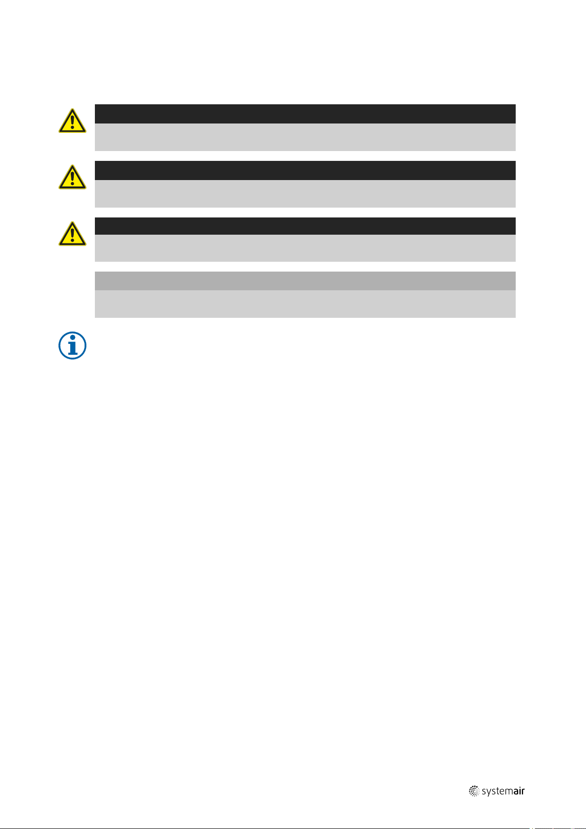
Danger
Direct hazard
Failure to comply with this warning will lead directly to death or to serious injury.
Warning
Potential hazard
Failure to comply with this warning may lead to death or serious injury.
Caution
Hazard with a low risk
Failure to comply with this warning may lead to moderate injuries.
Important
Hazard with risk of damage to objects
Failure to comply with this warning will lead to damage to objects.
General information |
5
Note:
Useful information and instructions
1.1.1 Instruction symbols
Instruction
♦ Carry out this action
♦ (if applicable, further actions)
Instruction with xed sequence
1. Carry out this action
2. Carry out this action
3. (if applicable, further actions)
2 Safety notes
Planners, plant builders and operators are responsible for the proper assembly and intended use.
♦ Read the operating instructions completely and carefully.
♦ Keep the operating instructions and other valid documents, such as the circuit diagram or motor instructions, with
the fan. They must always be available at the place of use.
♦ Observe and respect local conditions, regulations and laws.
♦ Only use the fan in a awless condition.
♦ Provide generally prescribed electrical and mechanical protective devices.
♦ During installation, electrical connection, commissioning, troubleshooting, and maintenance, secure the location and
premises against unauthorised access.
♦ Do not circumvent any safety components or put them out of action.
♦ Keep all the warning signs on the fan complete and in a legible condition.
♦ The device is not to be used by persons (including children) with reduced physical, sensory or mental capabilities, or
lack of experience and knowledge, unless they have been given supervision or instruction.
♦ Do not allow children to play with the device.
| 002
Page 6
Warranty GB
|
6
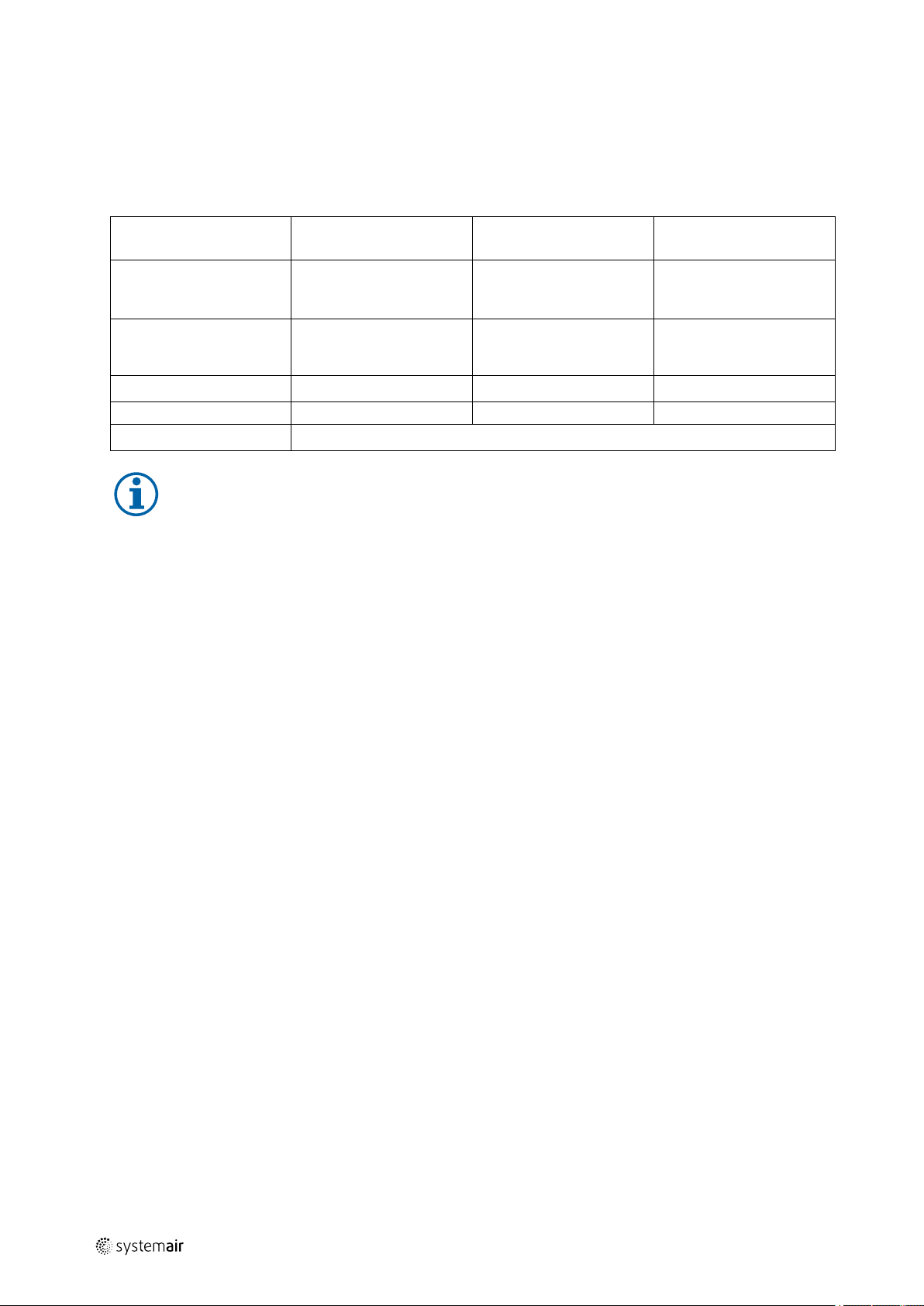
2.1 Personnel
The fan may only be used by qualified, instructed and trained personnel. The persons must know the relevant safety directives in order to recognise and to avoid risks. The individual activities and qualifications can be found in Table 1 Qual-
ifications, page 6.
Table 1 Qualifications
Activities
Storage, operation,
transport, cleaning,
disposal
Electrical connection,
commissioning, electrical
disconnection
Installation, disassembly
Maintenance
Repair
Electrical expert or
matching qualification
X
X X
Smoke extraction fans and EX fans only by agreement with Systemair.
Fitter or matching
qualification
Note:
The operator is responsible for ensuring that personnel are instructed and have understood the contents of
the operating instructions. If something is unclear, please contact Systemair or its representative.
2.2 Personal protective equipment
Wear protective equipment during all work in the vicinity of the fan.
• protective working clothes
• protective working shoes
• protective working gloves
• helmet
Trained personnel (see
following note)
X
X
• goggles
• hearing protection
2.3 5 rules of electrical safety
• Disconnect (disconnection of the electrical system from live components at all terminals)
• Prevent reactivation
• Test absence of voltage
• Ground and short-circuit
• Cover or restrict adjacent live parts
3 Warranty
The warranty for our products is determined by the contractual stipulations, our offers and our Terms and Conditions.
Warranty claims presuppose that the product is properly connected, operated according to data sheets and serviced as
needed. A correct commissioning report must also be presented upon request. Please find the commissioning report attached to this document.
4 Delivery, transport, storage
4.1 Safety information
Warning: Risk from rotating fan blades
♦ Prevent access by unauthorised persons by safety personnel or access protection.
Warning: Suspended loads
♦ Wear protective equipment during all work in the vicinity of the fan, details see 2.2 Personal protective equipment,
page 6.
♦ Do not walk under suspended loads.
| 002
Page 7

GB
♦ Make sure that there is nobody under a suspended load.
Delivery, transport, storage |
4.2 Delivery
Each fan leaves our plant in an electrically and mechanically proper condition. We recommend transporting the fan to
the installation site in the original packaging.
Checking delivery
♦ Check the packaging and the fan for transport damage. Any findings should be noted on the cargo manifest.
♦ Check completeness of the delivery.
Unpacking
Warning
When opening the transport packaging, there is a risk of damage from sharp edges, nails, staples,
splinters etc.
♦ Unpack the fan carefully.
♦ Check the fan for obvious transport damage.
♦ Only remove the packaging shortly before assembly.
♦ Wear protective equipment during all work in the vicinity of the fan, details see 2.2 Personal protective
equipment, page 6.
7
4.3 Transport
4.3.1 Safety information
Warning: Electrical or mechanical hazards due to fire, moisture, short circuit or malfunction.
♦ Never transport the fan by the connecting wire, terminal box, rotor, protection grille, inlet cone or silencer.
♦ In open transport, please make sure that no water can penetrate into the motor or other sensitive parts.
♦ We recommend transporting the fan to the installation site in the original packaging.
Caution: If transported without care during loading and unloading, the fan may be damaged.
♦ Load and unload the fan carefully.
♦ Use hoisting equipment that is suitable for the weight to be hoisted.
♦ Observe the transportation arrows on the packaging.
♦ Use the fan packaging exclusively as transport protection and not as a lifting aid.
4.4 Storage
♦ Store the fan in the original packaging in a dry, dust-free location protected against weather.
♦ Avoid the effects of extreme heat or cold.
Important
Hazard due to loss of function of the motor bearing
♦ Avoid storing for too long (recommendation: max. 1 year).
♦ Turn the rotor manually every three months, wear safety gloves when doing this.
♦ Check that the motor bearing functions properly before installation.
| 002
Page 8
Description IV Smart GB
|
8
5 Description IV Smart
5.1 IV Smart EC equipped with an EC motor
The fans are driven by two EC motors. These motors are delivered with a pre-wired potentiometer (0–10 V) that allows
you to easily find the required working point of the fan. All motors are suitable for 50/60 Hz. The input voltage for single-phase units can vary between 200 and 277 V.
5.2 IV Smart AC — equipped with an AC motor
The fans are driven by two AC motors. All motors are suitable for 50/60 Hz.
5.3 IV Smart EC—CO — equipped with a carbon monoxide control unit
The fans are driven by two EC motors (see 5.1 IV Smart EC equipped with an EC motor, page 8). The fan and the control
unit are pre—wired and ready for use.
5.3.1 Carbon monoxide control unit
The CO control unit controls two EC fans with a 0–10 V control signal originating from a CO sensor. Both fans are controlled with the same 0–10 V signal and monitored for fan failure. The CO alarm is triggered based on the threshold and
time specifications of DIN EN 50291-1.
5.3.2 Information on the effects of CO on humans
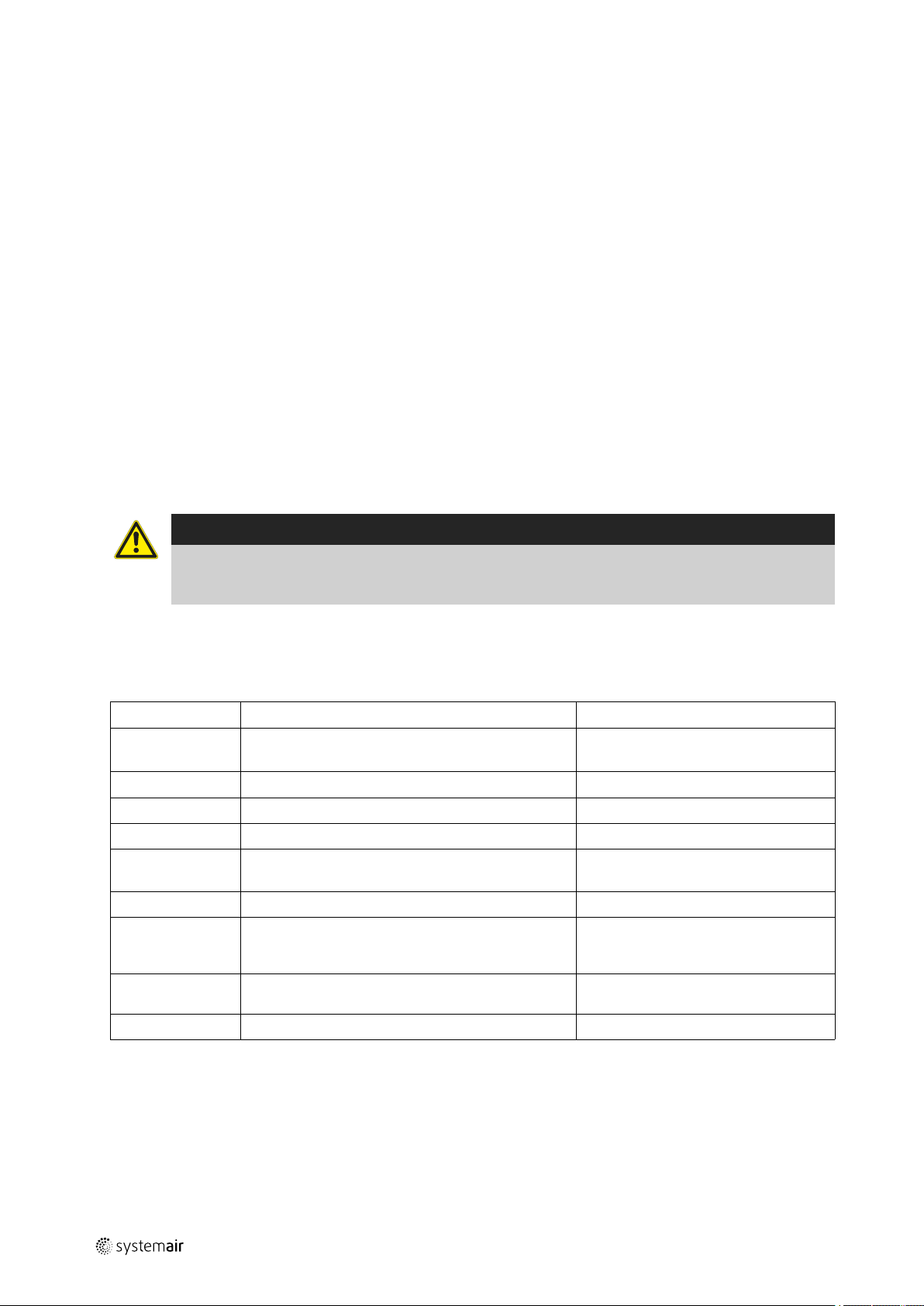
Warning
This CO control unit is designed to protect people from the acute effects of carbon monoxide. It cannot
prevent the chronic effects of carbon monoxide exposure. The CO control unit can not fully protect people at
special risk, such as those with particular medical conditions. In cases of doubt, consult a doctor.
The table below sets out the symptoms, the corresponding CO concentrations and lengths of time that a person needs
to be exposed to this concentration until symptoms occur.
Table 2 Influence of carbon monoxide on the human body
CO concentration
30 ppm
100 ppm
200 ppm
300 ppm
400 ppm
800 ppm
1600 ppm
3200 ppm
8000 ppm
Symptoms
Maximum workplace concentration for 8 hours of
work, no symptoms
Even after a prolonged period, no symptoms
Headache 2…3 h
Mild headache, dizziness, weakness, nausea 2…3 h
Frontal headache
Life-threatening
Headache, dizziness, nausea, convulsions Within 45 min
Headache, dizziness and nausea
Loss of consciousness
Possible death
Headache, dizziness and nausea
Death
Death A few minutes
Time until occurrence of symptoms
-
-
1…2 h
3 h
Within 20 min
Within 2 h
Within 1 h
Within 5…10 min
Within 25…30 min
| 002
Page 9
GB Description IV Smart
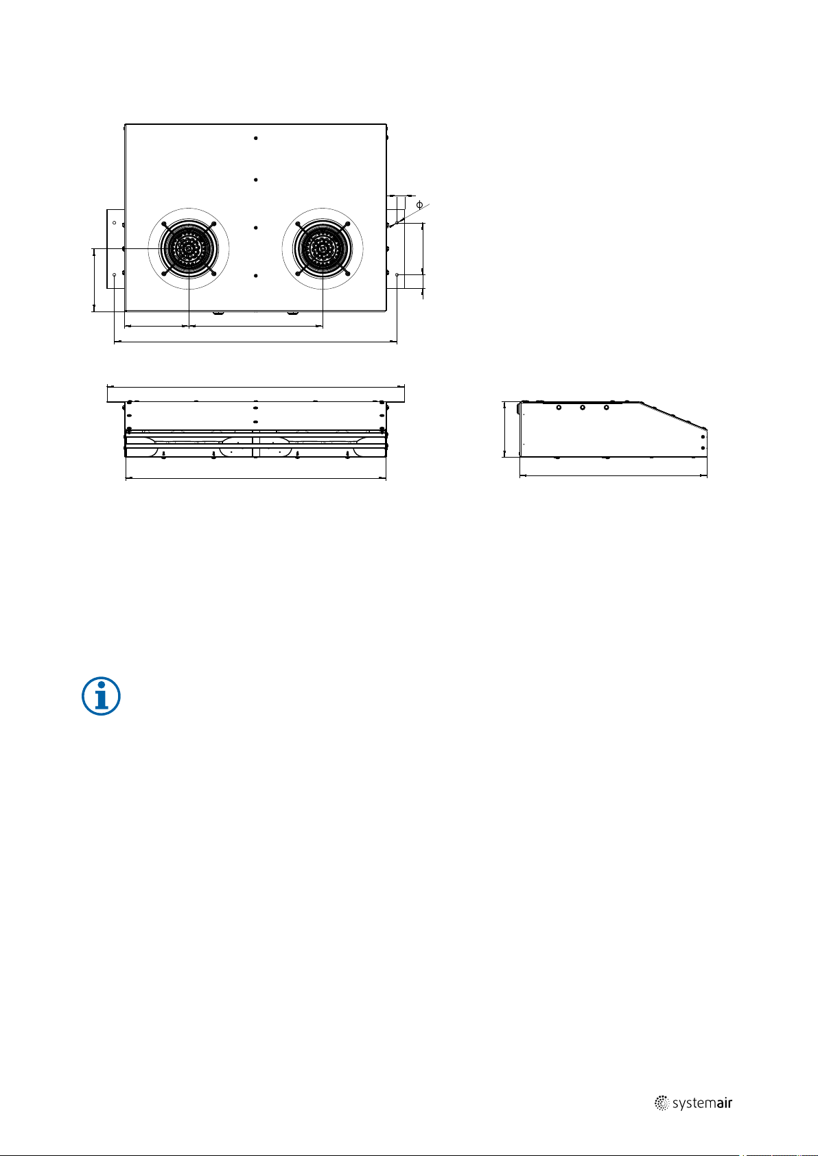
169
760
36 140
150
800
700
8
503
173 360
20
5.4 Dimensions
|
9
Fig. 1 Dimensions IV Smart
5.5 Technical data of the fan
• IV Smart AC: Temperature range [°C] of transported air = -25 to 55
• IV Smart EC: Temperature range [°C] of transported air = -25 to 55
• IV Smart EC CO: Temperature range [°C] of transported air = -20 to 40
• Voltage/current/enclosure class/weight/impeller diameter = see name plate
• Sound pressure [dB(A)] = see data sheet
Note:
Further technical data can be found on the data sheet of your fan.
| 002
Page 10
Description IV Smart GB
|
10
5.6 Technical data of the controller
Voltage = 100…240 VAC
Frequency = 50…60 Hz
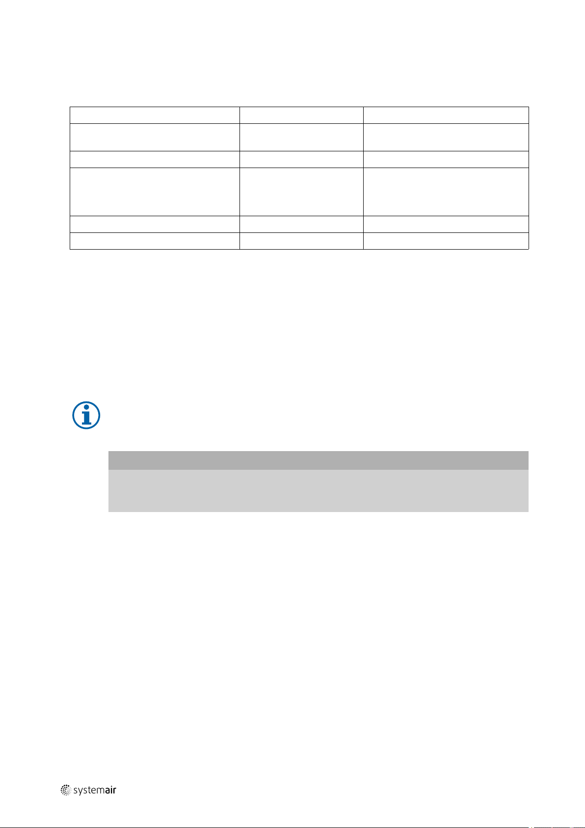
Table 3 CO control unit components
Component
Fan
CO sensor
External alarm device (optional)
Function
Two fans with a 0-10 V control input and hall output, for ventilation of the
room being monitored.
CO sensor with 4…20 mA measuring signal output that reflects a 0…300
ppm CO concentration.
Connection of an alarm siren or alarm light
5.7 Motor data
The motor data can be found on the name plate of the motor, or in the technical documents of the motor
manufacturer.
5.8 Intended use of all IV Smart versions
• The fans are intended for installation in underground and above-ground parking structures, to facilitate ventilation
and cold smoke extraction.
• For optimum operation, the jet fan must be suspended horizontally from the ceiling in such a position that intake and
outlet are unobstructed.
• The maximum admissible operating data on the name plate apply to an air density of 1.2 kg/3³ (sea level) and a
maximum air humidity of 80%.
• The fan is suitable for conveying clean air, with a density of 1.3 kg/m3 and a max. air humidity of 95%.
5.9 Incorrect use
Incorrect use refers mainly to using the fan in another way to that described. The following uses are incorrect and
hazardous:
• Conveying of explosive and combustible media
• Conveying of aggressive media
• Installation outside
• Operation in an explosive atmosphere
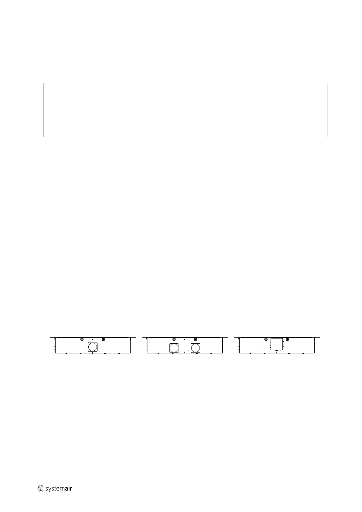
5.10 Terminal boxes
IV Smart AC IV Smart EC IV Smart CO
| 002
Page 11
GB
Serial.no: 84543/1002773290-001/20170131
IV Smart EC
230 V~
50 Hz
IP54
䰊
2510 min ¹
17kg
0,35 kW
Made in GER MANY
INS.CL.B
2,6 A
www.systemair.com
1
2
3
4
5
6
7
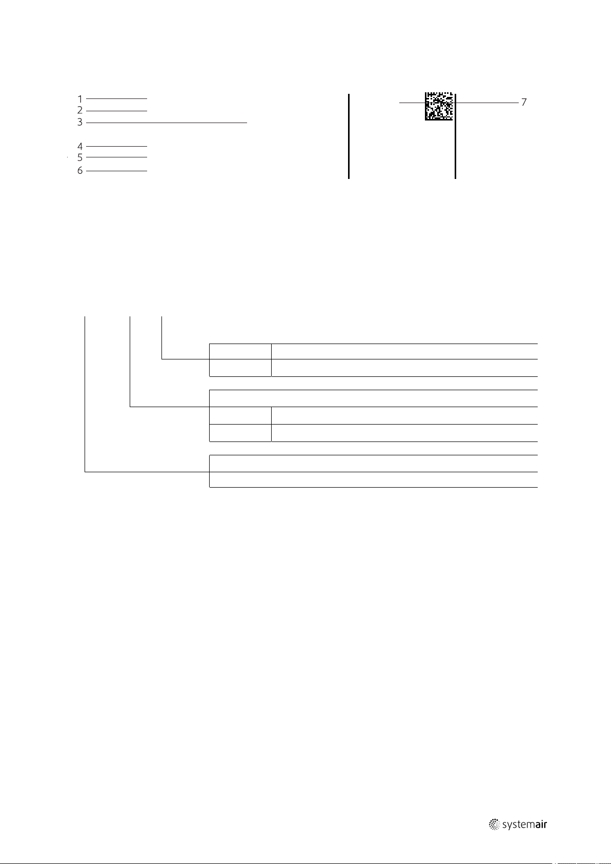
6 Name plate and type key
Name plate and type key |
11
1
Type designation
2
Voltage/current/frequency
3 Input power 7
4
Enclosure class/fan impeller speed/
weight
Table 4 Type key
IV Smart EC
-
-
CO
EC
AC
Induction fan Smart
5
Insulation class
6
Article number/production number/manufacturing date
Certifications
No controller
Equipped with a carbon monoxide control unit
Motor type
Electronically commutated/1 phased
2 poled/voltage controllable/1 phased
Fan type
| 002
Page 12
| Installation
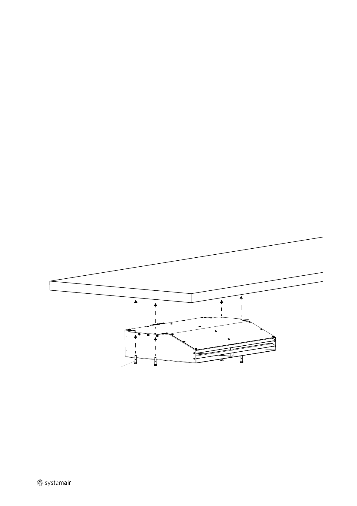
4x
12
7 Installation
Warning: Danger from falling fan or fan parts.
♦ Check the surface before installation for load bearing capacity.
♦ Consider all static and dynamic loads when selecting hoisting equipment and fastening components.
General safety information
♦ Installation may only be carried out by adequately qualified persons, details see Table 1 Qualifications, page 6.
♦ Wear protective equipment during all work in the vicinity of the fan, details see 2.2 Personal protective equipment,
page 6.
♦ Abide by the system-related conditions and requirements of the system manufacturer or plant constructor.
♦ Do not dismantle or circumvent safety elements, or put them out of function.
♦ Provide contact and intake protection and ensure safety distances according to DIN EN ISO13857 and DIN 24167-1.
♦ Prevent the possibility of foreign bodies being drawn in.
7.1 Preconditions
♦ Ensure that the fan and all its components are undamaged.
♦ Ensure that the information on the name plates (fan and motor) matches up with the operating conditions.
♦ Ensure that there is enough space to install the fan.
♦ Protect against dust and moisture when installing.
♦ Fit the fans in such a way that there is sufficient access for troubleshooting, maintenance and repair.
GB
7.2 Installation on the ceiling
Installation IV Smart
| 002
Page 13
GB
Electrical connection |
8 Electrical connection
8.1 Safety information / Preconditions
Warning: Danger from electrical voltage!
♦ Observe the 5 rules of electrical safety, see 2.3 5 rules of electrical safety, page 6.
♦ Prevent the ingress of water into the connection box.
♦ Electrical connection may only be carried out by adequately qualified persons, details see Table 1 Qualifications, page
6.
♦ Observe and respect local conditions, regulations and laws.
♦ Wear protective equipment during all work in the vicinity of the fan, details see 2.2 Personal protective equipment,
page 6.
8.2 Preconditions
♦ Abide by the system-related conditions and requirements of the system manufacturer or plant constructor.
♦ Safety elements may not be dismantled, circumvented or deactivated.
♦ Install a circuit breaker in the permanent electrical installation, with a contact opening of at least 3 mm at each pole.
8.3 Connection
13
♦ Check if the data on the nameplate matches the connection data.
♦ Complete the electrical connection according to the circuit diagram.
♦ Lay the connection cables in the terminal box in such a way that allows the cover of the terminal box to be closed
without resistance.
♦ Use all of the locking screws.
♦ Insert the screws by hand to avoid damaging the thread.
♦ Tighten all glands well in order to guarantee protection class IP.
♦ Screw the lid of the terminal box/inspection switch evenly tight.
♦ Connect the cable end in a dry environment.
8.3.1 Wiring diagram IV Smart AC
Color
Black
Blue
Green/Yellow
L
N
PE
Function/pin assignment
Power supply 230 V AC, 50...60 Hz
Neutral conductor
Protective conductor
| 002
Page 14
| Electrical connection
14
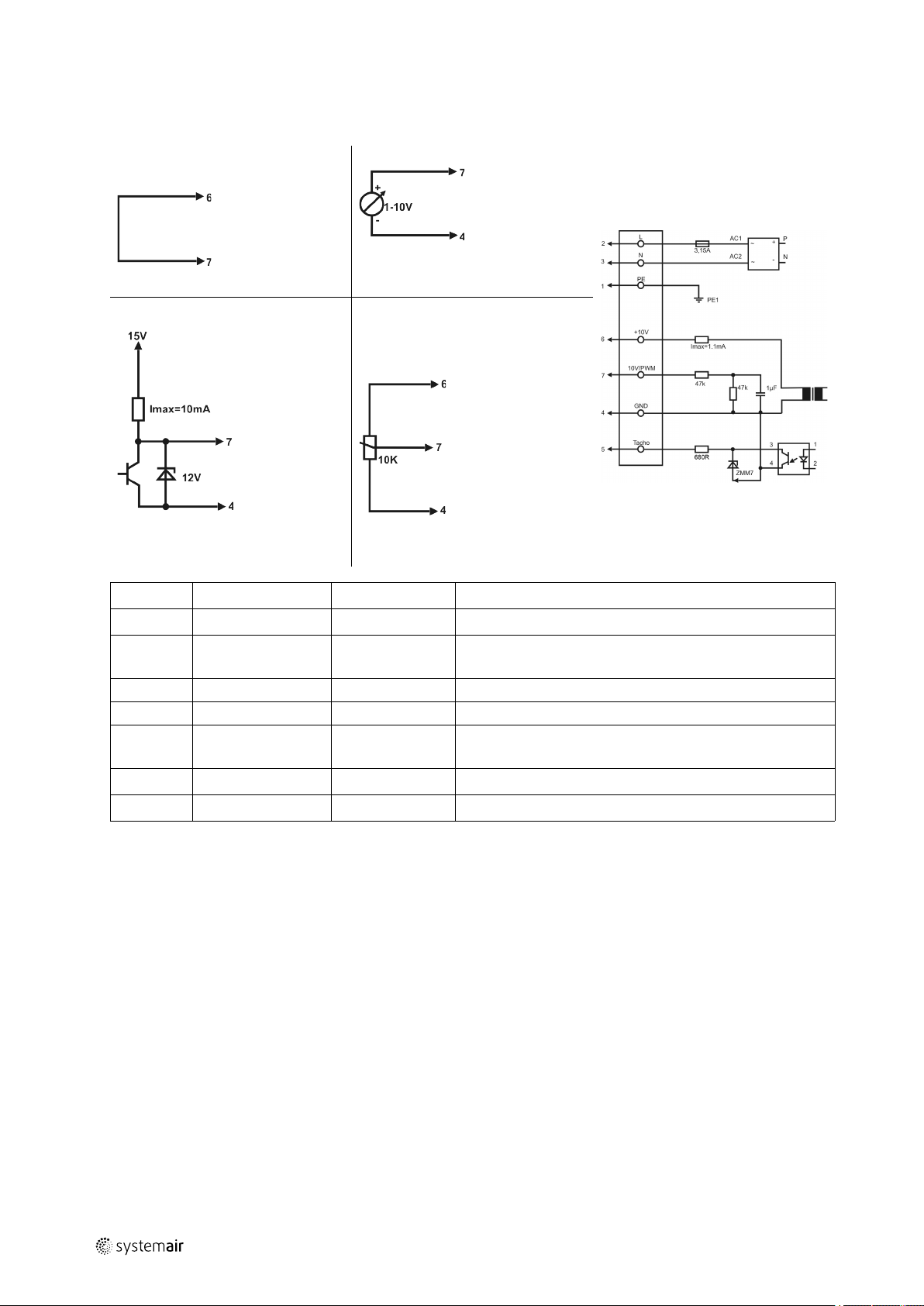
8.3.2 Wiring diagram IV Smart EC
Client side
Max. speed
Adjustable speed through PWM
1...10 KHz
GB
Adjustable speed
10V –> n = max
1V –> n = min
<1V –> 0
Adjustable speed through
potentiometer
100 % PWM –> n = max
10 % PWM –> n = min
< 10 % –> 0
Wire no. Connection
1 PE
2 L
3 N
4 GND
5
6
7 0...10 V PWM
speedometer white Speed output: Open Collector, 1 impulse per revolution,
10 V/max. 1,1 mA red Voltage output 10 V/1.1 mA
Color
green/yellow Protective conductor
brown Power supply 230 V AC, 50...60 Hz, see name plate for
blue Neutral conductor
blue GND-connection of the controller interface
yellow Controller input 0...10 V or PWM
Function/assignment
voltage range
electrically isolated, Isink_max = 10 mA
| 002
Page 15
GB
Electrical connection |
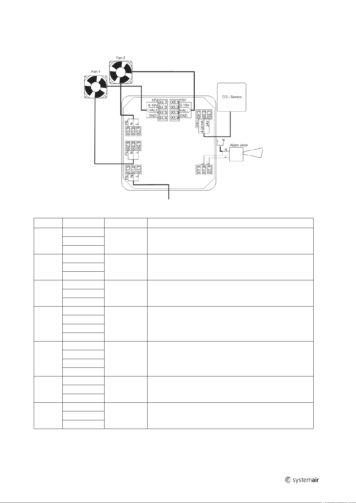
8.3.3 Wiring IV Smart EC-CO
The wiring diagram of the IV Smart EC-CO fan is not included in this document, but within this delivery.
15
Table 5 Electrical connections
Name Occupancy
1. L
X1
X2
X3
X4
X5
X6
X7
2. N
3. PE
1. L
2. N
3. PE
1. L
2. N
3. PE
1. 10 V
2. 0-10 V
3. HALL
4. GND
1. 10 V
2. 0-10 V
3. HALL
4. GND
1. 24 V
2. 4-20 mA
3. EARTH
1. NC
2. COM
3. NO
Designation Description
X1 SUPPLY
X2 FAN1
X3 FAN2
X4 FAN1
X5 FAN2
X6 SENSOR
X7 ALARM
Supply connection to the control unit
Supply connection to fan 1. Voltage corresponds to the control unit's
supply voltage
Supply connection to fan 2. Voltage corresponds to the control unit's
supply voltage
Control connection to fan 1. Speed specification and speed
feedback. If the fan has a 10 V output, it can be connected to
terminal X4.1.
Control connection to fan 2. Speed specification and speed
feedback. If the fan has a 10 V output, it can be connected to
terminal X5.1.
Connection for CO sensor supply connection and measuring signal
connection
Potential-free alarm contact connection option for controlling an
alarm siren or other auxiliary device.
8.3.3.1 Fan speed specification
The minimum fan speed can be set via a potentiometer in the range from 20 % to 40 %. The potentiometer is only accessible once the housing cover has been removed. The fan speed increases proportionately to the CO concentration
until the maximum speed at 50 ppm. If a fault is detected, the fans operate at maximum speed in order to remove any
| 002
Page 16
Commissioning GB
|
16
raised CO concentrations in the air. The following table provides information about the control unit's speed specifications to the fans.
Table 6 Fan speed specification
CO concentration
CO < 15 ppm Switch-off hysteresis 10
ppm
CO = 15 ppm
15 ppm < CO ≤ 50 ppm Min.…10 V
50 ppm < CO 10 V
Fault
Speed specification values
0 V
2 V…4 V (min.)
10 V
Comment
Fan standstill
Speed depending on set value
Linear rise in the characteristic curve
analogue to the CO concentration
starting with the minimum through to
the maximum fan speed
Maximum fan speed
Maximum fan speed
8.4 Protective grounding wire
The protective grounding must have a cross-section equal to or greater than that of the phase conductor.
8.5 Residual current circuit breaker
All-current-sensitive residual current circuit breakers are required for use in alternating-current systems with 50/60 Hz,
in combination with electronic devices such as EC motors, frequency converters or uninterruptible power supplies
(UPS).
8.6 Protecting the motor
Note:
In fans equipped with an EC motor, there is no additional motor protection needed. The motor protection is
integrated in the electronics of the motor.
Important
Damage to motor due to overcurrent, overload or short circiut.
♦ Use (all-pole) circuit breaker (characteristic C or K) or motor protection switches.
♦ Always connect thermo-contacts or cold conductors to a motor protection switch.
9 Commissioning
9.1 Safety information
♦ Commissioning may only be carried out by adequately qualified persons, details see Table 1 Qualifications, page 6.
♦ Wear protective equipment during all work in the vicinity of the fan, details see 2.2 Personal protective equipment,
page 6.
9.2 Preconditions
♦ Installation and electrical connection have been correctly performed.
♦ Residual material from installation and foreign objects have been removed from the fan and ducts.
♦ Inlet and outlet are free.
♦ Safety devices have been fitted.
♦ Ground cable is connected.
♦ Cable glands are tight.
♦ Nominal current (from the name plate) is not exceeded.
♦ Data on the name plate corresponds with the connection data.
| 002
Page 17

GB Commissioning
|
9.3 Commissioning Report
Important
• It is recommended to fill out the commissioning report 16 Commissioning Report, page 24.
• Please keep the completed commissioning report in a safe place. In the case of a warranty claim, this
report can be requested by Systemair GmbH. This document can also be downloaded from our online
catalogue.
9.4 Tests before activation
♦ Check that safety elements and protection grilles are securely fastened.
9.5 Tests (AC motor)
1. Before switching the fan on, check for externally visible damage and ensure that the protective equipment functions
properly.
2. Switch the fan on.
3. Checks:
♦ Direction of rotation/conveyance. The direction of rotation always applies looking at the rotor
• The direction of rotation is best observed just before the fan stops.
♦ Smooth running (any vibrations and noise)
♦ Current consumption
♦ Compare the current consumption with the nominal consumption on the name plate.
♦ Tightness of all connections
4. Switch the fan off.
17
9.6 Tests (EC motor)
1. Before switching the fan on, check for externally visible damage and ensure that the protective equipment functions
properly.
When the mains are switched on, the motor starts an initialization (a few seconds). After the initialization the control
input is active.
2. Switch the fan on via the control input.
3. Checks:
♦ Direction of rotation/conveyance. The direction of rotation always applies looking at the rotor
• The direction of rotation is best observed just before the fan stops.
♦ Smooth running (any vibrations and noise)
♦ Current consumption
♦ Compare the current consumption with the nominal consumption on the name plate.
♦ Tightness of all connections
4. Switch the fan off via the control input.
9.7 Tests when activated EC CO version
9.7.1 Function test
A function test is carried out once the voltage supply is connected, with the displays, the potential-free contact and the
fans being switched on briefly. The control unit has been installed correctly if the power display lights up permanently,
the CO alarm and fault display goes out after 2 seconds and the audible display does the same after 1 second. The potential-free contact must tighten after 1 second and therefore establish a connection between X7.2 and X7.3. In addition, no faults must be displayed after around 15 seconds. In the Chapter 9.7.3 Visual and audible display, page 18 the
meaning of the different signal types are explained.
| 002
Page 18

Operation GB
|
18
9.7.2 Warm-up time
Once the operating voltage has been connected, the control unit is in a warm-up state for around 6.5 minutes. During
this time, no CO measurements are carried out and no CO alarms are triggered. To ensure basic ventilation and to remove any raised CO concentrations in the air, the fans are controlled at a minimum speed. The warm-up time is needed
to give the CO sensor enough time for the CO measuring transducer's warm-up phase. Once the warm-up time has
elapsed, the control unit switches to its normal operating state (ready) and CO analysis takes place.
9.7.3 Visual and audible display
The table below distinguishes between the displays based on the control unit's four operating modes.
Table 7 Visible and audible display
Operating mode Audible signal
generator
Warm-up time No No On No
Ready
CO alarm
Fault 2 fast sounds / min
No No On No
On
CO alarm
Red LED
Rapid flashing 2 Hz
No On
Operation
Green LED
On No
Fault
Yellow LED
Rapid flashing 2 Hz
Table 8 Carbon monoxide alarm thresholds
CO concentration for activation of
the CO alarm
30 ppm
50 ppm
100 ppm
300 ppm
Control unit trigger times CO concentration for resetting of the
active CO alarm
No alarm No alarm
After around 75 min
After around 25 min
After around 1 min
< 40 ppm
< 40 ppm
< 40 ppm
10 Operation
10.1 Safety information
Warning: Hazard from electrical voltage or moving components.
♦ The device may only be operated by adequately qualified persons, details see Table 1 Qualifications, page 6.
♦ The device may only be operated by people who are instructed in and have understood the function and risks, and
can act accordingly.
♦ Abide by the system-related conditions and requirements of the system manufacturer or plant constructor.
10.2 Preconditions
♦ Ensure access only to persons who can safely handle the device.
♦ Only use the fan in accordance with the operating instructions and the operating instructions for the motor.
♦ Do not dismantle or circumvent safety elements, or put them out of function.
| 002
Page 19

GB
Troubleshooting/maintenance/repair/CO alarm |
11 Troubleshooting/maintenance/repair/CO alarm
11.1 Safety information
♦ Troubleshooting/maintenance/repair may only be carried out by adequately qualified persons, details see Table 1
Qualifications, page 6.
♦ Wear protective equipment during all work in the vicinity of the fan, details see 2.2 Personal protective equipment,
page 6.
♦ Observe the 5 rules of electrical safety, see 2.3 5 rules of electrical safety, page 6.
♦ Abide by the system-related conditions and requirements of the system manufacturer or plant constructor.
♦ The rotor must be at a standstill.
11.2 Troubleshooting Fan
Table 9 Troubleshooting
Problem Possible causes Remedy
Fan does not run
smoothly
Rotor imbalance Rebalancing by a specialist company
Soiling on the rotor Clean carefully, rebalance
Material decomposition on the
rotor due to aggressive material
conveyed
Rotor rotates in wrong direction
Contact Systemair
Contact Systemair
19
Air output of fan too
low
Fan does not reach
nominal speed
Motor does not
rotate
Electronics/motor
overheated
Deformation of rotor due to
excessive temperature
Vibrations, oscillations Check the installation of the fan
Rotor rotates in wrong direction
Flow regulators not or only
partly open
Improperly aligned drive motor
Control units (if used) such as
frequency converter or
transformer are set incorrectly.
Mechanical blockage Remove the blockage
Faulty supply voltage Check the supply voltage, re-establish the voltage supply
Faulty connection Disconnect from the power supply, correct the
Temperature monitor has
responded
Insufficient cooling Improve cooling.
Overloaded motor Check if the correct fan is used for your application.
Ambient temperature too high Check if the correct fan is used for your application.
Ensure that the temperature does not exceed the certified
value/Install new rotor
Contact Systemair
Check opening position on site
Contact Systemair
Correct the settings of the control units.
connection, see circuit diagram.
Allow the motor to cool down, find and resolve the cause
of the fault.
Note:
For all other damage/defects, please contact Systemair. Defective fans must be completely replaced.
11.3 Alarm and fault handling Carbon monoxide control unit
The control unit continuously monitors the sensor's function, as well as the function of the fans. The following subpoints describe the the meaning of the fault and CO-Alarm display and the way in which they should be responded to.
| 002
Page 20

| Troubleshooting/maintenance/repair/CO alarm
20
11.3.1 Thresholds for fault displays
The control unit distinguishes between two fault types, which are specified in more detail in the table below.
Table 10 Fault display thresholds
GB
Fault type Setting threshold Reset threshold
Fan failure RPM < 130 rpm /
min
I
Sensor fault
< 3.0 mA I
4-20mA
RPM ≥ 180 rpm / min Fan fault or fault with the fan supply cables
≥ 3.5 mA
4-20mA
Comment
–> Signalled after 10 seconds
Short circuit or break in the sensor cable
–> Signalled after 3 seconds
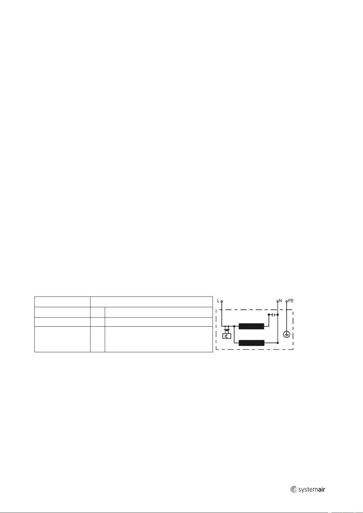
11.3.2 Potential-free alarm contact
The illustration below explains the alarm contact's switching states.
Control terminals e.g. to connect an alarm signal
CO alarm — fault or voltage free Operating ok
11.3.3 Behaviour in the event of a CO alarm and fault handling
The control unit distinguishes between two fault types, which are specified in more detail in the table below.
Table 11 Behaviour in the event of a CO alarm and faults
No.
1
2
Problem Possible cause
CO alarm
Fault
Critical CO concentration
reached
- Fan failure
- Sensor fault
Remedy / suggested solution
1. If the fan and control unit is installed in a garage
and your vehicle engine is idling, switch the engine
off.
2. Leave the room immediately and seek fresh air.
Check that everyone is present. Do not go back
into the room before it has been ventilated and the
CO alarm has stopped.
3. If the alarm triggers again after 24 hours, repeat
steps 1-2 and call the emergency gas services
(please check you have their number now) and if
necessary notify the relevant gas fitter.
Contact Systemair
11.4 Maintenance
To ensure a reliable operation of the fan, we recommend periodic maintenance intervals. These maintenance intervals
must be specified by the operator. The frequency of maintenance activities or additional activities must be decided according to the use of the fans. It is important for traceability to create a maintenance plan, in which the work performed
is written down.
The maintenance intervals should be shorter if the following conditions (among others) apply:
• Fan used as kitchen exhaust application
• Ambient temperature > 40°C or < -10°C, or temperature variations > 20k
| 002
Page 21

GB
The following check list provides points of reference for the tasks to be carried out.
Table 12 Activities
Cleaning |
21
Activity
Check the fan and components for visible damage, corrosion and
contamination
Inspect the the rotor for damage and imbalance
Check that the condensate drain functions correctly
Clean the fan/ventilation system (see Chapter Cleaning)
Inspect screwed connections and tighten them if necessary
Ensure that the intake of the fan is free from dirt
Check that fan and components are being used as intended
Check the current consumption
Check that the vibration dampers function correclty (if used)
Check that the electrical and mechanical protective devices function
correctly
Check if the name plate of the fan is legible
Check that connection terminals and cables glands are tightly screwed and
have no visible damage/defects
Check flexible connections for leaks
Note:
If you have questions, please contact Systemair. Defective fans must be completely replaced.
As required Periodic intervals
X
X
X
X
X
X
X
X
X
X
X
X
X
11.5 Spare parts
♦ Use original spare parts from Systemair only.
♦ When ordering spare parts, please specify the serial number of the fan. This can be found on the name plate.
12 Cleaning
12.1 Safety information
♦ Cleaning may only be carried out by adequately qualified persons, details see Table 1 Qualifications, page 6.
♦ Wear protective equipment during all work in the vicinity of the fan, details see 2.2 Personal protective equipment,
page 6.
♦ Observe the 5 rules of electrical safety, see 2.3 5 rules of electrical safety, page 6.
♦ Ensure that the power supply has been switched off (all-pole circuit breaker).
♦ Ensure that the rotor is at a standstill.
12.2 Procedure
Important
Keeping the fan clean extends its service life.
♦ Install a filter monitor.
♦ Do not use steel brushes or sharp-edged objects.
♦ Do not use a high-pressure cleaner (steam jet cleaner) under any circumstances.
♦ Do not bend the fan blades when cleaning.
♦ When cleaning the rotor, pay attention to balance weights that have been positioned
♦ Keep the airways of the fan clear and clean them if necessary with a brush.
| 002
Page 22

| Deinstallation/dismantling
22
13 Deinstallation/dismantling
Deinstall and dismantle the fan in reverse order of installation and electrical connection.
14 Disposal
♦ Ensure material is recycled. Observe national regulations.
♦ The device and the transport packaging are predominantly made from recyclable raw materials.
♦ Disassemble the fan into its components.
♦ Separate the parts according to:
• reusable material
• material groups to be disposed of (metal, plastics, electrical parts, etc.)
GB
| 002
Page 23

GB
15 EU Declaration of conformity
The manufacturer: Systemair GmbH
Seehöfer Straße 45
DE-97944 Boxberg
Germany
+49 (7930) 9272 - 553
Product designation: Jet fans
EU Declaration of conformity |
23
Type designation:
Since of manufacture:
The manufacturer declares that the above mentioned products in their design and construction and the version
marketed by us complies with the Harmonization legislation listed below:
EU directives: 2006/42/EC Machinery directive
Regulations: 327/2011 Only for fans above 125W, CE marked fans
The following standards have been considered:
Harmonized standards:
AJR; AJ8; AJR (B); AJ8 (B); AJ (F); AJR-TR; IV; IV smart; prioJet
2016
2014/30/EU Directive electromagnetic compatibility
(EMC)
2011/65/EU RoHS directive
2009/125/EC ErP guidelines
used as components are CE marked by other
manufacturer.
DIN EN ISO 12100:2013
DIN EN 60204-1:2010
DIN EN 61000-6-1:2007
DIN EN 61000-6-2:2011
DIN EN 12101-3:2015*
Safety of machinery - General principles for
design Riskassessment and risk reduction
Safety of machinery - Electrical equipment of
machines - Part1: General requirements
Electromagnetic compatibility (EMC) - Part 61: Generic standards - Immunity for
residential, commercial and light-industrial
environments
Electromagnetic compatibility (EMC) - Part 62: Generic standards - Immunity for industrial
environments
Smoke an heat control systems, Part 3:
Specification for powered smoke and heat
exhaust ventilators
Boxberg, 20.04.2016
| 002
ppa. Harald Rudelgass, technical director
Page 24

Commissioning Report GB
|
24
16 Commissioning Report
Fan
Description:
Article no.: Manufacturing order no.:
Installer
Company: Contact person:
Company address:
Tel. no.: Email:
Operator (Place of installation)
Company: Contact person:
Company address:
Tel. no.: Email:
Type of connection
Directly to mains
0-10 V signal (EC motor)
via contactor control
Transformer
Frequency converter
Sinus filter
Shielded cables
Motor protection
Motor protection switch or motor protection relay
PTC resistor
Resistance value [Ω]:
Thermal contact
Electrical motor protection
Others:
Functional check
Impeller easily rotatable (by hand)
Rotation direction acc. to directional arrow
Yes No
□ □
□ □
□ □
□ □
□ □
□ □
□ □
Yes No
□ □
□ □
□ □
□ □
Yes No
□ □
□ □
Nominal data - Fan (name plate on fan housing)
Voltage [V]: Current [A]:
Frequency [Hz]: Power [kW]:
Fan impeller speed [rpm]:
| 002
Page 25

GB Commissioning Report
Measured data at commissioning
Voltage [V]: Temp. of transported air [°C]:
|
25
Current L1 [A]*:
Fan impeller speed [rpm]:
Current L2 [A]: Air volume [m3/s]:
Current L3 [A]:
*For single-phase fans, fill in line “Current L1 [A]” *Δ- Pressure between suction-side and discharge of the fan
Differential pressure [Pa]*:
If an air flow measurement is not possible, this value can be calculated using the following formula:
=
Air volume [m³/s]:
Duct cross-section [m²]
X
Flow speed [m/s]
Grille measurement acc. to VDI 2044
Yes No
Commissioning of the fan successful?
□ □
Date, installer's signature
Date, operator's signature
Please keep the completed commissioning report in a safe place. In the case of a warranty claim, this report can
be requested by Systemair GmbH. This document can also be downloaded from our online catalogue.
For technical questions, please contact the technical support division of Systemair GmbH (tel. +49 7930/9272 730).
| 002
Page 26

DE
Montage- und Betriebsanleitung
© Copyright Systemair AB
Alle Rechte vorbehalten
E&OE
Systemair AB behält sich das Recht vor, seine Produkte ohne Vorankündigung zu ändern.
Dies gilt auch für bereits bestellte Produkte, sofern die vorher vereinbarten Spezifikationen nicht beeinflusst werden.
DE
| 002
Page 27

Inhaltsverzeichnis
1 Allgemeine Hinweise ...... ..... ..... ........... ..... ..... 29
1.1 Hinweissymbole .... ..... ..... ...... ..... ..... .... 29
1.1.1 Anleitungssymbole... ..... ........... 29
2 Sicherheitshinweise.... ..... ..... ...... ..... ..... ..... .... 29
2.1 Personal. ..... ...... ..... ..... ..... ........... ..... .. 30
2.2 Persönliche Schutzausrüstung .......... ..... .. 30
2.3 Die 5 Sicherheitsregeln bei Arbeiten in
und an elektrischen Anlagen.. ..... ..... ....... 30
3 Gewährleistung ... ...... ..... ..... ..... ...... ..... ..... .... 30
4 Lieferung, Transport, Lagerung......... ..... ..... ...... 30
4.1 Sicherheitshinweise.... ..... ..... ..... . ..... ..... 30
4.2 Lieferung.......... ..... ..... ........... ..... ..... ... 31
4.3 Transport... ..... ........... ..... ..... ...... ..... ....31
4.3.1 Sicherheitshinweise... ..... . ..... ....31
4.4 Lagerung. . ..... ..... ..... ........... ..... ..... ...... 31
5 Beschreibung IV Smart ..... ..... ..... ........... ..... .... 32
5.1 IV Smart EC ausgestattet mit EC-
Motor ...... ..... ..... ........... ..... ..... ........... 32
5.2 IV Smart AC ausgestattet mit AC-
Motor ...... ..... ..... ........... ..... ..... ........... 32
5.3 IV Smart EC—CO — ausgestattet mit
Kohlenmonoxid-Steuerung... ..... ..... ..... ... 32
5.3.1 Kohlenmonoxid-
Steuerung... ...... ..... ..... ..... ...... . 32
5.3.2 Hinweise zu CO-
Auswirkungen auf
Menschen ......... ..... ..... ........... 32
5.4 Abmessungen ..... ........... ..... ..... ........... 33
5.5 Technische Daten der
Ventilatoren.... ..... ..... ...... ..... ..... ..... ..... 33
5.6 Technische Ventilatordaten .... ...... ..... ..... 34
5.7 Daten des Motors.. ..... ..... ...... ..... ..... ..... 34
5.8 Bestimmungsgemäße Verwendung
aller IV Smart-Versionen ..... ..... ........... ... 34
5.9 Bestimmungswidrige
Verwendung .... ..... ..... ........... ..... ..... .... 34
5.10 Klemmkästen ... ..... ..... . ..... ..... ..... ..... .... 34
6 Typenschild und Typenschlüssel . ..... ...... ..... ..... . 35
7 Installation.. ..... ..... . ..... ..... ..... ..... ...... ..... ..... .. 36
7.1 Voraussetzungen . ..... ........... ..... ..... ...... 36
7.2 Montage an der Decke ..... ..... ........... ..... 36
8 Elektrischer Anschluss . ..... ..... ..... . ..... ..... ..... .... 37
8.1 Sicherheitshinweise/
Voraussetzungen . ..... ........... ..... ..... ...... 37
8.2 Voraussetzungen . ..... ........... ..... ..... ...... 37
8.3 Anschluss . ..... ..... ..... ........... ..... ..... ...... 37
8.3.1 Anschlussplan IV Smart
AC .... ..... ........... ..... ..... ..........37
8.3.2 Anschlussplan IV Smart
EC.... ..... ..... ..... ...... ..... ..... ..... . 38
8.3.3 Anschlussplan IV Smart EC-
CO ... ..... ..... . ..... ..... ..... ..... . ..... 39
8.4 Schutzerdungsleiter . ..... ...... ..... ..... ..... ... 40
8.5 FI-Schutzschalter..... ..... ..... ...... ..... ..... ... 40
8.6 Motorschutz..... ..... ..... ..... ...... ..... ..... .... 40
9 Inbetriebnahme ..... ..... ........... ..... ..... ........... .. 40
9.1 Sicherheitshinweise.... ..... ..... ...... ..... ..... 40
9.2 Voraussetzungen . ..... ........... ..... ..... ...... 40
9.3 Inbetriebnahmeprotokoll.... ........... ..... .... 41
9.4 Tests vor der Aktivierung ... ..... ..... ..........41
9.5 Tests (AC-Motor) ...... ..... ..... ..... ...... ..... . 41
9.6 Testen Sie den Motor (EC-Motor)... ..... ..... 41
9.7 Tests bei Aktivierung EC-CO-
Version .... ..... ..... ...... ..... ..... ........... ..... 41
9.7.1 Funktionsprüfung . ..... ..... . ..... ....41
9.7.2 Aufwärmzeit . ..... ..... ..... ..... . ..... 42
9.7.3 Optische und akustische
Anzeige ......... ..... ..... ........... ... 42
10 Betrieb.... ..... ..... ..... ..... . ..... ..... ..... ...... ..... ..... 42
10.1 Sicherheitshinweise.... ..... ..... ...... ..... ..... 42
10.2 Voraussetzungen . ..... ........... ..... ..... ...... 42
11 Fehlersuche/Wartung/Reparatur/CO-
Alarm ..... ..... ...... ..... ..... ..... ...... ..... ..... ..... .....43
11.1 Sicherheitshinweise.... ..... ..... ...... ..... ..... 43
11.2 Fehlersuche Ventilator.. ..... . ..... ..... ..... .... 43
11.3 Alarm- und Fehlerbehandlung
Kohlenmonoxid-Steuerung... ..... ..... ..... ... 44
11.3.1 Schwellenwerte der
Fehleranzeigen ..... ..... ........... ... 44
11.3.2 Potentialfreier
Alarmkontakt ...... ..... ..... ..... .....44
| 002
Page 28

Inhaltsverzeichnis
12 Reinigung ..... ...... ..... ..... ..... ..... . ..... ..... ..... ..... 45
13 Demontage/Ausbau ........... ..... ..... ........... ..... . 46
14 Entsorgung ..... ..... ..... ........... ..... ..... ........... ... 46
15 EG-Konformitätserklärung.......... ..... ..... ........... 47
16 Inbetriebnahmeprotokoll.... ...... ..... ..... ........... .. 48
11.3.3 Verhalten bei CO-Alarm und
Fehlerbehandlung .... ..... ..... ..... . 44
11.4 Wartung....... ..... ..... ........... ..... ..... ....... 45
11.5 Ersatzteile ..... ..... ..... ........... ..... ..... ...... 45
12.1 Sicherheitshinweise.... ..... ..... ..... . ..... ..... 45
12.2 Vorgehensweise . ..... . ..... ..... ..... ..... . ..... . 46
DE
| 002
Page 29

DE
1 Allgemeine Hinweise
1.1 Hinweissymbole
Gefahr
Unmittelbare Gefährdung
Die Nichtbeachtung des Warnhinweises führt unmittelbar zum Tod oder zu schweren Verletzungen.
Warnung
Potenzielle Gefahr
Die Nichtbeachtung des Warnhinweises kann zum Tod oder zu schweren Verletzungen führen.
Vorsicht
Gefährdung mit geringem Risiko
Die Nichtbeachtung des Warnhinweises kann zu mittelschweren Verletzungen führen.
Wichtig
Gefahr mit Risiko für Sachbeschädigungen
Die Nichtbeachtung des Warnhinweises kann zu Sachbeschädigungen führen.
Allgemeine Hinweise |
29
Hinweis!
Nützliche Informationen und Anleitungen
1.1.1 Anleitungssymbole
Anleitung Anleitung mit fester Schrittfolge
♦ Führen Sie diese Handlung aus
♦ (ggf. weitere Handlungen)
1. Führen Sie diese Handlung aus
2. Führen Sie diese Handlung aus
3. (ggf. weitere Handlungen)
2 Sicherheitshinweise
Planer, Anlagenbauer und Betreiber sind für die ordnungsgemäße Montage und den bestimmungsgemäßen Betrieb
verantwortlich.
♦ Lesen Sie die Betriebsanleitungen vollständig und sorgfältig.
♦ Betriebsanleitungen und mitgeltende Unterlagen, wie elektrische Anschlussbilder oder Betriebsanleitungen des Mo-
tors, sind bei dem Ventilator aufbewahren. Sie müssen ständig am Einsatzort zur Verfügung stehen.
♦ Örtliche und nationale Gesetze und Regelungen sind zu beachten und einzuhalten.
♦ Der Ventilator darf nur in einwandfreiem Zustand verwendet werden.
♦ Es müssen die allgemein vorgeschriebenen elektrischen und mechanischen Schutzvorrichtungen bereitgestellt
werden.
♦ Sichern Sie während der Montage, elektrischem Anschluss, Inbetriebnahme, Fehlersuche, Fehlerbehebung und War-
tung die Montagestelle und die Räumlichkeiten für vor Zutritt von Unbefugten.
♦ Sicherheitseinrichtungen dürfen weder demontiert, noch umgangen oder außer Funktion gesetzt werden.
♦ Sorgen Sie dafür, dass alle Warnschilder auf dem Ventilator vollständig und lesbar sind.
♦ Dieses Gerät ist nicht für den Gebrauch durch Personen (einschließlich Kinder) mit eingeschränkten körperlichen oder
geistigen Fähigkeiten oder ohne Erfahrung und Vorkenntnisse bestimmt, es sei denn, diese Personen wurden von einer für ihre Sicherheit verantwortlichen Person in den Gebrauch des Geräts unterwiesen.
♦ Kinder dürfen nicht mit dem Gerät spielen.
| 002
Page 30

| Gewährleistung
30
2.1 Personal
Der Ventilator darf nur von qualifiziertem, eingewiesenen und geschultem Personal betrieben werden. Diese Personen
müssen die einschlägigen Sicherheitsvorschriften kennen, um mögliche Gefahren zu erkennen und zu vermeiden. Die
einzelnen Handlungen und Qualifikationen sind unter Tabelle 1 Qualifikation, Seite 30 nachzusehen.
Tabelle 1 Qualifikation
DE
Handlungen Elektrofachkraft oder
Personen mit
entsprechender
Qualifikation
Lagerung, Betrieb,
Transport, Reinigung,
Entsorgung
Elektrischer Anschluss,
Inbetriebnahme,
elektrische Trennung
Installation, Demontage
Wartung X X
Reparieren
Entrauchungsventilatoren und EX-Ventilatoren nur in Absprache mit Systemair.
X
Montagefachkraft oder
Personen mit
entsprechender
Qualifikation
X
Hinweis!
Der Betreiber hat sicherzustellen, dass das Personal in die Bedienung unterwiesen wurde und die
Betriebsanleitung verstanden hat. Bei Unklarheiten wenden Sie sich bitte an Systemair oder an unsere
Vertreter.
2.2 Persönliche Schutzausrüstung
Bei jeglichen Arbeiten im Umfeld des Ventilators ist die Schutzausrüstung zu tragen.
Geschultes Personal (s.
folgende Hinweise)
X
• Schutzkleidung
• Sicherheitsschuhe
• Schutzhandschuhe
• Schutzhelm
• Schutzbrille
• Gehörschutz
2.3 Die 5 Sicherheitsregeln bei Arbeiten in und an elektrischen Anlagen
• Freischalten (allpoliges Trennen einer elektrischen Anlage von spannungsführenden Teilen)
• Gegen Wiedereinschalten sichern
• Spannungsfreiheit feststellen
• Erden und Kurzschließen
• Benachbarte, unter Spannung stehende Teile abdecken oder abschranken
3 Gewährleistung
Die Gewährleistung für unsere Produkte richtet sich nach den Vertragsbestimmungen, unseren Angeboten sowie unseren allgemeinen Geschäftsbedingungen. Für die Geltendmachung von Gewährleistungsansprüchen müssen die Produkte ordnungsgemäß angeschlossen sowie gemäß den Datenblättern betrieben, genutzt und gewartet werden.
Zudem muss auf Nachfrage das korrekt ausgefüllte Inbetriebnahmeprotokoll vorgelegt werden. Das Inbetriebnahmeprotokoll befindet sich im Lieferumfang des Produkts.
4 Lieferung, Transport, Lagerung
4.1 Sicherheitshinweise
Warnhinweis: Gefahr durch rotierende Ventilatorblätter
♦ Verhindern Sie den Zutritt unbefugter Personen durch Sicherheitspersonal oder einen Zugangsschutz.
| 002
Page 31

DE
Warnhinweis: Schwebenden Lasten
♦ Bei jeglichen Arbeiten im Umfeld des Ventilators ist die Schutzausrüstung zu tragen, s. 2.2 Persönliche Schutzausrü-
stung, Seite 30.
♦ Niemals unter schwebende Last treten.
♦ Es ist sicherzustellen, dass sich niemand unter einer schwebende Last befindet.
Lieferung, Transport, Lagerung |
4.2 Lieferung
Jeder Ventilator verlässt unser Werk in elektrisch und mechanisch einwandfreiem Zustand. Es wird empfohlen, den Ventilator bis zur Montagestelle original verpackt zu transportieren.
Lieferung prüfen
♦ Überprüfen Sie die Verpackung auf Transportschäden. Jeder Schaden ist im Ladungsverzeichnis zu vermerken.
♦ Kontrollieren Sie, ob die Lieferung vollständig ist.
Auspacken
Warnung
Beim Entfernen der Transportverpackung besteht die Gefahr der Beschädigung durch scharfe Kanten,
Nägel, Klammern, Splitter usw.
♦ Entpacken Sie den Ventilator vorsichtig.
♦ Überprüfen Sie den Ventilator auf offensichtliche Transportschäden.
♦ Entfernen Sie die Verpackung erst kurz vor der Montage.
♦ Bei jeglichen Arbeiten im Umfeld des Ventilators ist die Schutzausrüstung zu tragen, s. 2.2 Persönliche
Schutzausrüstung, Seite 30.
31
4.3 Transport
4.3.1 Sicherheitshinweise
Warnhinweis: Elektrische oder mechanische Gefährdung durch Feuer, Feuchtigkeit, Kurzschluss oder Fehlfunktion.
♦ Der Ventilator darf niemals am Anschlusskabel, Anschlusskasten, Laufrad, Schutzgitter, Einströmstutzen oder Schall-
dämpfer getragen werden.
♦ Stellen Sie bei einem offenen Transport sicher, dass kein Wasser in den Motor oder andere empfindliche Komponen-
ten eindringen kann.
♦ Es wird empfohlen, den Ventilator bis zur Montagestelle original verpackt zu transportieren.
Vorsicht: Unvorsichtiges Auf- oder Abladen kann zu Beschädigungen des Ventilators führen.
♦ Führen Sie das Auf- oder Abladen sorgfältig durch.
♦ Verwenden Sie eine auf die Last ausgelegte Hebeausrüstung.
♦ Beachten Sie die Transportpfeile auf der Verpackung.
♦ Die Verpackung dient ausschließlich als Transportschutz und darf nicht zum Anheben verwendet werden.
4.4 Lagerung
♦ Lagern Sie den Ventilator in der Originalverpackung an einem trockenen, staubfreien Ort, der vor Witterungseinflüs-
sen geschützt ist.
♦ Vermeiden Sie extreme Hitze- oder Kälteeinwirkung.
| 002
Wichtig
Gefährdung durch Funktionsverlust des Motorlagers
♦ Zu lange Lagerzeiträume vermeiden (Empfehlung: max. 1 Jahr).
♦ Drehen Sie den Rotor alle drei Monate per Hand - Schutzhandschuhe tragen.
♦ Überprüfen Sie vor der Installation, ob das Motorlager korrekt funktioniert.
Page 32

| Beschreibung IV Smart
32
5 Beschreibung IV Smart
5.1 IV Smart EC ausgestattet mit EC-Motor
Die Ventilatoren werden über zwei EC-Motoren angetrieben. Die Ventilatoren sind mit einem Potentiometer (0-10V)
ausgestattet, über das der Betriebspunkt direkt eingestellt werden kann. Alle Motoren sind für 50/60 Hz geeignet. Die
Eingangsspannung für einphasige Geräte kann zwischen 200 und 277 V variieren.
5.2 IV Smart AC ausgestattet mit AC-Motor
Die Ventilatoren werden über zwei AC-Motoren angetrieben. Alle Motoren sind für 50/60 Hz geeignet..
5.3 IV Smart EC—CO — ausgestattet mit Kohlenmonoxid-Steuerung
Die Ventilatoren werden über zwei EC-Motoren angetrieben (s. 5.1 IV Smart EC ausgestattet mit EC-Motor, Seite 32).
Ventilator und Steuerung sind vorinstalliert und betriebsbereit.
5.3.1 Kohlenmonoxid-Steuerung
Die CO-Steuerung steuert zwei EC-Ventilatoren mit einem 0-10 V Steuereingang anhand eines Messsignals das von einem CO-Sensor stammt. Beide Ventilatoren werden über das gleiche 0–10 V Signal geregelt und auf Ventilatorfehler
überwacht. Der CO-Alarm wird entsprechend der Verzögerungszeit und den Zeitvorgaben der DIN EN 50291-1
ausgelöst.
DE
5.3.2 Hinweise zu CO-Auswirkungen auf Menschen
Warnung
Diese CO-Steuerung ist für den Schutz von Menschen vor akuten Auswirkungen durch CO ausgelegt. Es
schützt nicht vor langfristigen Folgen durch CO-Belastung. Die CO-Steuerung kann Personen mit speziellen
Risiken, wie besondere medizinische Eigenschaften, nicht vollständig schützen. Im Zweifelsfall sollten Sie
einen Arzt befragen.
Die folgende Tabelle stellt die Symptome den entsprechenden CO-Konzentrationen und Zeiten die ein Mensch dieser
Konzentration ausgesetzt sein muss bis die Symptome auftreten gegenüber.
Tabelle 2 Wirkungen von CO auf den menschlichen Körper
CO-Konzentration
30 ppm
100 ppm
200 ppm
300 ppm
400 ppm
800 ppm
1600 ppm
3200 ppm
8000 ppm
Symptome
maximale Arbeitsplatzkonzentration bei 8 Stunden
Arbeitszeit, keine Symptome
auch nach längerer Zeit, keine Symptome
Kopfschmerzen 2…3 h
leichte Kopfschmerzen, Schwindel, Schwäche,
Übelkeit
stirnseitige Kopfschmerzen
lebensbedrohlich
Kopfschmerzen, Schwindel, Übelkeit, Krämpfe
Kopfschmerzen, Schwindel und Übelkeit
Bewusstlosigkeit
möglicher Tod
Kopfschmerzen, Schwindel und Übelkeit
Tod
Tod
Zeit bis zum Auftreten von
Symptomen
-
-
2…3 h
1…2 h
3 h
innerhalb 45 Min.
innerhalb 20 Min.
innerhalb 2 h
innerhalb 1 h
innerhalb 5…10 Min.
innerhalb 25…30 Min.
ein paar Minuten
| 002
Page 33

DE
169
760
36 140
150
800
700
8
503
173 360
20
5.4 Abmessungen
Beschreibung IV Smart |
33
Bild 1 Abmessungen IV Smart
5.5 Technische Daten der Ventilatoren
• IV Smart AC: Temperaturbereich [°C] geförderte Luft = -25 bis 55
• IV Smart EC: Temperaturbereich [°C] geförderte Luft = -25 bis 55
• IV Smart EC CO: Temperaturbereich [°C] geförderte Luft = -20 bis 40
• Spannung/Strom/Schutzklasse/Gewicht/Rotordurchmesser = siehe Typenschild
• Schalldruckpegel [dB(A)] = s. Datenblatt
Hinweis!
Weitere technische Daten sind dem Datenblatt des jeweiligen Ventilators zu entnehmen.
| 002
Page 34

| Beschreibung IV Smart
34
5.6 Technische Ventilatordaten
Spannung = 100…240 VAC
Frequenz = 50…60 Hz
Tabelle 3 Bestandteile der CO-Steuerung
Bestandteil Funktion
Fan
CO-Sensor
Externes Alarmgerät (optional)
Zwei Ventilatoren mit 0-10 V Kontrolleingang und Hall-Ausgang, zur
Lüftung des zu überwachenden Raumes.
CO-Sensor mit 4…20 mA Messsignalausgang für CO-Konzentrationen von
0…300 ppm.
Anschluss Alarmsirene oder Alarmanzeigelampe
5.7 Daten des Motors
Die Motordaten befinden sich auf dem Typenschild des Motors oder in der technischen Dokumentation des
Motorenherstellers.
5.8 Bestimmungsgemäße Verwendung aller IV Smart-Versionen
• Die Ventilatoren sind für unter- und oberirdische Parkhäuser konzipiert, um die Belüftung und Absaugung von kaltem
Rauch zu vereinfachen.
• Für einen optimalen Betrieb muss der Jet-Ventilator horizontal von der Decke hängen und so positioniert sein, dass
Ein- und Auslass ungehindert erfolgen.
• Die maximal zulässigen Betriebsdaten auf dem Typenschild gelten für eine Luftdichte = 1,2 kg/m³ (Meereshöhe)
und eine maximale Luftfeuchtigkeit von 80%.
• Der Ventilator ist geeignet für die Beförderung von sauberer Luft mit einer Dichte von 1,3 kg/m³ und einer max. Luftfeuchte von 95%.
DE
5.9 Bestimmungswidrige Verwendung
Eine unsachgemäße Verwendung liegt hauptsächlich dann vor, wenn der Ventilator anders als beschrieben genutzt
wird. Folgende Anwendungen sind bestimmungswidrig und gefährlich:
• Fördern von explosiven und brennbaren Medien
• Fördern von aggressiven Medien
• Installation im Außenbereich
• Betrieb in explosionsfähiger Umgebung
5.10 Klemmkästen
IV Smart AC IV Smart EC IV Smart CO
| 002
Page 35

DE
Serial.no: 84543/1002773290-001/20170131
IV Smart EC
230 V~
50 Hz
IP54
䰊
2510 min ¹
17kg
0,35 kW
Made in GER MANY
INS.CL.B
2,6 A
www.systemair.com
1
2
3
4
5
6
7
6 Typenschild und Typenschlüssel
Typenschild und Typenschlüssel |
35
1
Typbezeichnung
2
Spannung/Stromstärke/Frequenz
3 Eingangsspannung 7
4
Schutzklasse/Drehzahl/Gewicht
Tabelle 4 Typenschlüssel
IV Smart EC
-
- keine Steuerung
CO
EC
AC
Induktionsventilator Smart
5
Isolationsklasse
6
Artikelnummer/Produktionsnummer/Fertigungsdatum
Zertifizierungen
ausgestattet mit Kohlenmonoxid-Steuerung
Motortyp
elektronisch kommutiert/1-phasig
2-polig/spannungsregelbar/1-phasig
Ventilatortyp
| 002
Page 36

| Installation
4x
36
7 Installation
Warnhinweis: Stoßgefahr durch herabfallenden Ventilator oder Ventilatorteile.
♦ Überprüfen Sie vor der Installation die Oberfläche auf Tragfähigkeit.
♦ Berücksichtigen Sie bei der Auswahl der Hebeausrüstung und der Befestigungsteile alle statischen und dynamischen
Lasten.
Allgemeine Sicherheitshinweise
♦ Die Installation darf nur von entsprechend qualifizierten Personen ausgeführt werden, Einzelheiten, s. Tabelle 1 Qua-
lifikation, Seite 30.
♦ Bei jeglichen Arbeiten im Umfeld des Ventilators ist die Schutzausrüstung zu tragen, s. 2.2 Persönliche Schutzausrü-
stung, Seite 30.
♦ Berücksichtigen Sie die anlagenrelevanten Bedingungen und Anforderungen des Anlagenherstellers oder
Anlagenbauers.
♦ Sicherheitseinrichtungen dürfen weder demontiert, noch umgangen oder außer Funktion gesetzt werden.
♦ Sehen Sie Berührungs-, Ansaugschutz und Sicherheitsabstände gemäß DIN EN ISO13857 und DIN 24167-1 vor.
♦ Verhindern Sie ein Einsaugen von Fremdpartikeln.
7.1 Voraussetzungen
♦ Stellen Sie sicher, dass der Ventilator und alle seine Komponenten unbeschädigt sind.
♦ Stellen Sie sicher, dass die Angaben auf dem Typenschild (Ventilator und Motor) mit den Betriebsbedingungen
übereinstimmen.
♦ Stellen Sie sicher, dass ausreichend Platz für die Montage des Ventilators vorhanden ist.
♦ Bei der Montage ist das Gerät vor Staub und Feuchtigkeit zu schützen.
♦ Montieren Sie die Ventilatoren so, dass ausreichend Zugang für Fehlersuche, Wartungs- und Reparaturarbeiten vor-
handen ist.
DE
7.2 Montage an der Decke
Installation IV Smart
| 002
Page 37

DE
Elektrischer Anschluss |
8 Elektrischer Anschluss
8.1 Sicherheitshinweise/Voraussetzungen
Warnhinweis: Gefährdung durch elektrische Spannung!
♦ Die 5 Sicherheitsregeln sind einzuhalten, s. 2.3 Die 5 Sicherheitsregeln bei Arbeiten in und an elektrischen Anlagen,
Seite 30.
♦ Verhindern Sie das Eindringen von Wasser in den Anschlusskasten.
♦ Der elektrische Anschluss darf nur von entsprechend qualifizierten Personen ausgeführt werden, Einzelheiten s. Ta-
belle 1 Qualifikation, Seite 30.
♦ Örtliche und nationale Gesetze und Regelungen sind zu beachten und einzuhalten.
♦ Bei jeglichen Arbeiten im Umfeld des Ventilators ist die Schutzausrüstung zu tragen, s. 2.2 Persönliche Schutzausrü-
stung, Seite 30.
8.2 Voraussetzungen
♦ Berücksichtigen Sie die anlagenrelevanten Bedingungen und Anforderungen des Anlagenherstellers oder
Anlagenbauers.
♦ Sicherheitseinrichtungen dürfen weder demontiert, noch umgangen oder außer Funktion gesetzt werden.
♦ Installieren Sie bei der Elektroinstallation dauerhaft einen Sicherungsautomaten (allpolige Kontaktöffnung mind. 3
mm).
37
8.3 Anschluss
♦ Prüfen Sie, ob die Daten auf dem Typenschild mit den Anschlussdaten übereinstimmen.
♦ Führen Sie den elektrischen Anschluss gemäß Schaltplan aus.
♦ Verlegen Sie die Anschlusskabel so in den Anschlusskasten, dass dessen Abdeckung ohne Widerstand geschlossen
werden kann.
♦ Verwenden Sie alle Sicherungsschrauben.
♦ Setzen Sie die Schrauben per Hand ein, damit das Gewinde nicht beschädigt wird.
♦ Ziehen Sie alle Schrauben fest an, um die IP-Schutzart zu gewährleisten.
♦ Schrauben Sie den Deckel des Anschlusskastens/Revisionsschalters gleichmäßig fest.
♦ Schließen Sie das Kabelende in einer trockenen Umgebung an.
8.3.1 Anschlussplan IV Smart AC
Farbe Funktion/Belegung
Schwarz
Blau
grün/gelb
L Spannungsversorgung 230 V AC, 50...60
Hz
K
Neutralleiter
PE
Schutzleiter
| 002
Page 38

| Elektrischer Anschluss
38
8.3.2 Anschlussplan IV Smart EC
Kundenseite
max. Drehzahl
einstellbare Drehzahl über PWM
1...10 KHz
DE
einstellbare Drehzahl
10 V –> n = max.
1 V –> n = min.
<1 V –> 0
einstellbare Drehzahl über
Potentiometer
100 % PWM –> n = max
10 % PWM –> n = min
< 10 % –> 0
Leitung
Nr.
1 PE
2 L
3 N
4 GND
5
6
7 0...10 V PWM
Anschluss Farbe Funktion/Belegung
Drehzahlmesser weiß Drehzahlausgang: Open Collector, 1 Impuls pro Umdrehung,
10 V/max. 1,1 mA
grün/gelb Schutzleiter
braun
blau Neutralleiter
blau GND-Anschluss der Reglerschnittstelle
rot
gelb Reglereingang 0...10 V oder PWM
Spannungsversorgung 230 V AC, 50...60 Hz,
Spannungsbereich s. Typenschild
elektrisch isoliert, Isink_max. = 10 mA
Ausgangsspannung 10 V/1,1 mA
| 002
Page 39

DE
Elektrischer Anschluss |
8.3.3 Anschlussplan IV Smart EC-CO
Der Anschlussplan für IV Smart EC-CO ist nicht in diesem Dokument, jedoch in dieser Lieferung enthalten.
39
Tabelle 5 Elektrische Anschlüsse
Name
X1
X2
X3
X4
X5
X6
X7
Belegung Bezeichnung Beschreibung
1. L
2. N
3. PE
1. L
2. N
3. PE
1. L
2. N
3. PE
1. 10 V
2. 0-10 V
3. HALL
4. GND
1. 10 V
2. 0-10 V
3. HALL
4. GND
1. 24 V
2. 4-20 mA
3. Erde
1. NC
2. COM
3. NO
X1
Spannungsversorgung
X2 Ventilator 1
X3 Ventilator 2
X4 Ventilator 1
X5 Ventilator 2
X6 Sensor
X7 ALARM
Spannungsversorgung der Steuerung
Anschlüsse Spannungsversorgung für Ventilator 1 Spannung
entspricht der Anschlussspannung der Steuerung
Anschlüsse Spannungsversorgung für Ventilator 2 Spannung
entspricht der Anschlussspannung der Steuerung
Regelanschlüsse für Ventilator 1 Drehzahlvorgabe und
Drehzahlrückmeldung Falls der Ventilator über ein 10 V Ausgang
verfügt, kann er an X4.1 angeschlossen werden.
Regelanschlüsse für Ventilator 2 Drehzahlvorgabe und
Drehzahlrückmeldung Falls der Ventilator über ein 10 V Ausgang
verfügt, kann er an X5.1 angeschlossen werden.
Anschluss für CO-Sensor und Messsignal
Potentialfreier Alarmkontakt für den optionalen Anschluss einer
Alarmsirene oder anderer Zusatzgeräte.
8.3.3.1 Ventilatordrehzahlvorgabe
Die Mindestdrehzahl der Ventilatoren kann über einen Potentiometer zwischen 20 % und 40 % eingestellt werden. Der
Potentiometer kann nur erreicht werden, wenn die Gehäuseabdeckung abgenommen wird. Die Ventilatordrehzahl wird
proportional zu der CO-Konzentration bis zur Maximaldrehzahl von 50 ppm erhöht. Wenn ein Fehler erkannt wird, läuft
| 002
Page 40

| Inbetriebnahme
40
der Ventilator mit Maximaldrehzahl, um die angestiegene CO-Konzentration in der Luft zu beseitigen. Die folgende Tabelle enthält Angaben zu den Drehzahlvorgaben der Ventilatoren.
Tabelle 6 Ventilatordrehzahlvorgabe
DE
CO-Konzentration
CO < 15 ppm Ausschalthysterese 10 ppm
CO = 15 ppm
15 ppm < CO ≤ 50 ppm Min.…10 V
50 ppm < CO 10 V
Fehler
Ventilatordrehzahlvorgabe Anmerkung
0 V
2 V…4 V (min.)
10 V
Stillstand Ventilator
Drehzahl abhängig vom eingestellten
Wert
Linearer Anstieg der Kennlinie analog
zur CO-Konzentration, beginnend von
Mindest- bis Maximaldrehzahl der
Ventilatoren
Maximale Ventilatordrehzahl
Maximale Ventilatordrehzahl
8.4 Schutzerdungsleiter
Der Querschnitt des Schutzerdungsleiters muss gleich oder größer als der Phasenquerschnitt betragen.
8.5 FI-Schutzschalter
Für den Einsatz in Wechselstromsystemen mit 50/60 Hz sind in Verbindung mit elektronischen Geräten wie EC-Motoren, Frequenzumrichtern oder unterbrechungsfreien Stromversorgungen (USV) allstromsensitive Fehlerstromschutzschalter erforderlich.
8.6 Motorschutz
Hinweis!
Ventilatoren mit EC-Motor erfordern keinen zusätzlichen Motorschutz. Der Motorschutz ist in die
Motorelektronik integriert.
Wichtig
Motorschäden durch Überspannung, Überlast oder Kurzschluss.
♦ Es sind allpolige Leitungsschutzschalter (Auslösecharakteristik C oder K) oder Motorschutzschalter zu
verwenden.
♦ Thermokontakte oder der Kaltleiter sind immer an einen Motorschutz anzuschließen.
9 Inbetriebnahme
9.1 Sicherheitshinweise
♦ Die Inbetriebnahme darf nur von entsprechend qualifizierten Personen ausgeführt werden, Einzelheiten, s. Tabelle 1
Qualifikation, Seite 30.
♦ Bei jeglichen Arbeiten im Umfeld des Ventilators ist die Schutzausrüstung zu tragen, s. 2.2 Persönliche Schutzausrü-
stung, Seite 30.
9.2 Voraussetzungen
♦ Montage und elektrischer Anschluss sind fachgerecht abgeschlossen.
♦ Restmaterial von der Installation und Fremdkörper wurden aus dem Ventilator und den Kanälen entfernt.
♦ Ein- und Auslass sind frei.
♦ Die Sicherheitsvorrichtungen wurden angebracht.
♦ Das Erdungskabel ist angeschlossen.
♦ Die Kabelverschraubungen wurden fest angezogen.
♦ Der Nennstrom (siehe Typenschild) wird nicht überschritten.
| 002
Page 41

DE
♦ Die Daten auf dem Typenschild entsprechen den Anschlussdaten.
Inbetriebnahme |
9.3 Inbetriebnahmeprotokoll
Wichtig
• Es wird empfohlen, das Inbetriebnahmeprotokoll auszufüllen 16 Inbetriebnahmeprotokoll, Seite 48.
• Das vollständige Inbetriebnahmeprotokoll ist an einem sicheren Ort aufzubewahren. Im
Gewährleistungsfall kann das Inbetriebnahmeprotokoll von Systemair GmbH angefordert werden. Dieses
Dokument kann auch in unserem Online-Katalog heruntergeladen werden.
9.4 Tests vor der Aktivierung
♦ Prüfen Sie, ob die Sicherheitsvorrichtungen oder Schutzgitter sicher befestigt sind.
9.5 Tests (AC-Motor)
1. Überprüfen Sie den Ventilator vor Einschalten auf sichtbare Schäden und stellen Sie die ordnungsgemäße Funktion
der Schutzeinrichtungen sicher.
2. Schalten Sie den Ventilator ein.
3. Zu prüfen:
♦ Drehrichtung/Förderrichtung Es gilt immer die Drehrichtung mit Blick auf das Laufrad.
• Die Drehrichtung kann am besten festgestellt werden, bevor der Ventilator anhält.
♦ Laufruhe (eventuelle Schwingungen und Geräusche)
♦ Stromverbrauch
♦ Vergleichen Sie die Stromaufnahme mit den Nenndaten auf dem Typenschild.
♦ Dichtigkeit aller Anschlüsse
4. Schalten Sie den Ventilator aus.
41
9.6 Testen Sie den Motor (EC-Motor)
1. Überprüfen Sie den Ventilator vor Einschalten auf sichtbare Schäden und stellen Sie die ordnungsgemäße Funktion
der Schutzeinrichtungen sicher.
Bei eingeschalteter Netzspannung startet der Motor eine Initialisierung (einige Sekunden). Nach der Initialisierung ist
der Steuereingang aktiv.
2. Ausschalten des Ventilators über den Steuereingang.
3. Zu prüfen:
♦ Drehrichtung/Förderrichtung Es gilt immer die Drehrichtung mit Blick auf das Laufrad.
• Die Drehrichtung kann am besten festgestellt werden, bevor der Ventilator anhält.
♦ Laufruhe (eventuelle Schwingungen und Geräusche)
♦ Stromverbrauch
♦ Vergleichen Sie die Stromaufnahme mit den Nenndaten auf dem Typenschild.
♦ Dichtigkeit aller Anschlüsse
4. Ausschalten des Ventilators über den Steuereingang.
9.7 Tests bei Aktivierung EC-CO-Version
9.7.1 Funktionsprüfung
Nach Aufschalten der Versorgungsspannung wird eine Funktionsprüfung durchgeführt. Dabei werden die Anzeigen, potentialfreie Kontakte und die Ventilatoren durch kurzes Anschalten geprüft. Die Steuerung wurde korrekt installiert
wenn die Power-Anzeige dauerhaft leuchtet und die CO-Alarm- und Störungs-Anzeige nach 2 Sekunden, sowie die
akustische Anzeige nach 1 Sekunde ausgehen. Der potentialfreie Kontakt muss nach 1 Sekunde anziehen und somit
eine Verbindung zwischen X7.2 und X7.3 herstellen. Außerdem dürfen nach ungefähr 15 Sekunden keine Fehler angezeigt werden. Im Kaptiel 9.7.3 Optische und akustische Anzeige, Seite 42 werden die Bedeutung der unterschiedlichen
Signalisierungsarten genauer beschrieben.
| 002
Page 42

| Betrieb
42
9.7.2 Aufwärmzeit
Nachdem die Versorgungsspannung anliegt, befindet sich die Steuerung für 6,5 Minuten in einer Aufwärmzeit. In dieser
Zeit finden keine CO-Messung und auch keine CO-Alarmierung statt. Um eine Grundlüftung zu gewährleisten und eventuell erhöhte CO-Konzentrationen in der Luft abzuführen, werden die Ventilatoren mit minimaler Drehzahl angesteuert.
Die Aufwärmzeit wird benötigt um dem CO-Sensor genügend Zeit für die Aufwärmphase des CO-Messumformers zu
geben. Nach Ablauf der Aufwärmzeit geht die Steuerung in den normalen Betriebszustand (Bereit) über und eine COAuswertung findet statt.
9.7.3 Optische und akustische Anzeige
Die folgende Tabelle unterscheidet die Anzeigen anhand der vier Betriebsarten der Steuerung.
Tabelle 7 Optische und akustische Anzeige
DE
Betriebsmodus Akustischer
Signalgeber
Aufwärmzeit
Bereit Nein Nein Ein Nein
CO-Alarm
Fehler 2 schnelle Töne /
Nein Nein Ein Nein
Ein
min.
CO-Alarm
LED Rot
Schnelles Blinken
2 Hz
Nein Ein
Betrieb
LED Grün
Ein Nein
Fehler
LED Gelb
Schnelles Blinken
2 Hz
Tabelle 8 Kohlenmonoxid Alarmschwellen
CO-Konzentration zur Aktivierung
des CO-Alarms
30 ppm
50 ppm
100 ppm
300 ppm
Auslösezeiten Steuerung CO-Konzentration zur Rückstellung
des aktiven CO-Alarms
Kein Alarm Kein Alarm
Nach ungefähr 75 Min.
Nach ungefähr 25 Min.
Nach ungefähr 1 Min.
< 40 ppm
< 40 ppm
< 40 ppm
10 Betrieb
10.1 Sicherheitshinweise
Warnhinweis: Gefährdung durch elektrische Spannung oder sich bewegende Teile.
♦ Das Gerät darf nur von entsprechend qualifizierten Personen betrieben werden, Einzelheiten s. Tabelle 1 Qualifikati-
on, Seite 30.
♦ Das Gerät darf nur von entsprechend unterwiesenen Personen betrieben werden, denen die Funktionen und Risiken
bekannt sind und somit entsprechend handeln können.
♦ Berücksichtigen Sie die anlagenrelevanten Bedingungen und Anforderungen des Anlagenherstellers oder
Anlagenbauers.
10.2 Voraussetzungen
♦ Es dürfen nur Personen auf das Gerät zugreifen, die dieses sicher bedienen können.
♦ Betreiben Sie den Ventilator nur in Übereinstimmung mit dessen Betriebsanleitung sowie der Betriebsanleitung für
den Motor.
♦ Sicherheitseinrichtungen dürfen weder demontiert, noch umgangen oder außer Funktion gesetzt werden.
| 002
Page 43

DE
Fehlersuche/Wartung/Reparatur/CO-Alarm |
11 Fehlersuche/Wartung/Reparatur/CO-Alarm
11.1 Sicherheitshinweise
♦ Fehlersuche/Fehlerbehebung/Wartung/Reparatur dürfen nur von entsprechend qualifizierten Personen ausgeführt
werden, Einzelheiten s. Tabelle 1 Qualifikation, Seite 30.
♦ Bei jeglichen Arbeiten im Umfeld des Ventilators ist die Schutzausrüstung zu tragen, s. 2.2 Persönliche Schutzausrü-
stung, Seite 30.
♦ Die 5 Sicherheitsregeln sind einzuhalten, s. 2.3 Die 5 Sicherheitsregeln bei Arbeiten in und an elektrischen Anlagen,
Seite 30.
♦ Berücksichtigen Sie die anlagenrelevanten Bedingungen und Anforderungen des Anlagenherstellers oder
Anlagenbauers.
♦ Das Laufrad muss still stehen.
11.2 Fehlersuche Ventilator
Tabelle 9 Fehlersuche
43
Störung
Ventilator läuft
unruhig
Luftleistung des
Ventilators zu gering
Ventilator erreicht
Nenndrehzahl nicht
Motor dreht sich
nicht
Mögliche Ursachen Abhilfe
Laufrad hat Unwucht Nachwuchtung durch ein Fachunternehmen
Verschmutzung des Laufrads Sorgfältig reinigen, nachwuchten
Materialzersetzung am Laufrad
aufgrund aggressiver
Fördermedien
Drehrichtung Laufrad falsch Systemair kontaktieren
Verformung des Laufrades
durch zu hohe Temperatur
Vibrationen/Schwingungen Installation des Ventilators prüfen
Drehrichtung Laufrad falsch Systemair kontaktieren
Volumenstromregler sind nicht
oder nur zum Teil geöffnet
Antriebsmotor falsch
ausgerichtet
Regelgeräte (falls verwendet),
wie Frequenzumrichter oder
Transformator sind falsch
einstellt.
Mechanische Blockierung Blockierung entfernen
Falsche Versorgungsspannung Versorgungsspannung überprüfen, Spannungsversorgung
Anschluss defekt Von der Stromversorgung trennen, Anschluss gemäß
Systemair kontaktieren
Stellen Sie sicher, dass die Temperatur den zertifizierten
Wert nicht überschreitet/Neues Laufrad montieren
Öffnungsstellung vor Ort kontrollieren
Systemair kontaktieren
Regelgeräte korrekt einstellen.
wiederherstellen
Schaltplan korrigieren
Elektronik/Motor
überhitzt
Hinweis!
Bei allen anderen Schäden/Fehlern wenden Sie sich bitte an Systemair. Defekte Ventilatoren müssen
komplett ausgetauscht werden.
| 002
Temperaturwächter hat reagiert Motor abkühlen lassen. Fehlerursache ermitteln und
beheben.
Kühlung unzureichend Kühlung verbessern.
Motorüberlastung Prüfen, ob der richtige Ventilator für die Anwendung
verwendet wird.
Umgebungstemperatur zu hoch Prüfen, ob der richtige Ventilator für die Anwendung
verwendet wird.
Page 44

| Fehlersuche/Wartung/Reparatur/CO-Alarm
44
11.3 Alarm- und Fehlerbehandlung Kohlenmonoxid-Steuerung
Die Steuerung überwacht kontinuierlich die Funktion des Sensors, sowie die Funktion der Ventilatoren. Die folgenden
Unterpunkte beschreiben die Bedeutung der Fehler- und CO-Alarm-Signalisierungen sowie die Art und Weise wie auf
sie reagiert werden sollte.
11.3.1 Schwellenwerte der Fehleranzeigen
Die Steuerung unterscheidet zwei Störungsarten die in der folgenden Tabelle genauer spezifiziert werden.
Tabelle 10 Schwellenwerte Fehleranzeigen
DE
Fehlerart Einstellung
Schwellenwert
Fehler
Ventilator
Fehler Sensor
U/min < 130 U/min ≥ 180 Ventilator defekt oder Defekt der
I
< 3,0 mA I
4-20mA
Rückstellung
Schwellenwert
≥ 3,5 mA
4-20mA
Anmerkung
Ventilatorzuleitungen
–> Signalisierung nach 10 Sekunden
Kurzschluss oder Kabelbruch Sensorkabel
–> Signalisierung nach 3 Sekunden
11.3.2 Potentialfreier Alarmkontakt
Die folgende Darstellung verdeutlicht die Schaltzustände des Alarmkontaktes.
Anschlussklemmen der Steuerung, z.B. Anschluss Alarmsignal
CO-Alarm — Fehler oder spannungsfrei Betrieb OK
11.3.3 Verhalten bei CO-Alarm und Fehlerbehandlung
Die Steuerung unterscheidet zwei Störungsarten die in der folgenden Tabelle genauer spezifiziert werden.
Tabelle 11 Verhalten bei CO-Alarm und Fehlerbehandlung
Nr. Störung
1
2
CO-Alarm
Fehler
Mögliche Ursache Abhilfe / Lösungsvorschlag
1. Wenn Ventilator und Steuerung in einer Garage
installiert sind und sich der Fahrzeugmotor im
Leerlauf befindet, ist der Motor abzuschalten.
2. Verlassen Sie den Raum sofort und suchen Sie
Kritische COKonzentration erreicht
- Fehler Ventilator
- Fehler Sensor
frische Luft. Prüfen Sie, dass alle Personen
anwesend sind. Betreten Sie den Raum nicht bevor
dieser belüftet und der CO-Alarm abgeschaltet hat.
3. Falls der Alarm nach 24 Stunden wieder auslöst,
wiederholen Sie Schritte 1 bis 2 und
benachrichtigen Sie den Gas-Notdienst (die
Rufnummer muss vorliegen), ggf. den zuständigen
Gasinstallateur informieren.
Systemair kontaktieren
| 002
Page 45

DE Reinigung
|
11.4 Wartung
Um einen dauerhaften Ventilatorbetrieb sicherzustellen, empfehlen wir regelmäßige Wartungsintervalle. Diese Wartungsintervalle sind vom Betreiber festzulegen. Die Häufigkeit der Wartungsarbeiten oder weiterer Tätigkeiten müssen
auf die Anwendungsart der Ventilatoren abgestimmt werden. Für die Nachvollziehbarkeit ist die Erstellung eines Wartungsplans nötig, in dem die durchgeführten Arbeiten dokumentiert werden.
Kürzere Wartungsintervalle sollte für die folgenden Bedingungen angewendet werden (unter anderen):
• Ventilatoren für Küchenabluft
• Umgebungstemperatur > 40 °C oder < -10 °C, oder Temperaturschwankungen > 20 K
In der folgenden Checkliste finden Sie Beispiele für die durchzuführenden Aufgaben.
Tabelle 12 Handlungen
Handlung nach Bedarf regelmäßige
Intervalle
Prüfen Sie den Ventilator und dessen Komponenten auf sichtbare Schäden,
Korrosion und Verschmutzung
Prüfen Sie das Laufrad auf Schäden und Unwucht
Prüfen Sie die korrekte Funktion des Kondensatablaufs
Reinigen Sie den Ventilator/Lüftungssystem (s. Kapitel Reinigung)
Prüfen Sie die Schraubverbindungen, wenn nötig nachziehen
Stellen Sie sicher, dass der Einlass des Ventilators frei von Verschmutzungen
ist
Prüfen Sie, dass der Ventilator und dessen Komponenten
bestimmungsgemäß verwendet werden
Prüfen Sie die Stromaufnahme
Prüfen Sie die Schwingungsdämpfer auf korrekte Funktion
Prüfen Sie die elektrischen und mechanischen Schutzeinrichtungen auf
korrekte Funktion
Prüfen Sie, dass das Typenschild des Ventilators lesbar ist
Prüfen Sie, dass die Anschlussklemmen und Kabelverschraubungen fest
angezogen sind und keine sichtbaren Schäden/Defekte aufweisen
Die flexiblen Verbinder auf Beschädigung prüfen.
X
X
X
X
X
X
X
X
X
X
X
X
X
45
Hinweis!
Bei Fragen wenden Sie sich bitte an Systemair. Defekte Ventilatoren müssen komplett ausgetauscht
werden.
11.5 Ersatzteile
♦ Verwenden Sie nur Originalersatzteile von Systemair!
♦ Geben Sie bei einer Ersatzteilbestellung die Seriennummer des Ventilators an. Diese ist auf dem Typenschild
angegeben.
12 Reinigung
12.1 Sicherheitshinweise
♦ Die Reinigung darf nur von entsprechend qualifizierten Personen ausgeführt werden, Einzelheiten s. Tabelle 1 Quali-
fikation, Seite 30.
♦ Bei jeglichen Arbeiten im Umfeld des Ventilators ist die Schutzausrüstung zu tragen, s. 2.2 Persönliche Schutzausrü-
stung, Seite 30.
♦ Die 5 Sicherheitsregeln sind einzuhalten, s. 2.3 Die 5 Sicherheitsregeln bei Arbeiten in und an elektrischen Anlagen,
Seite 30.
♦ Stellen Sie sicher, dass die Spannungsversorgung abgeschaltet wurde (allpoliger Trennschalter).
| 002
Page 46

| Demontage/Ausbau
46
♦ Stellen Sie sicher, dass das Laufrad still steht.
12.2 Vorgehensweise
Wichtig
Für eine lange Einsatzdauer ist der Ventilator sauber zu halten.
♦ Installieren Sie eine Filterüberwachung.
♦ Verwenden Sie keine Stahlbürsten oder scharfkantigen Gegenstände.
♦ Verwenden Sie keinesfalls einen Hochdruckreiniger („Dampfstrahler“).
♦ Verbiegen Sie die Ventilatorblätter bei der Reinigung nicht.
♦ Beim Reinigen des Laufrades auf aufgesteckte Wuchtgewichte achten.
♦ Halten Sie die Luftwege des Ventilators sauber und reinigen Sie sie bei Bedarf mit einer Bürste.
13 Demontage/Ausbau
Die Demontage und der Ausbau des Motors sind in umgekehrter Reihenfolge der Montage und des elektrischen Anschlusses durchzuführen.
14 Entsorgung
DE
♦ Stellen Sie sicher, dass das Material recycelt wird. Beachten Sie die nationalen Vorschriften.
♦ Das Gerät und die Transportverpackung bestehen zum überwiegenden Teil aus recyclingfähigen Rohstoffen.
♦ Zerlegen Sie den Ventilator in seine Bestandteile.
♦ Trennen Sie die Teile nach:
• wiederverwendbaren Teilen
• Materialgruppen für die Entsorgung (Metall, Kunststoff, Elektroteile, usw.)
| 002
Page 47

DE
15 EG-Konformitätserklärung
Der Hersteller: Systemair GmbH
Seehöfer Straße 45
DE-97944 Boxberg
Deutschland
+49 (7930) 9272 - 553
Produktbezeichnung: Jet-Ventilatoren
EG-Konformitätserklärung |
47
Typenbezeichnung:
Ab Baujahr:
Der Hersteller erklärt, dass die oben genannten Produkte in ihrer Bauweise und Konstruktion sowie der von uns
vermarkteten Ausführung den nachstehend aufgeführten Harmonisierungsvorschriften entsprechen:
EU-Richtlinien: 2006/42/EG Maschinenrichtlinie
Bestimmungen:
Folgende Normen wurden berücksichtigt:
Harmonisierte Normen:
AJR; AJ8; AJR (B); AJ8 (B); AJ (F); AJR-TR; IV; IV smart; prioJet
2016
2014/30/EU Richtlinie Elektromagnetische Verträglichkeit
(EMV)
2011/65/EU RoHS-Richtlinie
2009/125/EG ErP-Richtlinien
327/2011 Nur für Ventilatoren über 125W, zusätzliche
Ventilatoren mit CE-Kennzeichnung sind über
einen anderen Hersteller mit CE
gekennzeichnet.
DIN EN ISO 12100:2013
DIN EN 60204-1:2010
DIN EN 61000-6-1:2007
DIN EN 61000-6-2:2011
DIN EN 12101-3:2015*
Sicherheit von Maschinen – Allgemeine
Gestaltungsleitsätze – Risikobeurteilung und
Risikoreduzierung
Sicherheit von Maschinen – Elektrische
Ausrüstung von Maschinen – Teil 1:
Allgemeine Anforderungen
Elektromagnetische Verträglichkeit (EMV) –
Teil 6-1: Fachgrundnorm – Störfestigkeit für
Wohnbereich, Geschäfts- und
Gewerbebereich sowie Kleinbetriebe
Elektromagnetische Verträglichkeit (EMV) –
Teil 6-2: Fachgrundnorm – Störfestigkeit für
Industriebereiche
Rauch- und Wärmefreihaltung - Teil 3:
Bestimmungen für maschinelle Rauch- und
Wärmeabzugsgeräte
Boxberg, 20.04.2016
| 002
ppa. Harald Rudelgass, Technischer Leiter
Page 48

| Inbetriebnahmeprotokoll
48
16 Inbetriebnahmeprotokoll
Ventilator
Beschreibung:
Artikel-Nr.: Produktionsauftragsnr.:
Installateur
Firma:
Firmenadresse:
Tel.-Nr.: E-Mail:
Betreiber (Installationsort)
Firma:
Firmenadresse:
Tel.-Nr.: E-Mail:
Anschlussart
Direkt am Netz
0-10 V Signal (EC-Motor)
Über Schützsteuerung
Transformator
Frequenzumrichter
Ansprechpartner:
Ansprechpartner:
Sinus-Filter
Geschirmte Kabel
Ja
Nein
□ □
□ □
□ □
□ □
□ □
□ □
□ □
DE
Motorschutz
Motorschutzschalter oder Motorschutzrelais
Kaltleiter
Widerstandswert [Ω]:
Thermokontakt
Elektrischer Motorschutz
Andere:
Funktionsprüfung
Laufrad leicht drehbar (per Hand)
Drehrichtung entspricht Drehrichtungspfeil
Nenndaten - Ventilator (Typenschild auf dem
Ventilatorgehäuse)
Spannung [V]: Strom [A]:
Frequenz [Hz]: Leistung [kW]:
Laufraddrehzahl [U/Min]:
Ja
Nein
□ □
□ □
□ □
□ □
Ja
Nein
□ □
□ □
| 002
Page 49

DE
Inbetriebnahmeprotokoll |
Messdaten bei Inbetriebnahme
Spannung [V]: Temp. der geförderten Luft [°C]:
49
Strom L1 [A]*:
Strom L2 [A]:
Strom L3 [A]:
*Bei Einphasenventilatoren in Zeile „Strom L1 [A] eintragen” *Δ-Druck zwischen Saug und Ausblasseite des Ventilators
Laufraddrehzahl [U/Min]:
Volumenstrom [m³/h]:
Differenzdruck [Pa]*:
Falls eine Volumenstrommessung nicht möglich ist, kann der Wert über folgende Formel errechnet werden:
=
Volumenstrom [m³/h]:
Kanalquerschnitt [m²]
X
Strömungsgeschwindigkeit
[m/s]
Gittermessung nach VDI 2044
Ja Nein
Inbetriebnahme des Ventilators erfolgreich?
□ □
Datum, Unterschrift Installateur
Datum, Unterschrift Betreiber
Das vollständige Inbetriebnahmeprotokoll ist an einem sicheren Ort aufzubewahren. Im Gewährleistungsfall kann
das Inbetriebnahmeprotokoll von Systemair GmbH angefordert werden. Dieses Dokument kann auch in unserem
Online-Katalog heruntergeladen werden.
Bei technischen Fragen kontaktieren Sie bitte den technischen Support von Systemair GmbH (Tel. +49 7930/9272
730).
| 002
Page 50

| 002
Page 51

| 002
Page 52

www.systemair.com
Jet fan — IV Smart AC, IV Smart EC, IV Smart EC CO · 315802 · 2017-11-20 · 002
 Loading...