

Page 1

English Deutsch EspañolItalianoFrançais
Air Cooled Water Chillers and Heat Pumps
Refroidisseurs de Liquid à Condensation par l’Air et Pompes à Chaleur Eau/Eau
Luftgekühlte Flüssigkeitskühler und Wärmepumpen
Refrigeratori d´Acqua e Pompe di Calore Acqua Raffreddati ad Aria
Enfriadores de Agua y Bomba de Calor Condensadascon Aire
Installation and maintenance manual
Manuel d'installation et de maintenance
Installations- und Wartungshandbuch
Manuale di installazione e di manutenzione
Manual de instalación y de mantenimiento
SYSCROLL 20-35 Air CO/HP
Part number / Code / Code / Codice / Código : 361790
Supersedes / Annule et remplace / Annulliert und ersetzt / Annulla e sostituisce /
Anula y sustituye : None / Aucun / Nicht / Nulla / Ninguno
Notified Body / Organisme Notifié / Benannte Zertifizierungsstelle / Organismo
Notificato / Organismo Notificado N°. 1115
20
!
33 kW
21
!
35 kW
ISO 9001 certified management system
Page 2

Page 3

1
English
Table of Contents
1 - FOREWORD
1.1 Introduction ..........................................................................2
1.2 Warranty ..............................................................................2
1.3 Emergency stop / Normal stop .............................................2
1.4 An introduction to this manual ..............................................2
2 - SAFETY
2.1 Foreword ..............................................................................3
2.2 Definitions ............................................................................4
2.3 Access to the unit ...............................................................4
2.4 General precautions..............................................................4
2.5 Precautions against residual risks ......................................... 4
2.6 Precautions during maintenance operations ..........................5
2.7 Safety labels ................................................................. 6 & 8
2.8 Safety regulations ........................................................9 to 11
3 - TRANSPORT, HANDLING AND STORAGE
3.1 Inspection ..........................................................................12
3.2 Handling ............................................................................12
3.3 Anchoring ..........................................................................13
3.4 Storage ..............................................................................13
4 - INSTALLATION
4.1 Installation site ...................................................................14
4.2 External water circuit .................................................14 to 15
4.3 Water connections .............................................................16
4.4 Defrost water drainage (SYSCROLL Air HP only) ................ 16
4.5 Water buffer tank ...................................................... 16 & 17
4.6 Power supply .....................................................................17
4.7 Electrical connections................................................18 to 19
5 - START-UP
5.1 Preliminary checks ............................................................. 20
5.2 Start-up .............................................................................20
5.3 Checking the operation ....................................................... 20
5.4 Delivery to the customer .....................................................20
6 - CONTROL
6.1 Control of a single compressor unit ....................................21
6.2 Keypad functions ...............................................................21
6.3 Folder structure ..................................................................22
6.4 Menu structure ...................................................................22
6.5 Alarm list ...........................................................................23
7 - PRODUCT DESCRIPTION
7.1 General information ............................................................24
7.2 Accessories ..............................................................25 to 27
7.3 Refrigeration circuits .................................................28 to 29
8 - TECHNICAL DATA
8.1 Hydraulic features ..............................................................30
8.2 Physical data.............................................................31 to 32
8.3 Electrical data .....................................................................33
8.4 Position of shock adsorbers
and weight distribution on supports ....................................34
8.5 Dimensional Drawings SYSCROLL 20-35 CO/HP ................35
8.6 Dimensional Drawings SYSCROLL 20-35 CO/HP +
HYDROKIT .........................................................................36
8.7 Space requirements ...........................................................37
9 - MAINTENANCE
9.1 General requirements .......................................................38
9.2 Planned maintenance ........................................................38
9.3 Refrigerant charge .............................................................39
9.4 Compressor ......................................................................39
9.5 Condenser .......................................................................39
9.6 Fans .................................................................................39
9.7 Dehydrating filter ...............................................................39
9.8 Sight glass ........................................................................40
9.9 Thermostatic expansion valve............................................40
9.10 Evaporator ........................................................................40
10 - TROUBLESHOOTING
10 Troubleshooting ................................................................41
11 - SPARE PARTS
11.1 Spare part list.....................................................................42
11.2 Oil for compressors ............................................................42
11.3 Wiring diagrams .................................................................42
12 - DISMANTLING, DEMOLITION AND SCRAPPING
12.1 Generalities ........................................................................ 43
Page 4
2
1 - Foreword
1.1 Introduction
Units, manufactured to state-of-the-ar t design and implementation
standards, ensure top performance, reliability and fitness to any type
of air-conditioning systems.
These units are designed for cooling water or glycoled water (and for
water heating in heat pump models) and are unfit for any purposes
other than those specified in this manual.
This manual includes all the information required for a proper
installation of the units, as well as the relevant operating and
maintenance instructions.
It is therefore recommended to read this manual carefully before
installation or any operation on the machine. The chiller installation
and maintenance must be carried out by skilled personnel only
(where possible, by one of Authorised Service Centers).
The manufacturer may not be held liable for any damage to people or
property caused by improper installation, star t-up and/or improper
use of the unit and/or failure to implement the procedures and
instructions included in this manual.
1.2 Warranty
These units are delivered complete, tested and ready for being
operated. Any form of warranty will become null and void in the event
that the appliance is modified without manufacturer’s preliminary
written authorisation.
This warranty shall apply providing that the installation instructions
have been complied with (either issued by manufacturer, or deriving
from the current practice), and the Form 1 (“Start-up”) has been
filled-in and mailed to manufacturer (attn. After-Sales Service).
In order for this warranty to be valid, the following conditions shall
be met:
! The machine must be operated only by skilled personnel from
Authorised After-Sales Service.
! Maintenance must be performed only by skilled personnel - from
one of Authorised After-Sales Centers.
! Use only original spare par ts.
! Carry out all the planned maintenance provided for by this manual
in a timely and proper way.
Failure to comply with any of these conditions will automatically void
the warranty.
1.3 Emergency stop / Normal stop
The emergency stop of the unit can be enabled using the master
switch on the control panel (move down the lever).
For a normal stop, press the relevant push-buttons.
To restart the appliance, follow the procedure detailed in this manual.
1.4 An introduction to the manual
For safety reasons, it is imperative to follow the instructions given
in this manual. In case of any damage caused by non-compliance
with these instructions, the warranty will immediately become null
and void.
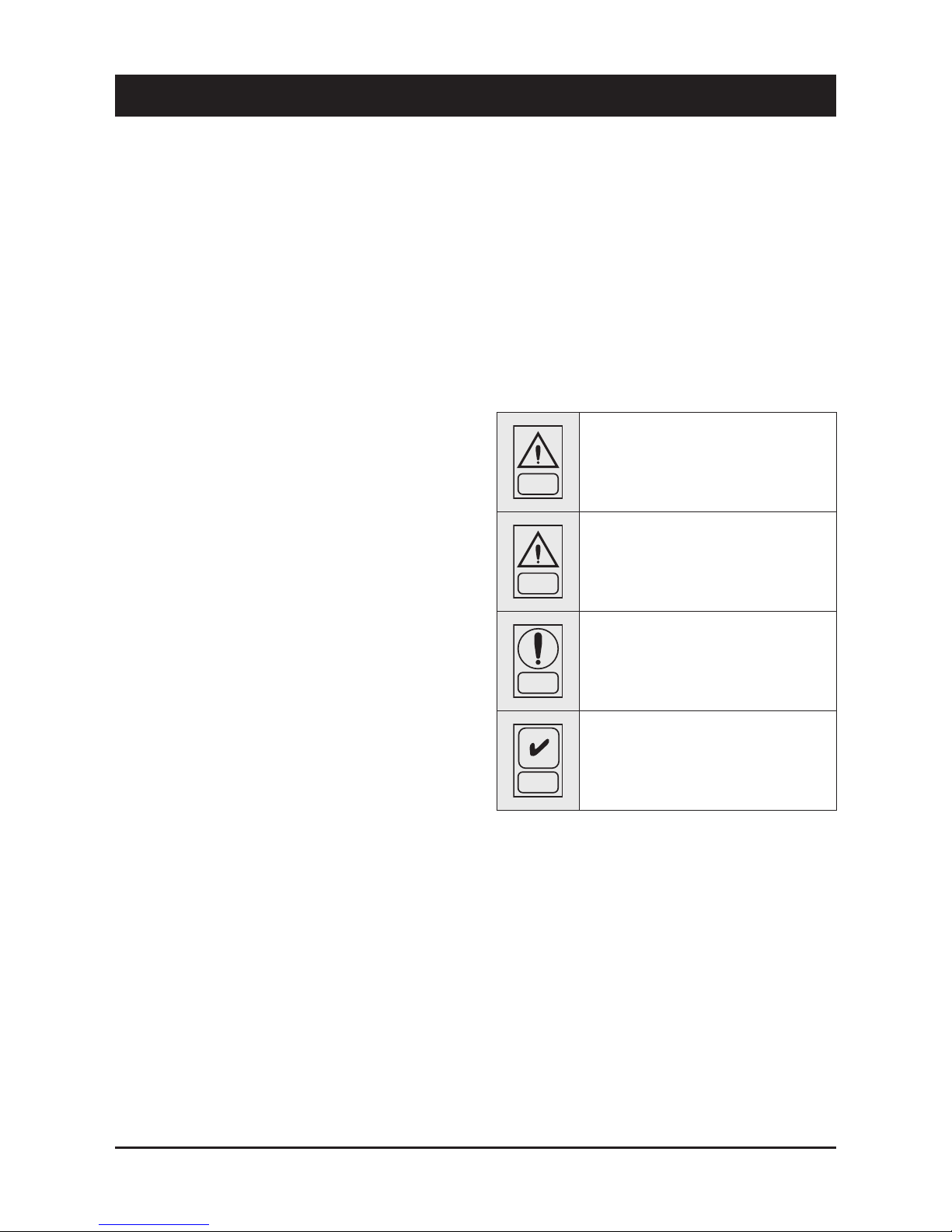
Conventions used throughout the manual:
DANGER
The DANGER sign recalls your attention to
a certain procedure or practice which, if not
followed, may result in serious damage to
people and property.
WARNING
The WARNING sign precedes those procedures
that, if not followed, may result in serious
damage to the appliance.
NOTE
The NOTE contain important observations.
USEFUL TIPS
The USEFUL TIPS provide valuable information
that optimises the efficiency of the appliance.
This manual and its contents, as well as the documentation which
accompanies the unit, are and remain the property of manufacturer,
which reserves any and all rights thereon. This manual may not
be copied, in whole or in part, without manufacturer’s written
authorization.
Page 5

3
English
2 - Safety
2.1 Foreword
These units must be installed in conformity with the
provisions of Machinery Directive 2006/42/EC, Low Voltage
Directive 2006/95/EC, Pressure Vessels Directive 97/23/
EC, Electromagnetic Interference Directive 2004/108/EC,
as well as with other regulations applicable in the country
of installation. If these provisions are not complied with, the
unit must not be operated.
DANGER
The unit must be grounded, and no
installation and/or maintenance operations
may be carried out before deenergising the
electrical panel of the unit.
Failure to respect the safety measures mentioned above may result
in electrocution hazard and fire in the presence of any short-circuits.
DANGER
Inside the heat exchangers, the compressors
and the refrigeration lines, this unit contains
liq u i d a n d g a se o u s r e fri g e ra n t u nd e r
pressure. The release of this refrigerant may
be dangerous and cause injuries.
DANGER
The units are not designed to be operated with
natural refrigerants, such as hydrocarbons.
Manufacturer may not be held liable for any
pr oblem s der iving from the repla cemen t
of original refrigerant or the introduction of
hydrocarbons.
Units are designed and manufactured according to the requirements
of European Standard PED 97/23/EC (pressure vessels).
! The used refrigerants are included in group II (non-hazardous
fluids).
! The maximum working pressure values are mentioned on the
unit’s data plate.
! Suitable safety devices (pressure switches and safety valves)
have been provided, to prevent any anomalous overpressure
inside the plant.
! The vents of the safety valves are positioned and oriented in such
a way as to reduce the risk of contact with the operator, in the
event that the valve is operated. Anyway, the installer will convey
the discharge of the valves far from the unit.
! Dedicated guards (removable panels with tools) and danger signs
indicate the presence of hot pipes or components (high surface
temperature).
DANGER
The guards of the fans (only for units provided
with air heat exchan gers) m ust be always
mounted and must never be removed before
de-energising the appliance.
DANGER
It is the User’s responsibility to ensure that
the unit is fit for the conditions of intended use
and that both installation and maintenance are
carried out by experienced personnel, capable
of resp e c t i n g all th e r e c o mmendati o n s
provided by this manual.
It i s i mportan t that th e unit is adequ ately
supported, as detailed in this manual. Noncompliance with these recommendations may
create hazardous situations for the personnel.
DANGER
The unit must rest on a base which meets the
characterist ics specified in this manual; a
base with inadequate characteristics is likely
to become a source of serious injury to the
personnel.
WARNING
Th e un it h a s no t be en de sign to w ithst and
loads and/or stress that may be transmitted by
adjacent units, piping and/or structures.
Each external load or stress transmitted to the
unit may break or cause breakdowns in th e
unit’s structure, as well as serious dangers to
people. In these cases, any form of warranty will
automatically become null and void.
WARNING
The packaging material must not be disposed of
in the surrounding environment or burnt.
Page 6

4
2 - Safety
2.2 Definitions
OWNER: means the legal representative of the company, body or
individual who owns the plant where unit has been installed; he/she
has the responsibility of making sure that all the safety regulations
specified in this manual are complied with, along with the national
laws in force.
INSTALLER: means the legal representative of the company who has
been given by the owner the job of positioning and performing the
hydraulic, electric and other connections of unit to the plant: he/she
is responsible for handling and properly installing the appliance, as
specified in this manual and according to the national regulations in
force.
OPERATOR: means a person authorised by the owner to do on unit
all the regulation and control operations expressly described in this
manual, that must be strictly complied with, without exceeding the
scope of the tasks entrusted to him.
ENGINEER: means a person authorised directly by manufacturer or,
in all EC countries, excluding Italy, under his full responsibility, by
the distributor of product, to perform any routine and extraordinary
maintenance operations, as well as any regulation, control, servicing
operations and the replacement of pieces, as may be necessary
during the life of the unit.
2.3 Access to the unit
The unit must be placed in an area which can be accessed also
by OPERATORS and ENGINEERS; otherwise the unit must be
surrounded by a fence at not less than 2 meters from the external
surface of the machine.
OPERATORS and ENGINEERS must enter the fenced area only
after wearing suitable clothing (safety shoes, gloves, helmet etc.).
The INSTALLER personnel or any other visitor must always be
accompanied by an OPERATOR.
For no reason shall any unauthorised personnel be left alone in
contact with the unit.
2.4 General precautions
The OPERATOR must simply use the controls of the unit; he must not
open any panel, other than the one providing access to the control
module.
The INSTALLER must simply work on the connections between plant
and machine; he must not open any panels of the machine and he
must not enable any control.
When you approach or work on the unit, follow the precautions listed
below:
! do not wear loose clothing or jewellery or any other accessory tat
may be caught in moving parts
! wear suitable personal protective equipment (gloves, goggles
etc.) when you have to work in the presence of free flames
(welding operations) or with compressed air
! if the unit is placed in a closed room, wear ear protection devices
! cut off connecting pipes, drain them in order to balance the
pressure to the atmospheric value before disconnecting them,
disassemble connections, filters, joints or other line items
! do not use your hands to check for any pressure drops
! use tools in a good state of repair; be sure to have understood the
instructions before using them
! be sure to have removed all tools, electrical cables and any other
objects before closing and starting the unit again
2.5 Precautions against residual risks
Prevention of residual risks caused by the control
system
!" be sure to have perfectly understood the operating instructions
before carrying out any operation on the control panel
! when you have to work on the control panel, keep always the
operating instructions within reach
! star t the unit only after you have checked its perfect connection
to the plant
! promptly inform the ENGINEER about any alarm involving the unit
! do not reset manual restoration alarms unless you have identified
and removed their cause
Prevention of residual mechanical risks
! install the unit according to the instructions provided in this
manual
! carry out all the periodical maintenance operations prescribed by
this manual
! wear a protective helmet before accessing the interior of the unit
! before opening any panelling of the machine, make sure that it is
secured to it by hinges
! do not touch air condensation coils without wearing protective
gloves
! do not remove the guards from moving elements while the unit is
running
! check the correct position of the moving elements’ guards before
restarting the unit
Prevention of residual electrical risks
! connect the unit to the mains according to the instructions
provided in this manual
! periodically carry out all the maintenance operations specified by
this manual
! disconnect the unit from the mains by the external disconnecting
switch before opening the electrical board
! check the proper grounding of the unit before star t-up
! check all the electrical connections, the connecting cables, and in
particular the insulation; replace worn or damaged cables
Page 7

5
English
2 - Safety
! periodically check the board’s internal wiring
! do not use cables having an inadequate section or flying
connections, even for limited periods of time or in an emergency
Prevention of other residual risks
! make sure that the connections to the unit conform to the
instructions provided in this manual and on the unit’s panelling
! if you have to disassemble a piece, make sure that it has been
properly mounted again before restarting the unit
! do not touch the delivery pipes from the compressor, the
compressor and any other piping or component inside the
machine before wearing protective gloves
! keep a fire extinguisher fir for electrical appliances near the
machine
! on the units installed indoor, connect the safety valve of the
refrigeration circuit to a piping network that can channel any
overflowing refrigerant outside
! remove and leak of fluid inside and outside the unit
! collect the waste liquids and dry any oil spillage
! periodically clean the compressor compartment, to remove any
fouling
! do not store flammable liquids near the unit
! do not disperse the refrigerant and the lubricating oil into the
environment
! weld only empty pipes; do not approach flames or other sources
of heat to refrigerant pipes
! do not bend/hit pipes containing fluids under pressure
2.6 Precautions during maintenance operations
Maintenance operations can be carried out by authorised technicians
only.
Before performing any maintenance operations:
! disconnect the unit from the mains with the external disconnecting
switch
! place a warning sign “do not turn on - maintenance in progress”
on the external disconnecting switch
! make sure that on-off remote controls are inhibited
! wear suitable personal protective equipment (helmet, safety
gloves, goggles and shoes etc.)
To carry out any measurements or checks which require the
activation of the machine:
! work with the electrical board open only for the necessary time
! close the electrical board as soon as the measurement or check
has been completed
! for outdoor units, do not carry out any operations in the presence
of dangerous climatic conditions (rain, snow, mist etc.)
The following precautions must be always adopted:
! do not scatter the fluids of the refrigeration circuit in the
surrounding environment
! when replacing an eprom or electronic cards, use always suitable
devices (extractor, antistatic bracelet, etc.)
! to replace a compressor, the evaporator, the condensing coils or
any other weighty element, make sure that the lifting equipment is
consistent with the weight to be lifted
! in air units with independent compressor compar tment, do not
access the fan compar tment unless you have disconnected the
machine by the disconnecting switch on the board and you have
placed a warning sign “do not turn on - maintenance in progress”
! contact manufacturer for any modifications to the refrigeration,
hydraulic or wiring diagram of the unit, as well as to its control
logics
! contact manufacturer if it is necessary to perform very difficult
disassembly and assembly operations
! use only original spare parts purchased directly from manufacturer
or the official retailers of the companies on the recommended
spare parts list
! contact manufacturer if it is necessary to handle the unit one year
after its positioning on site or if you wish to dismantle it.
Page 8
6
2 - Safety (continued)
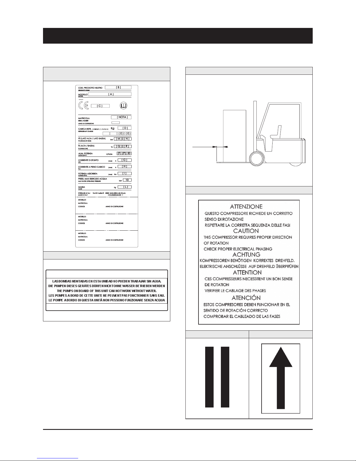
2.7 Safety labels
Identification of the unit Outside,
on the left -hand front column
Pump operation - Outside, on the left-hand front column
Instruction for the movimentation - Outside the packaging
Sequence phase control on the electrical board
Gravity centre - Base Instruction for the lifting
TENERE SU QUESTA LINEA
GANCIO DI SOLLEVAMENTO
KEEP LIFT HOOK
ON THIS LINE
MIN. 5 cm
Page 9
7
English
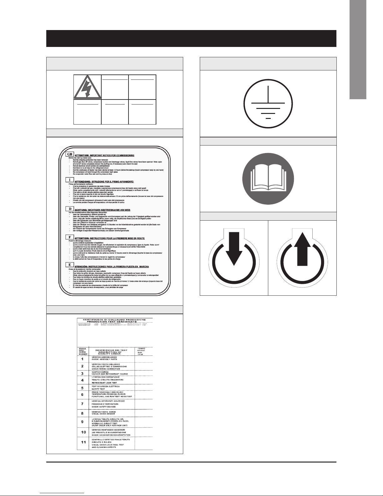
2 - Safety (continued)
Grounding connection on the electrical board,
adjacent to the connection
Read the instruction on the electrical board
Fitting identification - Adjacent to fittings
Electrical warning
Adjacent to the master switch
ATTENZIONE !
Prima di
aprire togli ere
tensione
CAUTION !
Disconnect
electrical
supply befor e
opening
ACHTUNG !
Vor offn en des
gehauses
hauptschalte r
ausschalten
ATENCION !
Cor tar la
corrente ant es
de abrir
el aparato
ATTENTION !
Enlever
l’alimentati on
electrique
avant d’ouvr ir
Commissioning - Outside, on the left-hand front column
Final Test Certificate - Inside the external door
Page 10
8
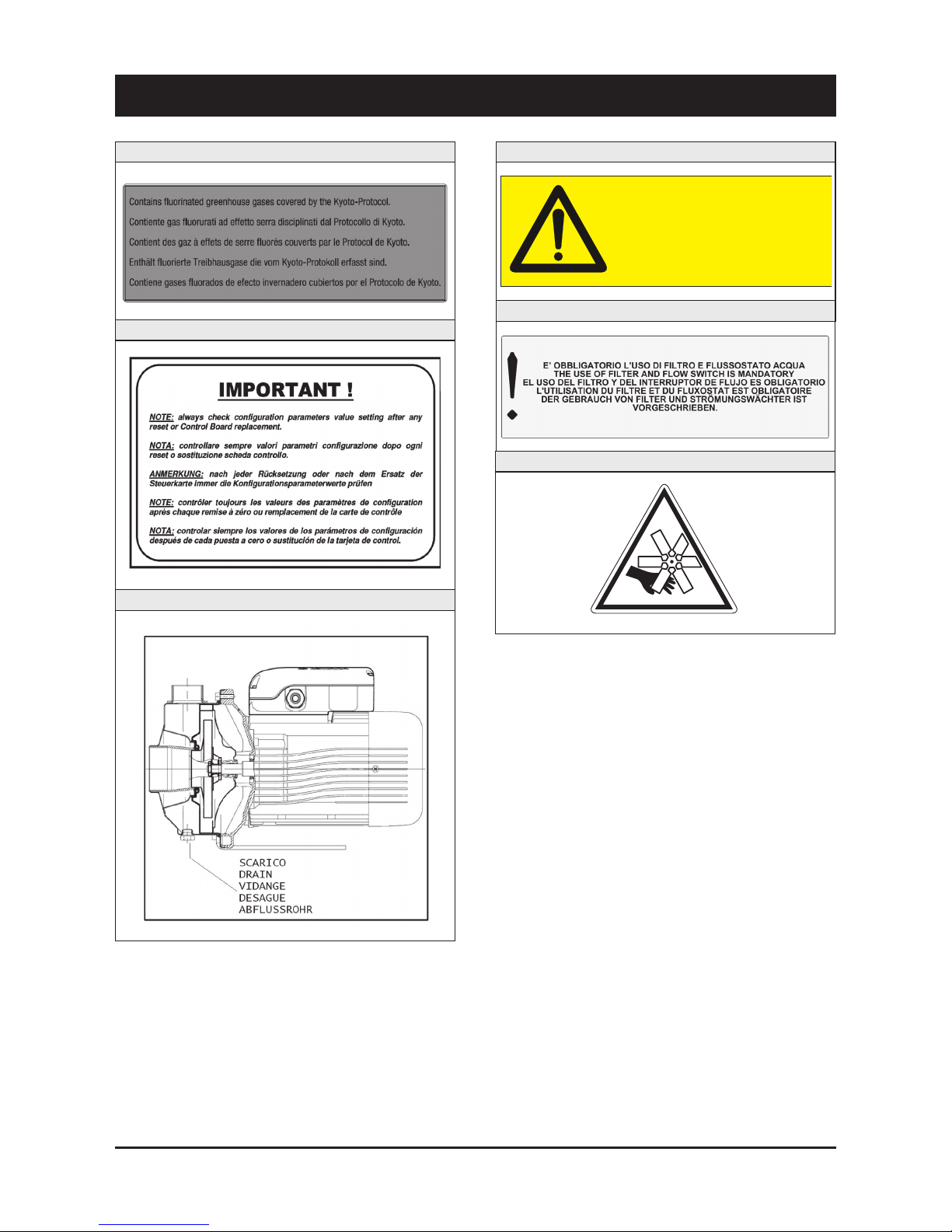
Fan Danger
2 - Safety (continued)
Identification of refrigerant - Below identification of the unit
Parameter configuration - Inside the electrical board
Pump drain - Outside, on the left-hand front column
Circuit drain - Outside, on the left-hand front column
Filter / flow switch - Outside, on the left-hand front column
ATTENTION! Don’t leave the unit with water inside hydraulic circuit during
winter or when it is in stand by.
ATTENZIONE! Non lasciare l’unità con acqua nel circuito idraulico durante
l’inverno o quando non è funzionante.
ATTENTION! Ne laissez pas l’unitè avec de l’eau dans le circuit hydraulique
pendant l’hiver ou quand elle ne travaille pas.
WARNUNG! Lassen Sie nicht das Wasser in die Schaltung während des
Winters oder wenn es nicht funktionient.
¡ATENCÍON! No deje el agua en el circuito hidráulico durante el invierno o
cuando no esta trabajando.
Page 11
9
English
2 - Safety
REFRIGERANT DATA SAFETY DATA: R410A
Toxicity Low.
Contact with skin
If sprayed, the refrigerant is likely to cause frost burns. If absorbed by the skin, the danger is very limited;
it may cause a slight irritation, and the liquid is degreasing. Unfreeze the affected skin with water.
Remove the contaminated clothes with great care - in the presence of frost burns, the clothes may stick
to the skin. Wash with plenty of warm water the affected skin.
In the presence of symptoms such as irritation or blisters, obtain medical attention.
Contact with eyes
Vapours do not cause harmful effects. The spraying of refrigerant may cause frost burns.
Wash immediately with a proper solution or with tap water for at least 10 minutes, and then obtain
medical attention.
Ingestion
Very unlikely - should something happen, it will cause frost burns.
Do not induce vomiting. Only if the patient is conscious, wash out mouth with water and give some
250 ml of water to drink. Then, obtain medical attention.
Inhalation
R410A: remarkable concentrations in the air may have an anaesthetic effect, up to fainting.
The exposure to considerable amounts may cause irregular heartbeat, up to the sudden death of the
patient. Very high concentrations may result in the risk of asphyxia, due to the reduction in the oxygen
percentage in the atmosphere. Remove the patient to fresh air and keep warm and at rest.
If necessary, give oxygen. In case of breathing difficulties or arrest, proceed with artificial respiration.
In case of cardiac arrest, proceed with cardiac massage. Then, obtain medical attention.
Recommendations
Semiotics or support therapy is recommended. Cardiac sensitisation has been observed that, in
the presence of circulating catecholamines such as adrenalin, may cause cardiac arrhythmia and
accordingly, in case of exposure to high concentrations, cardiac arrest.
Prolonged exposure
R410A: a study on the effects of exposure to 50,000 ppm during the whole life of rats has identified the
development of benign testicle tumour.
This situation should therefore be negligible for personnel exposed to concentrations equal to or lower
than professional levels.
Professional levels R410A: Recommended threshold: 1000 ppm v/v - 8 hours TWA.
Stability R410A: Not specified.
Conditions to avoid Do not use in the presence of flames, burning surfaces and excess humidity.
Hazardous reactions
May react with sodium, potassium, barium and other alkaline metals.
Incompatible substances: magnesium and alloys with magnesium concentrations > 2%.
Hazardous decomposition
products
R410A: Halogen acids produced by thermal decomposition and hydrolysis.
2.8 Safety regulations
Page 12
10
2 - Safety
REFRIGERANT DATA SAFETY DATA: R410A
General precautions
Do not inhale concentrated vapours. Their concentration in the atmosphere should not exceed the
minimum preset values and should be maintained below the professional threshold. Being more weighty
than the air, the vapour concentrates on the bottom, in narrow areas. Therefore, the exhaust system must
work at low level.
Respiratory system protection
If you are in doubt about the concentration in the atmosphere, it is recommended to wear a respirator
approved by an accident-prevention
Authority, of the independent or oxygen type.
Storage
Cylinders must be stored in a dry and fresh place, free from any fire hazard, far from direct sunlight or
other sources of heat, radiators etc.
Keep a temperature below 50 °C.
Protective clothing Wear overalls, protective gloves and goggles or a mask.
Accidental release measures
It is important to wear protective clothing and a respirator.
Stop the source of the leak, if you can do this without danger. Negligible leaks can be left evaporating
under the sun, providing that the room is well ventilated.
Considerable leaks: ventilate the room. Reduce the leak with sand, earth or other absorbing substances.
Make sure that the liquid does is not channelled into gutters, sewers or pits where the vapours are likely
to create a stuffy atmosphere.
Disposal
The best method is recovery and recycling. If this method is not practicable, dispose according to an
approved procedure, that shall ensure the absorption and neutralization of acids and toxic agents.
Fire fighting information R410A: Not flammable in the atmosphere.
Cylinders The cylinders, if exposed to fire, shall be cooled by water jets; otherwise, if heated, they may explode.
Protective fire fighting equipment In case of fire, wear an independent respirator and protective clothing.
2.8 Safety regulations (continued)
Page 13
11
English
2 - Safety
LUBRICANT OIL DATA SAFETY DATA: POLYESTER OIL (POE)
Classification Not harmful.
Contact with skin
May cause slight irritation. Does not require first aid measures. It is recommended to follow usual
personal hygiene measures, including washing the exposed skin with soap and water several times a day.
It is also recommended to wash your overalls at least once a week.
Contact with eyes Wash thoroughly with a suitable solution or tap water.
Ingestion Seek medical advice immediately.
Inhalation Seek medical advice immediately.
Conditions to avoid
Strong oxidising substances, caustic or acid solutions, excess heat.
May corrode some types of paint or rubber.
Protection of the
respiratory system
Use in well ventilated rooms.
Protective clothing
Always wear protective goggles or a mask. Wearing protective gloves is not mandatory, but is
recommended in case of prolonged exposure to refrigerant oil.
Accidental release measures
It is important to wear protective clothing and, especially, goggles.
Stop the source of the leak. Reduce the leak with absorbing substances (sand, sawdust or any other
absorbing material available on the market).
Disposal
The refrigerant oil and its waste will be disposed of in an approved incinerator, in conformity with the
provisions and the local regulations applicable to oil waste.
Fire fighting information
In the presence of hot liquid or flames, use dry powder, carbon dioxide or foam. If the leak is not burning,
use a water jet to remove any vapours and to protect the personnel responsible for stopping the leak.
Cylinders The cylinders exposed to a fire will be cooled with water jets in case of fire.
Fire fighting protective equipment In case of fire, wear an independent respirator.
2.8 Safety regulations (continued)
Page 14
12
3 - Transport, Handling and Storage
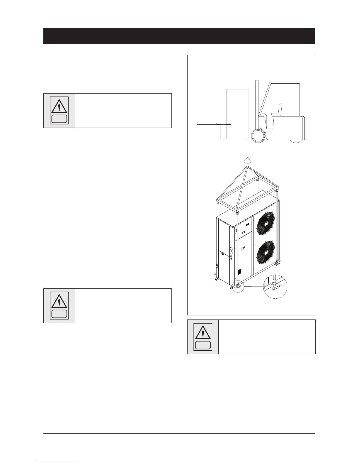
MIN. 5 cm
Space requirements request to handling
Holes Ø 30 mm
WARNING
While lifting and handling the unit, pay attention.
Otherwise, you might damage the finned block of
the coils arranged on both sides of the unit. The
sides of the unit shall be protected by cardboard
or plywood sheets.
Units are supplied fully assembled and tested (except for accessories
supplied loose in the units – absorbers, filter, etc.). They are ready to
be installed and started on the field.
R410A units are only charged with liquid refrigerant and with oil in the
quantity required for operation.
WARNING
The low pressure side of the refrigerating circuit
on R410A units sh all be charged b y means
of the service valve arranged on the thermal
expansion valve before the device is operated.
3.1 Inspection
The unit shall be immediately inspected upon receipt to find out any
damage since it has been delivered ex works and transported at the
customer’s risk. It is also necessary to make sure that all the parcels
specified on the delivery note have been delivered.
Any damage you may find out shall be immediately reported in writing
to the carrier. Even if the damage is only on the surface, please notify
our local representative too.
The manufacturer disclaims all responsibility for the shipment even if
it has provided for its organisation.
3.2 Handling
Units are designed to be lifted from above, by means of cables and
eyebolts. A spacer shall be arranged between the cables in order to
prevent them from damaging the unit (see the figure aside).
Before handling the devices, make sure the site you have chosen for
the installation can withstand its weight and suppor t its mechanical
impact.
Avoid touching sharp parts (such as the fins of batteries, for example)
while handling the unit.
WARNING
The unit shall never be placed on rollers.
Act as follows to lift and handle the unit:
!"
Insert and secure the eyebolts into the frame holes which have
been marked on purpose.
!"
Connect the cables to the eyebolts.
!"
Insert the spacer between the cables.
!"
Provide for hooking at the centre of gravity of the device.
!"
Cables shall have such a length that the angle they form with the
horizon when under tension is not less than 45°.
Page 15

13
English
3 - Transport, Handling and Storage
WARNING
Until the unit i s r eady f or ope ration, do not
re m o v e t h e p l a s t i c e n v e l o p e a n d t h e c o i l
protections which are intended to prevent dirt,
dust and any foreign matter from penetrating
into the unit through the inlets of fans or from
damaging the external surfaces.
3.3 Anchoring
It is not essential to secure the unit to the foundations, unless in areas
where there is a serious risk of ear th-quake, or if the appliance is
installed on the top of a steel frame.
3.4 Storage
If the unit is to be stored before the installation for some time, take
at least the following precautions to prevent damage, corrosion and/
or deterioration:
!"
Make sure all openings, such as for example water connections,
are well plugged and sealed.
!"
Never store the units in a room where temperature is above
50 °C (R410A units) or where the units are directly exposed to
the sunlight.
!"
Minimum storage temperature is -25 °C.
!"
It is recommended to leave the finned coils covered to protect
them against any risk of corrosion, especially if building works
are still in progress.
!"
Store the units in areas where minimum activity is likely to take
place in order to avoid any risk of accidental damage.
!"
Never use steam to clean the unit.
!"
Remove all the keys required to have access to the control panel
and give them to the person in charge of the field.
It is also recommended to provide for visual inspections at regular
intervals.
Page 16

14
4 - Installation
4.1 Installation Site
DANGER
Before installing the unit, make sure that
the building structure and/or the supporting
surfac e can wit hstan d the wei ght of the
device. The weights of the units are detailed
by Chapter 9 of this manual.
These units have been designed to be installed on the floor, in the
open air. As a standard, they are equipped with rubber vibrationdamping supports which shall be arranged in the middle, beneath
the supporting plates.
When the unit is to be installed on the ground, provide for a concrete
bedplate which shall assure a uniform distribution of the weights. No
special subbase is generally required.
When selecting the installation site, never forget to consider as
follows:
!
The longitudinal axis of the unit shall be parallel to the direction of
the prevailing winds so as to assure a uniform air distribution on
finned exchangers.
!
The unit shall never be installed in the proximity of chimneys for
the discharge of boiler flue gases.
!
The unit shall never be installed downwind of sources of grease
contaminated air, such as for example the outlets of largekitchen extractors. Otherwise, grease might build up on the fins
of refrigerant / air exchangers or condensers, act as a fixing
agent for any sor t of atmospheric impurity and rapidly cause the
exchangers to clog.
!
The unit shall never be installed in areas exposed to heavy
snowfalls.
!
The unit shall never be installed in areas exposed to flooding or
beneath drip stones, etc.
!
The unit shall never be installed in narrow inner cour t yards or in
any other restricted space where the noise may be reflected by
the walls or where the air expelled by the fans may short-circuit
on the refrigerant/air heat exchangers or condensers.
!
The installation site shall be characterised by the presence of
the space required for air circulation and for the performance of
maintenance operations (see chapter 9 for further details).
4.2 External Water Circuit
WARNING
The external water circuit shall guarantee a
constant water flow rate through the circulating
refrigerant/water heat exchanger (evaporator)
under steady operating conditions and in case
of a load variation.
The circuit shall be composed by the following elements:
!
A circulation pump which can ensure the necessary flow rate and
head.
!
The total content of the primary water circuit shall never be
lower than 4 lt/kW in terms of refrigerating capacity. If the total
water volume in the primary circuit should be unable to reach
such a value, an additional heat-insulated storage tank should be
installed. This tank is intended to avoid any repetitive start of the
compressor.
!
A membrane expansion tank complete with a safety valve and a
drain which shall be visible.
NOTE
The expansion tank shall be dimensioned in
such a way that it can absorb a 2% expansion
of the total volume of the water in the plant
(exchanger, pipelines, uses and storage tank,
if available). The expansion tank shall never
be insulated when the circulating fluid is not
flowing through it.
A differential pressure switch is mounted as a standard. It will stop
the unit whenever it senses a load loss through the heat exchanger
which may result in a flow rate problem.
In addition:
!
Install on/off valves (accessory) on the lines at the inlet and outlet
of the manifolds of the exchangers (evaporator).
!
Arrange a by-pass complete with an on/off valve between the
manifolds of the heat exchangers.
!
Arrange air vent valves at the high points of the water lines.
!
Arrange drain points complete with plugs, clocks, etc. in the
proximity of the low points of the water lines.
!
Insulate the water lines to prevent the heat from blowing back into
the unit.
Page 17

15
English
External water circuit SYSCROLL 20-35 Air CO/HP - R410A
4 - Installation
SAFETY/CONTROL DEVICES
A Inlet water temperature sensor
B Outlet water temperature sensor
C Water differential pressure switch (105 mbar)
D Vent valve
E Water safety valve (3 bar)
F Manometer
FS Flow switch
G Thermometer
Unit side
Y Water drain
10
10
9 9
13
12
12 11
11
4
5
3
8
6
HYDROKIT
INLET
OUTLET
Y
2
1
7
FS
F
E
E
D
D
C
A
B
G
G
COMPONENTS
1 Plate heat exchanger
2 Pump
3 Draining valve
4 Water buffer tank
5 Water filter
6 Automatic water charging valve
7 Pressure expansion tank
8 Water charging line
9 Water outlet
10 Water inlet
11 Globe valve
12 Flexible pipes
13 By-pass valve
Page 18

16
4 - Installation
WARNING
Before filling the installat ion, remove any
impurity, such as sand, crushed stones and
welding scales, coating drops and any other
material which might damage the evaporator.
It is advisable to flush with disposable water bypassing the exchanger
to avoid clogging.
NOTE
The water used to fill the circuit shall be treated
in such as way that the pH will have the correct
value.
When two or several units are connected in parallel, to balance the
load losses of the various circuits, it is recommended to execute a
“reverse return” connection (see the diagram below).
UNIT 1
UNIT 2
Legend
S On/Off valves
VG Balancing valves
4.3 Water connections
The flow switch and the filter water, although not included in the
supply, must always be fitted such as plant components.
Their installation is mandatory for warranty.
WARNING
The attachments at the water inlet and outlet
shall be connected in compliance with the
instructions which can be found on the labels in
the proximity of the attachments.
Connect the water lines of the plants with the attachments of the unit
whose diameters and positions are shown in Chapter 9.
4.4 Defrost water drainage
(only for SYSCROLL Air HP units)
When SYSCROLL Air HP heat pump units work in heating mode,
during defrosting cycles, they may discharge water from the base.
This is why the units should be installed at least 200 mm above the
floor level, so as to allow the free drainage of waste water, without the
risk of producing ice banks.
The SYSCROLL Air HP heat pump units must be installed in positions
where the defrosting water cannot create any damage.
4.5 Water buffer tank
The accumulation tank which has been designed to be mounted
on SYSCROLL Air HP units is complete with all the hydraulic and
electrical components required for the correct operation of the
system.
These systems are carefully assembled and tested at works. They
are ready for operation after having correctly realised all electrical
and hydraulic connections.
4.5.1 Features
The kit will include an Antifreeze Electric Heater, a drain valve, an
automatic filling unit and an automatic air vent.
No pump is arranged on the kit since it is mounted on the unit.
A tank arranged for mounting a heating booster resistance kit may be
optionally required (5 traps).
The tank is completely insulated with 30 Kg/m3 closed cell
polyethylene in a silver colour and enclosed by a bearing structure
made of passivated and painted plates. The box is equipped with
bulkheads which can be easily opened for internal inspection.
The kit is installed beneath the chiller. It is an integral part of the unit
without changing the support area.
4.5.2 Supplied Material
The kits will be supplied with pipelines ready for installation. An
antifreeze resistance with wiring, an automatic water filling valve, a
3 bar safety valve, a drain valve and a vent valve have already been
assembled.
Hydrokit is shipped with a film to protect it from atmospheric agents.
Packaging has been designed in order to stack it up.
4.5.3 Antifreeze Electric Heater
The antifreeze resistance of the tank (TEH) shall be wired with the
panel as it is shown by the diagram attached to the unit.
4.5.4 Water Filter
The kit will use the water filter of the unit.
Page 19

17
English
4.6 Power supply
DANGER
Befo re carrying out any op erations on the
electrical system, make sure that the unit is
deenergized.
DANGER
It is important that the appliance is grounded.
WARNING
The company in charge of the installation shall
conform to the standards applicable to outdoor
electrical connections.
The manufacturer may not be held liable for any damage
and/or injury caused by failure to comply with these
precautions.
The unit conforms to EN 60204-1.
The following connections shall be provided:
!
A 3-phase and grounding connection for the power supply circuit.
!
The electrical distribution system shall meet the power absorbed
by the appliance.
!
The disconnecting and magnetothermal switches must be sized
to control the starting current of the unit.
!
The power supply lines and the insulation devices must be
designed in such a way that every line independent.
!
It is recommended to install differential switches, to prevent any
damage caused by phase drops.
!
The fans and compressors are supplied through contactors
controlled from the control panel.
!
Each motor is provided with an internal safety thermal device and
external fuses.
!
The power supply cables must be inser ted into dedicated
openings on the front of the unit, and the will enter the electrical
board through holes drilled on the bottom of the board.
4 - Installation
CAUTIONS
The unit + tank system shall be equipped with a filter. Use the filter
+ union as it is shown by Figure 1.
Figure 1
4.5.5 Installation Procedure
For the size 20-35 the hydrokit shall be arranged beneath the unit. It
will not change its overall dimensions (Figure 1).
Arrange the rubber shock absorbers beneath the kit before providing
for its connection.
Provide for the hydraulic and electrical connections. Doing that,
observe the diameters shown by the quoted drawings.
The wiring for the standard antifreeze resistance is arranged as it is
shown by . The resistance is connected with the main terminal box.
See the wiring diagram attached to the unit for the correct execution
of the electrical connections.
Install the water filter as it is shown by Figure 1.
Page 20

18
Antifreeze
Resistance Wiring
4 - Installation
4.7 Electrical connections
The unit must be installed on site according to the usual
procedures and standards applicable in the place of
installation. The unit must not be operated if its installation
has not been carried out according to the instructions
provided in this manual.
The power supply lines must consist of insulated copper
conductors, dimensioned for the maximum absorbed
current.
Connection to terminals must be performed according to the diagram
of connections (User’s Terminal Box) provided in this manual and
according to the wiring diagram which accompanies the unit.
WARNING
Before connecting the power supply lines, check
that the available voltage value does not exceed
the range specified in the Electric Data (Chapter
9).
For 3-phase systems, check also that the unbalance between the
phases does not exceed 2%. To perform this check, measure the
differences between the voltage of each phase couple and their mean
value during operation. The maximum % value of these differences
(unbalance) must not exceed 2% of the mean voltage.
If the unbalance is unacceptable, contact the Energy Distributor to
solve this problem.
WARNING
Supplyi n g the u n i t throug h a line w h o s e
unbalance exceeds the permissible value will
automatically void the warranty.
Page 21

19
English
SYSCROLL Air CO/HP Version - Electrical Connections
4 - Installation
Page 22

20
5 - Start-up
WARNING
The unit must be started for the first time by
personnel suitably trained by one of Authorised
Service Centre. Failure to meet this requirement
will immediately void the warranty.
NOTE
Th e o p e r a t i ons carried out by a u t h o r i s e d
perso nnel ar e l imit ed to the start-u p of the
unit, and do not include any other operation
on the plant, such as, for example, electrical
and hydraulic connection s etc. All the other
operations before start-up, including oil preheating for at least 12 hours, must be performed
by the Installer.
5.1 Preliminary check
The checks listed below shall be performed before starting the unit
and before the arrival of the personnel authorised.
!
Check the section of power supply and grounding cables; make
sure that terminals are tightened and check the correct operation
of contactors, with the main switch open.
!
Check that any voltage and phase variation in the power supply
does not exceed the prefixed thresholds.
!
Connect the contacts of the flow switch and of an external
interlock, to terminals 1-2 and 3-4 (Y1 user terminal), respectively.
!
Check that the components of the external water circuit (pump,
user equipment, filters, power supply tank and reservoir, if any)
have been installed properly, and according to the manufacturer’s
instructions.
!
Check the filling of the hydraulic circuits, and make sure that
the fluid circulation is correct, without any trace of leaks and air
bubbles. If you use ethylene glycol as antifreeze, check that its
percentage is correct (do not exceed 35% glycol percentage).
!
Check that the direction of rotation of the pumps is correct, and
that fluids have been circulating for at least 12 hours for both
pumps. Then, clean the filters on the suction side of the pumps.
!
Adjust the liquid distribution network in such a way that the flow
rate is within the specified range.
!
Check that the water quality is up to the specifications.
!
Check that oil heaters, if any, have been turned on at least 12 hours
before.
5.2 Start-up
Start-up sequence:
!
Turn on the Main switch (at least 12 hours before).
!
Check that the oil in the compressor has reached the requested
temperature (the minimum temperature outside the pan must be
approx. 40°C) and that the auxiliary control circuit is energised.
!
Check the operation of all the external equipment, and make sure
that the control devices of the plant are properly calibrated.
!
Star t the pump and check that the water flow is correct.
!
Set the desired fluid temperature on the control board.
!
Star t the appliance (see Chapter 6).
!
Check the correct direction of rotation of compressors. Scroll
compressors cannot compress the refrigerant when they rotate in
the opposite direction. To make sure that they are rotating in the
correct direction, simply check that, just after the star t-up of the
compressor, the pressure drops on the LP side and rises on the
HP side. Fur thermore, if a scroll compressor rotate in the opposite
direction, there is a considerable rise in the sound level of the unit,
as well as in a dramatic reduction of current absorption compared
to normal values. In case of wrong rotation, the scroll compressor
can be definitely damaged. Phase monitor is assembled in the
unit as a standard to prevent wrong compressors rotation.
!
After about 15 minutes of operation check that there are no
bubbles, through the sight glass on the liquid line.
WARNING
The presence of bubbles may indicate that a
part of the refrigerant charge has been released
in one or more points. It is important to remove
these leaks before proceeding.
!
Repeat the start-up procedure after removing the leaks.
5.3 Checking the operation
Check the following:
!
The temperature of the water entering the evaporator.
!
The temperature of the water leaving the evaporator.
!
The level of the water flow rate in the evaporator, if possible.
!
The current absorption upon the start of the compressor and in
case of stabilised operation.
!
The fan’s current absorption.
Check that the condensing and evaporation temperatures, during
operation at high and low pressure detected by the pressure gauges
of the refrigerant, are within the following range :
(On the units not provided with HP/LP pressure gauges for the
refrigerant, connect a pressure gauge to the Shrader valves on the
refrigeration circuit).
HP side
Approx. 15 to 20 °C above the temperature of the
air entering the condenser, for R410A units.
LP side
Approx. 2 to 4 °C below the temperature of the
leaving chilled water, for R410A units.
5.4 Delivery to the customer
!
Train the user according to the instructions provided in Section 6.
Page 23

21
English
6 - Control
6 General information
Introduction
This document contains the information and the operating
instructions.
Main characteristics
– simple user interface with possibility to customize keys functions
and to set menus visibility
– parameter setting through keyboard or PC
– thermoregulation" #" inlet/outlet water probe, according to
customer need / application
– auto-adaptive set-point
– dynamic set-point
– sanitary hot water and anti-legionella weekly scheduling
– alarm log
– analogue input (to be set)"#"NTC, 4..20mA, 0..1V, 0..5V, 0..10V
– digital input"#"to be set by parameter
– automatic changeover
– analogue condensation control
– boiler / electrical resistances management for heating
integration
– electrical resistance management for sanitary hot water
– advanced pump management
The following accessories can be also connected:
– multi Function Key (MFK) to upload / download parameters map
– serial communication RS485 card; to connect the control to a
BMS network
– remote display terminal
– wire remote control
6.1 Control of a single compressor unit
Units are provided with a microprocessor card fully programmed by
default for the control of a heat pump unit.
General information
The figure shows the terminal. It is provided with a 4 red digits with
7 segments with decimal point led, 18 LED and 4 buttons, so as
to allow the programming of the control parameters (setpoint,
differential bands, alarm thresholds) and the main operations to be
carried out by the user.
6.2 Keypad functions
KEY
LINKED
FUNCTION
KEYS
COMBINATION
DESCRIPTION
EXTENDED PUSH
(MORE THAN 3s)
LINKED FUNCTION
UP
DOWN
ESC
SET
SINGLE PUSH
(PUSH /RELEASE)
MENU/NOTES
MENU/NOTES
- Increase value
- Go to next label
- Change Set-point
- Enable Sanitary Hot Water
function
- Enable / Disable
/
/
/
/
- Decrease value
- Go to previous label
- Change Set-point (if UI25 =1)
- Stand-by
- Local ON/OFF
- Time slots menu
- Stand-by # ON
- Enter in “Program Menu” - Program Menu
- Exit without saving
- Go to previous level
- Mode menu- Change mode
- Confirm value / exit with setting
saving
- Go to next level
- Go to status menu
- Display menu- Main display
Page 24

22
6 - Control (continued)
ICON / COLOR STEADY ICON BLINKING ICON
- Alarm ON/ RED
/ GREEN
/ GREEN
/ GREEN
/ GREEN
/ GREEN
/ RED
/ RED
/ RED
/ RED
/ RED
- Mode: HEATING
- Current HR
- Time slots activ.
- Mode: COOLING
/
/
/
- Mode: STAND-BY
- Configurable
Not used
Menu surf
- Alarm QUIT
- Antifreeze+Heat pump ON
- Heating mode by remote
- HR setting
- Time slots programming
- Cooling mode by remote
/
/
/
- Stand-by mode by remote
- Configurable
Not used
/
6.3 Folder structure
Folder structure is composed of totally four menus
1) Main display"#"used to set what to display without acting on any
key
– Ai"#"analogue input (temperature, pressure)
– rtC"#"room time clock
– SetP"#"standard set-point
– SetR"#"corrected set-point (according to climatic correction,
etc.)
2) Operating mode"#"used to set operating mode
– StbY"#"stand-by
– HEAT"#"heating
– COOL"#"cooling
– AS"#"sanitary hot water
3) Status"#"used to show resources values
– Ai (AIL/AIE/Air)"#"analogue inputs (main board / expansion
board / remote terminal)
– di (diL/diE)"#"digital inputs (main board / expansion board)
– AO (AOL/AOE)"#" analogue outputs (main board/expansion
board)
– CL (HOUr/dAtE/YEAr)"#"clock
– AL (Er00"#"Er98)"#"alarms
– SP"#"standard set-point
– Sr" #" corrected set-point (according to climatic correction,
etc.)
4) Program"#"define parameters, functions, password and to display
alarm log
6.4 Menu structure
“Program” menu is composed of totally four folders
1) Parameters"#"change unit parameters
2) Functions"#"manual operations (switch ON / switch OFF, alarm
quit, historic alarm delete, multi function key use)
3) Password"#"define visibility levels for parameters/folders
4) Alarm log"#"display alarm log
Parameter folder gives access to following sub-folders
– CL/CE/Cr/CF"#"configure device I/O (L"#"local; E"#"expansion; r "
#"remote; F"#"serial)
!" #$#%&'()" *$+(,-" .,/+)" &0" +1&2)3" 1#$')3" 4*00)1)$,*#%3" %&'*5"
function)
!" 4*'*,#%"*$+(,-".%&'*5"0($5,*&$6
!"" 4*'*,#%"&(,+(,-".%&'*5"0($5,*&$6" "
!"" #$#%&'()"&(,+(,-".1#$')6
!"" -)1*#%"5&$0*'(1#,*&$".5&77($*5#,*&$"+#1#7),)1-6"
– TR"#"define thermoregulation parameters
!"" -),8+&*$,".7#9:7*$:;/-,)1)-*-6" "
!"" ,/+)".+1&+&1,*&$#%:4*00)1)$,*#%6" "
!"" +1&2)"-)%)5,*&$"" "
– ST"#"define operating status
!"" 5&&%*$'"&$%/""
!"" ;)#,*$'"&$%/" "
!"" -5&&%*$'"#$4";)#,*$'""" "
!"" 5;#$')8&<)1""
– CP"#"configure compressor parameters (type/number/timing)
– PI"#"define primary circuit / source side circuit pump parameters
/ functions
!"" &+)1#,*$'"7&4)".4*-#2%)":"#%=#/-">?":">?"*0"5&7+1)--&1">?6
!"" 4*'*,#%":"#$#%&'()"5&$,1&%" "
!"" #$,*8-,*5@*$'""
!"" #$,*801))A)" "
– BR " #" control the parameters for an additional step for heating
and for sanitary hot water integration (boiler)
!"" &+)1#,*$'"7&4)".4*-#2%)":"4*00)1)$,*#%""#" fixed or in function of
outdoor air temperature)
!"" -),8+&*$,":";/-,)1)-*-" "
– DS"#"define set-point offset (dynamic set-point) depending on
!"" #$#%&'()"*$+(,".BCDE3"BCFE3"BCDBE3"GCHB7I6"
!"" &(,4&&1"#*1",)7+)1#,(1)""
!"" 1&&7",)7+)1#,(1)" "
– AD"#" simulate an electronic inertial accumulator, acting on set-
point and hysteresis (adaptive function), by confronting minimum
/ effective ON-OFF time
– AS"#"define sanitary hot water management parameters
!"" &+)1#,*$'"7&4)".4*-#2%)":"-#$*,#1/";&,"=#,)1"<#%<)":"1)-*-,#$5)"
/ pump)
!"" -),8+&*$,":";/-,)1)-*-" "
!"" #$,*8%)'*&$)%%#"0($5,*&$" "
– HP"#"define heat pump block management parameters
!"" &(,4&&1"#*1",)7+)1#,(1)""
!"" ,;)17&1)'(%#,*&$",)7+)1#,(1)" "
!"" 4*'*,#%"*$+(," "
– PL" #" define capacity limitation to protect the unit (high/low T,
high/low P)
– TE" #" define time slots management (different operating daily
profiles)
– AL"#"define alarms management (automatic / manual reset, by-
pass time, sampling)
LED N°* DESCRIPTION ICON
First capacity step
Primary circuit pump
Electrical heater
Sanitary hot water valve / pump
Boiler
1
3
5
6
7
Page 25

23
English
6 - Control (continued)
6.5 Alarm list
1) If alarm is manual type
Code Alarm unit description CPS status
RESET
auto/man
Internal circuit
pump status
Fans
status
Sanitary valve /
heater status
Er00 General alarm OFF A OFF OFF OFF
Er01 High pressure circuit OFF M
Er05 Low pressure circuit OFF A"#"M
Er10 Thermal protection - compressor OFF M
Er20 Plant side flow switch OFF M OFF
(1)
OFF OFF
(1)
Er21 Thermal protection - plant side pump OFF A"#"M OFF OFF
Er30 Plant side antifreeze OFF A OFF
Er35 Water high temperature OFF A
Er41 Thermal protection – fans OFF M
OFF
Er45 Clock failure A
Er46 Clock to be set A
Er47 LAN communication error A
Er48 Legionella set-point not reached A
Er60 RWT probe plant side failure OFF A OFF
Er61 LWT probe plant side failure OFF A OFF
Er62 Coil temperature probe failure OFF A
Er66 Sanitary hot water probe failure OFF A
Er67 Visualization probe (T/P) failure A
Er68 Outdoor air temperature probe failure OFF A
Er69 High pressure transducer failure OFF A OFF
Er73 Dinamic set-point failure A
Er80 Configuration error A OFF
Er81 Compressor maintenance M
Er85 Plant side pump maintenance M
Er90 Alarm hystoric record overcoming M
Page 26

24
7 - Product Description
7.1 General Information
Units are one-block type with one refrigerant circuit. They are
intended to cool down the water required for any air-conditioning
application as well as any other fluid, such as for example glycol
water.
These units are completely assembled at works. They are equipped
with all the refrigerating connections and the internal electrical wiring
required for a rapid installation on the field.
An operation test is performed after assembly, with water flowing
through the refrigerant/water exchanger in order to make sure that
every refrigerating circuit is properly working. The refrigerating
circuits of every unit are pressure tested before inspection, drained
and charged with R410A.
A low noise level is the result of a careful study. It is achieved on
chillers by using technologically advanced components without
negatively affecting the operation performances and limits of the
units.
Models operating in cooling mode can cool down chilled water at a
temperature between + 18 and - 8 °C.
Heat pump models can warm up water at a temperature between 25
°C and 55 °C.
All units can operate with a double set point.
Body and Frame
The base and frame of these units are made with galvanized steel
elements, assembled with stainless steel screws. All panels can
be removed to ensure easy access to internal components. All
galvanized steel parts are protected by epoxy powder paint.
Compressors
The models are equipped with a single SCROLL compressor with an
internal motor protection.
The compressors of all models are assembled on rubber shock
absorbers. Their motors can be directly started. They are cooled
down by the aspirated refrigerant gas and equipped with internal
thermistor protections against overloads.
Overload protections are automatically reset after having tripped. The
compressor terminal box has an IP21 protection degree.
Compressors are powered on and off by the microprocessor of the
unit control system which is intended to control the delivery of the
thermal refrigerating capacity.
Evaporators
Evaporators are made of stainless steel plates. They are thermally
insulated by means of a thick flexible insulating mattress with closed
cells. The maximum operating pressures correspond to 10 bar
for the water side and to 45 bar for the refrigerant side. Antifreeze
protection for the water in the exchangers is ensured by electrical
heaters and differential pressure switches. The water side of these
exchangers is connected by manifolds which will provide for the
connection to the plant by means of one single 1”1/2 (for the size 20-
35) and 2” (for the size 40-75)gas threaded attachment.
Condensing coils
Condensers are made of copper tubes arranged in staggered rows
and mechanically expanded inside an aluminium finned pack.
The maximum operating pressure on the refrigerant side of the
condensing coils is 45 bar.
Condenser Fans
The condenser fans are of a helical type. They are directly coupled
and have an impeller wi th wing con tou red aluminium bla des .
Each fan is equipped with a galvanised steel accident-prevention
protection which is painted after manufacture. The fans motors
are completely closed. They have an IP54 protection degree and a
protection thermostat embedded in the windings.
Fans Control
All models are equipped with a fan speed controller as a standard.
It will act according to condensing pressure and allow the operation
down to – 10 °C outdoor air temperature.
Refrigerating Circuits
Each unit has a single refrigerating circuit equipped with an external
service valves intended to measure the refrigerant pressure and
charge, a sight glass with a humidity indicator, a dryer filter and a
thermal expansion valve.
Refrigerating circuits are also complete with a high and low pressure
switch as well as a high pressure transducer.
Control Supply Panel
All components of the control system and those necessary to start
the motors are shop connected and tested. The control compartment
contains an electronic card and a control board with an external
keyboard and display, to show the operational functions, as well as
the intervention of the alarms and the working blocks.
Page 27

25
English
7 - Product Description
7.2 Accessories
Water Filter
1" 1/4 filter is included in the supplied equipment.
It is supplied loose and has to be mounted by the customer.
Anti-Vibration Kit
Anti-vibration kit made of special rubber pad is provided together
with the unit.
Water Differential Pressure Switch
Water differential pressure switch is mounted as standard in the unit.
Flow switch kit
Flow switch kit is available as an accessory. It is supplied loose and
has to be mounted by the customer. Connect terminals 1-2 of the
flow switch with terminals 1-2 (Y1 user terminal).
Corrosion proofing protection for condensing
Two-level optional coil finishing:
1) E-coating.
2) Blue fins.
Intrusion proofing protection for condensing
A galvanised and painted steel wire net protection is available to
protect from coil fins.
Pump
Min. 100 kPa head pressure pump is mounted as a standard in the
unit.
Phase Monitor Kit
It is assembled on the unit as a standard.
Page 28

26
7 - Product Description
Airway Packaging
Complete wooden package for units without refrigerant and with
nitrogen precharge. No refrigerant charge is shipped loose with
the unit. The customer has to fill the unit through the apposite
connection.
Water buffer tank
The hydro module is available for the units with a pump. It is installed
beneath the unit through the connection pipe supplied with the unit.
The module is entirely enclosed in a galvanised and painted steel
body. The tank is completely insulated with 30 Kg/m3 closed cell
polyethylene in a silver colour.
Antifreeze resistances or a heating booster kit are installed in the tank
(upon request).
On/Off Remote Kit
It enables the operator to power on the unit when it is in standby
mode, to display alarms and to switch over cooling – heat pump. The
kit will include a 3 metre long cable for installation on the wall.i.
Sequencer kit - 4 units
It can easily pilot up to 4 units fitted in parallel, 50 metres maximum
apart.
Gauge kit
Gauge kit is available as accessory. It is shipped loose and it’s not
possible to have it factory mounted.
In/out valve kit
In/Out valve kit is available as accessory.
PLANT
WATER
PROBE
DHW
DCW
3 WAYS
VALVE
PLANT
WATER
PROBE
DHW
DCW
3 WAYS
VALVE
ELECTRICAL
HEATER
Domestic hot water kit
It is provided as an accessory to allow the unit managing the control
of a 3 ways valve, in order to switch water flow from plant to boiler.
A water probe as to be installed remotely inside the boiler in order to
read sanitary hot water temperature.
Connect water probe terminals to terminal AIE2 - GND on the
electrical box Y4 (refer to Chapt. 4).
Connect 3 ways valve terminals to terminal 92 - 8 of the electrical
box (refer to Chapt. 4).
Domestic hot water integration kit
It is provided as an option/accessory to allow the unit managing the
control of a relais for an electrical heater, in order to integrate the
production of sanitary hot water.
Connect the relais to terminal DOE5-12V of the electrical box (refer to
Chapt. 4).
Page 29

27
English
7 - Product Description
Additional heating device kit
It is provided as an option/accessory to allow the unit managing the
control of an additional heating device (a boiler in example), in order
to integrate the production of hot water.
Connect the relais to terminal DO5-12V of the electrical box (refer to
Chapt. 4).
BOILER
WATER
PROBE
DHW
DCW
VALVE
Page 30

28
7.3 Refrigerant flow diagram - SYSCROLL 20-35 Air CO - R410A
7 - Product Description
2
3
4
5
6
AT
A
1
C
FS
N
9
N
L
L
10
8
13
13
12
14
11
HYDROKIT
7
15
S
F
E
D
S
B
S
KM
KM
MECHANICAL EXPANSION VALVE
(STANDARD)
5
4
3
ELECTRONIC EXPANSION
VALVE (OPTIONAL)
BT
EEV
CONTROL
UNIT
CONTROL
ST
S
SAFETY/CONTROL DEVICES
A High pressure switch L Vent valve
Pipe connection with Shrader valve
AT High pressure transducer N Water safety valve
BT Low pressure transducer S Shrader valve (charging point) ------- Optional parts
B Low pressure switch SH Suction temperature probe
Sensors
C Water differential pressure switch KM Gauge kit (optional)
D Air temperature sensor
E Outlet water temperature sensor
F Inlet water temperature sensor
FS Flow switch
COMPONENTS
1 Compressor Scroll
2 Air cooled condenser
3 Filter drier
4 Sight glass
5 Thermostatic expansion valve
6 Plate heat exchanger
7 Pump
8 Drain valve
9 Water buffer tank
10 Water filter (loose)
11 Automatic water charging valve
12 Water outlet
13 Water inlet
14 Water charging line
15 Pressure expansion tank (5l)
Page 31

29
English
7 - Product Description
3
2
ON
H
4
5
6
7
8
AT
A
1
C
FS
N
11
N
L
L
12
10
15
15
14
16
13
HYDROKIT
9
17
S
F
E
D
I
S
B
S
KM
KM
MECHANICAL EXPANSION VALVE
(STANDARD)
6
5
4
ELECTRONIC EXPANSION
VALVE (OPTIONAL)
BT
EEV
CONTROL
UNIT
CONTROL
ST
S
SAFETY/CONTROL DEVICES
A
High pressure switch
H
Defrost temperature sensor
Pipe connection with Shrader valve
AT
High pressure transducer
I Discharge gas thermostat - DGT
BT
Low pressure transducer
L
Vent valve
-------
Optional parts
B Low pressure switch N
Water safety valve
Sensors
C
Water differential pressure switch
S
Shrader valve
(service/
charging point
)
D
Air temperature sensor
ST Suction temperature probe
E
Outlet water temperature sensor
KM Gauge kit (optional)
F
Inlet water temperature sensor
FS
Flow switch
COMPONENTS
1 Compressor Scroll
2 4-way valve
3 Air cooled condenser
4 Biflow filter drier
5 Sight glass
6 Biflow thermostatic expansion valve
7 Liquid receiver
8 Plate heat exchanger
9 Pump
10 Drain valve
11 Water buffer tank
12 Water filter (loose)
13 Automatic water charging valve
14 Water outlet
15 Water inlet
16 Water charging line
17 Pressure expansion tank
Refrigerant flow diagram - SYSCROLL 20-35 Air HP - R410A
Page 32

30
8.1 Hydraulic Features
8 - Technical Data
Unit available pressure and Circuit pressure drop
Circuit pressure drop
0
5
10
15
20
25
30
35
0,00 0,25 0,50 0,75 1,00 1,25 1,50 1,75 2,00 2,25 2,50
2,75
P (kPa)
G (l/s)
Filter pressure drop*
* 1”1/4 diameter, filtration capacity 500 µm / 35 mesh
40
20
60
80
100
120
140
160
180
200
220
0,00 0,25 0,50 0,75 1,00 1,25 1,50 1,75 2,00 2,25
2,50
P (kPa)
G (l/s)
20-25
30-35
Pump available pressure
0
70
60
50
40
30
20
10
0,00 0,25 0,50 0,75 1,00 1,25 1,50 1,75 2,00 2,25
2,50
P (kPa)
G (l/s)
20-25
30-35
Page 33

31
English
SYSCROLL Air CO 20 25 30 35
Power supply V/ph/Hz 400(±10%)/3+N/50
Number of refrigerant circuits 1
Total capacity steps % 0-100
REFRIGERANT
Type R410A
Charge (1) kg 4,1 4,6 6,0 6,6
COMPRESSOR
Type Scroll
Number 1
Start-up type Direct
Oil type POE
N° of loading stages 0/100
EVAPORATOR
Type Plate
Number 1
Water flow Rate l/s
0,97 1,14 1,32 1,59
Pressure drop kPa
Refer to Chapt. 8.1
FANS
Type Axial
Number 2 2 2 2
Nominal speed rpm 630 630 630 630
Air flow rate m3/s 3,1 3,6 3,6 3,5
Power input kW 0,6 0,6 0,6 0,6
AIR COOLED CONDENSER
Type Finned tubes
Number 1
Total coil face area per coil m
2
1,5 1,5 1,5 1,5
PUMP
Type
Number 1
Nominal speed rpm 2850
Power input kW 0,6 0,62 0,64 0,66
HYDRAULIC CONNECTIONS (EVAPORATOR)
Type Threaded gas male
Inlet Diameter inch 1” 1/4
Outlet Diameter inch 1” 1/4
WEIGHT
Shipping Weight kg
Refer to Chapt. 8.5
Operating Weight kg
DIMENSIONS
Lenght mm 1477
Width mm 539
Height mm 1615
8.2 Physical data
SYSCROLL 20-35 Air CO
8 - Technical Data
(1) Indicative value. Always refer to the value specified on the unit’s label.
Page 34

32
SYSCROLL Air HP 20 25 30 35
Power supply
V/ph/Hz 400 ±( 10%)/3+N/50
Number of refrigerant circuits
1
Total capacity steps
% 0-100
REFRIGERANT
Type
R410A
Charge (1)
kg 5,0 5,6 6,1 7,1
COMPRESSOR
Type
Scroll
Number
1
Start-up type Direct
Oil type
POE
N° of loading stages
0/100
EVAPORATOR
Type Plate
Number
1
Water flow rate
l/s
0,95 1,12 1,29 1,57
Pressure drop
kPa
Refer to Chapt. 8.1
FANS
Type Axial
Number
2
Nominal speed
rpm 900
Air flow rate
m3/s 3,1 3,0 3,0 2,9
Power input
kW 0,53 0,54 0,54 0,54
AIR COOLED CONDENSER
Type
Finned tubes
Number
1
Total coil face area per coil
m
2
1,5 1,5 1,5 1,5
PUMPS
Type
Centrifugal
Number
1
Nominal speed
2850
Power input
0,59 0,62 0,64 0,65
HYDRAULIC CONNECTIONS (EVAPORATOR)
Type Threaded gas male
Inlet diameter
inch 1” 1/4
Outlet diameter
inch 1” 1/4
WEIGHT
Shipping weight
kg
Refer to Chapt. 8.5
Operating weight
kg
DIMENSIONS
Length
mm 1477
Width
mm 539
Height
mm 1615
SYSCROLL 20-35 Air HP
8 - Technical Data
(1) Indicative value. Always refer to the value specified on the unit’s label.
Page 35

33
English
SYSCROLL Air CO/HP 20 25 30 35
Rated voltage V/ph/Hz 400 ( ± 10%)/3+N/50
Max. absorbed power kW 10 12 13 16
Max. current FLA A 20 25 26 35
Max. start-up current LRA A 105 115 122 144
External fuses A 25 25 32 32
Max. cable section (*) mm
2
6 6 10 10
EXCHANGER RESISTANCE
Rated voltage V/ph/Hz 230 (±10%) / 1 / 50
Max. absorbed power W 70 90 90 90
8 - Technical Data
(*) The dimensioning of the unit’s power cables is the responsibility of the installer, who shall consider: the rating, the maximum working
temperature in the room, the type of insulation and the cable laying, the maximum lenght of the power supply line.
8.3 Electrical data
Compressor electrical data
SYSCROLL Air CO/HP 20 25 30 35
Rated voltage V/ph/Hz 400 (± 10%) / 3 / 50
Number 1
Max. absorbed power kW 9 10 12 15
Rated current A 16 21 22 31
Oil pan resistor W 70 90 90 90
Pump electrical data
Fan electrical data
SYSCROLL Air CO/HP 20 25 30 35
Rated voltage V/ph/Hz 230 (± 10%) / 1 / 50
Number 2
Max. absorbed power kW 0,3+0,3
Absorbed rated current A 1,3+1,3
SYSCROLL Air CO/HP 20 25 30 35
Rated voltage V/ph/Hz 400 (± 10%) / 3 / 50
Number 1
Max. absorbed power kW 0,72
Absorbed rated current A 1,30
Page 36

34
8.4 Position of shock absorbers and weight distribution on supports
P1 - P4 Unit positions
8 - Technical Data
P3
P1
Y
X
C.G. X
C.G. Y
a
b
P2
P4
SIZE
Weight distribution
Operatin
weight
Shipping
weight
Coordinates P1-P4 Coordinates CG
P1 P2 P3 P4 a b x y
kg kg kg kg kg kg mm mm mm mm
20-35 Air CO
20 54 59 64 69 248 254 457 1441 264 680
25 62 65 74 77 279 285 457 1441 260 676
30 62 66 76 79 283 289 457 1441 260 669
35 68 68 81 81 298 304 457 1441 255 677
20-35 Air HP
20 53 60 65 72 250 256 457 1441 266 669
25 61 65 75 80 281 287 457 1441 263 665
30 61 66 77 82 286 291 457 1441 263 657
35 66 68 82 84 299 305 457 1441 258 663
SIZE
Weight distribution
Operatin
weight
Shipping
weight
Coordinates P1-P4 Coordinates CG
P1 P2 P3 P4 a b x y
kg kg kg kg kg kg mm mm mm mm
20-35 Air CO
+ Hydrokit
20 99 104 109 114 427 457 1441 260 705
25 107 110 119 122 458 457 1441 258 701
30 107 110 121 124 462 457 1441 258 696
35 113 113 126 126 477 457 1441 255 700
20-35 Air HP
+ Hydrokit
20 98 104 110 116 429 457 1441 262 698
25 105 110 120 124 460 457 1441 260 694
30 106 110 122 127 465 457 1441 260 688
35 111 113 126 128 478 457 1441 257 691
Page 37

35
English
1615
147 1183
147
31
F
G
LIFT
30
LIFT
30
457
26
26
508
1441 1818
1477
31
P1
P3
P2P4
352 426
38 172
2501315
255
A
B
D
C
E
N
O
8.5 Dimensional Drawings - SYSCROLL 20-35 CO/HP
8 - Technical Data
Front view Side view
Top view
Dimensions in mm.
NOTES:
A Water inlet Ø1 1/4” FGM
B Water outlet Ø1 1/4” FGM
C Auxiliary lines, electrical connection
D Electrical power supply
E Gauge kit (optional)
F Main switch
G Control display
N Desuperheater inlet ø 1” MGT
O Desuperheater outlet ø 1” MGT
Page 38

36
75
10
250 1480
390
2005
1480
509
1360
60
26 457
26
60
9
P1P3
P2
P4
305 860
92
287
292
186
255
2501705
A
B
C
D
N
O
8.6 Dimensional Drawings - SYSCROLL 20-35 CO/HP + HYDROKIT
8 - Technical Data
Front view Side view
Top view
NOTE:
A Water inlet Ø1 1/4” FGM
B Water outlet Ø1 1/4” FGM
C Water charge ø 1/2” MGT
D Water drain ø 3/8” FGT
N Desuperheater water inlet ø1" FGM
O Desuperheater water outlet ø1" FGM
Page 39

37
English
8.7 Space Requirements
SYSCROLL 20-35 Air CO/HP
8 - Technical Data
400 mm
200 mm
80
0 mm
200 mm
200 mm
Page 40

38
9 - Maintenance
Carefully read the “Safety” section of this manual before carrying
out any maintenance operations.
DANGER
Do not discharge the refrigerant into the
atmosphere while the refrigeration circuits
are being drained. Use appropriate recovery
equipment.
When the recovered refrigerant cannot be reused, return it to the manufacturer.
DANGER
Do not throw away the waste oil of the
compressor, because it contains refrigerant in
solution.
The waste oil must be returned to the
manufacturer.
Unless otherwise specified, the operations described below may be
carried out only by a trained maintenance operator.
9.1 General requirements
Units have been designed for continuous operation, providing
that they are subjected to regular maintenance, within the limits
specified in this manual. Each unit must be serviced according to the
programme by the User/Customer, and must be inspected at regular
intervals by the personnel of one authorised Service Centers.
It is the responsibility of the User to meet these maintenance
requirements and/or to enter into an agreement with one of authorised
Service Centers, so as to properly safeguard the operation of the
appliance.
During the warranty period, in case of damage or failures caused
by improper maintenance, manufacturer will not refund the costs
incurred to repair the appliance in its original state.
The provisions of this section apply only to standard units; according
to the order requirements, other documentation may be added,
concerning any modifications or supplementary accessories.
9.2 Planned maintenance
Maintenance inspections must be carried out according to the
program below, by a qualified person.
As a general rule, units cannot be repaired directly by the user, who
shall not try to service or repair any failures or anomalies identified
during daily inspections. If you are in doubt, please contact authorised
Service Centre.
Operations
Daily
Weekly
Monthly
Beginning
of season
End of
season
Check the temperature
of the leaving fluid
!
Check the pressure drops
in the heat exchanger
!
Check for electric absorption
!
Check suction pressure
and temperature
!
Check delivery pressure
and temperature
!
Check the oil level in the compressor
!
Check that there are no gas bubbles
in the liquid line
!
Check that the fins of
the external coil are clean (if any)
!
Check the operation of the oil heaters
!
Check the remote control switches
!
Check the operation
of the LP pressure switch
!
Check the operation
of the HP pressure switch
!
Check the insulation of
the heat exchanger
!
Check that terminals are tightened
!
Check that the terminals’
screws are tightened
!
Clean the exterior of the unit
with water and soap
!
Check the density
of the antifreeze (if any)
! !
Check the operation
of the flow switches
!
Check the operation
of the solenoid valve
! !
Page 41

39
English
9 - Maintenance
9.3 Refrigerant charge
WARNING
Do not inject refrigerant liquid into the LP side
of the circuit. Be very careful, and charge the
circuit properly.
If the charge is insufficient, the efficiency of
the unit will be lower than expected. In the
worst of cases the LP transducer may stop
the unit.
In the presence of an excess charge,
the condensing pressure will rise (in the
worst of cases, the HP pressure switch
may be activated, resulting in the stop of
the equipment), and the consumption will
increase as well.
WARNING
It is strictly forbidden to use the compressor
as a vacuum pump to drain the plant.
Fill the refrigeration circuit after it has been drained for maintenance
purposes (leaks, replacement of the compressor etc.). The amount
of the charge is indicated on the plate affixed to the unit.
Before refilling, it is important to drain and de-hydrate the circuit,
thus obtaining a minimum abs. pressure value of 50 Pa.
Inject the refrigerant fluid before removing the vacuum, then fill the
circuit up to 90% of the total gas requirement (in liquid form). The
appliance must be filled through the filling valve on the liquid line, on
the outlet side of the condenser.
It is recommended to connect the refrigerant cylinder to the filling
valve on the liquid line, and to arrange it in such a way as to inject
only liquid refrigerant.
9.4 Compressor
Compressors are delivered with the necessary charge of lubricating
oil. During normal operation, this charge is sufficient for the whole
life of the unit, providing that the efficiency of the refrigeration circuit
is satisfactory and if it has not been overhauled.
If the compressor needs to be replaced (following a mechanical
failure or if burnt), contact one of authorised Service Centers.
WARNING
Compressors use polyester oil. During
maintenance operations on the compressor,
or if you have to open the refrigerant circuit
in any point, remember that this type of oil
is highly hygroscopic, and accordingly it is
important that it is not left exposed to the
weather for prolonged periods, as this would
require the replacement of the oil.
9.5 Condenser
The condenser’s coils consist of copper pipes and aluminium fins.
In the presence of leaks caused by any damage or shock, the coils
shall be repaired or replaced by one authorised Service Center. To
ensure the effective and correct operation of the condenser coils, it
is important to keep the condenser’s surface perfectly clean, and to
check that there is no foreign matter, such as leafs, wires, insects,
waste etc. If the coil becomes dirty, there is an increase in the
absorption of electric energy. Furthermore, the maximum pressure
alarm may be activated and may halt the unit.
WARNING
Be careful not to damage the aluminium fins
during cleaning.
The condenser must be cleaned with a LP compressed air jet, parallel
to the aluminium fins, in the direction opposite to the air circulation.
To clean the coil you can use also a vacuum cleaner, or a jet of water
and soap.
9.6 Fans
The fans of the condenser, of axial type, are complete with impeller
with aerodynamic profile blades and a cylindrical nozzle. The
motor’s bearings are lubricated forever.
9.7 Dehydrating filter
The refrigeration circuits are provided with dehydrating filters.
The filter clogging is marked by the presence of air bubbles in the
sight glass, or by the difference between the temperatures measured
downstream from and upstream of the drying filter. If, once the
cartridge has been cleaned, there are still some air bubbles, the
appliance has lost a par t of the refrigerant charge in one or more
points, that must be identified and serviced.
Page 42

40
9 - Maintenance
10.8 Sight glass
The sight glass is used for inspecting the refrigerant flow and the
humidity % of the refrigerant. The presence of bubbles indicates that
the dehydrating filter is clogged or the charge insufficient.
A colour indicator is positioned inside the sight glass. If you compare
the colour of the indicator to the scale on the ring of the sight glass,
you can calculate the percentage of humidity of the refrigerant. If it
is excessive, replace the filter’s car tridge, operate the appliance for
1 day and then check the humidity % again. When the humidity % is
within the pre-determined range, no other operations are required. If
the humidity % is still too high, replace the dehydrating filter again,
start the unit and operate it for another day.
10.9 Thermostatic expansion valve
The circuit of the unit is equipped with a thermostatic expansion
valve, with external equalizer.
The valve is factory calibrated for an overheating of 5 °C.
Procedure to check for overheating:
– Measure the suction pressure with the pressure gauges on the
board of the unit o using a pressure gauge connected to the
service valve on the suction side.
– From the pressure gauge’s temperature scale, measure the
saturated suction temperature (Tsa) which corresponds to the
pressure value.
– Using a contact pressure gauge affixed to the outlet fitting of the
gas of the evaporator, measure the actual temperature (Tse).
Overheating calculation (S):
S = Tse - Tsa
Overheating is regulated through the thermostatic expansion valve.
Make the adjusting screw follow a complete turn, and operate the
appliance for five minutes.
Check again and, if necessary, repeat the regulation.
If the expansion valve cannot be regulated, it is probably broken, and
shall be replaced. The replacement must be carried out by a Service
Centre.
10.10 Evaporator
Check at regular intervals that the water side of the heat exchanger
is perfectly clean. To do this, measure the pressure drop, water side
(see Section 9) or measure the temperature of the liquid leaving
and entering the heat exchanger, and compare it to the evaporation
temperature.
To obtain an effective heat exchange, the difference between the
temperature of the leaving water and the saturated evaporating
temperature must be in the 2 - 4 °C range. A greater difference
would indicate a low efficiency of the heat exchanger (i.e. the heat
exchanger is dirty).
In this case, the heat exchanger must be subjected to chemical
cleaning, an operation that shall be carried out by authorised
engineers.
For other maintenance operations (extraordinary overhauling,
replacement of the heat exchanger etc.), contact an authorised
Service Centre.
Page 43

41
English
10 - Troubleshooting
The table below lists the anomalies of operation of the unit, the relevant causes and the corrective measures. For anomalies of any other type or
not listed, contact one of authorised Service Centre for technical assistance.
Anomaly Cause Operation
The unit continues
to work, but without
cooling
Insufficient charge of refrigerant. Refill.
The dehydrating filter is clogged. Replace.
Ice on the suction line Wrong calibration of overheating.
Increase overheating.
Check the charge.
Excessive noise
Vibration of lines. Check the clamping brackets, if any.
Whistler emitted by the thermostatic expansion
valve.
Refill.
Check the dehydrating filter.
Noisy compressor.
Seized bearings; replace the compressor.
Check that the compressor’s locknuts are tightened.
Low oil level in the
compressor
One or more gas or oil leaks in the circuit. Identify and remove leaks.
Mechanical failure of the compressor. Request the intervention of a Service Centre.
Anomaly of the oil heater of the compressor’s
base.
Check the electric circuit and the resistor of the heater of the
motor base, and replace defective components.
One or both
compressors are not
working
Breaking of the electric circuit.
Check the electric circuit and detect any ground dispersions and
short circuits. Check fuses.
Intervention of the HP pressure switch.
Reset the pressure switch and the control panel and restart
the appliance. Identify and remove the cause that enabled the
pressure switch.
The fuse of the control circuit is broken. Check for ground dispersions and short circuits. Replace fuses.
Loosened terminals. Check and tighten.
Halt caused by thermal overload of the electric
circuit.
Check the operation of check and safety devices. Identify and
remove the cause.
Wrong wiring. Check wiring of check and safety devices.
The line voltage is too low.
Check voltage. If problems regard the system, solve them. If
they are caused by the distribution network, inform the Energy
Distributor.
Short-circuit of the compressor’s motor. Check the continuity of the winding.
Seized compressor. Replace the compressor.
Activation of the LP
alarm, stop of the unit
Gas leak. Identify and remove the leak.
Insufficient charge. Refill.
Activation of the HP
alarm, stop of the unit
Failure of the pressure switch.
Check the operation of the pressure switch, replace it if
defective.
The delivery valve is partially closed. Open the valve and replace it, if faulty.
Substances with condensable gases in the
circuit.
Drain the circuit.
The fan of the condenser is stopped. Check cables and motor. If defective, repair or replace.
The liquid line is too hot Insufficient charge. Identify and remove the cause of the loss of charge and refill.
Frosting of the liquid
line
The valve of the liquid line is partially closed. Check that valves are open.
The liquid filter is clogged. Replace the cartridge or the filter.
Page 44

42
11.1 Spare part list
The table below shows the list of spare parts recommended during
the first two years of operation.
11.2 Oil for compressors
The compressors are lubricated with polyester oil (P.O.E.).
11.3 Wiring diagrams
The wiring diagrams are installed inside the doors of the electrical
panels of the unit. Any request for wiring diagrams shall be forwarded
to manufacturer’s Service Centre.
Component Number
Fan 1
High pressure switch 2
Differential water pressure switch 1
High pressure transducer 2
Low pressure transducer 2
Expansion valve 1
Gas filter 1
Four-way valve 1
Electronic main board 1
Auxiliary main board transformer 1
Auxiliary circuit transformer 1
Compressor contactor 2
Pump contactor 1
Water sensor 4
Air sensor 1
Automatic switch compressor protection 2
Automatic switch pump protection 1
Auxiliary contact 4
Fan capacitor 1
Auxiliary switch 1
Fuses 4
11 - Spare Parts
Page 45

43
English
12 - Dismantling, Demolition and Scrapping
DANGER
During the draining of the refrigeration
circuits, do not let the refrigerant overflow in
the surrounding atmosphere.
The circuit must be drained using suitable
recovery equipment.
DANGER
Do not disperse the waste oil of the
compressors in the environment, since it
contains some dissolved refrigerant.
For the disposal, contact the competent authority for information.
Unless otherwise specified, the maintenance operations listed below
may be carried out by any trained maintenance operator.
12.1 Generalities
Open each line that supplies the unit, including the ones of control
circuits. Make sure that all disconnecting switches are secured
in the off position. The power cables can be disconnected and
disassembled. Refer to Chapter 4 for the position of connection
points.
Remove all the refrigerant from the refrigeration circuits of the
unit and store it in suitable containers, using a recovery unit. If its
characteristics have remained the same, the refrigerant can be used
again. Contact the competent authority to obtain information about
disposal. In NO event shall the refrigerant be discharged into the
atmosphere. The oil in each refrigeration circuit must be drained and
collected into a suitable container; then it shall be disposes of in
conformity with local regulations that apply to the disposal of waste
lubricants. Any oil spillage must be recovered and disposed of in like
manner.
Isolate the unit’s heat exchangers from the external hydraulic circuits
and drain the heat exchange sections of the plant.
DANGER
If no shutoff valves have been provided, it may
be necessary to drain the whole plant.
If a glycoled solution or a similar fluid has been
used in the hydraulic circuits, or if chemical
additives have been added to the circulating
water, the circulating fluid MUST be drained in
a proper way.
For NO reason shall a circuit containing
glycoled water or a similar solution be
discharged directly into the drains or surface
waters.
After draining operations, the piping of the hydraulic networks can be
disconnected and disassembled.
Once they have been disconnected as specified, the packaged units
can be disassembled in a single piece. First of all, disassemble
the anchoring screws and then lift the unit from the position of
installation, and hook it to the lifting points provided, using suitable
lifting equipment.
To this end, refer to Chapter 4 for the installation of these appliances,
to Chapter 9 for their weights and Chapter 3 for handling.
The units that, once disconnected, cannot be removed in a single
piece, must be dismantled on site; in this case, be very careful with
the weight and handling of every single component.
It is always advisable to dismantle the units following the installation
steps, but in reverse.
DANGER
Some residues of oil, glycoled water or similar
solutions may remain in certain parts of the
unit. These residues must be recovered and
disposed of according to the procedures
specified above.
It is very important to ensure that, while a component of the unit is
being removed, all the others are properly supported.
DANGER
Use only lifting means of adequate capacity.
Once disassembled, the components of the unit can be disposed of
in conformity with current regulations.
Page 46

44
Notes
Page 47

45
English
Notes
Page 48

46
Notes
Page 49

BUONE NORME DI MANUTENZIONE DEI DISPOSITIVI
DI SICUREZZA MONTATI SUL GRUPPO FRIGORIFERO
Gentile Cliente,
Le ricordiamo alcune indicazioni circa le modalità di manutenzione dei dispositivi di sicurezza montati sul
gruppo frigorifero da Lei acquistato.
I dispositivi di sicurezza montati sul gruppo sono stati verificati dal COSTRUTTORE a norma di legge.
È opportuno che l’utente provveda periodicamente (è consigliato ogni anno) a far verificare da personale
qualificato la taratura ed il corretto intervento dei dispositivi di sicurezza montati sul gruppo.
In particolare la taratura della/e valvole di sicurezza dovrebbe essere verificata al banco intercettando
opportunamente il circuito e/o il refrigerante e registrando l’avvenuta verifica sulla scheda di manutenzione
del gruppo frigorifero (a disposizione dei tecnici CE/PED che eventualmente ne prenderanno visione).
L’utente avrà cura di conservare efficienti ed in buono stato l’evaporatore ed i suoi accessori e provvederà
ad eventuali sostituzioni degli stessi con altri di tipo analogo.
In caso di sostituzione, la valvola di sicurezza e i pressostati di alta pressione dovranno avere caratteristiche
equivalenti a quelle fornite e rilasciate con certificato CE/PED.
Si consiglia in occasione della verifica delle valvole di sicurezza di far controllare il corretto intervento dei
pressostati di alta pressione.
Per informazioni circa le modalità operative, la strumentazione e la scelta di personale qualificato,è possibile
contattare IL COSTRUTTORE al numero telefonico 0362-6801.
IMPORTANT NOTICE – Maintenance instructions
Please read carefully the following instructions for the maintenance of safety devices fitted on this
refrigeration machine.
All safety devices fitted on the machine by MANUFACTURE have been checked and tested in accordance
with European Regulations.
The machine has been designed to operate continuously provided it is regularly maintained and operated
within the limitations given in the “Installation, Commissioning, Operation and Maintenance Manual”. The
unit should be maintained in accordance with the schedule by the operator/customer, backed up regular
service and maintenance visit by an authorised service Centre.
It is the responsibility of the owner to provide for these regular maintenance requirements by a competent
person. If in any doubt contact your local Service Centre.
In particular, all safety valves where fitted and safety pressure switches should be tested and calibrated.
Where necessary test certificate provided by a certified authority must be retained as a record together
with the Maintenance Log.
Date: 18/01/2012 Nazareno Mantovani
Service Director
COSTRUTTORE / MANIFACTURE - ITALY
Page 50

As part of our ongoing product improvement programme, our products
are subject to change without prior notice. Non contractual photos.
Dans un souci d’amélioration constante, nos produits peuvent être
modifiés sans préavis. Photos non contractuelles.
In dem Bemühen um ständige Verbesserung können unsere Erzeugnisse
ohne vorherige Ankündigung geändert werden. Fotos nicht vertraglich
bindend.
A causa della politica di continua miglioria posta in atto dal costruttore,
questi prodotti sono soggetti a modifiche senza alcun obbligo di
preavviso. Le foto pubblicate non danno luogo ad alcun vincolo
contrattuale.
Con objeto de mejorar constantemente, nuestros productos pueden
ser modificados sin previo aviso. Fotos no contractuales.
Systemair s.r.l.
Via XXV Aprile, 29
20825 Barlassina (MB)
Italy
Tel. +39 0362 680 1
Fax +39 0362 680 693
infoAC@systemair.it
www.systemair.it
 Loading...