

Page 1

English
GB
GB
GB
Français EspañolDeutsch Italiano
Roof-mouted air conditioning unit
Unite d'air conditionne de toiture
Dachklimagerät
Unità d’aria condizionata da tetto
Unidad da aire acondicionado de tejado
Installation and maintenance manual
Manuel d’installation et de maintenance
Installations- und Wartungshandbuch
Manuale di installazione e di manutenzione
Manual de instalación y de mantenimiento
IOM PRODUIT-N-6
Part number / Code / Teil Nummer / Codice / Código : 3990513
Supersedes / Annule et remplace / Annulliert und ersetzt /
Annulla e sostituisce / Anula y sustituye : IOM PRODUIT-N-5
13.0
Ü
31.0 kW
12.1
Ü
30.5 kW
HAN
13 ÷ 31
2640
Ü
5530 m3/h
Page 2

Page 3

English
Français
Español
Deutsch
Italiano
INSTALLATION INSTRUCTION
NOTICE D’INSTALLATION
INSTALLATIONSHANDBUCH
ISTRUZIONI INSTALLAZIONE
INSTRUCCIONES DE INSTALACIÓN
Page 4

English
2
HAN
CONTENTS
1. GENERAL RECOMMENDATIONS ........................................................................................................................................................ 3
1.1. SAFETY DIRECTIONS .......................................................................................................................................................................................................................3
1.2. WARNING .........................................................................................................................................................................................................................................3
1.3. EQUIPMENT SAFETY DATA .............................................................................................................................................................................................................4
2. INSPECTION AND STORAGE .............................................................................................................................................................. 5
3. WARRANTY ...................................................................................................................................................................................... 5
4. CONTENTS OF PACKAGE ................................................................................................................................................................... 5
5. PRESENTATION ................................................................................................................................................................................. 5
6. DIMENSIONS .................................................................................................................................................................................... 6
7. HANDLING ........................................................................................................................................................................................ 6
7.1. NET WEIGHT .....................................................................................................................................................................................................................................6
8. TECHNICAL SPECIFICATIONS ............................................................................................................................................................. 7
8.1. REFIGERATION SPECIFICATIONS .................................................................................................................................................................................................... 7
8.2. ELECTRICAL SPECIFICATIONS .........................................................................................................................................................................................................7
8.3. AERAULIC SPECIFICATIONS ............................................................................................................................................................................................................7
8.4. OPERATING LIMITS ..........................................................................................................................................................................................................................8
9. INSTALLATION .................................................................................................................................................................................. 9
9.1. PLACE OF INSTALLATION AND REQUIREMENTS .........................................................................................................................................................................9
9.2. CLEARANCE ...................................................................................................................................................................................................................................... 9
9.3. ATTACHMENT TO THE GROUND ...................................................................................................................................................................................................9
9.4. CONDENSATE DRAIN PAIN ...........................................................................................................................................................................................................10
9.5. AERAULIC CONNECTIONS .............................................................................................................................................................................................................10
9.5.1. AIR INTAKE AND BLOWING DUCT OUTLET DIMENSIONS ...................................................................................................................................................................................10
9.5.2. AIR FLOW / PRESSION ADJUSTMENT ....................................................................................................................................................................................................................11
10. ELECTRIC HEAT ............................................................................................................................................................................. 11
11. WIRING DIAGRAM AND LEGEND ..................................................................................................................................................12
11.1. WIRING DIAGRAM ......................................................................................................................................................................................................................12
11.2. LEGEND ........................................................................................................................................................................................................................................12
11.2.1. POWER SUPPLY ..................................................................................................................................................................................................................................................... 12
11.2.2. WIRING DIAGRAM KEY DESCRIPTIONS ..............................................................................................................................................................................................................12
11.2.2.1. COOLING / SAFETY ..............................................................................................................................................................................................................................12
11.2.2.2. VENTILATION ........................................................................................................................................................................................................................................12
11.2.2.3. CONTROL AND REGULATION .............................................................................................................................................................................................................. 13
11.2.2.4. ELECTRIC HEATING KIT ........................................................................................................................................................................................................................13
11.2.3. RANGE AND SETTINGS OF THEMAL PROTECTION / NOMINAL INTENSITY OF THE CONTACTORS (CLASSE AC3).................................................................................13
11.2.4. COMPRESSOR CRANKCASE HEATER .................................................................................................................................................................................................................. 13
11.2.5. PRESSOSTATS SETTING ....................................................................................................................................................................................................................................... 13
11.2.6. COLOUR CODE .......................................................................................................................................................................................................................................................13
12. ELECTRICAL CONNECTIONS ........................................................................................................................................................... 14
12.1. CONNECTION OF RCW2 AND REMOTE ROOM TEMPERATURE ............................................................................................................................................15
13. COMMISSIONING .......................................................................................................................................................................... 16
13.1. PRE-START CHECK LIST ..............................................................................................................................................................................................................16
13.1.1. ELECTRICAL CHECK ............................................................................................................................................................................................................................................... 16
13.1.2. VISUAL CHECK ....................................................................................................................................................................................................................................................... 16
13.1.3. DUCTING ................................................................................................................................................................................................................................................................. 16
13.2. OPERATING CHECK LIST .............................................................................................................................................................................................................17
13.2.1. GENERAL ................................................................................................................................................................................................................................................................ 17
13.2.2. PHASE ROTATION PROTECTION .........................................................................................................................................................................................................................17
13.2.3. ELECTRICAL ............................................................................................................................................................................................................................................................ 17
13.2.3.1. OPERATING VOLTAGE: ......................................................................................................................................................................................................................... 17
13.2.3.2. CONTROL ............................................................................................................................................................................................................................................... 17
13.2.4. AIR BALANCING .................................................................................................................................................................................................................................................... 17
13.2.4.1. CASE N°1: ............................................................................................................................................................................................................................................. 17
13.2.4.2. CASE N°2: ............................................................................................................................................................................................................................................. 17
13.2.5. COMPRESSOR AND REFRIGERATION SYSTEM .................................................................................................................................................................................................. 17
14. FINAL TASKS ................................................................................................................................................................................18
15. IN CASE OF WARRANTY - MATERIAL RETURN PROCEDURE .........................................................................................................18
16. ORDERING SERVICE AND SPARE PARTS ORDER ...........................................................................................................................18
17. MAINTENANCE ............................................................................................................................................................................. 18
17.1. REGULAR MAINTENANCE ..........................................................................................................................................................................................................18
17.2. GENERAL INSPECTION ...............................................................................................................................................................................................................19
17.3. OPENING OF ACCESS PANELS ...................................................................................................................................................................................................19
17.4. BLOWER DRIVE SYSTEM ............................................................................................................................................................................................................19
17.5. COILS .............................................................................................................................................................................................................................................19
17.6. ELECTRICAL SECTION..................................................................................................................................................................................................................19
18. TROUBLE SHOOTING ..................................................................................................................................................................... 20
Page 5
English
3
HAN
POWER SUPPLY MUST BE
SWITCHED OFF
BEFORE STARTING TO
WORK IN THE ELECTRIC
CONTROL BOX
1. GENERAL RECOMMENDATIONS
Please read the following safety precautions very carefully before installing the unit.
1.1. SAFETY DIRECTIONS
Follow the safety rules in forces when you are working on your appliance.
The installation, commissioning and maintenance of these units should be performed by qualied personnel
having a good knowledge of standards and local regulations, as well as experience of this type of equipment.
Given the requirements of pressurising the system and the high current draws involved, this roof-
mounted air conditioning should only be installed by qualied personnel.
The unit should be handled using lifting and handling equipment appropriate to the unit's size and weight.
Given the high refrigerant temperatures present at certain points in the cooling circuit, access to the area
protected by the panels is strictly reserved for qualied personnel only.
Any wiring produced on site must comply with the corresponding national electrical regulations.
Make sure that the power supply and its frequency are adapted to the required electric current of operation,
taking into account specic conditions of the location and the current required for any other appliance
connected to the same circuit.
The unit must be EARTHED to avoid any risks caused by insulation defects.
It is forbidden to start any work on the electrical components if water or high humidity is present on the
installation site.
1.2. WARNING
Cutoff power supply before starting to work on the appliance.
The manufacturer declines any responsibility and the warrantly becomes void if these instructions are
not respected.
If you meet a problem, please call the Technical Department of your area.
If possible, assemble the compulsory or optional accessories before placing the appliance on its nal location.
(see instructions provided with each accessory).
In order to become fully familiar with the appliance, we suggest to read also our Technical Instructions.
-The informations contained in these Instructions are subject to modication without advance notice.
Page 6

English
4
HAN
1.3. EQUIPMENT SAFETY DATA
Safety Data R410A
Toxicity Low
In contact with skin
Skin contact with the rapidly evaporating liquid may cause tissue chilblains. In case of skin contact with
the liquid, warm the frozen tissue with water and call a doctor. Remove contaminated clothing and
footwear. Wash the clothing prior to re-use.
In contact with eyes
Vapours have no effect. Liquid splashes or sprays may cause freeze burns. In these cases rinse your eyes
with running water or with a solution for eye lavages for at least 10 minutes. Immediately apply to a
doctor.
Ingestion
In this case, burns may result. Do not attempt to make the patient vomit. If the patient is conscious, rinse
the mouth with water. Call a doctor immediately.
Inhalation
In case of inhalation, move the patient to an area with fresh air and provide oxygen if necessary. Perform
artificial respiration if the patient has stopped breathing or lacks air. In case of cardiac arrest, perform
external cardiac massage. Call a doctor immediately.
Further Medical Advice
Exposure to high concentrations can be dangerous for individuals with cardiac problems, as the presence
of catecholamines such as adrenalin in the bloodstream may lead to increased arrhythmia and possible
cardiac arrest.
Occupational exposure limits R410A: Recommended limits: 1,000 ppm v/v 8 hours TWA.
Stability Stable product
Conditions to avoid
Increased pressure due to high temperatures may cause the container to explode. Keep out of the sun
and do not expose to a temperature >50°C.
Hazardous reactions Possibility of dangerous reactions in case of fire due to the presence of F and/or CI radicals
General precautions
Avoid the inhalation of high concentrations of vapours. The concentration in the atmosphere shall be kept
at the minimum value and anyway below the occupational limits. Since vapours are heavier than air and
they tend to stagnate and to build up in closed areas, any opening for ventilation shall be made at the
lowest level.
Breathing protection
In case of doubt about the actual concentration, wear breathing apparatus. It should be self-contained
and approved by the bodies for safety protection.
Storage Preservation
Refrigerant containers shall be stored in a cool place, away from fire risk, direct sunlight and all heat
sources, such as radiators. The maximum temperature shall never exceed 50°C in the storage place.
Protection clothes Wear boots, safety gloves and glasses or masks for facial protection.
Behaviour in case of leaks or
escapes
Never forget to wear protection clothes and brething apparatus. Isolate the source of the leakage,
provided that this operation may be performed in safety conditions. Any small quantity of refrigerant
which may have escaped in its liquid state may evaporate provided that the room is well ventilated.
In case of a large leakage, ventilate the room immediately. Stop the leakage with sand, earth or any
suitable absorbing material. Prevent the liquid refrigerant from flowing into drains, sewers, foundations
or absorbing wells since its vapours may create an asphyxiating atmosphere.
Disposal
The best procedure involves recovery and recycle. If this is not possible, the refrigerant shall be given to
a plant which is well equipped to destroy and neutralise any acid and toxic by-product which may derive
from its disposal.
Combustibility features R410A: Non-inflammable at ambient temperatures and atmospheric pressures.
Containers
If they are exposed to the fire, they shall be constantly cooled down by water sprays.
Containers may explode if they are overheated.
Behaviour
in case of fire In case of fire wear protection clothes and self-contained breathing apparatus.
Page 7

English
5
HAN
2. INSPECTION AND STORAGE
At the time of receiving the equipment carefully cross check all the elements against the shipping documents
in order to ensure that all the crates and boxes have been received. Conrmation of the type of unit ordered
can be obtained by reading the maker’s plate.
Inspect the units for any visible or hidden damage.
In the event of shipping damage, write precise details of the damage on the shipper’s delivery note and
send immediately a registered letter to the shipper within 48 hours, clearly stating the damage caused.
Forward a copy of this letter to the manufacturer or their representative.
Never store or transport the unit upside down. Protect unit at the job side from domages made by others.
When unit is stored on the ground, avoid mud store unit leveled.
3. WARRANTY
The appliances are delivered fully assembled, factory tested and ready to operate.
Any modication to the units without the manufacturer’s prior approval, shall automatically render the
warranty null and void.
The following conditions must be respected in order to maintain the validity of the warranty:
² Commissioning shall be performed by specialised technicians from technical services approved by
the manufacturer.
² Maintenance shall be performed by technicians trained for this purpose.
² Only Original Equipment spare parts shall be used.
² All the operations listed in the present manual shall be performed within the prescribed schedule.
THE WARRANTY SHALL BE NULL AND VOID IN THE EVENT
OF NON-COMPLIANCE WITH ANY OF THE ABOVE CONDITIONS.
4. CONTENTS OF PACKAGE
1 HAN
1 Installation and maintenance manual
1 Control manual
5. PRESENTATION
The machine has been designed for an outdoor application, ensuring perfectly weatherproof circulation of
the air in the air treating compartments.
The HAN features a compact design and has an optimal foot print/weight ratio. All units are charged and
tested at the factory and are supplied ready to start for quick and easy installation.
Page 8
English
A
178
600
78
6
HAN
6. DIMENSIONS
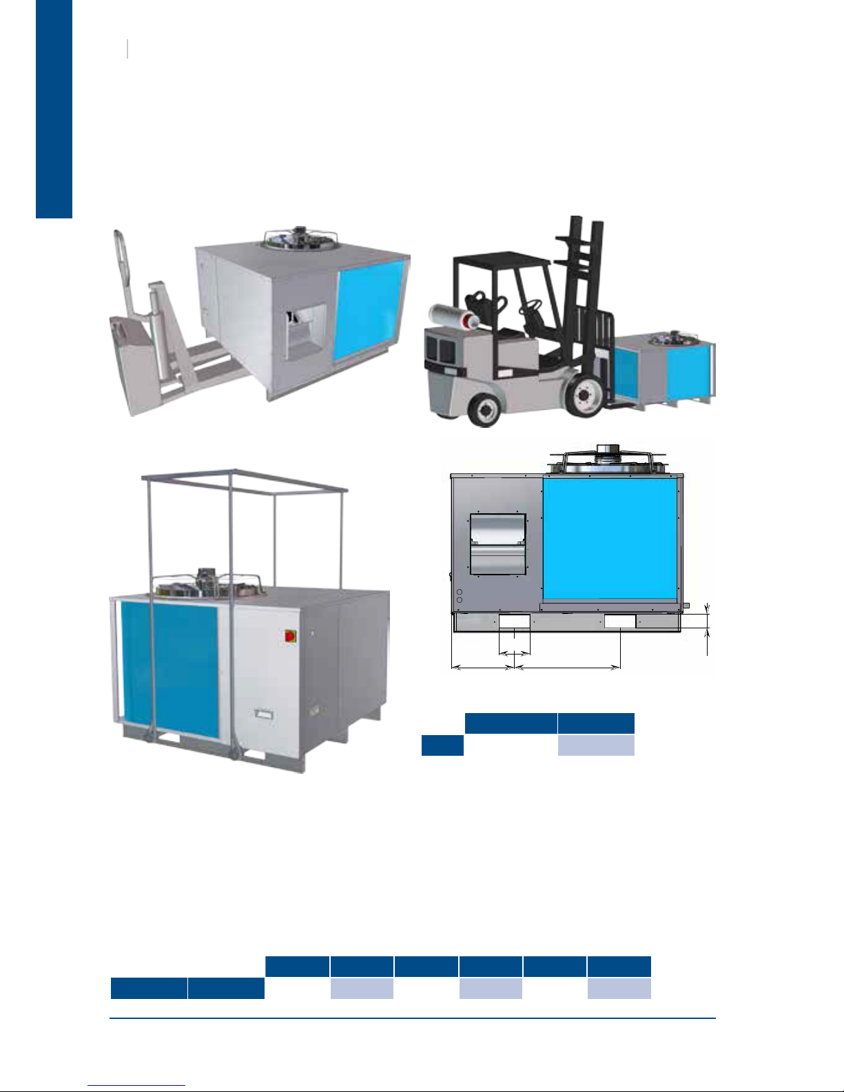
7. HANDLING
SEE APPENDIX
7.1. NET WEIGHT
The unit can also be lifted by using slings.
A spreader must be used to avoid damaging the casing of the machine.
13-15-17-19 25-31
A
360 425
13 15 17 19 25 31
Weight Kg
219 223 223 243 320 343
Page 9
English
7
HAN
8. TECHNICAL SPECIFICATIONS
IMPORTANT
A main fuse must mandatorily be provided on the power supply.
² Fuses not supplied
² Cables not supplied
Units are supplied pre-charged with refrigerant uid.
This equipment contains uorinated gas with greenhouse gas effects covered by the Kyoto agreement.
(1) At nominal air ow and at maximum fan speed without air lter
13 15 17 19 25 31
Compressor type
Scroll Scroll Scroll Scroll Scroll Scroll
Compressor quantity
1 1 1 1 1 1
Number of circuit
1 1 1 1 1 1
Refrigerant
R410A
Charge of circuit kg
SEE NAME PLATE
13 15 17 19 25 31
Indoor fan
Number of fan
1 1 1 1 1 1
Type
Centrifugal
Drive type
Direct Belt / variable pitch pulley
Motor nominal power
input
kW
0.60 0.75 0.75 1.10 1.10 1.50
Power supply V/Ph/Hz
230V/1~/50Hz 400V / 3~N /50Hz
Nominal airow m3/h
2640 2940 3190 3860 4780 5530
Available static
pressure
(1)
Pa
100 170 160 210 240 250
Outdoor fan
Number of fan
1 1 1 1 1 1
Type
Propeller
Number of blades
3 3 3 3 5 5
Fan diameter mm
610 610 610 610 710 710
Drive type
Direct
Nominal airow m3/h
9000 9000 9000 9000 12000 12000
Motor nominal power
input
kW
0.49 0.49 0.49 0.49 0.90 0.90
Power supply V/Ph/Hz
230V/1~/50Hz
13 15 17 19 25 31
Power supply
400V / 3~N /50Hz
Maximum current A
16 17 20 21 29 30
Starting current A
70 69 79 107 119 126
Fuse rating FFG aM A
16 20 20 25 32 32
8.1. REFIGERATION SPECIFICATIONS
8.2. ELECTRICAL SPECIFICATIONS
8.3. AERAULIC SPECIFICATIONS
Page 10

English
8
HAN
8.4. OPERATING LIMITS
13 15 17 19 25 31
Cooling mode
Outside temperature
min. for standard
version
°C
15 15 15 15 15 15
Outside temperature
min. with all seasons
kit
°C
-10 -10 -10 -10 -10 -10
Inside temperature
min. DB/WB
°C
21 / 15 21 / 15 21 / 15 21 / 15 21 / 15 21 / 15
Outside temperature
max..
°C
50 50 50 50 50 50
Inside temperature
max. DB/WB
°C
32 / 23 32 / 23 32 / 23 32 / 23 32 / 23 32 / 23
Heating mode
Outside temperature
min.
°C
-10 -10 -10 -10 -10 -10
Outside temperature
max. DB
°C
24 24 24 24 16 24
Inside temperature
max. DB
°C
27 27 27 27 27 27
The All Seasons kits modulates the outdoor fan speed to enable the machine to operate in Cooling mode at
outdoor ambient temperatures as low as -10°C.
DB: Dry Bulb temperature
WB: Wet bulb temperature
Page 11
English
9
HAN
The unit is not designed to withstand weights or stresses from adjacent equipment, pipe work
or constructions. Any foreign weight or stress on the unit structure could lead to a malfunction
or a collapse with dangerous consequences for personnel and property. In such an event, the
warranty shall be null and avoid.
9. INSTALLATION
² The building structure must be capable to carrying the weight of the unit during operation.
² The place of installation must not be subject to ooding.
² The HAN should be installed on a at, clean surface without any obstacles. The surface area must be
sufcient to spread the weight of the unit over the building structure.
² Ensure that the recommended free clearances around the unit are maintained to avoid any risk of
malfunctions.
² Ensure that there are no obstructions around the condenser or the air outlet to avoid any risk of
recycling old air.
² In addition to the service clearances stated on the dimensions sheet, it is imperative to provide a
safe and appropriate access to the unit for repairs and servicing.
² The installer is responsible for providing the weaterproof seal between the building and the HAN. The
installer must be fully versed in the practice of roof mounted equipments and must comply with the
recommendations and rules detailed in the Technical Directives.
² In order to avoid risk of condensation and energy losses, all outdoor ducting and piping must be
insulated.
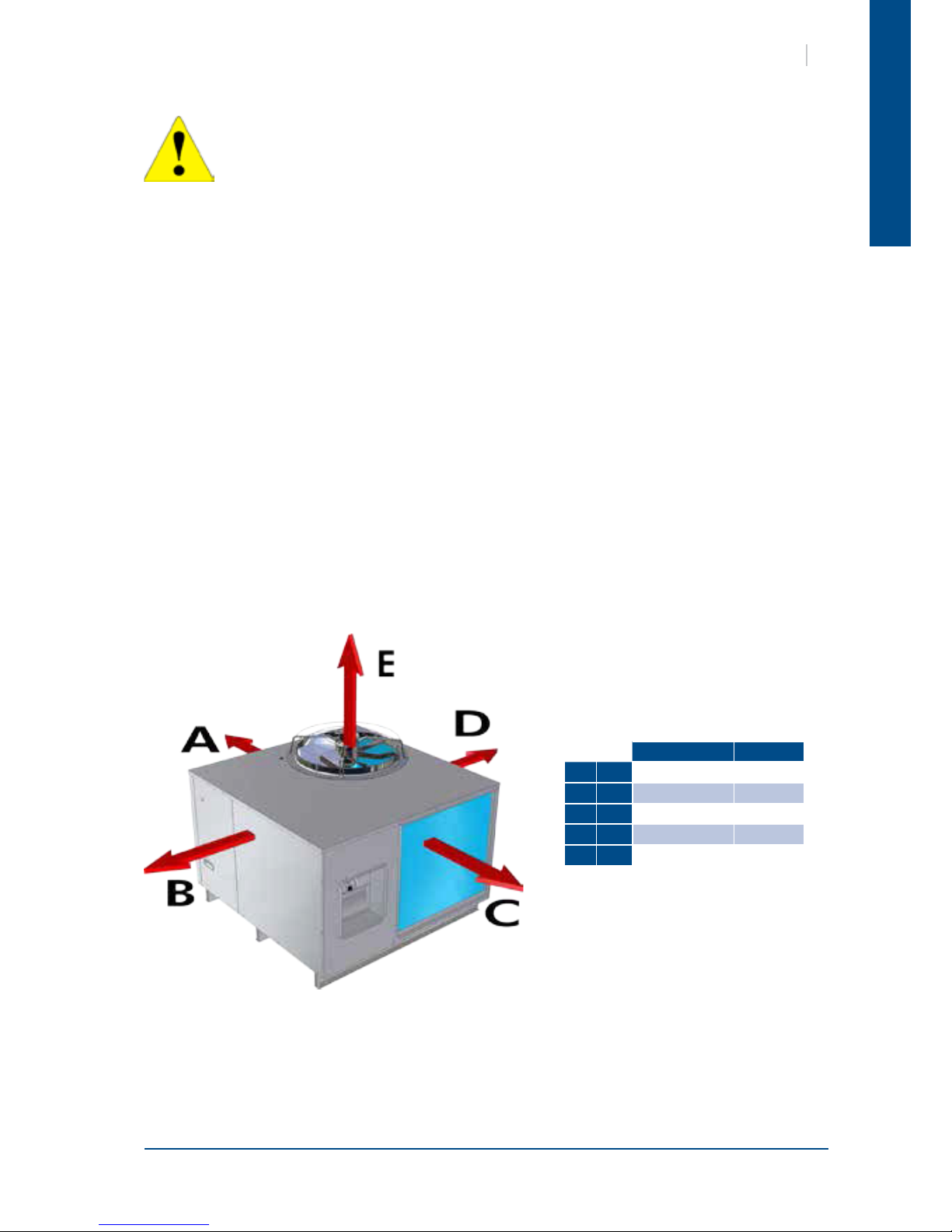
9.1. PLACE OF INSTALLATION AND REQUIREMENTS
SEE APPENDIX
13-15-17-19 25-31
A mm
800 800
B mm
800 800
C mm
800 800
D mm
850 1000
E mm
3000 3000
9.2. CLEARANCE
9.3. ATTACHMENT TO THE GROUND
Page 12

English
75 mm (Mini)
2% Mini
Ø1" (25.4 mm)
75 mm
A
30
A
B
C
D
G
H
F
D
10
HAN
Syphon to be supplied
by the installer
The installer must imperatively initiate thte syphon action.
9.5.1. AIR INTAKE AND BLOWING DUCT OUTLET DIMENSIONS
13-15-17-19 25-31
A
156 156
A B C D E F G H
13
290 295 110 272 35 765 155 712
15-17-19
320 345 110 316 35 765 155 712
25
320 345 137 316 35 860 155 1030
31
320 345 85 405 35 860 155 1030
CAUTION
For Heat pump models, where the outdoor temperature is likely to fall below +1°C, provide a system
to prevent the syphon from freezing (e.g. heating cord).
9.4. CONDENSATE DRAIN PAIN
9.5. AERAULIC CONNECTIONS
Page 13

English
10 mm maxi.
5 kg
90
11
HAN
If the unit is to be equipped with an electric heating kit, the latter must be installed on the blown air duct
inside the building.
Safety devices (automatic and manual reset thermostats) protect the appliance against any possible risks of
overheating due to insufcient ow around the shielded elements.
The electric heating kit power supply must be separated from the HAN unit's power supply. Only the electric
heating control functions are managed by the HAN unit (refer to appended wiring diagrams).
9.5.2. AIR FLOW / PRESSION ADJUSTMENT
SEE TO APPENDED AERAULIC CHARACTERISTICS
The HAN models 13 are equipped with direct drive centrifugal compressors.
From HAN model 15 upwards, air ow / static pressure is adjusted via a variable pulley. When adjusting this
pulley it is important to ensure that the drive belt is positioned correctly. The latter must not move out of its
groove or be located at the bottom of the groove. The pulley/drive belt assembly must be perfectly aligned
and the belt must be properly tightened in accordance with specications.
For a quick check, make sure that the small
rope touch each end of the pulleys as
shown on drawing above.
Belt alignment Belt tensioning
The HAN roof-mounted units are designed for ducted applications. In the event of an
application without a duct network on the blowing side ("free" blowing) it is necessary to
create an articial pressure loss on the blowing side to avoid damage to the fan motor due to
an abnormally high current draw. This pressure loss can be created for example by adding a
perforated plate that will also have the effect of improving blown air distribution.
To achieve optimal performance, this plate should be of an adequate size and suitably positioned to ensure
that the airow is close to the unit's nominal airow.
Perforated plate
(air distributor)
10. ELECTRIC HEAT
Page 14

English
12
HAN
SE 3676 HAN 13 400V/3N~/50Hz +/- 10%
SE 3678 HAN 15/17/19 400V/3N~/50Hz +/- 10%
SE 3679 HAN 25/31 400V/3N~/50Hz +/- 10%
FFG : Protective fuses (not supplied)
Q1 : Mains supply circuit switch
K1 : M1 compressor power circuit contactor
KA1 : Three-phase network control relay (phase sequence and cut-out)
HP1 : Automatic reset high-pressure pressostats
LP1 : Automatic reset low-pressure pressostats
M1 : Compressor
R1 : M1 compressor crankcase heater
RV1 : Cycle inversion valve (option)
MO1 : Outdoor fan motor
CO1 : Outdoor fan motor condenser
FO1 : MO1 motor internal protection
MI3 : Indoor fan motor
K3 : MI3 contactor.
FT3: MI3 thermal relay.
11.1. WIRING DIAGRAM
11.2. LEGEND
11.2.1. POWER SUPPLY
This supply is protected upstream by an FFG general supply fuse holder, to be provided by the installer, in
accordance with "ELECTRICAL SPECIFICATIONS".
The electrical installation and the wiring of this unit shall comply with local electrical installation standards.
² Three phase 400 V~ + Neutral + Ground:
On terminals PE, N, L1, L2, L3 on the Q1 mains supply circuit switch.
On the ground screw for the earth cable.
11.2.2. WIRING DIAGRAM KEY DESCRIPTIONS
11.2.2.1. COOLING / SAFETY
11.2.2.2. VENTILATION
N771
SEE APPENDIX
11. WIRING DIAGRAM AND LEGEND
Page 15

English
13
HAN
11.2.2.3. CONTROL AND REGULATION
RT : Ambient temperature probe (option)
ICT : Indoor exchanger temperature probe
OCT : Outdoor exchanger temperature probe
SM1 : Remote ON/OFF switch (not supplied) (remove the "SHM" shunt on the circuit board)
K5/6 : Heating elements power contactors
FM5/6 : Heating manual reset safety thermostat
FA5/6 : Heating automatic reset safety thermostat
11.2.2.4. ELECTRIC HEATING KIT
13 15 17 19 25 31
Thermal relay
FT3
Range
/ 1.8-2.6A 1.8-2.6A 1.8-2.6A 2.6-3.7A 2.6-3.7A
Adjustment
/ 1.9A 1.9A 2.5A 2.6A 3.4A
Contactor AC3
K1
12A 18A 18A 18A 25A 25A
K3
/ 9A 9A 9A 9A 9A
13 15 17 19 25 31
Power w
70 70 70 70 90 90
11.2.3. RANGE AND SETTINGS OF THEMAL PROTECTION / NOMINAL INTENSITY OF THE CONTACTORS
(CLASSE AC3)
11.2.4. COMPRESSOR CRANKCASE HEATER
11.2.5. PRESSOSTATS SETTING
LP1 : Factory low pressure adjustment 2bars (29PSI)
HP1 : Factory high pressure adjustment 42bars (609.16PSI)a
11.2.6. COLOUR CODE
BK : Black OG : Orange GNYE : Green/Yellow
BN : Brown WH : White RD : Red
BU : Blue GY : Grey VT : Violet
YE : Yellow
Page 16

English
14
HAN
12. ELECTRICAL CONNECTIONS
WARNING
BEFORE CARRYING OUT ANY WORK ON THE EQUIPMENT,
MAKE SURE THAT THE ELECTRICAL POWER SUPPLY IS
DISCONNECTED AND THAT THERE IS NO POSSIBILITY OF THE
UNIT BEING STARTED INADVERTENTLY.
NON-COMPLIANCE WITH THE ABOVE INSTRUCTIONS CAN
LEAD TO INJURY OR DEATH BY ELECTROCUTION.
The electrical installation must be performed by a fully qualied electrician, and in accordance with local
electrical standards and the wiring diagram corresponding to the unit model.
Any modication performed without our prior authorisation may result in the unit’s warranty being declared
null and void.
The power supply cable section must be sufcient to provide the appropriate amperage to the unit’s main
power terminals, at start-up and under full load operating conditions.
The power supply cable shall be selected in accordance with the following criteria:
1. Power supply cable length.
2. Maximum unit starting current draw – the cables shall supply the appropriate amperage to the unit
terminals for starting.
3. Power supply cables’ installation mode. (do not leave cable weight hang on connecting lugs)
4. Cables’ capacity to transport the total system current draw.
Short circuit protection shall be provided by others. This protection shall comprise fuses or circuit breakers
with high breaking capacity, mounted on the distribution board. The distribution board must support the
intensity of the whole of the machines installed.
VERY IMPORTANT:
3N~400V-50Hz +
The outdoor unit is equipped as standard with a phase sequence and cut-out controller located in the
electrical box.
THIS PRODUCT IS EQUIPPED WITH A PHASE SEQUENCE CONTROLLER. THE LED’s INDICATE THE FOLLOWING
CONDITIONS:
Green LED = 1
Yellow LED =1
Low voltage supply
The compressor rotation
direction is correct
Green LED = 1
Yellow LED =0
Phase inversion or phase
absent (L1)
The compressor and the fans
do not start.
Green LED = 0
Yellow LED =0
Phase absent (L2 or L3)
the compressor and the fans
do not start.
Page 17

English
RS485
GND
12v
12V
GND
1
2
RT
GND
15
HAN
Use a pozidrive M3.5 screwdriver, Form Z, to make the connections.
These units are equipped with a local switch used as general terminal board.
The proximity switch can be mounted at two different locations:
The switch can be padlocked.
A circuit breaker or fuse holder ( not supplied ) must be installed on the main
power supply of the unit in accordance with the circuit diagram; for the raitings,
refer to the electrical specications.
3N~400V
12.1. CONNECTION OF RCW2 AND REMOTE ROOM TEMPERATURE
100 m MAXI
1 mm² MAXI
Shielded cable
IF the RT sensor is not used, the RCW2 must be congured in Zone 1 with the local temperature function
activated.
Remote room
temperature sensor
delivred with the
machine (optional
installation)
1000 m MAXI
Shielded 2 twisted pairs cable
with setting with terminal GND.
0,12 à 0,3 mm²
Page 18

English
16
HAN
13. COMMISSIONING
13.1. PRE-START CHECK LIST
13.1.1. ELECTRICAL CHECK
1. Electrical installation has been carried out according to unit wiring diagram and the Supply Authority
Regulations.
2. size fuses or circuit breaker has been installed at the main switchboard.
3. Supply voltages as specied on unit wiring diagram.
4. All cables are properly identied and tight connected at the unit.
5. That the wiring is not in contact with surfaces subject to high temperatures or sharp angles, or is
protected against such risks.
13.1.2. VISUAL CHECK
1. Clearances around unit including outdoor air entry and discharge openings and service accesses.
2. Unit mounted as specied.
3. For loose or missing bolts or screws.
4. For refrigerant leaks in connections and components.
5. All panels are in place and secured.
6. The unit is clean and free of any extraneous installation materials.
13.1.3. DUCTING
1. Connections exible type, secure and detachable for service access.
2. Fan drive from HAN model 15 upwards
Correct variable diameter pulley adjustment guaranteeing the intended air quantity and static
pressure (see § "AIR FLOW / PRESSURE ADJUSTMENT").
3. Check that the fan shaft and motor pulleys are mounted correctly and turn true.
4. Ensure that both pulley grooves are correctly aligned. Improper alignment of the pulleys and belt
may cause vibration in the blower drive and result in premature wear and noise.
Page 19

English
17
HAN
13.2.4. AIR BALANCING
A variable pulley is tted to the motor shaft in order to adjust the blower performance to the pressure drop
at the duct work. The pulley must be adjusted when the measured external static pressure and air volume
(motor current draw) differ from the nominal values at the unit. As a default setting, the variable diameter
pulley is open by 2 turns.
13.2.4.1. CASE N°1:
The measured air ow is higher than the nominal air ow. You must reduce the fan rotation speed by
opening the variable diameter pulley. It is imperative to adjust the pulley, otherwise the motor’s internal
protection will trigger because of overheating taking the entire unit out of operation.
13.2.4.2. CASE N°2:
The measured air ow is lower than the nominal air ow. You must increase the fan rotation speed by
closing the variable diameter pulley.
13.2. OPERATING CHECK LIST
13.2.1. GENERAL
Cheek for any unusual noises or vibration in the running components, particularly at the main blower.
13.2.2. PHASE ROTATION PROTECTION
If the phase at the power supply are not correct, the phase rotation protection device will prevent the
machine from starting.
13.2.3. ELECTRICAL
13.2.3.1. OPERATING VOLTAGE:
Recheck voltage at unit supply terminals.
13.2.3.2. CONTROL
1. Operate system and thermostat switches.
2. Check unit is wired for correct control of blower, cooling and heating modes.
3. Verify all sensor signal, using the controller display.
This section applies to all HAN from model 15.
13.2.5. COMPRESSOR AND REFRIGERATION SYSTEM
1. If outdoor air temperature is below 0°C make sure that the compressor crankcase heater has been on
for at least one hour before starting compressor.
2. Running check: Start the compressor. Check for any unusual noise or vibration.
3. Operating Pressures: Operate the unit for at last 20 minutes and ensure that the refrigerant pressures
are stabilised, and cheek that they are within the normal operating ranges.
4. Operating Temperature: Check discharge, suction and liquid temperatures.
5. Compressor output temperature in cooling mode should not normally exceed 105° C.
6. Compressor intake air superheating must be between 5° K and 12° K.
Page 20

English
18
HAN
The user is responsible for ensuring that it is in a proper working condition and that technical
installation as well as the regular maintenance operations are performed by properly trained
technicians and in accordance with the instructions contained in this manual.
17. MAINTENANCE
17.1. REGULAR MAINTENANCE
These units have been designed to require only minimal servicing, thanks to the use of a maximum number
of lubricated-for-life components. Nevertheless, certain regular servicing operations are necessary to
guarantee optimal system operation.
Servicing must be performed by experienced and qualied personnel only.
WARNING : Isolate unit from main power supply before working on unit.
14. FINAL TASKS
Operate the air conditioner in the presence of the user and explain all functions.
As required, demonstrate lter removal, cleaning and replacement.
15. IN CASE OF WARRANTY - MATERIAL RETURN PROCEDURE
Material must not be returned without permission of our After Sales Department.
To return the material, contact your nearest sales ofce and ask for a "return form". The return form shall
be sent with the returned material and shall contain all necessary information concerning the problem
encountered.
The return of the part is not an order for replacement. Therefore, a purchase order must be entered through
your nearest distributor or regional sales ofce. The order should include part name, part number, model
number and serial number of the unit involved.
Following our personal inspection of the returned part, and if it is determined that the failure is due to faulty
material or workmanship, and in warranty, credit will be issued on customer's purchase order. All parts shall
be returned to our factory, transportation charges prepaid.
16. ORDERING SERVICE AND SPARE PARTS ORDER
The part number, the order conrmation and the unit serial number indicated on the name plate must be
provided whenever service works or spare parts are ordered.
For any spare part order, indicate the date of unit installation and date of failure. Use the part number
provided by our service spare parts, if it not available, provide full description of the part required.
IT IS RECOMMENDED THAT THE DISCONNECT SWITCH BE PADLOCKED
CAUTION
BEFORE CARRYING OUT ANY OPERATION ON THE EQUIPMENT, CHECK THAT THE
ELECTRICAL POWER SUPPLY IS SWITCHED OFF AND THAT IT CANNOT BE SWITCHED
ON INADVERTENTLY.
Page 21

English
19
HAN
17.2. GENERAL INSPECTION
Carry out a visual inspection of the complete installation in service.
Check the general cleanness of the installation, and check if the condensate evacuations is not blocked,
specialy on the indoor coil, before the cooling season.
Check the condition of the condesate tray by pulling it out of the casing.
17.3. OPENING OF ACCESS PANELS
All access panels are removable by unscrewing the self tapping retaining screws.
17.4. BLOWER DRIVE SYSTEM
blower shaft and motor bearings are of permanently lubricated, sealed type and require no regular
maintenance other than a check on their general condition. The blower belt tension should be checked
regularly and belt surfaces inspected for cracks or excessive wear.
17.5. COILS
The refrigeration system is hermetically sealed and should require no regular maintenance. However, it is
recommended to leak test the refrigerant system and check the general operating conditions and control
devices on a regular basis. The operating pressures should be checked particularly as they are an excellent
guide for maintenance. This equipment must be subjected to regular tightness checks conducted by qualied
personnel. Please refer to national requirements to determine the frequency of these checks. After any
intervention requiring the opening of the refrigerant circuit, the system must be completely vacuum drained
by using the pressure tap installed for this purpose (Refer to the appended refrigerant circuit diagram).
Clean the heat exchanger using a special product for aluminium-copper heat exchangers, and rinse with
water. Do not use hot water or steam, as this could cause the pressure of the refrigerant to rise.
Check that the surface of the aluminium ns of the heat exchanger is not damaged by impacts or scratches,
and clean with an appropriate tool if necessary.
If necessary, the air lter located on the air intake must be cleaned
or replaced at regular intervals to ensure that unit operate properly.
A clogged lter causes a reduction in the airow across the heat
exchanger and this reduces the performance output.
The filters are located
on slide rails upstream
of the evaporator.
A system of sliding rails
enables you to remove
the lters without
having to remove the aeraulic duct.
17.6. ELECTRICAL SECTION
The contact surfaces of relays and contactors should be inspected regularly by an electrician and replaced
as judged necessary.
On these occasions the control box should be blown out with compressed air to remove any gathwing of
dust.
Check that the main power supply cable is not damaged or altered in such a way as to affect the insulation.
Check the earth grounding connection.
Page 22

English
20
HAN
18. TROUBLE SHOOTING
Problem Probable cause Solution
Unit operates
continuously but
without performing
Insufficient refrigerant charge. Top up the refrigerant fluid charge.
Reduced output
Check the 4 way valve on the compressor and replace the
valve if necessary.
Frozen suction line
The overheating setting on the thermostatic
expansion valve is too low.
Increase the setting.
Insufficient refrigerant charge Add refrigerant charge.
Evaporator freezing
Filters clogged Replace filters
Insufficient charge Add refrigerant charge.
Excessive noise
Vibrating pipe work
Attach the pipe work correctly.
Check the pipe work attachments.
Whistling noise from the thermostatic expansion
valve
Add refrigerant charge.
Noisy compressor Check the pressure difference of the 4-ways valves.
No pressure increase / mechanical damage to the
compressor
Contact an approved Service Centre.
Low oil level in the
compressor
Presence of one or several oil or gas leaks in the
circuit
Locate and repair the leaks and add oil
Mechanical compressor damage. Contact an approved Service Centre.
Crankcase oil heater resistance fault.
Check the electrical circuit and the condition of the
resistance. Replace defective parts if necessary.
compressor do not
operate.
No power at compressor
Check the electrical circuit and seek out any grounding
and/or short- -circuits. Check the fuses.
High pressure pressostat activated. Check for dirty condenser coil or defective fan
Control circuit fuse blown.
Check the control circuit and look for any grounding and/or
short-circuits. Replace the fuses.
Connection problem
Check the tightness of all the electrical connection
terminals.
Electrical circuits thermal protection cuts in. Check the operation of the control and safety devices.
Incorrect wiring. Check the wiring of the control and safety devices.
Mains voltage too low.
Check the power line.If the problem is due to the network,
inform the Electricity Company.
Compressor motor short–circuited. Check the continuity of the motor winding.
Compressor seized Replace the compressor.
Low pressure
pressostat being
activated.
Presence of a leak. Identify and repair the leak.
Insufficient refrigerant fluid charge. Add refrigerant charge.
Low air volume on evaporator check the blower and duct
High pressure
pressostat being
activated.
Incorrect operation of the high pressure
pressostat.
Check the operation of the pressostat. Replace it if
required.
Outlet valve partially closed. Open the valve. Replace it if required.
Non-condensable particles in the circuit. Bleed the circuit
Condenser fan not operating.
Check the wiring and the motors. Repair and replace if
required.
Liquid line too hot
Insufficient refrigerant charge.
Locate and eliminate the causes of charge losses and top
up the refrigerant fluid charge.
Fans do not operate.
Electrical circuit problems. Check the connections.
Internal circuit thermal cut-out activated. Contact an approved Service Centre.
Fan surging
Duct network pressure too low.
Generate an additional pressure loss (refer to aeraulic
curves)
Reduced output in
both Heating and
Cooling mode
Compressor operating fault Contact an approved Service Centre.
Outdoor coil dirty Clean the coil.
Insufficient refrigerant charge. Add refrigerant charge.
Lack of air flow
Clean the battery
Replace the filter
Check the air flow / pressure settings
Page 23

APPENDIX
ANNEXE
ANLAGE
ALLEGATO
ANEXO
APPENDIX / ANNEXE / ANLAGE / ALLEGATO / ANEXO
Page 24

ANEXO
ALLEGATO
ANLAGE
ANNEXE
APPENDIX
DIMENSIONS ................................................................................III
HAN 13 / 15 / 17 / 19 .................................................................................... III
HAN 25 / 31 ...................................................................................................... IV
SCHEMA DU CIRCUIT FRIGORIFIQUE ..............................................V
SCHEMAS ELECTRIQUES .............................................................. VI
HAN 13 ..............................................................................................................VII
HAN 15 / 17 / 19 ...........................................................................................VIII
HAN 25 / 31 ...................................................................................................... IX
CARACTERITIQUES AERAULIQUES .................................................X
ABMESSUNGEN ............................................................................III
HAN 13 / 15 / 17 / 19 .................................................................................... III
HAN 25 / 31 ...................................................................................................... IV
KÄLTEKREISLAUFDIAGRAMM .......................................................V
STROMLAUFPLANS ..................................................................... VI
HAN 13 ..............................................................................................................VII
HAN 15 / 17 / 19 ...........................................................................................VIII
HAN 25 / 31 ...................................................................................................... IX
REGELUNG DES LÜFTERSYSTEMS ..................................................X
DIMENSIONI .................................................................................III
HAN 13 / 15 / 17 / 19 .................................................................................... III
HAN 25 / 31 ...................................................................................................... IV
SCHEMA DEL CIRCUITO REFRIGERANTE .........................................V
SCHEMA ELETRICO ...................................................................... VI
HAN 13 ..............................................................................................................VII
HAN 15 / 17 / 19 ...........................................................................................VIII
HAN 25 / 31 ...................................................................................................... IX
REGOLAZIONE DEL SISTEMA
DI TRATTAMENTO DELL'ARIA ........................................................X
DIMENSIONES ..............................................................................III
HAN 13 / 15 / 17 / 19 .................................................................................... III
HAN 25 / 31 ...................................................................................................... IV
ESQUEMA DEL CIRCUITO FRIGORIFÍCO...........................................V
ESQUEMA ELECTRICO .................................................................. VI
HAN 13 ..............................................................................................................VII
HAN 15 / 17 / 19 ...........................................................................................VIII
HAN 25 / 31 ...................................................................................................... IX
AJUSTE DEL ISTEMA AEROLICO ......................................................X
DIMENSIONS ................................................................................III
HAN 13 / 15 / 17 / 19 .................................................................................... III
HAN 25 / 31 ...................................................................................................... IV
REFRIGERANT CIRCUIT DIAGRAM .................................................V
WIRING DIAGRAM ...................................................................... VI
HAN 13 ..............................................................................................................VII
HAN 15 / 17 / 19 ...........................................................................................VIII
HAN 25 / 31 ...................................................................................................... IX
AERAULIC ADJUSTMENT ................................................................X
II
HAN
APPENDIX / ANNEXE / ANLAGE / ALLEGATO / ANEXO
Page 25

HAN 13 / 15 / 17 / 19
1340
571
88
577
1063 1320
1147
88
152
30
6 x Ø12
DIMENSIONS
DIMENSIONS
ABMESSUNGEN
DIMENSIONI
DIMENSIONES
III
HAN
APPENDIX / ANNEXE / ANLAGE / ALLEGATO / ANEXO
Page 26

HAN 25 / 31
1420
600
102
594
1320
1267
1445
88
157
28
6 x Ø12
IV
HAN
APPENDIX / ANNEXE / ANLAGE / ALLEGATO / ANEXO
Page 27

REFRIGERANT CIRCUIT DIAGRAM
SCHEMA DU CIRCUIT FRIGORIFIQUE
KÄLTEKREISLAUFDIAGRAMM
SCHEMA DEL CIRCUITO REFRIGERANTE
ESQUEMA DEL CIRCUITO FRIGORIFÍCO
C : Compressor
CD : Condenser
EV : Evaporator
FC : Centrifugal fan
FH : Propellor fan
HP : Condensing pressure switch
BP : Evaporator pressure switch
P : Pressure Tap
TEV : Thermodynamic Expansion Valve
V : 4 way valve
C : Compresseur
CD : Condenseur
EV : Evaporateur
FC : Ventilateur centrifuge
FH : Ventilateur hélicoïde
HP : Pressostat HP
BP : Pressostat BP
P : Prise de pression
TEV : Détendeur thermostatique
V : Vanne d'inversion
C : Kompressor
CD : Verüssiger
EV : Verdampfer
FC : Zentrifugalventilator
FH : Axialventilator
HP : Druckschalter Hochdruck
BP : Druckschalter Niederdruck
P : Druckanschlussstelle
TEV : Thermostatisches Druckminderventil
V : Umkehrventil
C : Compressore
CD : Condensator
EV : Evaporatore
FC : Centrifugo ventilatore
FH : Elicoidale ventilatore
HP : Pressostato HP
BP : Pressostato BP
P : Presa di pressione
TEV : Regolatore di pressione termostatico
V : Valvola di inversione
C : Compresor
CD : Condensador
EV : Evaporador
FC : Centrifugo ventilator
FH : Helicoidal ventilator
HP : Presostato AP
BP : Presostato BP
P : Toma de presión
TEV : Reductor de presión termostático
V : Válvula de inversión
V
TEV
FH FC EVCD
P
C
P
HP
BP
P
V
HAN
APPENDIX / ANNEXE / ANLAGE / ALLEGATO / ANEXO
Page 28

WIRING DIAGRAM
SCHEMAS ELECTRIQUES
STROMLAUFPLANS
SCHEMA ELETRICO
ESQUEMA ELECTRICO
TAKE CARE!
These wiring diagrams are correct at the time of publication. Manufacturing changes can lead to
modications. Always refer to the diagram supplied with the product.
ATTENTION
Ces schémas sont corrects au moment de la publication. Les variantes en fabrication peuvent entraîner
des modications. Reportez-vous toujours au schéma livré avec le produit.
ACHTUNG!
Diese Stromlaufplans sind zum Zeitpunkt der Veröffentlichung gültig. In Herstellung bendliche Varianten
können Änderungen mit sich bringen. In jedem Fall den mit dem Produkt gelieferten Stromlaufplan
hinzuziehen.
ATTENZIONE !
Questi schemi sono corretti al momento della pubblicazione. Le varianti apportate nel corso della
fabbricazione possono comportare modiche. Far sempre riferimento allo schema fornito con il prodotto.
ATENCIÓN !
Esto esquemas son correctos en el momento de la publicación. Pero las variantes en la fabricación pueden
ser motivo de modicaciones. Remítase siempre al esquema entregado con el producto.
PUESTA FUERA DE TNESIÓN OBLIGATORIA ANTES DE CUALQUIER
INTERVENCIÓN EN LAS CAJAS ELÉCTRICAS!
PRIMA DI OGNI INTERVENTO SULLE CASSETTE ELETTRICHE ESCLUDERE
TASSATIVAMENTE L’ALIMENTAZIONE !
VOR JEDEM EINGRIFF AN DEN ANSCHLUßKÄSTEN UNBEDINGT DAS GERÄT
ABSCHALTEN!
MISE HORS TENSION OBLIGATOIRE AVANT TOUTE INTERVENTION DANS LES
BOITIERS ELECTRIQUES.
POWER SUPPLY MUST BE SWITCHED OFF BEFORE STARTING TO WORK IN
THE ELECTRIC CONTROL BOXES!
VI
HAN
APPENDIX / ANNEXE / ANLAGE / ALLEGATO / ANEXO
Page 29

HAN 13
T1PRI
T1SEC
>
>
<
>
VII
HAN
APPENDIX / ANNEXE / ANLAGE / ALLEGATO / ANEXO
Page 30

HAN 15 / 17 / 19
T1PRI
T1SEC
>
>
> >
<
>
VIII
HAN
APPENDIX / ANNEXE / ANLAGE / ALLEGATO / ANEXO
Page 31

HAN 25 / 31
T1PRI
T1SEC
>
>
>>
<
>
IX
HAN
APPENDIX / ANNEXE / ANLAGE / ALLEGATO / ANEXO
Page 32

AERAULIC ADJUSTMENT
CARACTERITIQUES AERAULIQUES
REGELUNG DES LÜFTERSYSTEMS
REGOLAZIONE DEL SISTEMA DI TRATTAMENTO DELL'ARIA
AJUSTE DEL ISTEMA AEROLICO
HAN 13
WITHOUT AIR FILTER
SANS FILTRE À AIR
OHNE LUFTFILTER
SENZA FILTRO AD ARIA
SIN FILTRO A AIRE
WITH AIR FILTER
AVEC FILTRE À AIR
MIT LUFTFILTER
CON FILTRO AD ARIA
CON FILTRO A AIRE
0
20
40
60
80
100
120
140
160
180
2100 2200 2300 2400 2500 2600 2700 2800 2900
Pa
GV
PV
m3/h
2640
0
20
40
60
80
100
120
140
160
180
200
2100 2200 2300 2400 2500 2600 2700 2800 2900
Pa
GV
PV
m3/h
2640
X
HAN
APPENDIX / ANNEXE / ANLAGE / ALLEGATO / ANEXO
Page 33

HAN 15
WITHOUT AIR FILTER
SANS FILTRE À AIR
OHNE LUFTFILTER
SENZA FILTRO AD ARIA
SIN FILTRO A AIRE
WITH AIR FILTER
AVEC FILTRE À AIR
MIT LUFTFILTER
CON FILTRO AD ARIA
CON FILTRO A AIRE
0
20
40
60
80
100
120
140
2350 2450 2550 2650 2750 2850 2950 3050 3150
Pa
m
3
/h
2940
Closed pulley
Open pulley of 3 turns
0
20
40
60
80
100
120
140
160
180
200
2350 2450 2550 2650 2750 2850 2950 3050 3150
Pa
m
3
/h
2940
Closed pulley
Open pulley of 3 turns
XI
HAN
APPENDIX / ANNEXE / ANLAGE / ALLEGATO / ANEXO
Page 34

HAN 17
WITHOUT AIR FILTER
SANS FILTRE À AIR
OHNE LUFTFILTER
SENZA FILTRO AD ARIA
SIN FILTRO A AIRE
WITH AIR FILTER
AVEC FILTRE À AIR
MIT LUFTFILTER
CON FILTRO AD ARIA
CON FILTRO A AIRE
0
20
40
60
80
100
120
140
2550 2650 2750 2850 2950 3050 3150 3250 3350 3450
Pa
m
3
/h
3190
Closed pulley
Open pulley of 3 turns
0
20
40
60
80
100
120
140
160
180
200
2550 2650 2750 2850 2950 3050 3150 3250 3350 3450
Pa
m
3
/h
3190
Closed pulley
Open pulley of 3 turns
XII
HAN
APPENDIX / ANNEXE / ANLAGE / ALLEGATO / ANEXO
Page 35

HAN 19
WITHOUT AIR FILTER
SANS FILTRE À AIR
OHNE LUFTFILTER
SENZA FILTRO AD ARIA
SIN FILTRO A AIRE
WITH AIR FILTER
AVEC FILTRE À AIR
MIT LUFTFILTER
CON FILTRO AD ARIA
CON FILTRO A AIRE
0
50
100
150
200
250
3100 3200 3300 3400 3500 3600 3700 3800 3900 4000 4100 4200
Pa
m
3
/h
3860
Closed pulley
Open pulley of 3 turns
0
50
100
150
200
250
3100 3200 3300 3400 3500 3600 3700 3800 3900 4000 4100 4200
Pa
m
3
/h
3860
Closed pulley
Open pulley of 3 turns
XIII
HAN
APPENDIX / ANNEXE / ANLAGE / ALLEGATO / ANEXO
Page 36

HAN 25
WITHOUT AIR FILTER
SANS FILTRE À AIR
OHNE LUFTFILTER
SENZA FILTRO AD ARIA
SIN FILTRO A AIRE
WITH AIR FILTER
AVEC FILTRE À AIR
MIT LUFTFILTER
CON FILTRO AD ARIA
CON FILTRO A AIRE
0
50
100
150
200
250
300
385039504050415042504350445045504650475048504950 505051505250
Pa
m
3
/h
4780
Closed pulley
Open pulley of 3 turns
0
50
100
150
200
250
300
385039504050415042504350445045504650475048504950 505051505250
Pa
m
3
/h
4780
Closed pulley
Open pulley of 3 turns
XIV
HAN
APPENDIX / ANNEXE / ANLAGE / ALLEGATO / ANEXO
Page 37

HAN 31
WITHOUT AIR FILTER
SANS FILTRE À AIR
OHNE LUFTFILTER
SENZA FILTRO AD ARIA
SIN FILTRO A AIRE
WITH AIR FILTER
AVEC FILTRE À AIR
MIT LUFTFILTER
CON FILTRO AD ARIA
CON FILTRO A AIRE
0
50
100
150
200
250
300
4450 4600 4750 4900 5050 5200 5350 5500 5650 5800 5950 6100
Pa
m
3
/h
5530
Closed pulley
Open pulley of 3 turns
0
50
100
150
200
250
300
4450 4600 4750 4900 5050 5200 5350 5500 5650 5800 5950 6100
Pa
m
3
/h
5530
Closed pulley
Open pulley of 3 turns
XV
HAN
APPENDIX / ANNEXE / ANLAGE / ALLEGATO / ANEXO
Page 38

XVI
HAN
APPENDIX / ANNEXE / ANLAGE / ALLEGATO / ANEXO
Page 39

And that the following paragraphs of the harmonised standards have been applied.
Et que les paragraphes suivants les normes harmonisées ont été appliqués.
Und dass die folgenden Paragraphen der vereinheitlichten Normen Angewandt wurden.
E che sono stati applicati i seguenti paragraphi delle norme armonnizzate.
Y que se han aplicado los siguientes apartados de las normas armonizadas.
HAN 13 - 15 - 17 - 19 - 25 -31
MACHINERY DIRECTIVE 98 / 37 / EEC
LOW VOLTAGE DIRECTIVE (DBT) 2006 / 95 / EEC
ELECTROMAGNETIC COMPATIBILITY DIRECTIVE 2004 / 108 / EEC
PRESSURISE EQUIPMENT DIRECTIVE (DESP) 97 / 23 / EEC
SUB-MODULE A CATEGORY I: HAN 13 - 15 - 17 - 19
SUB-MODULE A1 CATEGORY II: HAN 25 - 31
NOTIFIED BODY: TÜV RHEINLAND – 20 TER RUE DE BEZONS CS 60030 – 92415 COURBEVOIE CEDEX - FRANCE
THE PRODUCTS ARE PROVIDED WITH CE 0035 MARKING OF CONFORMITY
DIRECTIVE MACHINES 98 / 37 / C.E.E.
DIRECTIVE BASSE TENSION (DBT) 2006 / 95 / C.E.E.
DIRECTIVE COMPATIBILITE ELECTROMAGNETIQUE 2004 / 108 / C.E.E
DIRECTIVE DES EQUIPEMENTS SOUS PRESSION (DESP) 97 / 23 C.E.E.
SOUS-MODULE A CATEGORIE I : HAN 13 - 15 - 17 - 19
SOUS-MODULE A1 CATEGORIE II : HAN 25 - 31
AVEC SURVEILLANCE PAR LE TUV RHEINLAND 20 TER RUE DE BEZONS CS 60030 – 92415 COURBEVOIE CEDEX - FRANCE
LES PRODUITS SONT FOURNIS AVEC LE MARQUAGE DE CONFORMITE CE 0035
RICHTLINIE MASCHINEN 98 / 37 / EG
RICHTLINIE NIERDERSPANNUNG (DBT) 2006 / 95 / EG
RICHTLINIE ELEKTROMAGNETISHE VERTRÄGLICHKEIT 2004 / 108 / EG
RICHTLINIE FÜR AUSRÜSTUNGEN UNTER DRUCK (DESP) 97 / 23 / EG
UNTER MODUL A, KATEGORIE I : HAN 13 - 15 - 17 - 19
UNTER MODUL A1, KATEGORIE II : HAN 25 - 31
MIT KONTROLLE DURCH DEN TUV RHEINLAND 20 TER RUE DE BEZONS CS 60030 – 92415 COURBEVOIE CEDEX - FRANCE
DIE PRODUKTE WERDEN MIT DER MARKIERUNG CONFORMITE CE 0035 GELIEFERT.
DIRETTIVA MACHINE 98 / 37 / CEE
DIRETTIVA BASSA TENSIONE (DBT) 2006 / 95 / CEE
DIRETTIVA COMPATIBILITA ELETTROMAGNATICA 2004 / 108 / CEE
DIRETTIVA DEGLI IMPIANTI SOTTO PRESSIONE (DESP) 97 / 23 / CEE
SOTTOMODULO A, CATEGORIA I : HAN 13 - 15 - 17 - 19
SOTTOMODULO A1, CATEGORIA II : HAN 25 - 31
CON SUPERVISION POR EL TUV RHEINLAND 20 TER RUE DE BEZONS CS 60030 – 92415 COURBEVOIE CEDEX - FRANCE
I PRODOTTI SONO FORNITI CON LA MARCATURA DI CONFORMITE CE 0035.
DIRECTIVA MAQUIAS 98 / 37 / CEE
DIRECTIVA BAJA TENSION (DBT) 2006 / 95 / CEE
DIRECTIVA COMPATIBILIDAD ELECTROMAGNETICA 2004 / 108 / CEE
DIRECTIVA DE LOS EQUIPOS A PRESION (DESP) 97 / 23 / CEE
BAJA MODULO A, CATEGORIA I : HAN 13 - 15 - 17 - 19
BAJA MODULO A1, CATEGORIA II : HAN 25 - 31
CON SORVEGLIANZA DAL TUV RHEINLAND 20 TER RUE DE BEZONS CS 60030 – 92415 COURBEVOIE CEDEX - FRANCE
LOS PRODUCTOS SE PROPORCIONAN CON EL MARCADO DE CONFOR CE 0035.
Déclaration CE de conformité
Nous déclarons sous notre responsabilité que les produits désignés dans la présente notice sont conformes aux dispositions des directives CEE énoncées ci- après
et aux législations nationales les transposant.
EC Compliance declaration
Under our own responsibility, we declare that the product designated in this manual comply with the provisions of the EEC directives listed hereafter and with
the national legislation into which these directives have been transposed.
EG-Konformitätserklärung
Wir erklarën in eigener Verantwortung, das die in der vorliegenden Beschreibung angegebenen Produkte den Bestimungen der nachstehend erwähnten EG-
Richtlinien und den nationalen Gesetzesvorschriffen entsprechen, in denen diese Richtinien umgesetz sind.
Dichiarazione CE di conformità
Dichiariamo, assurmendone la responsasabilità, che i prodotti descritti nel presente manuale sono conformi alle disposizioni delle direttive CEE di cui sott e alle
lagislazionni nazionali che li recepiscono
Declaramos, bajo nuestra responsabilidad, que los productos designados en este manual son conformes a las disposiciones de las directivas CEE enunuciadas a
continuacion, asi como a las legislaciones nacionales que las contemplan.
Declaración CE de conformidad
EN 60 204 EN 378 EN 61 000-6-1
EN 61 000-6-3 EN 60 335-1 EN 60 335-2-40
A Tillières sur Avre
27570 - FRANCE
Le: 02/02/2015
Angélique Revel
Quality
Systemair AC SAS
Page 40

As part of our ongoing product improvement programme, our products are
subject to change without prior notice. Non contractual photos.
Dans un souci d’amélioration constante, nos produits peuvent être modiés
sans préavis. Photos non contractuelles.
In dem Bemühen um ständige Verbesserung können unsere Erzeugnisse
ohne vorherige Ankündigung geändert werden. Fotos nicht vertraglich
bindend.
A causa della politica di continua miglioria posta in atto dal costruttore, questi
prodotti sono soggetti a modiche senza alcun obbligo di preavviso. Le foto
pubblicate non danno luogo ad alcun vincolo contrattuale.
Con objeto de mejorar constantemente, nuestros productos pueden ser
modicados sin previo aviso. Fotos no contractuales.
Systemair AC SAS
Route de Verneuil
27570 Tillières-sur-Avre
FRANCE
& : +33 (0)2 32 60 61 00
6 : +33 (0)2 32 32 55 13
 Loading...