

Page 1
GB
Part number of this manual 90925520
Order number output
Document in original language | Version
Geniox Core
Air handling unit as Knock Down Ready version
Instruction about separation and reassembly
Unit sizes 16, 18, and 20 with rotary heat exchanger
Page 2
Instructions for unloading at the site as well as installation and connection |
I.1.10 Separate the air handling unit with rotary heat exchanger into doors, panels, profiles
and components to get the parts easily into the building for reassembly of the air
handling unit — sizes 16, 18 and 20
The unit is built without the use of rivets and without mastic between casing parts for easy and quick removal of panels
from profiles and internal walls.
Remove doors, panels and profiles to offer good access for the demounting and removal of components.
Internal parts to be removed are walls with fans, walls with filters, cables, control components, cabinet with controller
and rotary heat exchanger.
Reassemble the parts of the casing and reinstall the components in the opposite sequence of the separation.
Note:
During reassembly of the unit, application of the delivered mastic and placing of the delivered self-adhesive
flexible lists according to the below guidelines is important in order to achieve the air-tightness that
corresponds to Eurovent certified values.
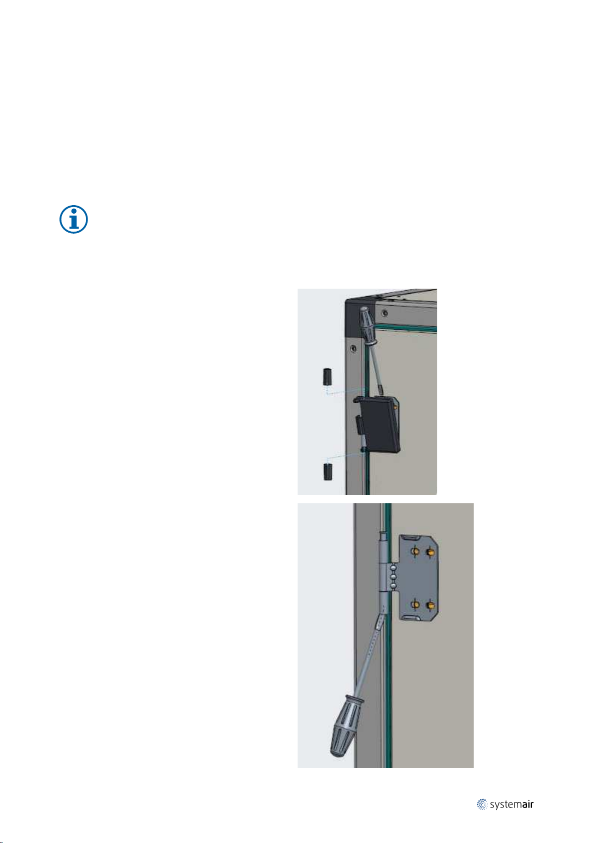
I.1.10.1 Removal of doors
Remove the 3 caps for free access to removal of the steel
shaft.
29
Remove the steel shaft in each hinge.
output |
Page 3
| Instructions for unloading at the site as well as installation and connection
30
Removal of door.
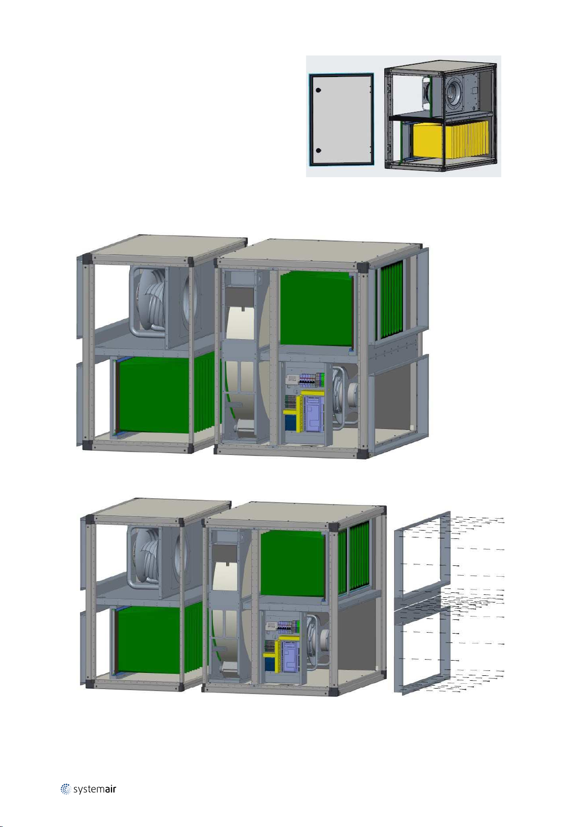
I.1.10.2 Remove panels, profiles and components
The first step is the removal of front panels.
The next step is the removal of duct connections.
output |
Page 4

Instructions for unloading at the site as well as installation and connection |
Remove the screws that hold internal walls with fans, walls with filters, as well as the rotary heat exchanger and the
cabinet.
31
Remove the walls with fans, walls with filters, as well as the rotary heat exchanger and the cabinet, cables, and control
components (cables are mounted in consoles with strips — please only cut the strips and leave the consoles without
damage. During reassembly, new strips can be inserted in the consoles for strips. New strips are included in the
delivery).
output |
Page 5
| Instructions for unloading at the site as well as installation and connection
32
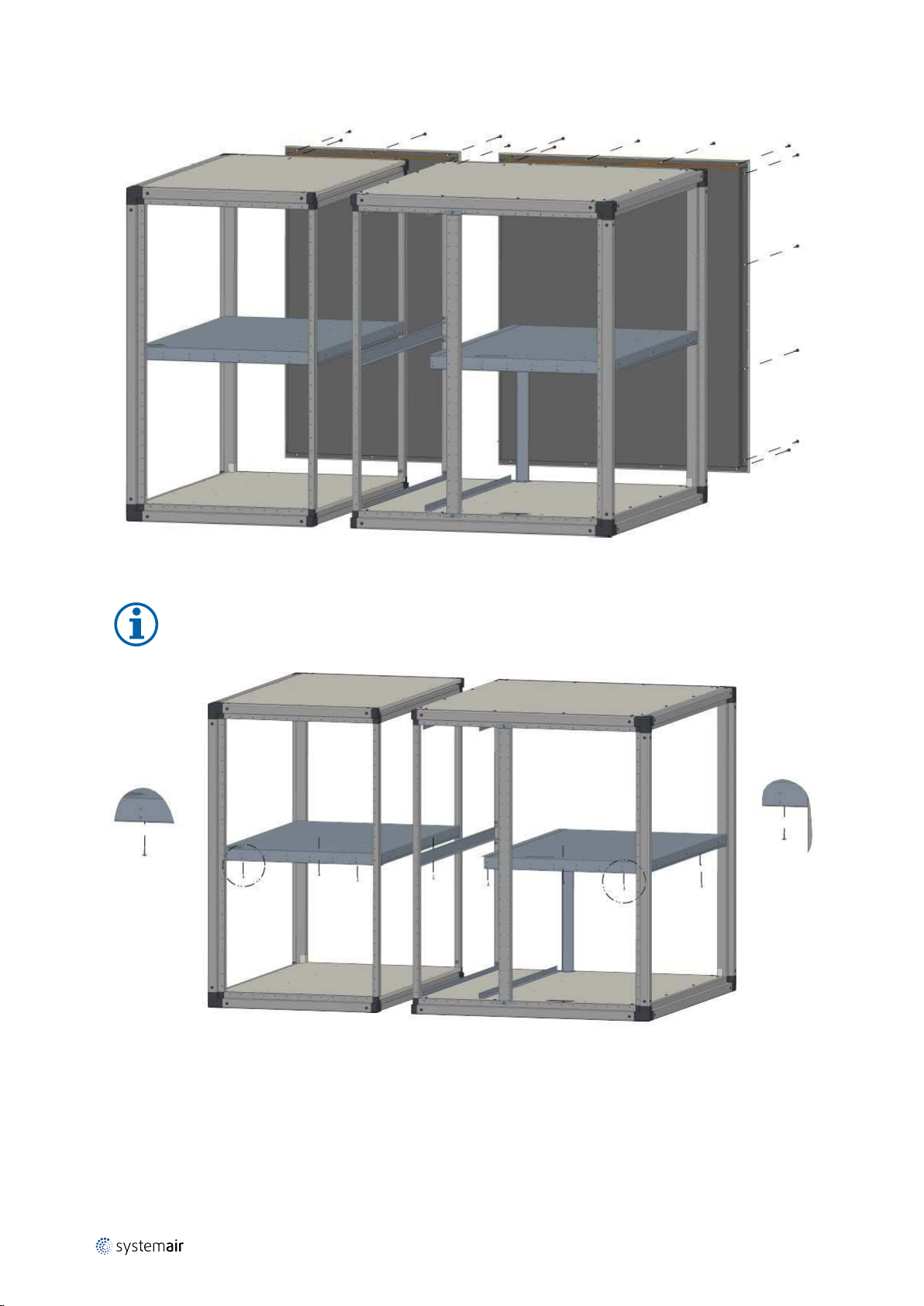
Remove the back panels.
Remove the screws from the horizontal partition panels.
Note:
Several screws are found on the underside.
output |
Page 6

Instructions for unloading at the site as well as installation and connection |
Remove the partition panels.
Remove the screws from the profiles that hold the partition panels.
33
Remove the profiles that hold the partition panels.
output |
Page 7
| Instructions for unloading at the site as well as installation and connection
34
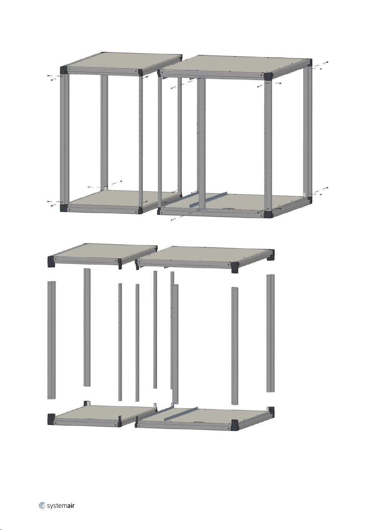
Remove the screws that fastened the vertical profiles to the plastic corners.
Remove the upper panels, as well as the profiles.
Separation is completed and all parts can be carried into the building.
I.1.10.3 Reassembly of the unit with fans, filters, dampers, rotary heat exchanger as well as
cabinet, cables, and control components
Reassemble the parts of the casing and reinstall the components in the opposite sequence of separation described
above.
output |
Page 8
Instructions for unloading at the site as well as installation and connection |
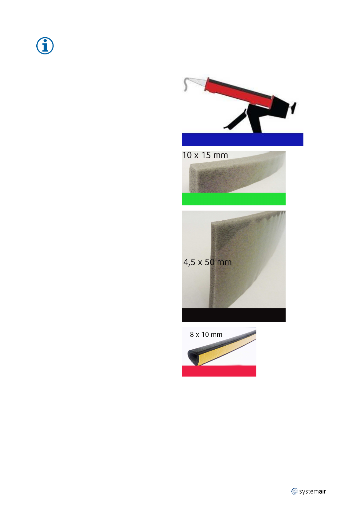
Note:
Application of the delivered mastic and placing of 3 different types of self-adhesive flexible sealing lists are
important in order to achieve the air-tightness that corresponds to Eurovent certified values for this air
handling unit.
This mastic must be applied to all connections between
vertical profiles and plastic corners and between the walls
with filters and the casing, between the walls with fans
and the casing, and around dampers. All places are
marked with blue colour on the unit. The number of
metres that must be applied appears from the table
below.
This is to some extent illustrated with blue colour in the
drawing below.
Place this self-adhesive sealing list on vertical edges that
are marked with green colour on the unit. This is illustrated with green colour in the drawing below.
35
Place this self-adhesive sealing list on horizontal edges
that are marked with black colour on the unit. This is illustrated with black colour in the drawing below.
Place this self-adhesive sealing list on the profiles of one
of the sections to achieve fully air-tight connection between two sections. The profiles of the section are
marked with red colour. This is illustrated with red colour
in the drawing below.
output |
Page 9

| Instructions for unloading at the site as well as installation and connection
36
Illustration of where to apply mastic and where to place the above mentioned sealing lists in the air handling unit
The number of metres to which mastic must be applied.
Size of unit Unit with rotary heat exchanger
16 18 m
18 20 m
20 22 m
output |
Page 10

Page 11

Page 12
Systemair
Unit 28, Gravelly Industrial Park
Birmingham, B24 8HZ
Systemair
Systemair A/S
Unit 02 Furry Park Ved Milepælen 7
Santry Dublin 9 DK-8361 Hasselager
Tel.: +44 (0)121 322 0200
info@systemair.co.uk
Tel.: +353 1 86 24 544 Tel.: +45 8738 7500
sales@systemair.ie mail@systemair.dk
www.systemair.co.uk www.systemair.co.uk www.systemair.dk
Geniox Core · User Manual · 90925520 · en_GB · · · output
 Loading...