

Page 1

Geniox
Air handling unit
User Manual
Document in original language |
GB
Part number of this manual 90925500
Order number output
Page 2

output |
Page 3

Detailed table of contents on the following pages
General description
A Manufacturer
B Name of machines
C Declaration of Conformity - example
D General descriptions, dangers and warnings
E Drawings, diagrams, guides and instructions for the use, maintenance and repair
F Employees in charge of operation/control/maintenance
G Intended use and range of applications
H Unintended use and misuse – inappropriate applications for the machine
Installation
I Instructions for unloading on the site as well as installation and connection
J Installation and assembly instructions for reduction of noise and vibration emissions
Start-up, adjustments and operation
K Start-up, adjustments, use, commissioning and unit in hipernation
L Information about the residual risks
M Instructions on the protective measures during repair and maintenance
N The essential characteristics of tools which may be fitted to the machinery
Machine stability
O The conditions of stability during use, transportation, assembly, dismantling when out of service
P Instructions for machinery where these are regularly to be transported
Breakdown
Q The operating method to be followed in the event of breakdown. Safe restart.
Maintenance
R Adjustment and maintenance operations
S Instructions to enable adjustment and maintenance safely
T The specifications of the spare parts to be used, when these affect the health and safety of operators
Noise
U Information on airborne noise emissions exceeding 70 dB(A)
Annexes
1 Declaration of conformity with production number (in separate cover)
2 Technical data – unique data for every unit (in separate cover)
3 Spare part list (in separate cover)
4 Assembly of base frame – height 118 mm for unit sizes 10 – 18
5 Assembly of base frame – height 118 mm for unit sizes 20 – 31
6 Assembly of base frame – height 218 mm for unit sizes 10 – 18
7 Assembly of base frame – height 218 mm for unit sizes 20 – 31
8 Installation of steel roof in the sizes 10 – 31
9 Speed control for rotor and assembly of divided rotor
10 Reversible heat pump unit (in separate cover, if heat pump was delivered)
11 Menu for internal controller in the heat pump unit (in separate cover, if heat pump was delivered)
12 Connection of fan motor and set-up manual for frequency converter
13 Commissioning protocol – proposal (in separate cover)
14 Report with data from final functional test on the Systemair factory (in separate cover, if control system was
delivered)
15 Short description of main components in the control system
16 Wiring diagram (in separate cover, if control system was delivered)
17 Operator’s guide (how to use the Systemair control panel) (in separate cover, if control system was delivered)
output |
Page 4

Contents
A Manufacturer.......... . . . .. .. ............ . . . .. ............ . . . .. .. ............. . . .. ............ . . . ............. . . . . ............ . . . ............ . . . 1
B Name of machines . ............. . . . ............ . . . .. ............ . . . . .. ............ . . . ............ . . . .. .. .. ............ . . . ............. . . .. .. ...1
C Declaration of Conformity - example. . . . ............. . . . .. ............ . . . ............ . . . . .. ............. . . .. ............ . . . .. ............. 2
D General descriptions, dangers and warnings ... . . . . ............. . . . ............ . . . ............. . . . .. .. ............ . . . ............ . . . .. .. 3
D.1 Overview via pictograms on the inspection side of the unit ........ . . .. ............ . . . .. ............. . . . .. ............ . . . .3
D.1.1 Where are pictograms placed on the units.... . . . ............. . . . .. ............ . . . ............ . . . . .. ............ . . . 3
D.1.2 Weight of each section and production number – example for the Geniox unit ........... . . .. ............4
D.1.3 CE label — example for the Geniox unit . . ............. . . . ............ . . . .. ............ . . . . .. ............ . . . ........4
D.1.4 Pictograms for all available functions in the units .. . .. ............ . . . .. ............ . . . .. .. ............. . . .. .....5
D.1.5 Pictograms about warnings and dangers on the units . . . ............ . . . ............ . . . . .. ............. . . .. .....6
D.2 Data about the unit according to cards and labels in and on the unit ......... . . . .. .. .. ............ . . . ............ . . . .. .. 6
D.2.1 Machine card with unique data on every unit. . . . .. .. .. ............ . . . ............ . . . .. .. .. ............ . . . ........6
D.2.2 Label with data about the cabinet — example.... . . . ............ . . . ............. . . . . ............ . . . ............ . . . 7
D.2.3 Flowchart – example of the label placed on or with the cabinet . .. ............. . . .. ............ . . . .. .........7
D.2.4 Symbols in the flowchart and explanation about the symbols ........... . . . ............ . . . ............ . . . . .. .8
D.2.5 Example of label placed on or with the cabinet – Terminal plan for external components . . . . .. .......9
D.3 Hand terminal ..... . . . .. .. ............ . . . .. ............ . . . ............. . . . . ............ . . . ............ . . . .. .. .. ............ . . . ........9
D.4 Dimensions of the units . . . . ............. . . .. .. .. ............ . . . .. ............ . . . ............. . . . . ............ . . . ............ . . . .. .. 9
D.5 Ordinary automatically operation – only manual operation by new parameters..... . . . ............. . . . .. .......... 10
D.6 Warnings about dangers .. . . .. ............. . . . . ............ . . . ............ . . . .. .. .. ............ . . . ............ . . . .. .. .. .......... 10
E Drawings, diagrams, guides and instructions for the use, maintenance and repair.... . . .. ............ . . . . .. ............ . . . .. 10
F Employees in charge of operation/control/maintenance .. .. ............. . . .. ............ . . . .. .. .. ............ . . . ............ . . . .. 10
G Intended use and range of applications........ . . .. .. .. ............ . . . .. ............ . . . .. .. ............. . . .. ............ . . . ............. 10
H Unintended use and misuse – inappropriate applications for the machine ........... . . . ............. . . . .. ............ . . . ...... 11
H.1 Air handling unit in operation ....... . . . ............ . . . . ............. . . . ............ . . . ............ . . . . .. ............ . . . .. ....... 11
I Instructions for unloading on the site as well as installation and connection .......... . . . ............ . . . . .. ............. . . .. ... 11
I.1 Unloading on the site..... . . . .. .. ............. . . . ............ . . . ............ . . . . .. ............ . . . .. ............ . . . .. .. ............ . 11
I.1.1 Unloading by fork-lift truck . . ............ . . . .. ............ . . . .. .. ............. . . .. ............ . . . ............. . . . . ... 11
I.1.2 Unloading by crane . .. .. ............. . . .. ............ . . . .. .. ............. . . .. ............ . . . .. ............. . . . .. ....... 12
I.1.3 Transport of unit without base frame on the site. ........... . . . .. ............. . . . .. ............ . . . ............ . 12
I.1.4 Lifting a unit with straps......... . . . ............ . . . .. .. ............ . . . .. ............ . . . .. .. ............. . . .. .......... 12
I.1.5 Lifting a unit with preinstalled brackets on the base frame for lifting........... . . . .. .. ............. . . .. ... 12
I.1.6 Lifting a unit without base frame and legs but with preinstalled brackets for lifting. .. . . . ............. 12
I.1.7 Roof unit with PVC roof. .. ............ . . . . .. ............ . . . .. ............ . . . .. .. ............ . . . .. ............ . . . ...... 14
I.1.8 Roof unit with steel roof . . . . ............ . . . ............ . . . .. .. .. ............ . . . ............ . . . .. .. ............. . . . ... 15
I.1.9 Pre-assembly storage. ........... . . . ............ . . . . .. ............ . . . ............ . . . .. .. .. ............ . . . ............ . 15
I.1.10 Tilt less than 30˚ during transportation of the section with heat pump .... . . . ............ . . . . .. .......... 15
I.1.11 Transport of rotary heat exchanger — always in vertical position ........ . . . ............ . . . . ............. . . 15
I.2 Installation - mechanical ... . . . ............ . . . .. ............ . . . . ............. . . .. ............ . . . .. ............. . . . .. ............ . . 15
I.2.1 Free area in front of and above the unit ........ . . . ............ . . . .. ............. . . . .. ............ . . . ............ . 15
I.2.2 Supporting surface...... . . . ............ . . . ............. . . . .. .. ............ . . . ............ . . . .. .. ............. . . . ....... 16
I.2.3 Adjustable feet under legs or base frame and transport of sections.... . . . ............. . . . .. ............ . . 16
I.2.4 Base frame assembly . ............. . . . .. ............ . . . ............ . . . . .. ............. . . .. ............ . . . .. .. ......... 16
I.2.5 Base frames for outdoor units . . .. ............ . . . ............ . . . .. .. .. ............ . . . ............ . . . .. .. .. .......... 16
I.2.6 Outdoor units — support under the base frame of the unit ........... . . .. ............ . . . ............. . . . . ... 16
I.2.7 Installation on the site of unit sections at the base frame when sections are delivered on
pallets. . . . ............ . . . .. ............ . . . .. .. ............. . . .. ............ . . . .. .. ............. . . .. ............ . . . .. ....... 17
I.2.8 Joining the AHU sections . . . . ............ . . . ............. . . . . ............ . . . ............ . . . .. .. ............. . . . ....... 20
I.2.9 Fitting the ductwork .......... . . .. .. .. ............ . . . .. ............ . . . .. .. ............. . . .. ............ . . . ............. 22
I.2.10 Risk of stack effect by vertical ducts and wind pressure on louvers ....... . . .. ............. . . . .. .......... 23
I.2.11 Remove transport brackets – when spring mounts are installed..... . . .. ............ . . . . .. ............ . . . .. 23
I.2.12 Refitting of guards ....... . . . .. ............ . . . .. ............. . . . ............ . . . .. ............ . . . . .. ............ . . . ...... 24
I.2.13 Lock the doors by using the key........... . . . ............. . . . . ............ . . . ............ . . . .. .. .. ............ . . . .. 25
I.3 Installation - electrical ............ . . .. ............ . . . . .. ............ . . . .. ............ . . . .. .. ............ . . . .. ............ . . . .. .. .. 25
I.3.1 Description...... . . . ............. . . . .. .. ............ . . . ............ . . . .. .. ............. . . . ............ . . . ............ . . . . . 25
I.3.2 Wiring diagrams . . ............. . . . .. .. ............ . . . ............ . . . .. ............. . . . .. ............ . . . ............ . . . . . 25
I.3.3 Installation of mains power supply ...... . . . ............ . . . . .. ............ . . . ............ . . . .. ............. . . . .. ... 25
I.3.4 Electrical connection of components and functions. . . ............ . . . ............. . . . .. ............ . . . .. ....... 26
output |
Page 5

Contents
I.3.5 Lock the doors by using the key...... . . . . ............ . . . .. ............ . . . .. ............. . . . ............ . . . .. ....... 27
I.4 Installation – Pipes for water – hot and chilled, valves and drains . . ............. . . .. ............ . . . . .. ............ . . . .. 27
I.4.1 Description...... . . . ............. . . . .. .. ............ . . . ............ . . . .. .. ............. . . . ............ . . . ............ . . . . . 27
I.4.2 Pipe connections .. .. ............ . . . . .. ............ . . . .. ............ . . . .. .. ............. . . .. ............ . . . .. .. ......... 27
I.4.3 Possibility of extracting components from the unit ......... . . . . ............. . . . ............ . . . .. ............ . . 27
I.4.4 Pipe connections to batteries ............ . . . . ............ . . . ............ . . . .. .. ............. . . . ............ . . . ...... 27
I.4.5 Draining condensate water ......... . . . ............ . . . .. ............. . . . ............. . . .. ............ . . . . .. .......... 29
I.4.6 Draining condensate water from heat exchanger... . . . ............ . . . .. .. .. ............ . . . ............. . . .. .. . 29
I.4.7 Draining condensate water from cooling battery — .......... . . . ............ . . . ............. . . . . ............ . . 30
J Installation and assembly instructions for reduction of noise and vibration emissions . . . . ............ . . . . .. ............ . . . .. 31
K Start-up, adjustments, use, commissioning and unit in hipernation . . . .. ............ . . . ............ . . . .. .. .. ............ . . . ...... 31
K.1 Print-outs on paper ........... . . . .. ............ . . . .. ............. . . . ............ . . . .. ............ . . . . .. ............ . . . ............ . 31
K.2 Electronic media.. . . .. ............. . . . .. ............ . . . ............. . . . .. .. ............ . . . ............ . . . .. .. .. ............ . . . ...... 31
K.3 Documentation is available for download . . ............ . . . ............ . . . . .. ............ . . . .. ............ . . . .. .. ............ . 32
K.4 Start-up by installer .. . . ............ . . . .. .. ............ . . . .. ............ . . . ............. . . . . ............ . . . ............ . . . .. .. .. ... 32
K.4.1 Checklist, relevant values .. . ............ . . . .. .. ............. . . .. ............ . . . .. ............. . . . ............. . . .. ... 32
K.5 Adjustments and use..... . . . ............. . . .. ............ . . . . .. ............ . . . ............. . . .. .. .. ............ . . . .. ............ . . 33
K.6 Description of functions ..... . . . .. ............ . . . .. .. ............. . . .. ............ . . . ............. . . . . ............ . . . ............ . 33
K.6.1 Remote control .. ............ . . . .. .. ............. . . .. ............ . . . ............. . . . . ............ . . . ............. . . .. .. . 33
K.6.2 Extended operation and external start/stop (for example by presence detectors) . .. ............ . . . .. 33
K.6.3 Valve and valve motor for heating coil....... . . . .. ............ . . . . .. ............ . . . ............ . . . .. .. .. .......... 33
K.6.4 Valve and valve motor for cooling coil .......... . . . ............. . . . .. ............. . . .. ............ . . . .. .. .. ....... 33
K.6.5 DX cooling........... . . . . .. ............. . . .. ............ . . . .. .. ............. . . .. ............ . . . .. ............. . . . .. ....... 33
K.6.6 Circulation pump, heating ... . . .. ............ . . . . .. ............ . . . ............. . . .. .. .. ............ . . . .. ............ . . 33
K.6.7 Fire alarm function . . ............. . . . . ............ . . . ............ . . . .. .. .. ............ . . . ............ . . . .. .. .. .......... 34
K.6.8 E tool - configuration tool ........ . . . ............ . . . .. .. ............. . . . ............ . . . ............ . . . . .. ............ . 34
K.6.9 Electrical heater battery . . ............ . . . . .. ............ . . . .. ............ . . . .. .. ............ . . . .. ............ . . . .. .. .. 34
K.6.10 Speed control of fans .......... . . . .. ............ . . . . .. ............ . . . ............ . . . .. .. .. ............ . . . ............ . 34
K.6.11 Cabinet .. . . .. .. ............ . . . ............ . . . .. .. .. ............ . . . ............ . . . .. ............. . . . .. ............ . . . ...... 35
K.6.12 Temperature sensors . ............ . . . .. .. ............. . . .. ............ . . . ............. . . . . ............ . . . ............ . 35
K.6.13 Damper motors.. . . .. ............. . . . . ............ . . . ............ . . . .. .. .. ............ . . . ............ . . . .. .. .. .......... 35
K.6.14 Filter guards . . . ............ . . . .. ............. . . . .. ............ . . . ............ . . . . ............. . . . ............ . . . .. ....... 35
K.6.15 Room temperature sensors......... . . . .. ............. . . . ............ . . . ............. . . . .. ............. . . .. .......... 35
K.6.16 Frost protection... . . . ............ . . . .. ............. . . . .. ............ . . . ............ . . . . .. ............ . . . .. ............ . . 35
K.6.17 Systemair Control Panel - SCP..... . . .. ............ . . . .. .. ............. . . .. ............ . . . ............. . . . . .......... 36
K.6.18 Cooling recovery ............ . . . .. .. .. ............ . . . ............ . . . .. .. .. ............ . . . ............ . . . .. .. ............ 36
K.6.19 Free cooling ....... . . . ............ . . . .. ............. . . . .. ............ . . . ............ . . . . .. ............ . . . .. ............ . . 36
K.6.20 Alarm signal . . .. .. ............ . . . ............ . . . .. .. .. ............ . . . ............. . . .. ............. . . . .. ............ . . . .. 36
K.6.21 Heat recovery...... . . . . .. ............. . . .. ............ . . . .. ............. . . . ............. . . .. ............ . . . . .. .......... 36
K.6.22 Frost protection – plate heat exchanger ... . . .. .. ............. . . . ............ . . . .. ............ . . . . .. ............ . . 36
K.7 Commissioning ....... . . . ............. . . . .. ............ . . . ............ . . . . .. ............ . . . .. ............ . . . .. .. ............. . . .. ... 36
K.8 Unit in hipernation ........ . . . ............. . . . .. .. ............ . . . ............ . . . .. .. .. ............ . . . ............ . . . .. .. .. .......... 36
L Information about the residual risks........... . . . ............ . . . .. ............. . . . .. ............ . . . ............ . . . . .. ............. . . .. ... 36
L.1 Unit casing ........... . . . .. .. .. ............ . . . ............ . . . .. .. .. ............ . . . ............. . . .. .. ............. . . . ............ . . . .. 36
L.1.1 Design of the machine to make transport safe .......... . . . ............. . . . ............. . . . ............. . . .. ... 36
L.1.2 Common for all unit sections ............ . . . .. ............ . . . ............ . . . . ............. . . . ............ . . . .. ....... 37
L.1.3 Common for all unit sections by insufficient lighting .... . . . .. ............ . . . .. ............ . . . .. .. ............ . 37
L.1.4 Dampers......... . . . ............. . . .. ............. . . . .. ............ . . . ............. . . . .. .. ............ . . . ............ . . . .. 37
L.1.5 Attenuators. . . ............ . . . .. .. ............ . . . .. ............ . . . .. .. ............. . . .. ............ . . . .. .. ............. . . . 37
L.1.6 Filters ....... . . . . ............ . . . .. ............ . . . .. .. ............. . . .. ............ . . . .. .. .. ............ . . . ............ . . . .. 38
L.1.7 Plug fans . . . . .. ............ . . . ............ . . . .. .. .. ............ . . . ............ . . . .. .. .. ............ . . . ............. . . .. .. . 38
L.1.8 Batteries for heating . . . ............. . . .. .. .. ............ . . . .. ............ . . . .. .. ............ . . . .. ............ . . . .. .. .. 39
L.1.9 Heat pump units. . . . . ............ . . . .. ............ . . . .. .. ............ . . . .. ............ . . . .. .. ............. . . .. .......... 39
M Instructions on the protective measures during repair and maintenance .......... . . . .. .. .. ............ . . . ............. . . .. .. . 40
N The essential characteristics of tools which may be fitted to the machinery..... . . . ............ . . . . .. ............ . . . .. ....... 40
O The conditions of stability during use, transportation, assembly, dismantling when out of service ...... . . . . .. .......... 40
O.1 Installed reliable to avoid units to be tilted or moved by storm. . . . ............. . . . .. ............ . . . ............. . . . .. .. 40
O.2 Transport of section with heat pump unit.... . . . ............. . . .. ............ . . . . .. ............ . . . ............. . . .. .. ........ 40
O.3 Disposal of the heat pump system - type Geniox - HP ............ . . . ............ . . . ............. . . . . ............ . . . ...... 41
O.4 General disassembly – sharp edges. . . . ............ . . . .. ............. . . . .. ............ . . . ............ . . . . .. ............. . . .. ... 41
P Instructions for machinery where these are regularly to be transported ...... . . . ............. . . . .. ............ . . . ............ . 41
Q The operating method to be followed in the event of breakdown. Safe restart. . . . ............ . . . ............. . . .. .. ........ 41
R Adjustment and maintenance operations .. . . . . ............ . . . .. ............ . . . .. .. ............. . . .. ............ . . . .. .. .. ............ . . 41
R.1 Shutdown of the unit to a safe state ........ . . .. ............. . . . .. ............ . . . ............. . . . .. ............. . . .. .......... 41
R.2 Unlock and lock the doors by using the key .......... . . .. ............ . . . .. .. .. ............ . . . ............ . . . .. .. .. .......... 42
R.3 Recommended maintenance intervals.......... . . . . ............ . . . .. ............ . . . .. .. ............ . . . .. ............ . . . .. .. .. 42
output |
Page 6

Contents
R.4 Filters – always replace filters with new filters with the same characteristics to maintain SFP
value ... . . . .. ............ . . . ............ . . . .. .. .. ............ . . . ............. . . .. .. .. ............ . . . .. ............ . . . .. .. ............ . 43
R.4.1 Bag filters – the number of filters and sizes of frames .. . ............ . . . .. .. .. ............ . . . ............ . . . .. 43
R.4.2 Panel filters – the number of filters and the sizes of the frames ......... . . . ............ . . . .. .. ............ . 44
R.4.3 Bag filters . . ............ . . . ............. . . . . ............ . . . ............ . . . .. .. .. ............ . . . ............. . . .. .. .. ...... 44
R.4.4 Panel filters ........... . . . . ............. . . .. ............ . . . ............. . . . . ............ . . . ............ . . . .. .. .. .......... 47
R.5 Changing the Internal Battery in the controller .......... . . . ............. . . . .. ............ . . . ............ . . . . .. ............ . 47
R.6 Other functions to maintain .. . .. ............ . . . ............ . . . .. .. .. ............ . . . ............. . . .. .. ............. . . . .......... 48
R.6.1 The unit..... . . . . ............ . . . .. ............ . . . .. ............. . . . ............ . . . .. ............ . . . . .. ............ . . . ...... 48
R.6.2 Dampers............ . . . ............ . . . . .. ............ . . . .. ............ . . . .. ............. . . . ............ . . . .. ............ . . 48
R.6.3 Rotary heat exchanger . . . . .. ............ . . . . .. ............ . . . ............ . . . .. .. .. ............ . . . ............. . . .. .. . 50
R.6.4 Cross flow and counter flow exchanger . . .. ............. . . .. ............ . . . .. .. .. ............ . . . ............ . . . .. 51
R.6.5 Run-around heat exchanger.... . . . ............ . . . ............ . . . . .. ............ . . . .. ............ . . . .. .. ............ . 52
R.6.6 Heating coil ..... . . . ............. . . . . ............ . . . ............. . . .. ............. . . . .. ............ . . . ............. . . . .. .. 53
R.6.7 Plug fans .... . . . ............ . . . .. ............. . . . .. ............ . . . ............ . . . . ............. . . . ............ . . . .. ....... 54
R.6.8 Silencer.. . . . ............. . . . .. ............ . . . ............. . . . ............. . . . ............. . . .. ............ . . . . .. .......... 55
R.6.9 Outdoor air section .... . . . . ............ . . . ............. . . .. .. .. ............ . . . .. ............ . . . .. ............. . . . ...... 56
R.6.10 Heat pump unit .......... . . . ............ . . . ............. . . . . ............ . . . ............. . . .. .. .. ............ . . . .. ....... 56
S Instructions to enable adjustment and maintenance safely . . ............. . . .. .. .. ............ . . . .. ............ . . . .. ............. . . 57
S.1 Protective measures and additional protective measures. . .. ............ . . . ............. . . .. .. ............. . . . .......... 57
S.1.1 Necessary protection measures prior to start-up ......... . . .. ............ . . . .. ............. . . . .. ............ . . 57
S.1.2 Safe adjustment and maintenance ......... . . .. .. .. ............ . . . .. ............ . . . .. .. ............. . . .. .......... 58
S.1.3 Personal protective equipment for maintenance staff – health and safety. . . . ............. . . .. .......... 58
T The specifications of the spare parts to be used, when these affect the health and safety of operators .. . . . .......... 58
T.1 Spare parts - Mechanical .......... . . . ............ . . . ............. . . . .. .. ............ . . . ............ . . . .. .. .. ............ . . . ...... 58
T.2 Spare parts - Electrical .. ............ . . . .. ............ . . . . ............. . . . ............ . . . ............ . . . . .. ............ . . . .. ....... 58
U Information on airborne noise emissions exceeding 70 dB(A) ........... . . .. .. .. ............ . . . .. ............ . . . .. ............. . . 58
Annex 1 Declaration of conformity with production number (in separate cover) .. . . . ............ . . . .. .. ............. . . . ......1-1
Annex 2 Technical data – unique data for every unit (in separate cover) .. . . . ............. . . . .. .. ............ . . . ............ . . . .2-1
Annex 3 Spare part list (in separate cover)... . . . ............ . . . .. .. ............. . . .. ............ . . . ............. . . . . ............ . . . .....3-1
Annex 4 Assembly of base frame – height 118 mm for unit sizes 10 – 18.......... . . .. ............ . . . . .. ............ . . . .. ......4-1
4.1 Base frame length 482 – 2564 [mm] Unit size 10 – 18 .......... . . .. .. .. ............ . . . .. ............ . . . .. .. ............4-2
4.2 Base frame length 2582 – 4964 [mm] Unit size 10 – 18 .. . .. .. .. ............ . . . .. ............ . . . .. .. ............. . . .. ..4-3
4.3 Base frame length 4982 – 6164 [mm] Unit size 10 – 18 .. . .. .. .. ............ . . . .. ............ . . . .. .. ............. . . .. ..4-4
Annex 5 Assembly of base frame – height 118 mm for unit sizes 20 – 31.......... . . .. ............ . . . . .. ............ . . . .. ......5-1
5.1 Base frame length 482– 2564 [mm] Unit size 20 – 31 .. . . . ............ . . . . .. ............. . . .. ............ . . . .. .. .. ......5-1
5.2 Base frame length 2582 – 4964 [mm] Unit size 20 – 31 .. . .. .. .. ............ . . . .. ............ . . . .. .. ............. . . .. ..5-2
5.3 Base frame length 4982 – 6164 [mm] Unit size 20 – 31 .. . .. .. .. ............ . . . .. ............ . . . .. .. ............. . . .. ..5-3
Annex 6 Assembly of base frame – height 218 mm for unit sizes 10 – 18 ..... . . . . ............ . . . ............ . . . .. .. ...........6-1
6.1 Base frame length 482– 2564 [mm] Unit size 10 – 18 .. . . . ............ . . . . .. ............. . . .. ............ . . . .. .. .. ......6-1
6.2 Base frame length 2582 – 4964 [mm] Unit size 10 – 18 .. . .. .. .. ............ . . . .. ............ . . . .. .. ............. . . .. ..6-2
6.3 Base frame length 4982 – 6164 [mm] Unit size 10 – 18 .. . .. .. .. ............ . . . .. ............ . . . .. .. ............. . . .. ..6-4
Annex 7 Assembly of base frame – height 218 mm for unit sizes 20 – 31.......... . . .. ............ . . . . .. ............ . . . .. ......7-1
7.1 Base frame length 482– 2564 [mm] Unit size 20-31 . . . . . ............ . . . ............ . . . .. .. .. ............ . . . ............7-1
7.2 Base frame length 2582 – 4964 [mm] Unit size 20 – 31 .. . .. .. .. ............ . . . .. ............ . . . .. .. ............. . . .. ..7-2
7.3 Base frame length 4982 – 6164 [mm] Unit size 20 – 31 .. . .. .. .. ............ . . . .. ............ . . . .. .. ............. . . .. ..7-3
Annex 8 Installation of steel roof in the sizes 10 – 31.. . . . ............. . . .. ............ . . . . .. ............ . . . ............. . . .. .........8-1
8.1 Overview. . . .. ............. . . .. ............ . . . .. .. .. ............ . . . ............ . . . .. .. .. ............ . . . ............ . . . .. .. ...........8-1
8.1.1 Mount rails. Units of size 10, 11, 12, and 14... . . . .. .. ............. . . .. ............ . . . .. ............. . . . .. ......8-1
8.1.2 Mount rails. Units of size 16 and units larger than size 16....... . . . .. .. ............ . . . .. ............ . . . .. ...8-1
8.1.3 Roof overhang along the long sides of the unit . ............ . . . .. .. ............. . . . ............ . . . ............8-2
8.1.4 Calculation of the overhang at the ends of the unit. Mount overhang profile – G1. . .. ............ . . . . 8-2
8.1.5 Foam bands between rails and roof plates – mount roof plates.... . . . ............ . . . .. ............. . . . .. ..8-3
8.1.6 Foam bands between roof plates .. .. ............ . . . ............ . . . . ............. . . . ............ . . . .. ............ .8-3
8.1.7 Mount roof plates – some of them are overlapping by 2 ribs..... . . . . ............ . . . ............ . . . .. .. .. ..8-3
8.1.8 Mount overhang profile – G5 on the other end of the unit. . . .. ............ . . . .. .. ............. . . .. .........8-3
8.1.9 Mount side profiles and corners along the edges of the roof to protect persons... . . . ............ . . . .8-3
8.1.10 Apply sealing on plate joints to ensure water resistance. ...... . . .. ............ . . . .. .. .. ............ . . . .....8-3
Annex 9 Speed control for rotor and assembly of divided rotor ............ . . .. ............ . . . .. .. .. ............ . . . ............ . . . .9-1
9.1 Speed control .. ............ . . . .. .. .. ............ . . . ............ . . . .. .. .. ............ . . . ............. . . .. .. ............. . . . .........9-1
9.1.1 Selection of correct signal via the 8DIP switch levers ............ . . . ............ . . . . .. ............ . . . .. ......9-1
9.1.2 Indication of operation mode via red and green LED as well as test of motor. . . . .. .. .. ............ . . . .9-2
9.1.3 Copy of the label with information about connection of cables.......... . . . ............ . . . ............ . . . . 9-3
9.2 Assemble the Systemair casing for Geniox 22, Geniox 24 and Geniox 27 ...... . . . .. ............ . . . ............ . . . . 9-3
9.3 Assemble divided rotor for Geniox 29 and Geniox 31... . . . ............ . . . .. .. .. ............ . . . ............. . . .. .. .. .....9-4
output |
Page 7

Contents
9.4 Installation of motor that turns rotor and sensor for rotation....... . . . .. .. ............ . . . ............ . . . .. .. .. .........9-4
Annex 10 Reversible heat pump unit (in separate cover, if heat pump was delivered) .. . . . .. ............ . . . ............ . . 10-1
10.1 Geniox-HP section (reversible heat pump unit) ... . . . . .. ............ . . . ............. . . .. .. .. ............ . . . .. ........... 10-1
Annex 11 Menu for internal controller in the heat pump unit (in separate cover, if heat pump was
delivered) .. . . ............ . . . . .. ............ . . . .. ............ . . . .. .. ............. . . .. ............ . . . .. .. .. ............ . . . ............ . . . .. .. .. 11-1
Annex 12 Connection of fan motor and set-up manual for frequency converter... . . . ............ . . . .. .. .. ............ . . . ... 12-1
12.1 Connection of fan motor .... . . . .. ............ . . . . .. ............ . . . ............ . . . .. .. ............. . . . ............ . . . .......... 12-1
12.2 Set-up for Danfoss FC101 for Geniox-units with AC motors . . .. ............ . . . ............. . . . .. ............ . . . .. .... 12-1
12.3 AC-fan operation without thermistor for Danfoss FC101. . ............ . . . .. ............ . . . . .. ............ . . . .......... 12-2
12.4 Set-up Danfoss FC101 for Geniox-units with PM motors......... . . . ............ . . . ............. . . . . ............ . . . ... 12-2
12.5 Installation ECblue ...... . . . .. ............. . . .. ............ . . . .. ............. . . . ............. . . .. ............ . . . . .. ............ . . 12-4
12.5.1 Connection. . . . ............ . . . . .. ............ . . . ............ . . . .. .. .. ............ . . . ............ . . . .. .. .. ............ . . 12-4
12.5.2 Diagnostic/faults . . . .. .. ............ . . . ............ . . . .. .. .. ............ . . . ............. . . .. .. .. ............ . . . .. .... 12-6
Annex 13 Commissioning protocol – proposal (in separate cover).. . . .. ............ . . . . .. ............ . . . ............. . . .. .. .. ... 13-1
Annex 14 Report with data from final functional test on the Systemair factory (in separate cover, if control
system was delivered) .. ............ . . . ............. . . .. .. ............. . . . ............ . . . ............. . . . .. .. ............ . . . ............ . . 14-1
Annex 15 Short description of main components in the control system . . . .. ............ . . . ............ . . . . .. ............. . . .. 15-1
15.1 Geniox units delivered in several sections ......... . . . ............. . . . .. ............ . . . ............ . . . . .. ............. . . .. 15-1
15.1.1 External components.... . . . .. ............ . . . .. .. ............. . . .. ............ . . . .. .. .. ............ . . . ............ . . 15-1
15.2 Geniox unit delivered assembled on base frame .. .. ............ . . . ............ . . . .. .. .. ............ . . . ............. . . .. 15-1
15.2.1 External components.... . . . .. ............ . . . .. .. ............. . . .. ............ . . . .. .. .. ............ . . . ............ . . 15-1
Annex 16 Wiring diagram (in separate cover, if control system was delivered) . .. ............ . . . ............ . . . .. .. .. ....... 16-1
Annex 17 Operator’s guide (how to use the Systemair control panel) (in separate cover, if control system was
delivered). . . . ............. . . . .. ............ . . . ............ . . . . .. ............ . . . .. ............ . . . .. .. ............. . . .. ............ . . . .. ........ 17-1
output |
Page 8

Page 9

Manufacturer |
A Manufacturer
This User Manual covers all air handling units with control system delivered by Systemair A/S.
Manufacturer and supplier data:
Systemair A/S
Ved Milepælen 7
DK-8361 Hasselager
Responsible for documentation: Ulf Bang
B Name of machines
This manual is about Systemair air handling units called Geniox 10, Geniox 11, Geniox 12, Geniox 14, Geniox 16, Geniox
18, Geniox 20, Geniox 22, Geniox 24, Geniox 27, Geniox 29 and Geniox 31.
1
output |
Page 10

| Declaration of Conformity - example
2
C Declaration of Conformity - example
The manufacturer:
Systemair A/S
Ved Milepælen 7
DK - 8361 Hasselager
Hereby declares that, air handling units of the flowing types:
DANVENT DV10, DANVENT DV15, DANVENT DV20, DANVENT DV25, DANVENT DV30, DANVENT DV40,
DANVENT DV50, DANVENT DV60, DANVENT DV80, DANVENT DV100, DANVENT DV120, DANVENT
DV150, DANVENT DV190 and DANVENT DV240.
TIMEec 10, TIMEec 15, TIMEec 20, TIMEec 25, TIMEec 30, TIMEec 40
Geniox: 10DR, 11DR, 12DR, 14DR, 16DR, 18DR, 20DR, 22DR, 24DR, 10SR, 11SR, 12SR, 14SR, 16SR,
18SR, 20SR, 22SR, 24SR, 27SR, 29SR, 31SR, 10DRR, 11DRR, 12DRR, 14DRR, 16DRR, 18DRR, 20DRR,
22DRR, 24DRR, 27SRR, 29SRR, 31SRR, 10MRR, 11MRR, 12MRR, 14MRR, 16MRR, 18MRR, 20MRR,
22MRR, 24MRR, 27MRR, 29MRR, 31MRR, 10.05/10.05TR, 11.055/11.055TR, 12.06/12.06TR, 14.07/
14.07TR, 16.08/16.08TR, 18.09/18.09TR, 20. 10/20.10TR, 22.11/22.11TR, 24.12/24.12TR, 27.13/
27.13TR, 29.14/29.14TR, 31.15/31.15TR, 10.05IR, 11.055IR, 12. 06IR, 14.07IR, 16.08IR, 18.09IR,
20.10IR, 22.11IR, 24.12IR, 27.13IR, 29.14IR, 31.15IR, 10DL, 11DL, 12DL, 14DL, 16DL, 18DL, 20DL, 22DL,
24DL, 10SL, 11SL, 12SL, 14SL, 16SL, 18SL, 20SL, 22SL, 24SL, 27SL, 29SL, 31SL, 10DLL, 11DLL, 12DLL,
14DLL, 16DLL, 18DLL, 20DLL, 22DLL, 24DLL, 27SLL, 29SLL, 31SLL, 10MLL, 11MLL, 12MLL, 14MLL,
16MLL, 18MLL, 20MLL, 22MLL, 24MLL, 27MLL, 29MLL, 31MLL, 10.05/10.05TL, 11.055/11.055TL,
12.06/12.06TL, 14.07/14. 07TL, 16.08/16.08TL, 18.09/18.09TL, 20.10/20.10TL, 22.11/22.11TL,
24.12/24.12TL, 27.13/27.13TL, 29.14/29.14TL, 31. 15/31.15TL, 10.05IL, 11.055IL, 12.06IL, 14.07IL,
16.08IL, 18.09IL, 20.10IL, 22.11IL, 24.12IL, 27.13IL, 29.14IL, 31.15IL
Serial No: ”YYMM-000XXXXXXX-XX”
are manufactured and delivered in accordance with following directives:
Machinery directive 2006/42/EC
Ecodesign — Commission regulation 1253/2014
EMC – directive 2014/30/EC
Low voltage directive 2014/35/EC
Pressure equipment directive 2014/68/EC
European Standard EN378–1 & 2 — 2016
Equipment type: Heat Pump Unit — Geniox and DVU Series
Consisting of: Compressor, evaporator and condenser
Verification and Assessment by:
Notified Body Bureau VERITAS CE0041 for PED
Bureau VERITAS UK, “Parklands”, Wilmslow Road
Didsbury, Manchester M20 2RE
The declaration is only valid, if the installation of the air handling unit is carried out according to the instructions delivered with the unit. The installer will be responsible for the CE marking and documentation, if any construction or functional changes are applied to the air handling unit.
Hasselager 15.08.2017
Module: A2
Certificate no:
CE-0041-PED-A2-SYA-001-17-DNK
output |
Page 11

General descriptions, dangers and warnings |
D General descriptions, dangers and warnings
Geniox air handling units are order specific machines available in thousands of different configurations. Only a few examples of machine configurations are described below. The air handling units are intended for the transport and treatment of air between -40 °C and + 40 °C.
The units are exclusively for comfort ventilation.
Maintenance of the units must be carried out by skilled technicians.
On the drawing below, a right hand unit is shown because the inspection doors are mounted on the right hand side of
the unit when looked in direction of SUPPLY airflow. The unit below is with rotary heat exchanger.
3
Position
A
B
C
D
Description
Connection, supply air (to the rooms)
Connection, exhaust air
Connection, outdoor air in
Connection, extract air (from the rooms)
D.1 Overview via pictograms on the inspection side of the unit
Symbol
D.1.1 Where are pictograms placed on the units
Example (Pictograms and labels with descriptions of functions for fast identification)
Position Description
1
2
output |
At each section a label with production number of this air handling unit as well as weight of
each section
Machine card
Symbol
Page 12

| General descriptions, dangers and warnings
4
Position Description
3
4
5
6
7
8
9
10 Damper – extract air
Damper - supply air
Filter - supply air
Fan- supply air
Heating battery - supply air
Fan - extract air
Heat exchanger
Filter – extract air
Symbol
11
Integrated control system in a cabinet behind this inspections door.
D.1.2 Weight of each section and production number – example for the Geniox unit
Weight of the section. Production number of the unit.
Number of the section in the unit.
Product name in this example Geniox 27SL, where 27 indicates the size of the unit. The unique production number for the complete unit in this example is 1712–
0004601640–10 where 17 indicates production year
2017 and 12 indicates month.
D.1.3 CE label — example for the Geniox unit
CE marking is printed on the machine card.
output |
Page 13
General descriptions, dangers and warnings |
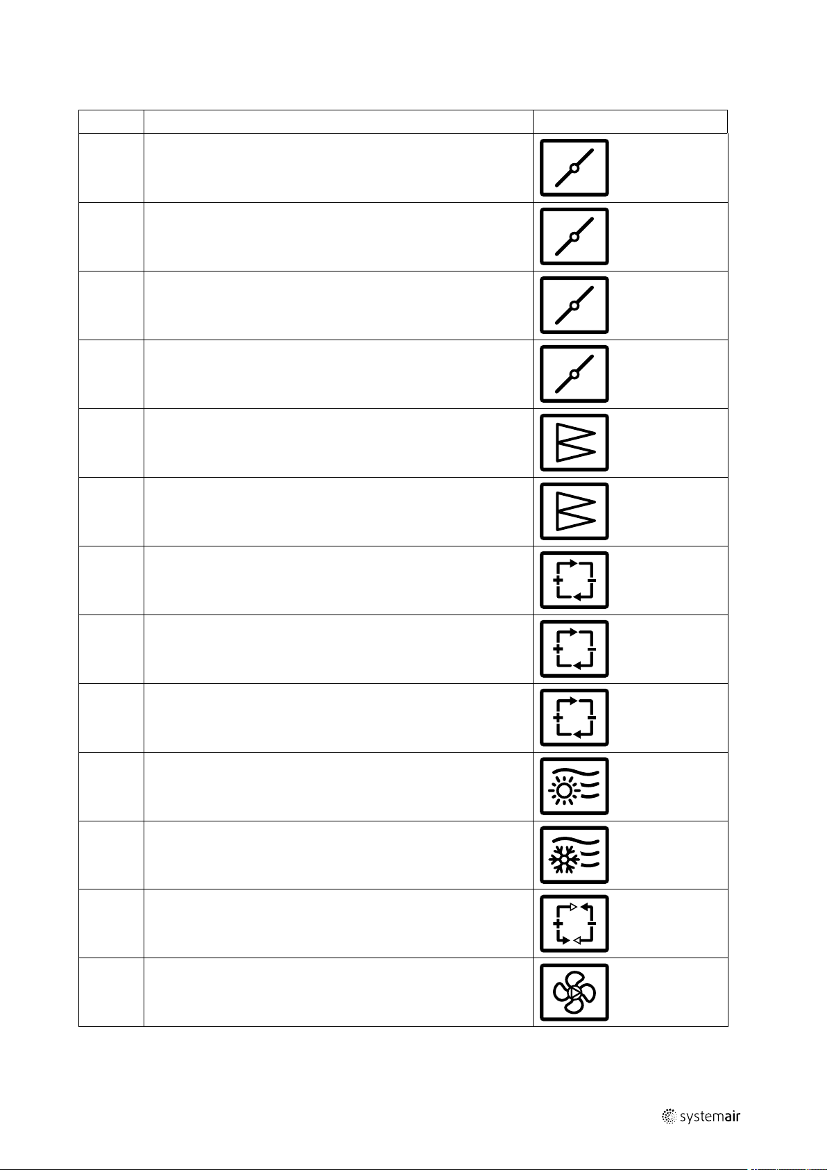
D.1.4 Pictograms for all available functions in the units
5
Id
GenioxA Damper
GenioxB Damper
GenioxM
GenioxP
GenioxG
GenioxF
Description
Damper for mixing
Damper for mixing
Panel filter
Bag filter
Symbol
GenioxC
GenioxQ
GenioxR
GenioxH
GenioxK
GenioxU Heat pump unit
Rotary heat exchanger
Plate heat exchanger (cross flow and counter flow)
Run around heat exchanger
Heating battery
Cooling battery
GenioxE
output |
Plug fan
Page 14
| General descriptions, dangers and warnings
6
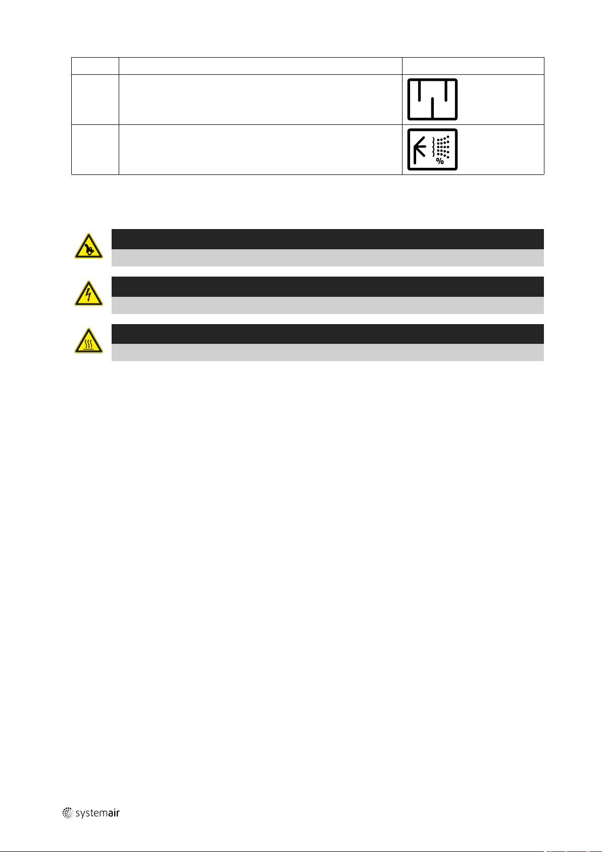
Id
GenioxD
GenioxX
Description
Silencer
Humidifier
D.1.5 Pictograms about warnings and dangers on the units
Pictograms according to EN1886 about
Warning
Warning about danger by rotating parts
Warning
Warning about danger by electricity
Warning
Warning about danger by heat
Symbol
D.2 Data about the unit according to cards and labels in and on the unit
D.2.1 Machine card with unique data on every unit
output |
Page 15
D.2.2 Label with data about the cabinet — example.
An example of the label that is always placed on or with
the cabinet
Systemair A/S
Systemair declares hereby that the cabinet is in
conformity with:
SBB Low voltage panels:
Electrical material on machines:
EMC-directive environment: 89/336/EOF
Diagram version Geniox ver. X:XX
Systemair order number
Unit size 10
Cabinet data:
System ground
Current type AC
Frequence 50 HZ
Rated voltage
Control voltage
PSCC max
PSCC min 650 A
Max fuse
Min fuse
Cable colors:
Protection circuit
230 VAC phase Black
0 VAC neutral Blue
24 VDC Grey
0 VDC Grey
Analog/digital
General descriptions, dangers and warnings |
N60439-1
EN60204-1
72800-1
TN-S
3*400 V+N+PE VAC
24 VDC
6 kA
25
10
Green/yellow
Grey
7
D.2.3 Flowchart – example of the label placed on or with the cabinet
output |
Page 16

| General descriptions, dangers and warnings
8
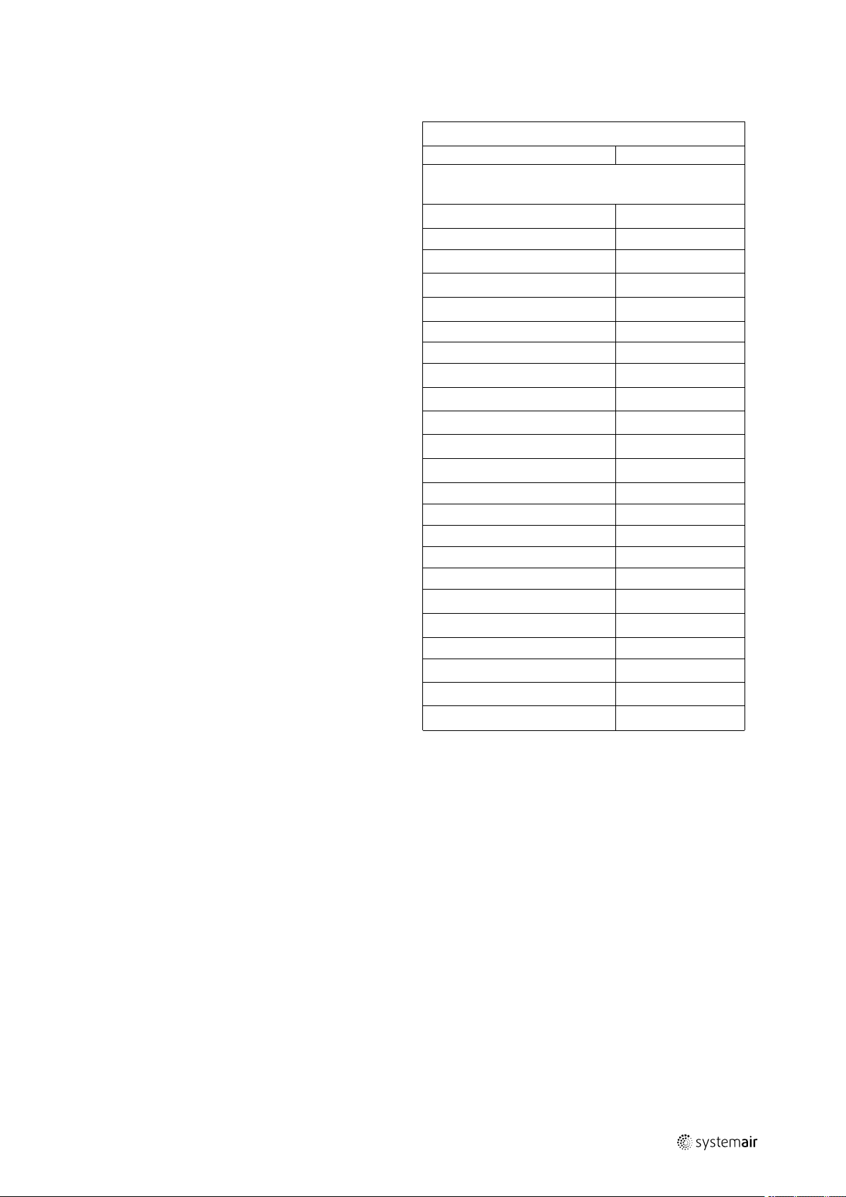
D.2.4 Symbols in the flowchart and explanation about the symbols
Id
T Temperature sensor - PT1000
M
M Damper motor – 0-10V
P
P Pressure transmitter – 0-10V
Description
Damper motor — on/off
Filter guard - digital
Symbol
RH
CO2
M
Sensor for relative humidity – 0-10V
Sensor for CO2 – 0-10V
Controller and drive motor for rotary heat exchanger – 0-10V
output |
Page 17

General descriptions, dangers and warnings |
D.2.5 Example of label placed on or with the cabinet – Terminal plan for external
components
9
D.3 Hand terminal
The hand terminal is delivered in a cardboard box containing the other external components. This cardboard box is usually, but not always, placed in the section with the supply air fan. The Operator’s Guide for the hand terminal is the Annex 17 attached to this – User Manual.
Important
All LEDs on the hand terminal must be off before startup of the unit.
1. ALARM: Press for alarm list
2. Alarm LED – red light for alarm
3. LED indicating change of parameters
4. OK/ENTER
5. Press for clear
6. Press for move of curser in menu
D.4 Dimensions of the units
See Annex 2 with information about the exact dimensions.
output |
Page 18
| Drawings, diagrams, guides and instructions for the use, maintenance and repair
10
D.5 Ordinary automatically operation – only manual operation by new parameters
The unit is operating fully automatically and manual operation includes only selection of new parameters via the buttons on the hand terminal. The hand terminal is connected by a cable to the controller in the cabinet. 10 meters of cable
is delivered with the unit and the customer has the possibility to replace this cable with an identical type of cable that is
up to 100 meters long. The alternative is that the controller is connected to a BMS system with the ability to select new
parameters via PC, tablet or SmartPhone.
D.6 Warnings about dangers
Pictograms according to EN1886 about
Warning
Warning about danger by rotating parts
Warning
Warning about danger by electricity
Warning
Warning about danger by heat
Warning
Disregards of instructions shown on warning signs are connected by risk for injury or damage on material.
E Drawings, diagrams, guides and instructions for the use, maintenance and
repair
All Geniox units with integrated control system are manufactured in compliance with the EC Declaration of Conformity
and they are CE marked as machines. Unique Declaration with production number of the machine is an integral part of
the machine – enclosed as Annex 1to this manual. If the buyer carries out changes or adds components in or on the machine, the buyer must issue a new EC Declaration of Conformity and a new CE marking of the machine.
To promote correct use of the machines, the below-mentioned instructions are an integral part of the machine:
• Unique drawings, data and description of functions for the delivered unit – Annex 2
• Wiring diagrams – Annex 16
• Operator’s Guide – Annex 17
• Instructions for use of the machine – chapter K in this manual
• Instructions about adjustment and maintenance – chapter R in this manual
• Safety during adjustment and maintenance – chapter S
F Employees in charge of operation/control/maintenance
The units are constructed and built with a fully integrated control system. After start-up and hand-over from installer to
operators, the unit operates fully automatically.
Indications of operating status as well as indication of faults are visible in the display and on the LEDs at the hand terminal. The operators can enter new parameters in the controller via the buttons on the hand terminal. Alternatively, the
controller can be connected to a BMS system so that new parameters can be selected via PC, tablet or Smartphone.
The operators do not need to open inspections doors for the operation.
Skilled technicians must carry care out maintenance as well as repairs.
G Intended use and range of applications
The air handling units are intended for the transport and treatment of air between -40 °C and + 40 °C The units are exclusively for comfort ventilation. The units are not for environments that exceed the corrosion class C4 according to EN
ISO 12944-2.
Intended applications for the units are:
output |
Page 19
Unintended use and misuse – inappropriate applications for the machine |
• Offices
• teaching rooms
• hotels
• shops
• homes and similar comfort zones
H Unintended use and misuse – inappropriate applications for the machine
Units for outdoor installation must be specified and ordered for outdoor installation. The units must not be used in environments that exceed corrosion class C4 according to EN ISO 12944-2, and for transport of solid particles.
Examples of not intended use:
• Kitchen extraction
• swimming pools
• off-shore
• Ex-areas
• drying of washed clothes.
• Do not use the unit with partly finished duct systems.
• Do not use the unit for ventilation of the building site until the unit is properly provided with guards.
11
H.1 Air handling unit in operation
The pressure difference between interior and exterior of the unit must not exceed 2000 Pa for the Geniox 10 and up to
Geniox 31 (including Geniox 31), and 1500 Pa for Geniox 36 and Geniox 44.
Before start-up of the unit all ducts, safety guards and all protective devices must be mounted to prevent any access to
rotating fan impellers. All inspection doors must be closed and locked when the unit is in operation.
Do not use the unit without filters.
I Instructions for unloading on the site as well as installation and connection
I.1 Unloading on the site
The air handling unit – AHU - is delivered as one section or in several sections, which are to be assembled on site. The
AHU is delivered on transport pallets, legs or on a base frame. Loading and unloading as well as transport on the site is
possible by fork-lift truck or by crane using suitable lifting straps.
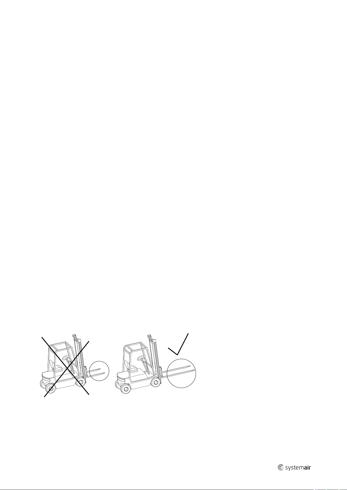
I.1.1 Unloading by fork-lift truck
The forks of the truck must be sufficiently long to avoid any damage to the AHU underside.
output |
Page 20
| Instructions for unloading on the site as well as installation and connection
12
I.1.2 Unloading by crane
AHU delivered on transport pallet must be lifted by straps as shown in the illustration.
I.1.3 Transport of unit without base frame on the site
Units without base frame are always delivered in sections with each section on a pallet. Sections can be transported on
the site by hand manual forklifts.
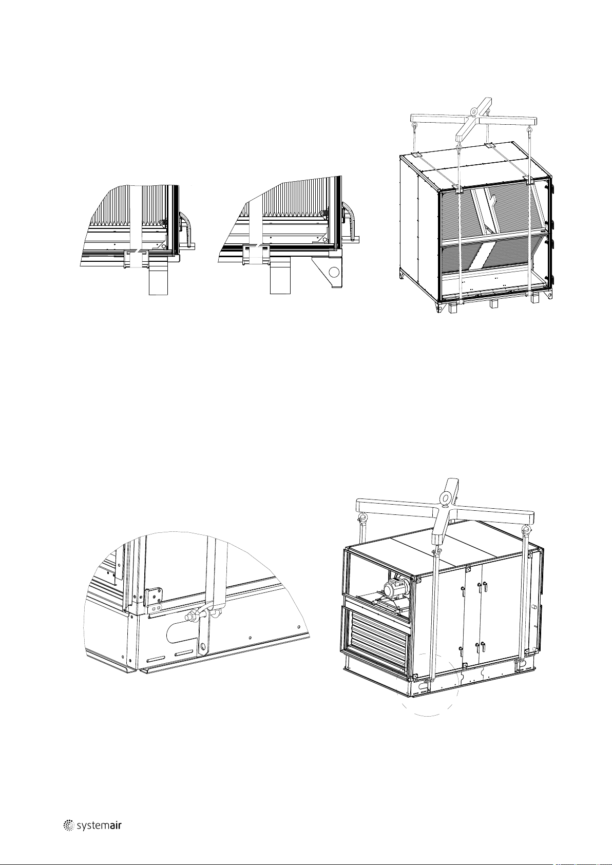
I.1.4 Lifting a unit with straps
Use an appropriate lifting beam with a sufficient span to avoid that the straps touch and damage the drip nose profiles
and the inspection side with handles, pipes and accessories – for example manometers, cabinets, tabs for measuring
the pressure.
I.1.5 Lifting a unit with preinstalled brackets on the base frame for lifting.
Lifting beam and straps are not included in the delivery.
I.1.6 Lifting a unit without base frame and legs but with preinstalled brackets for lifting.
Attach straps carefully to the 4 brackets at the bottom of sections on Geiniox units sizes 20 — 31, because those brackets are mounted to the profiles that are bearing the heavy components in the section
output |
Page 21

Instructions for unloading on the site as well as installation and connection |
This type of bracket at the bottom of Geniox units in the
sizes 20 to 31 is reinforced for lifting the unit. Mount a
shackel in each of the 4 brackets that should be suitable
for lifting the weight of the section. The weight of the
section is printed on the label placed on the inspection
side of the unit.
13
Caution
Do not lift the section in the 4 brackets at the top of the section, because those brackets are not mounted
on profiles that are bearing. The connection between these profiles at the top of the section is not designed
to lift the bottom of the section with the heavy components. There is a potential risk that the bottom with
the heavy components may fall down with serious risk of injury and damage to property.
Bracket at the bottom for lifting and assembling Geniox
units in the sizes 20 — 31
output |
Page 22

| Instructions for unloading on the site as well as installation and connection
14
Look at the backside of the bracket for lifting and assembling Geniox units in the sizes 20 — 31. Check that each
of the 4 brackets is mounted on the horizontal profiles by
screws with M6 mm thread and on the vertical profiles by
6 mm tap tights. Only brackets that are mounted in this
way are suitable for lifting.
This bracket at the bottom of Geniox units in the sizes 16
and 18 is not reinforced for lifting the unit. Furthermore,
this bracket is not firmly fastened for lifting the section.
This bracket is only for the assembly of sections.
I.1.7 Roof unit with PVC roof
Avoid damaging the drip nose profiles along the PVC roof. Keep the protection profiles of Styrofoam on the unit until
the installation has been completed. If the unit is lifted by straps, the straps must be kept away from the drip nose profiles by bars to avoid damage to roofing profiles.
output |
Page 23
Instructions for unloading on the site as well as installation and connection |
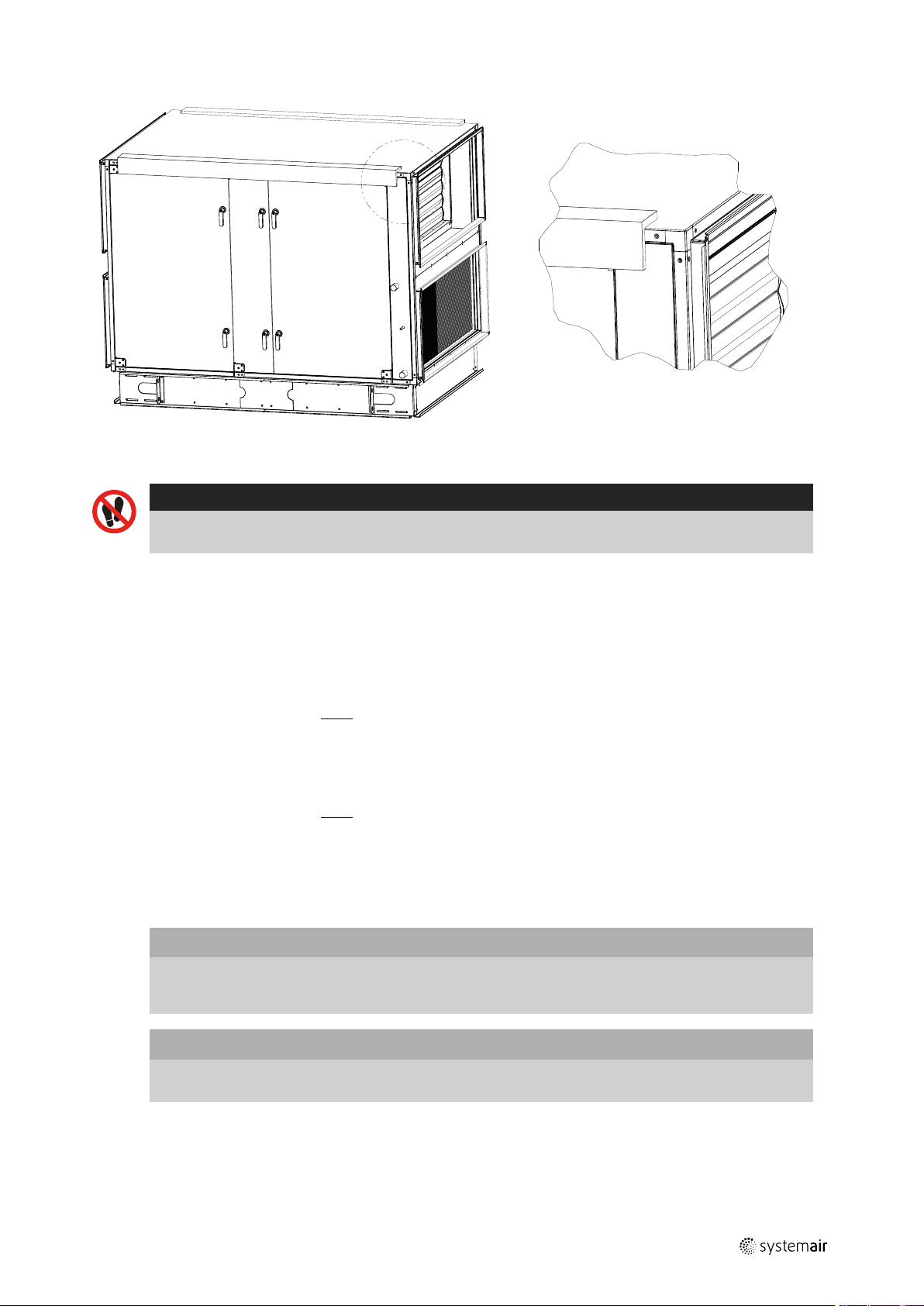
I.1.8 Roof unit with steel roof
Caution
For units with steel plate roof, the steel plates are delivered uninstalled on a separate pallet. Do not step or
walk on the plates.
15
I.1.9 Pre-assembly storage
The AHU must be protected from the weather and accidental impact. Plastic packaging must be removed and the unit
covered with tarpaulin or similar materials. In order to minimize condensation, sufficient air circulation must be ensured
between the covering and the unit.
I.1.10 Tilt less than 30˚ during transportation of the section with heat pump
During transportation, the unit section must always be in the upright position or tilted less than 30˚. If it is necessary to
tilt the unit more than 30˚, the suction pipe of the compressor must point upwards to prevent the escape of oil from the
compressor sump.
I.1.11 Transport of rotary heat exchanger — always in vertical position
During transportation, the unit section must always be in the upright vertical position and never in a horizontal or tilted
position. The rotary heat exchanger is not constructed for transportation in a horizontal or tilted position.
I.2 Installation - mechanical
I.2.1 Free area in front of and above the unit
Important
When positioning the unit on the site, it must be ensured that an area with the same width as the unit is
kept free for service and inspection and also for replacement of fans and exchanger, if needed. The width of
the free area must be at least 900 mm.
output |
Important
For safe access to the cabinet with electrical components, if the cabinet is placed on top of the unit, the free
area from the upper edge of the cabinet to the ceiling must be at least 700 mm.
Page 24
| Instructions for unloading on the site as well as installation and connection
16
I.2.2 Supporting surface
Caution
Duct work must be sound insulated and must not be mounted directly on beams, trusses or other critical
building parts.
Caution
The surface beneath the unit must be level, horizontal and vibration-free. The surface must be able to
withstand the load of the AHU. Weights of the sections are written in Annex 2.
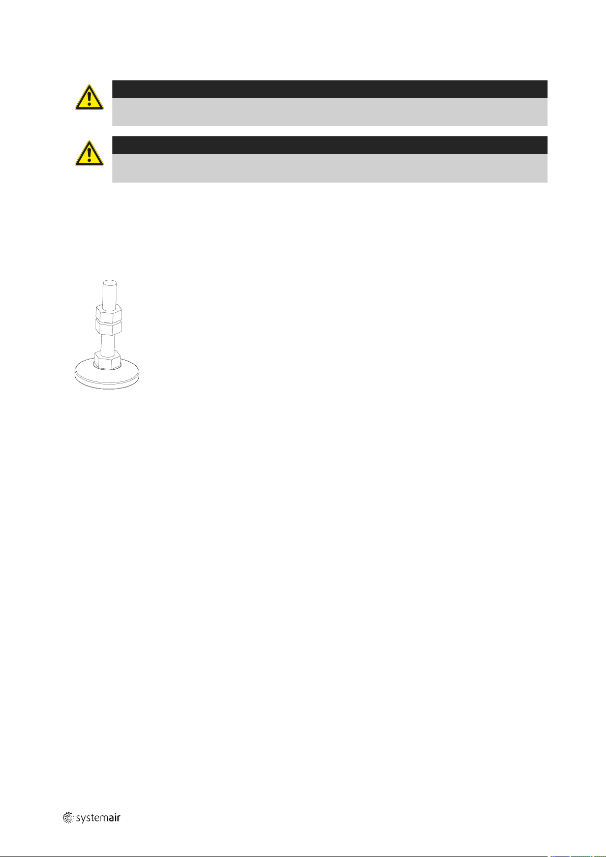
I.2.3 Adjustable feet under legs or base frame and transport of sections
Adjustable feet are provided in a carton box placed inside the unit. Adjustable feet are delivered for indoor units and
not for outdoor units.
Sections can be transported on the site by hand manual forklifts or similar. The frame profiles in the edges of the sections have carrying capacity for lifting by the hand manual forklifts.
I.2.4 Base frame assembly
Base frame is delivered unassembled for the indoor units that are delivered in sections on pallets. Assembly of the base
frame is illustrated on 4 pages in a manual in a plastic bag which is attached to one of the large base frame parts.
The 4 pages with the illustration regarding the assembly of the base frame are also available in this user manual in Annex 4, 5, 6 or7.
There are two types of base frames:
1. 118 mm high base frames
2. 218 mm high base frames
There are 4 different manuals and each of them illustrates the assembly of the 4 different types of base frames:
1. Manual about the 118 mm high base frames for AHUs in the sizes from Geniox 10 to Geniox 18. The name of this
manual is – Base frame 118 sizes10 - 18
2. Manual about the 118 mm high base frames for AHUs in the sizes from Geniox 20 to Geniox 31. The name of the
manual is – Base frame 118 sizes20 - 31
3. Manual about the 218 mm high base frames for AHUs in the sizes from Geniox 10 to Geniox 18. The name of the
manual is – Base frame 218 sizes10 - 18
4. Manual about the 218 mm high base frames for AHUs in the sizes from Geniox 20 to Geniox 31. The name of the
manual is – Base frame 218 sizes20 - 31
Mount adjustable feet with a distance of maximum 1500 mm between each foot under the base frame. The base frame
can now be levelled by the adjustable feet. The next step is to place and assemble AHU sections on the base frame.
I.2.5 Base frames for outdoor units
Outdoor units must be installed on 218 mm high base frames and are always fitted to the AHU sections. Hot-dip galvanized base frames are recommended for outdoor units. Systemair delivers these base frames without the above mentioned adjustable feet.
I.2.6 Outdoor units — support under the base frame of the unit
The installer must provide a frame that supports the base frame of the unit under the inspection side and under the
back side of the unit. The frame must support the base frames of the unit under the entire length of the unit.
output |
Page 25

Instructions for unloading on the site as well as installation and connection |
Caution
To avoid that the unit may tilt during storm the base frame of the unit must be properly fastened to the
frame provided by the installer
I.2.7 Installation on the site of unit sections at the base frame when sections are
delivered on pallets
17
Caution
It is strictly forbidden to lift a section under the top of the section. The plastic corners and brackets are not at
all reinforced for lifting the unit under the top. There is serious danger that the bottom with the heavy
components will fall down with the risk of serious injury and damage to property.
Lift up the section by hand manual forklifts to the level where the underside of the section is even with the overside of
the base frame.
Pull the section to the correct position on the base frame
by lifting straps – it is maybe necessary to support the
section by heavy duty furniture trolleys (see the photos
below)
Example of heavy duty furniture trolley turned with the
wheels upwards. Placed in this way on the forks of the
hand manual forklifts the heavy duty furniture trolleys are
suitable for safe and careful rolling of the unit sections
over the base frames.
output |
Page 26

| Instructions for unloading on the site as well as installation and connection
18
Example of very heavy duty furniture trolleys. Turned
with the wheels upwards and placed on the forks of hand
manual forklifts these heavy duty furniture trolleys are
very suitable for safe and careful rolling of the unit sections over to the base frames.
Pull sections together with a strap. We recommend the
shown type of strap because this type is not damaging
the frame profiles in the bottom of the units. An example
of strap is shown to the right. Note! Do not place the
strap on the vertical profiles because the plastic corners
and the profiles are not at all reinforced for the heavy
load and stress that is created by the tensioner when a
section is pulled along the base frame. To avoid any load
and stress on the plastic corners the strap must be carefully placed on the bottom profiles of the unit when sections are pulled together.
Note! Never — place the strap on the vertical profile too close to a corner, because the plastics corners and the profiles are not at all reinforced for the heavy load and stress created by the tensioner when a section is pulled along
the base frame or on the floor.
output |
Page 27

Instructions for unloading on the site as well as installation and connection |
Place the strap on the bottom profiles of the unit to avoid any load and stress on the vertical profiles when sections are
pulled together along the base frame. The sections must be pulled fully and tight together with the strap is placed on
the bottom profiles. Do not pull and slide a section unless the strap is placed on the bottom profile.
19
When the sections are pulled fully together it may be helpful to place the strap halfway up on the unit to press the sections fully together so that the rubber seals are closing 100% tight. Only gentle tension is allowed because the vertical
profiles are not reinforced for brutal stress in this direction and they may be bent.
output |
Page 28

| Instructions for unloading on the site as well as installation and connection
20
Sections are mounted to base frames with self-drilling screws. In the base frame you will find a sufficient number of 5
mm holes that are prepared for the self drilling screws. In this picture you are standing and you are watching the assembled base frame on the floor or roof.
Use self-drilling screws — 4,8 X 18 mm — to be screwed upward through the holes into the bottom profile of the air
handling unit Note! A screw must be placed in every hole to achieve the necessary strength. In this picture you are lying on the floor or roof looking upward under the base frame. The screws will not be visible, when you are standing beside the unit looking at the unit
I.2.8 Joining the AHU sections
The sections must be placed on the base frame and if the unit is delivered with 150 mm legs, the sections must be positioned directly in line with each other.
Ensure that the internal factory-fitted rubber sealing is undamaged
output |
Page 29

Instructions for unloading on the site as well as installation and connection |
The sections are then to be positioned directly opposite
each other. If the sections are built with legs, the adjustable feet can be used to get the sections in line and at the
same height.
Press the sections hard together so that the rubber profiles are so flat that the iron frames of the two sections
are joined. Strap with tensioner is suitable for pressing
the sections hard together.. Note! Do not place the strap
on the vertical profiles because the plastics corners and
the profiles are not at all reinforced for the heavy load
and stress created by the tensioner. To avoid any load
and stress on the plastic corners and the profiles the
strap must be carefully placed on the bottom profiles of
the unit.
21
The sections must then be locked permanently together
with 8 mm bolts and nuts. Bolts and nuts are not delivered from Systemair
output |
Page 30

| Instructions for unloading on the site as well as installation and connection
22
Assembly is done sucesfully
Bracket inside the unit for assembly of Geniox unit sections in the sizes 16 and 18
Bracket inside the unit for assembly of Geniox unit sections in the sizes 20 to 31
I.2.9 Fitting the ductwork
Flexible duct connections between AHU and ductwork must always be installed. Be sure that flexible duct connections
are almost fully stretched. (Flexible connections are ordered as accessories and they are placed inside the unit). At the
fan outlet on a centrifugal fan, the duct size should be as close to the outlet size as possible. Avoid blockage and turbulence at the fan outlet.
output |
Page 31

Instructions for unloading on the site as well as installation and connection |
I.2.10 Risk of stack effect by vertical ducts and wind pressure on louvers
Important
The Systemair air handling units can be ordered and delivered without dampers, and the installer/user must
check that duct systems with the described risk of stack effect (chimney effect) will be provided with
dampers and spring return motors.
On special occasions stack effect – also called chimney effect – in the ducts create airflows that drives the impellers by
turned off motors.
A rotating impeller is a potential hazard during cleaning and maintenance of the unit. Eliminate this airflow by dampers
with spring return motors for automatic closing of the dampers - even by power failure.
I.2.11 Remove transport brackets – when spring mounts are installed
I.2.11.1 Impeller diameters 220 – 560 mm
If the fans are installed on spring mounts the transport brackets must be removed after the installation of the air handling unit. Two transport brackets are fitted to the coil springs during transport and installation. Both transport brackets
must all be removed to give the full anti-vibration function to the coil springs. The transport brackets are made more
visible with yellow labels. After removal of the transport brackets they must be disposed of safely.
23
I.2.11.2 Impeller diameters 630 – 1.000 mm
If the fans are installed on spring mounts the transport brackets must be removed after the installation of the air handling unit. Four transport brackets are fitted to the coil springs during transport and installation. The four transport
brackets must all be removed to give the full anti-vibration function to the coil springs. The transport brackets are made
more visible with yellow labels, as shown in the picture below. After removal of the transport brackets they must be
disposed of safely.
output |
Page 32

| Instructions for unloading on the site as well as installation and connection
24
After disposal of the transport brackets the yellow label on the outside of the fan inspection door has no function and
should be removed.
I.2.12 Refitting of guards
The guard is a safety guard installed inside the door. Tools are necessary for the removal of the guard. If the guard has
been demounted during the installation on the site, the guard must be refitted before startup of the unit.
Use an Allan key — size 6 or size 8 — for refitting the
safety guard. Replace the vibration damping rubber list if
it is damaged.
output |
Page 33

Instructions for unloading on the site as well as installation and connection |
I.2.13 Lock the doors by using the key
Use the key to lock the doors. The doors are not locked
automatically by turning the handle to the vertical
position.
25
I.3 Installation - electrical
I.3.1 Description
The position of components is shown and described in Annex 2.
Connections to terminals are shown in the wiring diagram.
When control of constant pressure in the ducts (also called demand controlled capacity) is required, the pressure transmitters must measure in the duct system at places where all pressure changes can be registered accurately for reliable
pressure control. This placement is left to the customer’s free choice.
It is important to achieve a constant pressure – also for the most faraway diffusers.
I.3.2 Wiring diagrams
The wiring diagrams are printed in separate manuals delivered with the units.
The wiring diagrams are not unique for the order specific units, but it is standard wiring diagrams with data about all
configurations of the units. Hereby the wiring diagrams will inform about components that are not ordered and delivered. See the order confirmation and Annex 2 with exact information about the accessory components that are ordered
and delivered.
The wiring diagram includes:
• General description, Circuit diagrams, Cabinet layout, Terminal matrix and Cable plan.
• The wiring diagrams are on the DVD delivered with every unit.
I.3.2.1 Geniox units – labels on or with the cabinet
• Label with data about the cabinet – including data about fuses – see chapter D.2.2
• Flowchart – see chapter D.2.3– unique for the order specific unit – printed with the unique production number of the
unit
• Label with terminal plan for external components – see chapter D.2.5– standard, and not unique for the order specific
unit
I.3.3 Installation of mains power supply
An AC/DC residual current device must be installed in the power supply. The power supply for the units is 3*400 V + N
+ PE - 50 Hz. Protection of the units in accordance with the local statutory requirements for the additional protection of
systems with frequency converters and EC fans. The operator is responsible for the installation of the necessary protection equipment (supply disconnecting device is not delivered by Systemair.
output |
Page 34

| Instructions for unloading on the site as well as installation and connection
26
I.3.3.1 Necessary mains power supply for Geniox units with cabinet/control system
Necessary mains power supply is printed on the unique machine card placed on the front of every unit (see example of
a machine card in chapter D.2.1).
I.3.3.2 Necessary overvoltage protection device, that leads lightning overvoltage to an
earth lead on a safe way.
The Installer and user must be aware of the fact that lightning strikes make a risk that requires installation of overvoltage protection devices to lead the lightning overvoltage to an earth lead in a safe way. Installer and user must take care
of this according to local statutory requirements.
I.3.4 Electrical connection of components and functions
External components and functions are delivered according to the order confirmation. Cable numbers appear from the
label inside or on the cabinet, and cable numbers appear from the wiring diagrams.
I.3.4.1 Connection of the Systemair Control Panel to the Corrigo E28 controller
The SCP panel is provided with 10 metres of cable. Demount the cable at the back of the Systemair Control Panel - pull
the cable through the cable entry in the cabinet - and remount the cable in the panel, or add more cable – up to 100 m
of cable between the Systemair Control Panel and the controller is possible. Place the Systemair Control Panel on the
outer side of the unit or on a wall.
Position Description
1
2
3
4
5
6
7
8
9
10
11
12
13
Alarm button: Press for alarm list.
Alarm indicator: Flashing for unacknowledged alarm.
Write enable LED: Slow flashing indicates parameters can be changed.
OK button: Press to activate a selected menu/setting, if possible.
Button for clear: Abort a parameter setting or – if possible - restore the original value.
Right/left – and up/down buttons: Used for navigation up and down and to the right and left in the menu
tree. Up/down buttons are also used for increasing or decreasing values of parameters.
Holes for mounting
Terminal block
No cable on terminal 5 for software version 3.4 (illustrated with number 9 on the above drawing)
Brown cable on terminal 4 for software version 3.4 (illustrated with number 10 on the above drawing)
Yellow cable on terminal 3 for software version 3.4 (illustrated with number 11 on the above drawing)
White cable on terminal 2 for software version 3.4 (illustrated with number 12 on the above drawing)
Black cable on terminal 1 for software version 3.4 (illustrated with number 13 on the above drawing)
output |
Page 35

Instructions for unloading on the site as well as installation and connection |
I.3.5 Lock the doors by using the key
Use the key to lock the doors. The doors are not locked
automatically by turning the handle to the vertical
position.
27
I.4 Installation – Pipes for water – hot and chilled, valves and drains
I.4.1 Description
If ordered with the unit, the valves and valve motors are stored in a carton box placed inside the unit. Water trap(s) –
standard or optional - is (are) necessary to ensure escape of water from the tray under plate heat exchanger and (or)
cooling coil. Water trap(s) is (are) stored in a carton box placed inside the unit.
I.4.2 Pipe connections
Connection pipes on heating- and cooling coils are provided with external thread. Drainage outlets on drip trays are provided with straight pipe for quick connect fittings on the pipe with the water trap.
I.4.3 Possibility of extracting components from the unit
Pipes and cables must not obstruct the inspection doors and components which can be extracted from the unit. Potential components for extraction are filters, fans and rotary heat exchanger.
I.4.4 Pipe connections to batteries
I.4.4.1 Heating coils
Pipes for hot water must be protected by insulation against frost and loss of heat. Further protection against frost can
be obtained by installing electrical heating wires around the pipes and under the insulation combined with temperature
sensors and a control system. Pipes, insulation, electrical heating wires, control system for heating wires and circulation
pump are not delivered by Systemair.
I.4.4.2 Cooling coils
If ordered with the unit, the valves and valve motors are stored in a carton box placed inside the unit. Pipes for cooling
must be protected by insulation against condensation on the pipes and loss of cooling in the summer. Pipes and insulation are not delivered by Systemair.
I.4.4.3 Rigid pipe mounting brackets for valves, circulation pumps and pipe system
The coil and pipes from the coil are not constructed to withstand the weight and stress from valves, circulation pumps,
long pipes and insulation of pipes. The system must be supported carefully in rigid pipe mounting brackets to roof, floor
and walls.
I.4.4.3.1 Pipe connection to heating coils
The heating capacity of the coil with only 2 rows is independent of the connection of the hot water in equal flow or in
counter flow to the direction of the air, but connection of the hot water to the pipe marked for inlet and the return
output |
Page 36

| Instructions for unloading on the site as well as installation and connection
28
water to the pipe marked for outlet is very important to ensure that the sensor for transmission of the water temperature really will be placed in a return circuit of the coil (Screw-joint for the water temperature sensor is welded in the
main collection pipe for return water).
For the frost protection of heating coil, the water temperature in the coil is transmitted to the controller The controller
always generates a signal to the valve motor that keeps a sufficient flow of hot water to protect the coil against frost.
This frost protection is also activated when the running mode is “off”.
Coils with 3 rows or more must always be connected in counter flow to the airflow.
Note:
If glycol is added, the glycol must be without additives and auto glycol must not be used.Automatic bleeding
has to be installed at the highest point of the 2 pipes — supply or return pipe.
If the heating battery is built with 3 or more rows, the water flow must be in counter flow to the direction of the air.
To protect against frost a temperature sensor for the
transmission of an analog signal to the controller is placed
in a pipe on the collection pipe for return water. The sensor must be fitted water tight with a cap in the pipe before water under pressure is in the battery. The pipe for
the sensor is soldered on the collection pipe and it is important to hold contra on the pipe, when the cap is
tightened.
Battery seen from above. The sensor measures the
water temperature of the water inside one of the small
pipes for return water in the battery. The sensor reduces
the area in this pipe and hereby also the flow of warm
water in this pipe. The temperature in this pipe is reduced
more than the temperature in all other pipes by the airflow through the battery. Because the lowest temperature in the battery probably is measured here, this system
creates early and safe warning of frost.
It is important that the cap is tightened sufficient to keep
the sensor system fully water tight.
I.4.4.3.2 Pipe connection to cooling coils for chilled water
Coils with 3 rows or more must always be connected in counter flow to the airflow.
Caution
The glycol must be without additives and auto glycol must not be used.
Automatic bleeding has to be installed at the highest point of the 2 pipes — supply or return pipe
output |
Page 37

Instructions for unloading on the site as well as installation and connection |
I.4.4.3.3 Valve motor and valve for heating
The valve and valve motor are not installed. 2-way or 3-way valve is available.
I.4.4.3.4 Valve motor and valve for cooling
The valve and valve motor are not installed. 2-way or 3-way valve is available
I.4.5 Draining condensate water
Drip trays for collection of condensate water are installed under plate heat exchanger, run-around coil and cooling coil.
Each drip tray is provided with a drainage outlet. A water trap is always necessary. To avoid freeze ups and frost bursts
of water trap and pipes, sufficient insulation is recommended and installation of heating between the insulation and
water trap/pipes could even be necessary (insulation, heating and controller for the heating are not delivered by
Systemair).
I.4.6 Draining condensate water from heat exchanger
Condensate from the plate heat exchanger or run-around-coil is collected in the drip tray. Heavy negative air pressure
in this section prevents the water from flowing out of the drainpipe. A water trap with sufficient closing level of the
water is essential to ensure that condensate water flows out of the unit. The closing level of the water trap must be estimated correctly to ensure safe escape of the water (see the illustration and estimate the minimum closing level according to the table).The pipe diameter of the water trap and sewage system must be identical to the pipe diameter of
the drainage outlet from the tray.
Remember to check that there is water in the water trap.
Table 1 Negative pressure P (Pa)
29
P H1
Minimum
500 Pa 100 mm 40 mm 60 mm 10 mm
750 Pa 150 mm 55 mm 95 mm 20 mm
1.000Pa190 mm 70 mm 120 mm 20 mm
Necessary closing level that is H1 minus H2 — for example for the negative pressure 500 Pa — equal to 50 mm
of water column is 60 mm because the 50 mm corresponds to the negative pressure is lifting the water 50
mm and an excess height of 10 mm enables the water to
flow out through the water trap into the sewage system.
With the negative pressure at 750 Pa, an excess height of
20 mm enables the water to flow out through the water
trap into the sewage system.
H2 H1 minus
H2
Closing
level
Excess
height for
flow
output |
Page 38

| Instructions for unloading on the site as well as installation and connection
30
This type of water trap for sections with negative pressure and a ball that is sucked down into its seat for blockage of air flow into the section is available from
Systemair. The above-mentioned heights — H1 and H2 —
also apply to this type of water trap. The great advantage
of this type of water trap for sections with negative pressure is that this type does not require water at the bottom
to close for air flow backwards into the section. Condensate water will escape through this type of water trap —
even after long periods without any water to close for air
flow backwards through the trap.
This water trap is optional and must be ordered separately. Installation of water trap is not included.
The water trap in this picture has the delivered standard
length of H1 of 150 mm and with the adjustable length of
H2 adjusted to 55 mm, this set-up allows water to flow
out at a negative pressure of 750 Pa, because the closing
level that is H1 minus H2 is 95 mm and with 75 mm corresponding to the negative pressure lifting the water 75
mm and an excess height of 20 mm that enables the
water to lift the ball and to flow out through the water
trap into the sewage system..
H1 must be shortened on the site by the installer —
sometimes to only 100 mm — because the height of the
low version of the base frame is only 118 mm. The adjustable length of H2 must be reduced to the minimum of
40 mm. According to the values in the above table, this
allows Water to flow out at a negative pressure up to 500
Pa because the closing level that is H1 minus H2 is 60
mm with 50 mm corresponding to the negative pressure
lifting the water 50 mm and an excess height of 10 mm
that enables the water to lift the ball and to flow out
through the water trap into the sewage system.
To avoid freeze ups and frost bursts of water trap and
pipes, sufficient insulation is recommended and installation of heating between the insulation and water trap/
pipes could even be necessary (insulation, heating and
controller for the heating are not delivered by Systemair).
The insulation must be easy to remove above the cap, because the ball and the seat for the ball must be cleaned
regularly to allow the ball to close air-tight to the seat.
I.4.7 Draining condensate water from cooling battery —
If the cooling battery and the drip tray are placed in the unit where negative pressure (underpressure) occurs, the closing level of the water trap must be estimated correctly. See the above-mentioned information in I.4.6 Draining conden-
sate water from heat exchanger. If the cooling battery and the drip tray are placed in the unit where positive pressure
(overpressure) occurs, the closing level of the water trap must be estimated correctly as shown on the illustration below. A water trap is optional and installation of the water trap is not included.
output |
Page 39

Installation and assembly instructions for reduction of noise and vibration emissions |
Remember to check that there is water in the water trap.
Table 2 Positive pressure P (Pa)
P H1 Minimum H2
500 Pa 90 mm 65 mm
750 Pa 120 mm 90 mm
1.000 Pa 150 mm 120 mm
J Installation and assembly instructions for reduction of noise and vibration
emissions
Due to the design and construction of the units the (A) weighed sound pressure level from fans and other components
do not exceed 70 dB (A) outside the units.
Data about sound in Annex 2.
31
Installation of the units on springs will reduce the transmission of noise and vibrations to the building. Systemair does
not deliver springs for this purpose.
Flexible connections between the units and the ducts are available as accessories.
K Start-up, adjustments, use, commissioning and unit in hipernation
K.1 Print-outs on paper
The documents listed below are always printed on paper and delivered together with the units according to the Machinery Directive and the related national laws
This User Manual with:
• Declaration of incorporation – annex 1
• The unique technical data for this unit - Annex 2
• Installation instructions including instructions for the Danfoss frequency converter – Annex 4-12
• Printed form for Commissioning protocol - Annex 13
• Test report – Annex 14
• Short description about the main components in the control system – Annex 15
• Wiring diagrams - Annex 16
• Operator’s guide for the Systemair control panel - Annex 17
K.2 Electronic media
A DVD is delivered with every unit. The below-mentioned documents are available on every DVD and this means that
every DVD is provided with information about many components that are not delivered with every unit. The documents
on the DVD:
Common
• This User Manual
• Operator’s Guide
• Commissioning Protocol as a Word-file for modification by the installer
Components in the control system
• Danfoss frequency converter
• Corrigo controller manuals
• Information about Building Management Systems
output |
Page 40

| Start-up, adjustments, use, commissioning and unit in hipernation
32
• Damper motors
• Filter guards
• Temperature sensors
• Fire thermostats
• Smoke detectors
• Pressure transmitters
• Valves
• Valve motors
• Humidity sensors
• CO2 sensor
• Control panel
• Humidifier
• E-Tool software for fast communication with the Corrigo controller
• Other
K.3 Documentation is available for download
from https://techdoc.systemair.dk
Your local Systemair company is able to provide the data.
K.4 Start-up by installer
All protection and safety measures must be met before start-up of the unit. The mains supply voltage must also be
checked too. The mains supply voltage must be measured at the supply terminals in the cabinet.
K.4.1 Checklist, relevant values
K.4.1.1 Checklist prior to start-up
• Is the unit assembled correctly with its functions in the correct order? See Annex 2.
• Are the sections and ducts assembled correct? See annex i.
• Check that fans and anti-vibration mounts are not damaged after transportation and installation.
• Is the rotary exchanger turning freely?
• Are safety guards installed correctly?
• If the unit includes integrated heat pump, check whether it is installed and supervised by qualified service personnel.
• If the unit contains Electric air heater, make sure that the supply isolator disconnects with the unit.
• Ducts - are all ducts installed?
• External components - are the valve and valve motor installed correctly?
• Is the circulation pump installed correctly?
• Is water under pressure in the coil and circulation pump?
• Are the pressure transmitters installed and connected correctly? (If this is a system with pressure transmitters in the
ducts)
• Main power supply:
• Connected correctly? (3x400 V + N + PE)
• Test of supply voltage for actuators and control signal!
• Are control signals for actuators connected correctly?
K.4.1.2 Switch on power
Warning
Do not start until all safety procedures have been completed and ensure that inspection doors are closed
and locked.
output |
Page 41

Start-up, adjustments, use, commissioning and unit in hipernation |
Switch on power and the unit should be ready for the start-up.
For start-up see the Operator’s guide for the Systemair control panel - Annex 17 (this manual is delivered with the unit
– printed on paper and also available on the delivered DVD).
K.5 Adjustments and use
Adjust the factory set values for parameters on the Systemair Control Panel or via the software E-Tool on a PC. See the
Operator’s guide for the Systemair control panel - Annex 17 (this manual is delivered with the unit – printed on paper
and also available on the delivered DVD. Further information about the controller is available in the Corrigo E28 User
Manual that is available on the delivered DVD.
E-Tool software is also available on the delivered DVD and for download from a homepage.
K.6 Description of functions
K.6.1 Remote control
K.6.1.1 Communication to BMS systems with MODBUS
The controller has been prepared for communication via RS485 communication port to a MODBUS based BMS system
(Building Management System).
The controller can work as a stand-alone system without any support from other controllers.
33
K.6.1.2 Communication to BMS systems with LON
The controller has been prepared for communication via LON communication port to BMS systems (Building Management Systems).The port uses LonWorks according to the LonMark-guidelines. The LON-interface variables are available
from Systemair. The controller can work as a stand-alone system without any support from other controllers.
K.6.1.3 Communication to BMS systems via BACnet
The controller has been prepared for BACnet TCP/IP interface. This can be used for communication with a BMS system
(Building Management System).
The controller can work as a stand-alone system without any support from other controllers.
K.6.2 Extended operation and external start/stop (for example by presence detectors)
When the unit is running at reduced speed or is in shutdown mode, it can be forced up one step by using a Push button
(impulse). The required number of minutes for the extended operation must be selected on the Systemair Control Panel.
Button and cable are not delivered by Systemair. Furthermore when the unit is in shutdown mode it is possible to start/
stop the unit by presence detectors. Presence detectors and cable are not delivered by Systemair.
K.6.3 Valve and valve motor for heating coil
The supply voltage for the water valve actuator is 24V AC, the control signal is 0-10 V. The sensor for water temperature has to be installed in the heating coil and the sensor is provided with cable but not connected to the terminals in
the cabinet. The cable between valve motor and terminals in the cabinet is not delivered by Systemair. Standard valves
are available for 2 or 3-way connection.
K.6.4 Valve and valve motor for cooling coil
The supply voltage for the water valve actuator is 24V AC, the control signal is 0-10 V. Cables between valve motor
and terminals in the cabinet are not delivered by Systemair. Standard valves are available for 2 or 3-way connection.
K.6.5 DX cooling
A DX-cooler can be connected to the controller. Input and output are available for:
Start cooling – Alarm cooling – Cooling Y3. Cables are not delivered by Systemair
K.6.6 Circulation pump, heating
Circulation pump is not included in the delivery from Systemair. If the pump has not been activated for 24 hours, the
pump is exercised once daily for 1 minute to keep the pump in a good condition. Cables are not delivered by Systemair.
output |
Page 42

| Start-up, adjustments, use, commissioning and unit in hipernation
34
K.6.7 Fire alarm function
K.6.7.1 External fire signal that indicate block or run
The unit is available without components for this function. The controller is as standard configured for ordinary running
when the contact is closed (NC). By open contacts the fans stop and the dampers close. If disconnected, fire is indicated
and the unit will stop until the signal is re-connected. On the site qualified technicians are able to change the
configuration.
K.6.7.2 External fire signal
The unit is delivered without components for this function. The controller is as standard configured for ordinary running
when the contact is closed (NC). By open contacts the fans stop and the dampers close. When the unit has been shut
down by a fire signal, the unit has to be restarted on the control panel. On the site qualified technicians are able to
change the configuration.
K.6.7.3 Two fire thermostats
The unit is available with 2 thermostats installed in the unit – 1 in the extract air and 1 in the supply air. The cut-off temperature in the thermostats is adjustable between 40 and 70˚C. At the factory supply is set at 70˚C and extract is set at
40˚C. The controller is as standard configured to stop the fans and close the dampers if a thermostat is released. On the
site qualified technicians are able to change the configuration.
K.6.7.4 One smoke detector in extract air
The smoke detector has been installed in extract air next to the fan. The controller is as standard configured to stop the
fans and close the dampers if the detector is released by smoke. When the unit has been shut down by a fire signal, the
unit has to be restarted on the control panel. On the site qualified technicians are able to change the configuration.
K.6.8 E tool - configuration tool
The installer can download the PC software called E tool from www.regincontrols.com and this software enables the in-
staller to configure and supervise the function of the system via a graphic interface. This software displays all the parameters to be written in a commissioning report (the commissioning report is available as a Word-file on the DVD
delivered with the unit). The TCP/IP port in the Corrigo E28 controller is prepared for communication with the E tool
software.
K.6.9 Electrical heater battery
K.6.9.1 Control of heating capacity connected to unit with Systemair control system
Electrical heater installed with separate controller beside the heater. The separate controller is designed for capacity
conversion of the 0-10 V control signal from the main control system. The electric heater is not supplied from the air
handling unit cabinet as the cabinet is not designed to supply the heater with power. No power supply cables are connected to the electric heater. The separate controller is without supply disconnecting device.
K.6.9.2 Control of heating capacity connected to unit without Systemair control system
Electrical heater installed with separate controller beside the heater. The separate controller is designed for capacity
conversion of the 0-10 V control signal from the main control system. The heating capacity is adapted in steps.
The electric heater is not supplied from the air handling unit cabinet as the cabinet is not designed to supply the heater
with power. No power supply cables are connected to the electric heater. The separate controller is without supply disconnecting device.
K.6.10 Speed control of fans
K.6.10.1 Control system - frequency converters inside the unit are IP 20
Fan motor revolutions are controlled by frequency converters, and they are configured and tested to comply with the
data for the unit. The frequency converter for each fan motor is installed inside the unit beside the fan motor with cables between motor and converter. In units with complete control system the frequency converters are delivered with
system parameters adapted to the motors and the project.
K.6.10.2 Pressure transmitters
Separate control of the air flow or duct pressure for supply fan and for extract fan. The required air flow or duct pressures with normal as well as reduced capacity are selected on the Systemair Control Panel. The actual pressure is
output |
Page 43

Start-up, adjustments, use, commissioning and unit in hipernation |
measured by pressure transmitters. PI calculation in the controller continuously transmits the necessary revolutions for
the fans to the frequency converters to achieve the required pressure.
K.6.10.3 CO2-dependent air flow
The air flow is controlled by a CO2sensor. High CO2concentration is equal to higher air flow. Low CO2concentration is
equal to lower air flow. Based on the actual CO
of each fan is adjusted via frequency converter. Terminals in the cabinet are available for connection of the sensor.
level and a min/max level, the needed airflow is calculated. The speed
2
K.6.10.4 Humidity dependent air flow
The air flow is controlled by the humidity sensor. High humidity is equal to higher air flow. Low humidity is equal to lower air flow. Based on the actual humidity level and a min/max level the needed airflow is calculated. The speed of each
fan is adjusted via frequency converter. Terminals in the cabinet are available for connection of the sensor
K.6.11 Cabinet
K.6.11.1 Integrated cabinet in units with control system
Cabinet is integrated in the unit behind an inspection door. Terminals are installed in the cabinet for all external components. The number of terminals is always adapted to the individual order.
K.6.11.2 Cabinet placed on the unit with control system
The models with the cabinet on the unit are exclusively for indoor installation. Terminals are installed in the cabinet for
all external components. The number of terminals is always adapted to the individual order.
35
K.6.12 Temperature sensors
Four sensors are always delivered with each unit. See below where the sensors are placed;
• 1 sensor in the extract air, installed inside the unit
• 1 sensor in the outdoor air, installed inside the unit before the supply air filter on the cold side of the heat exchanger
• 1 sensor in the supply air to be placed in the supply air duct by the installer
• 1 sensor in the exhaust, installed inside the unit
K.6.13 Damper motors
Four different types of damper motors are available;
• On/off damper motor, without spring return function. Torque is 20 Nm and run time is 150 seconds
• Modulating damper motor, without spring return function. Torque is 20 Nm and run time is 150 seconds
• On/off damper motor, with spring return function. Torque is 20 Nm and run time is 150/16 seconds
• Modulating damper motor, with spring return function. Torque is 20 Nm and run time is 150/16 seconds
K.6.14 Filter guards
Filter guard over pre-filter and primary filter installed and connected to the controller for display of alarm when the mechanically set limit is exceeded. Filter alarm will be displayed on the Systemair Control Panel.
K.6.15 Room temperature sensors
One or two external room temperature sensors are available. The cabinet has been prepared with additional terminals
for connection of the room temperature sensors. The sensors are delivered without cable. The controller calculates an
average of the value from the 2 sensors as input for the control.
K.6.16 Frost protection
For the frost protection of the heating coil, the water temperature in the coil is transmitted to the controller by a temperature sensor in a water return circuit of the coil. The controller always generates a signal to the valve motor that
keeps a sufficient flow of hot water to protect the coil against frost. This frost protection is also activated when the running mode is “off”.
If the water temperature falls below the set point temperature the fans stop, the dampers close, and an alarm is
activated.
output |
Page 44

| Information about the residual risks
36
From Systemair every heating coil for hot water is provided with a little pipe at the collection pipe for the return water.
This little pipe is prepared for the installation of the above mentioned temperature sensor for the transmission of the return water temperature to the controller.
K.6.17 Systemair Control Panel - SCP
The separate cable-connected (10m) hand terminal with display and buttons – the Systemair Control Panel is always
necessary for the normal handling and programming, because the main Systemair E28 controller is without display and
buttons.
K.6.18 Cooling recovery
If the extract air temperature is lower than the outdoor air temperature, and there is a cooling demand in the rooms,
the cooling recovery will be activated by reversing the heat exchanger signal. The signal is increased to the cooling recovery by increasing cooling demand.
K.6.19 Free cooling
A temperature sensor has been installed inside the unit in the outdoor air entrance. If the outdoor temperature after
midnight is below the room temperature set point and the actual average room temperature is above the set point
temperature, the fans start during the summer to cool down the building during night hours.
K.6.20 Alarm signal
By alarm there are 24 V DC on terminals in the cabinet. Lamps and cables are not available from Systemair.
K.6.21 Heat recovery
The heat recovery capacity is controlled by modulating speed of the rotor.
K.6.22 Frost protection – plate heat exchanger
Signals from a temperature sensor mounted in the airflow after the plate heat exchanger are transmitted to the controller for frost protection of the plate heat exchanger.
K.7 Commissioning
When the installer has completed the installation and wants to hand over the finished installation to his customer for
payment the commissioning protocol can be the written receipt for the full ended job. Fill in the blank spaces and sign
the proposed commissioning protocol that is Annex 13, or fill in the Word-file with a Commissioning Protocol that is included on the DVD delivered with the unit.
K.8 Unit in hipernation
When the unit is in hipernation after the installer has completed the installation, the unit must be in operation for 10 —
15 minutes every day.
L Information about the residual risks
L.1 Unit casing
L.1.1 Design of the machine to make transport safe
Hazards/dangerous area:
• Incorrect handling during transportation may cause that the unit is dropped.
Dangerous incident:
• If a person is hit by a unit that is dropped, this could in unfortunate circumstances lead to irreversible injury or death.
Claim for reduction of danger:
• Correct handling during transportation is described in this manual. If lifted by fork-lift truck the forks of the truck
must be sufficiently long. Safety measures are also described in this manual by use of crane. Information about
weight of each section is also visible.
output |
Page 45

Information about the residual risks |
L.1.2 Common for all unit sections
L.1.2.1 Risk caused by surfaces, edges and corners
Hazards/dangerous area:
• Sharp edges on plates might occur inside the machines as well as sharp edges on frames of dampers. No sharp
edges on the outside of the units.
Hazards/dangerous area:
• Sharp edges on plates might occur inside the machines as well as sharp edges on frames of dampers. No sharp
edges on the outside of the units.
Dangerous incident:
• Cut fingers/hands.
Claim for reduction of danger:
• Risk only exists during maintenance and cleaning. This takes place at least once every year. Use of gloves and helmet is described in this manual. Cut-resistant gloves for protection against injury from sharp metal plate edges. Use
CE-marked gloves for this purpose. Lamps mounted inside the unit with sufficient lighting reduce the risk of injury.
L.1.3 Common for all unit sections by insufficient lighting
L.1.3.1 Risk caused by insufficient lighting inside sections
37
Hazards/dangerous area:
• On the floors of the units there are handles to hold filters, profiles for the carrying of fan motors. Cables are between
fan motors and frequency converters.
Dangerous incident:
• By insufficient lighting, the above-mentioned obstacles are not visible with the risk of stumbling that becomes a fall,
leading in unfortunate circumstances to irreversible injury or death.
Claim for reduction of danger:
• Risk only exists during maintenance and cleaning. This takes place at least once every year. According to this manual
and in the SystemairCAD software for configuration and selection of accessories, lamps for sufficient lighting inside
the units are mandatory according to the latest interpretations of the Machinery Directive by the authorities. Use of
helmets reduces the risk of injury.
L.1.4 Dampers
L.1.4.1 Risk caused by maintenance and cleaning of dampers
Hazards/dangerous area:
• Are between the damper blades and the system of bars and links between motor and damper blades.
Dangerous incident:
• Crushing of fingers.
Claim for reduction of danger:
• Examination is still under preparation in our own laboratory. Still no voluntary test persons are available.
L.1.5 Attenuators
L.1.5.1 Risk caused by maintenance and cleaning of attenuators
Hazards/dangerous area:
• High concentration of dust on the surface of the baffles might be harmful to the health.
Dangerous incident:
• To breathe in particles that is harmful to the health.
output |
Page 46

| Information about the residual risks
38
Claim for reduction of danger:
• Risk only exists during maintenance and cleaning. This takes place at least one time every year. Use of particulate
respirator is described in this manual. Particulate respirator – maintenance free including foam face-seal and adjustable pre-threaded headbands (same particulate respirator as recommended for change of filters).
L.1.6 Filters
L.1.6.1 Risk caused by missing change of filters
Hazards/dangerous area:
• Missing change of filters and missing maintenance decrease the capacity and final consequence will be breakdown.
Dangerous incident:
• By extensive lack of of filter change and maintenance the machine can break down.
Claim for reduction of danger:
• In the manual is the method and schedule for change of filters and maintenance specified.
L.1.6.2 Risk caused by the execution of filter change
Hazards/dangerous area:
• Filter panels and filter bags
Dangerous incident:
• To breathe in particles that is harmful to the health.
Claim for reduction of danger:
• Use of particulate respirator – maintenance free including foam face-seal and adjustable pre-threaded headbands
(same particulate respirator as recommended for cleaning of attenuators.
L.1.7 Plug fans
L.1.7.1 Risk caused by lightning strike
Hazards/dangerous area:
• Lightning strike close to the machine.
Dangerous incident:
• Lightning strike can create flash over between phases and conductive parts. This can cause fire or the overvoltage
can make injury on persons
Claim for reduction of danger:
• Installer and user must be aware of the fact that lightning makes a risk that requires installation of overvoltage protection devices to lead the lightning overvoltage to an earth lead on a safe way. The need for overvoltage protection
devices depend on where the unit is placed in and on the building.
• Installer and user must take care of this according to local statutory requirements. Overvoltage protection devices
are also described in chapter I.3.3.2 of this manual.
L.1.7.2 Risk caused by permanent magnet motor
Hazards/dangerous area:
• Rotation of the shaft generates electricity. This danger is always visualized by a yellow warning label on the inspection door where permanent magnet motors are installed.
output |
Page 47

Information about the residual risks |
Dangerous incident:
• Persons touching conductive parts get electric shock, burns, heart flicker and so on.
Claim for reduction of danger:
• By installation or repairs of conductive components, the shaft must be blocked to prevent any rotation.
L.1.7.3 Risk of rotating impeller caused by stack effect (chimney effect).
Hazards/dangerous area:
• On special occasions stack effect – also called chimney effect – in the ducts create airflows that drives the impellers
by turned off motors.
Dangerous incident:
• Injury of fingers, hands and arms.
Claim for reduction of danger:
• Eliminate this airflow for supply air and exhaust air by dampers with spring return motors for automatic closing of
the dampers by turned off fan motors and by power failure.
L.1.8 Batteries for heating
L.1.8.1 Extreme temperatures - heating
39
Hazards/dangerous area:
• Electrical heating elements can achieve surface temperature of 500 degree Celsius.
• Batteries and pipes for hot water can achieve 95 degree Celsius.
Dangerous incident:
• According to ISO 13732-1:2006, here is no direct risk of burns. (short-time contact – lesser than 2,5 sec).
Claim for reduction of danger:
• No.
L.1.8.2 Extreme temperatures - cooling
Hazards/dangerous area:
• Evaporator batteries and pipes connected to cooling compressor can achieve minus 10 degrees Celsius.
Dangerous incident:
• According to ISO 13732-1:2006, here is no direct risk of burns. (short-time contact – lesser than 2,5 sec).
Claim for reduction of danger:
• No.
L.1.9 Heat pump units
L.1.9.1 Risk of high temperature
Hazards/dangerous area:
• Condenser batteries and pipes can achieve temperature of 60 degree Celsius.
Dangerous incident:
• Vurderet ud fra ISO 13732-1:2006, der er umiddelbart ikke risiko for forbrændinger. (berøringstid 2,5 sek).
Claim for reduction of danger:
• No
output |
Page 48

| Instructions on the protective measures during repair and maintenance
40
L.1.9.2 Risk caused by lightning strike
Hazards/dangerous area:
• Lightning strike close to the machine.
Dangerous incident:
• Lightning strike can create flash over between phases and conductive parts. This can cause fire or the overvoltage
can make injury on persons
Claim for reduction of danger:
• Installer and user must be aware of the fact that lightning makes a risk that requires installation of overvoltage protection devices to lead the lightning overvoltage to an earth lead on a safe way. The need for overvoltage protection
devices depend on where the unit is placed in and on the building.
• Installer and user must take care of this according to local statutory requirements. Overvoltage protection devices
are also described in chapter I.3.3.2 of this manual
M Instructions on the protective measures during repair and maintenance
Use the below-mentioned personal protective equipment for maintenance:
• Cut-resistant gloves for protection against injury from sharp metal plate edges. Use CE-marked gloves for this
purpose.
• Helmet
• Particulate respirator – maintenance free including foam face-seal and adjustable pre-threaded headbands – for replacing filters.
• Padlock for locking the automatic circuit breakers in off position
• Permanent magnet motor. The shaft must be blocked during repairs and maintenance of the electric system (the
motor generates electricity by rotation – for example that the wind and thermic drives the fan/motor).
• Lighting inside the units. According to the latest interpretations of the Machinery Directive by the authorities sufficient lighting inside the units is mandatory.
• Tools to block the impeller during repairs and maintenance if stack effect – also called chimney effect – in the ducts
create airflows that drives the impellers by turned off motors
N The essential characteristics of tools which may be fitted to the machinery
The subject in the Machinery Directive about tools on the machine does not exist for the Geniox air handling units, because those tools does not exist.
O The conditions of stability during use, transportation, assembly, dismantling
when out of service
The unit must always be handled in an upright position. Never tilt any section more than 15 degrees. If sections must
be tilted more than 15 degrees, sections with fans or rotating exchangers that can be drawn out for service must be secured carefully.
During transportation, installation, dismantling or other handling, it must be secured that all components in the unit are
properly fastened and with additional attention to the control of anti-vibration mounts under the fans that they are undamaged. The mounting and smooth running of the fans must be controlled and handled with great care.
O.1 Installed reliable to avoid units to be tilted or moved by storm
Units installed on roofs and other places with the risk of heavy winds must be installed reliable to avoid that they can
be tilted or moved by the any storm. The base frame is provided with holes that are intended for fastening by sufficient
bolts and fittings supplied by the installer.
O.2 Transport of section with heat pump unit
Warning
During transportation, the unit section – GenioxU-HP must always be in the upright position or tilted less
than 30˚. If it is necessary to tilt the unit more than 30˚, the suction pipe of the compressor must point
upwards to prevent the escape of oil from the compressor sump.
output |
Page 49

Instructions for machinery where these are regularly to be transported |
O.3 Disposal of the heat pump system - type Geniox - HP
Prior to the disposal of the Geniox — HP unit section, the refrigerant in the heat pump system must be drained off by a
skilled technician from a certified company. After correct evacuation of the refrigerant, the disposal of the Geniox — HP
unit section is similar to the disposal of the rest of the air handling unit.
O.4 General disassembly – sharp edges
Pay attention to several sharp edges during dismantling and disposal of the unit. To avoid injury, CE-marked cut-resistant gloves as well as helmet must be used. The measures are described further in the Maintenance, Dismantling and
Disposal Manual.
P Instructions for machinery where these are regularly to be transported
The subject in the Machinery Directive about machinery that are regularly to be transported does not exist for the Geniox air handling units, because those units are specially made for one intended application.
Q The operating method to be followed in the event of breakdown. Safe restart.
Use the below mentioned procedure in the event of breakdown or blockage:
• Switch off the power and lock the automatic circuit breaker by padlocks in the off position.
• Remove the reason for breakdown or blockage.
• Follow the start-up procedure described in chapter K.
41
R Adjustment and maintenance operations
Must be performed by skilled technicians.
In connection with demands for compensation, Systemair must have full and unhindered access to all relevant reporting
on service, repair, modification and use since the unit was transferred from Systemair to a transport company at the
Systemair factory. It is a condition for compensation that maintenance outlined on the following pages has as a minimum been performed.
R.1 Shutdown of the unit to a safe state
Switch the unit to OFF on the Systemair Control Panel. See the - Operator’s Guide – Annex 17. Switch off the automatic
circuit breakers and block them by padlocks. The automatic circuit breakers are marked F1 to F4. See the illustration below about how to place a padlock on each automatic circuit breaker.
Check that the automatic circuit breaker marked F5 is still switched on because the lamps inside the unit, and only those
lamps, are connected to this switch. Switch on the lamps for light during the maintenance activities.
Use the start-up procedure described in chapter K, when the maintenance activities are completed.
output |
Page 50

| Adjustment and maintenance operations
42
R.2 Unlock and lock the doors by using the key
Use the key to lock the doors. The doors are not locked
automatically by turning the handle to the vertical
position.
R.3 Recommended maintenance intervals
Function Maintenance
Unit casing
Filters Change on demand by alarm and always minimum twice a year.
Fans
Rotary heat exchanger Check that leakage and dirt accumulation is insignificant
Plate heat exchanger Check bypass function and sequence for de-icing
Run-around heat
exchanger
Dampers
Hot water battery Check the dirt accumulation and clean, if needed.
Electric heating battery Check dirt accumulation and clean, if needed.
Cleaning of the unit casing.
Control of rubber seals on doors and between sections.
Control of rubber seals. Control of the system with lateral locking rails and
handles on Geniox10 – Geniox31. Control of the filter bank frames with
fasteners on Geniox36 and Geniox44.
Cleaning of all parts.
Check motors and bearings
Check that the impellers are rotating without dissonance.
Check that anti-vibration mounts are intact.
Check that the unit is operation without vibrations after the cleaning,
overhaul and maintenance.
Check that the rotor can turn freely and easily manually with a hand when
the belt is removed from the drive
Check the exchanger function and test the frost protection. The glycol must
be without additives and auto glycol must not be used.
Test the operation.
Visual inspection of seals and tightness when closed.
Bleeding, if needed.
Test of frost protection sequence
Test of cirkulation pump
Test the function of the system with the fuses for the safety.
Number
per year
1
1
2
2
1
1
1
1
1
1
1
1
1
1
1
1
1
1
1
1
output |
Page 51
Adjustment and maintenance operations |
43
Function Maintenance
Cooling battery Check dirt accumulation and clean, if needed.
Test the frost protection (glycol)
Heat pump unit
Condensate drain Cleaning of tray, water trap and outlet. Check the electrical heating between
Saving- and comfort
functions
Fire alarm Test of thermostats, smoke detectors and fire detection systems
Battery in controller Change the battery on demand by alarm in the display and always change
Remote control Test of Communications.
Mandatory annual control of the heat pump system. Must be done by
certified technician from a certified company.
insulation and pipes, if installed.
Test of CO2 sensor, humidity sensor, motion sensor, pressure transmitters
for air capacity control, extended operation via button, cooling recovery, free
cooling
the battery as a minimum every 5. Year.
Number
per year
1
1
1
1
1
1
1
1
R.4 Filters – always replace filters with new filters with the same characteristics to
maintain SFP value
Filters in supply air and in extract air always have the same sizes of frames and the number of filters for supply air and
extract air are always the same. REMEMBER to order filters for supply air as well as for extract air.
To maintain the factory-calculated SFP values for the air-handling unit, it is very important that filters with the same
characteristics for start pressure as well as lifetime replace factory-mounted filters.
To achieve the most favourable SFP values, the factory-mounted filters represent the lowest achievable start pressure
as well as the longest achievable lifetime. If other filters with higher start pressure and shorter lifetime replace the factory-mounted filters, the user will experience smaller airflow and/or consumption of more electricity, and the SFPv value calculated by Systemair according to the Eurovent certification will not be achieved. Poor SFPv values will be
detected by tests according to commissioning standards, DGNB, LEED or BREEAM sustainability standards and locally
defined performance standards (the SFPv is with new clean filters).
Filter frame for bag filters must be of NON-PVC plastic to ensure safe disposal by incineration.
For each individual air handling unit you will find the data for the factory-mounted filters in Annex 2 that is always provided in a cover placed inside the air handling unit when the air handling unit is delivered to the final site. Annex 2 is also always available from Systemair if you can inform us of the production number of the air handling unit. The
production number is always printed on the so-called machine card that is attached to the unit. You will find an example
of this machine card in section d.2.1 of this manual.
The factory-mounted filters comply with indoor air quality demands of customers and with the SFP values according to
local legislation.
These air handling units are available with filters that comply with the below-mentioned filter classes:
G4
M5
M6
F7
F7 CityFlo
F8
F9
R.4.1 Bag filters – the number of filters and sizes of frames
Filters in supply air and in extract air are always the same sizes and the same numbers. See the filters in supply or extract air below.
output |
Page 52

| Adjustment and maintenance operations
44
Size of unit
10
11
12
14
16
18
20
22
24
27
29
31
Numbers and sizes of frames for bag filters (WxH)
1x[792x392]
2x[490x490]
1x[592x490] + 1x[490x490]
2x[490x592] + 1x[287x592]
3x[490x592]
2x[490x392] + 4x[592x392]
3x[592x592] + 3x[287x592]
6x[592x490] + 2x[287x490]
3x[592x592] + 1x[490x592]+ 3x[592x490] + 1x[490x490]
2x[592x592] + 8x[490x592]
6x[592x592] + 4x[490x592]
5x[592x592] + 5x[490x490] + 5x[592x287]
Note:
Special sizes of filters are available from Camfil.
Dept of filter frame must be 25 mm to ensure a complete airtight sealing around the AHU filter frame
R.4.2 Panel filters – the number of filters and the sizes of the frames
Size of unit
10
11
12
14
16
18
20
22
24
27
29
31
Numbers and sizes of frames for panel filters (WxHxD)
1x[792x392x48]
2x[490x392x48]
1x[490x490x48] + 1x[592x490x48]
2x[490x592x48] + 1x[287x592x48]
3x[490x592x48]
2x[490x392x48] + 4x[592x392x48]
3x[592x592x48] + 3x[592x287x48]
6x[592x490x48] + 2x[287x490x48]
3x[592x592x48] 4x[490x592x48] + 1x[490x490x48]
2x[592x592x48] + 8x[490x592x48]
6x[592x592x48] + 4x[490x592x48]
5x[592x592x48] + 5x[592x490x48] + 5x[592x287x48]
Note:
Special sizes of filters are available by Camfil.
R.4.3 Bag filters
Turn the unit off and wait for 2 minutes till unit completely stops. Used filters can be pulled out. Store the used filters
immediately in plastic bags to avoid that dust pollutes the environment. Geniox units in the sizes 10 – 31 are provided
with a very corrosive-resistant and reliable system, where filters are slid into the units in a lower and upper durable uprofile of plastic/rubber Check the upper and lower U-profile for damage and check the vertical rubber profile on the
back wall as well as the rubber profile on the inspection door for damage. The new filter bags must be pushed carefully
into the unit in order to ensure that they are sealed properly. The filters must have vertical bags.
output |
Page 53

ONE self-adhesive foam strip must be placed on the vertical frame of EACH filter to avoid major air leakage through
the vertical opening between 2 filters. Please note – only
ONE self-adhesive foam strip must be placed on the vertical frame of EACH filter – Please establish the practical
rule that the self-adhesive foam strip is placed on the vertical side that is visible from the inspection side. Those
very important self-adhesive foam strips are usually not
delivered by the suppliers of filters. The customer must
order those self-adhesive foam strip from a supplier of
foam strips. Width of the foam strip is about 15 mm and
thickness of foam strip must be exactly 8 mm. If the thickness of the foam strip is less than 8 mm, there will be a
gap for leakage between the filters. If the foam strip is
more than 8 mm the row of filters in the U-profile will be
too wide making it impossible to close the inspection
door. Note! The staff must have the self-adhesive foam
strips available when they go to the air handling unit.
Without those self-adhesive foam strips, any change of
filters is impossible.
Remove the protection from the self-adhesive side of the
strip.
Adjustment and maintenance operations |
45
Place the self-adhesive strip on one vertical side of the
filter fame
Check that the end of the strip is fully even with the horizontal side of the filter frame.
output |
Page 54

| Adjustment and maintenance operations
46
Remove excess of the strip. The end of the strip must be
fully even with the horizontal side of the filter frame.
Push the filters carefully in the U-profile to be sure that
there are no leakages between the filters Check that the
vertical side of the last filter in the U-profile is fully even
with the end of the U-profile. If the end of the last filter is
not fully even with the end of the U-proflle an additional
self-adhesive profile must be added to avoid any gap between the rubber profile on the inspection door and the
last filter.
The end of the last filter is fully even with the end of the
U-profile. The rubber profile on the inspection door will
close the gap between inspection door and filter. Job is
done.
Check that rubber profiles on the back panel as well as
rubber profiles on the inspection door are without wear
and damage — still sufficient for avoiding any air leakage.
output |
Page 55

R.4.4 Panel filters
The filter cell guide rails are to be cleaned before fitting
the new filters.
R.5 Changing the Internal Battery in the controller
Adjustment and maintenance operations |
47
Caution
This procedure requires knowledge of proper ESD protection; i.e. an earthed wristband must be used!
When the alarm ”Internal Battery” is activated and the battery LED lights up red, the battery for backup of program
memory and real-time clock has become too weak. The battery is replaced as described below. A backup capacitor
saves the memory and keeps the clock running for at least 10 minutes after the power supply is removed. Therefore, if
the battery replacement takes less than 10 minutes, there will be no need to reload the program, and the clock will
continue to run normally.
The replacement battery must be of the type CR2032.
1 Remove the cover by pressing down the locking tor-
ques at the edge of the cover using a small screwdriver, and at the same time pulling the edges
outwards.
2 Grip the battery firmly with your fingers and lift it up-
wards until it rises from its holder. Press the new battery firmly down into place. Note that to preserve
correct polarity; the battery can only be inserted the
“right way round”.
output |
Page 56

| Adjustment and maintenance operations
48
R.6 Other functions to maintain
R.6.1 The unit
It is very easy to remove inspection doors for extraordinary good access to cleaning, service, repairs and replacement of components in the unit. Lift the stainless
steel shaft in the hinge to remove the door
The unit should be cleaned once a year when operating with normal air quality for comfort ventilation with no special
hygiene requirements.
To clean the unit, dry it off with a dry cloth, or use water mixed with a non-corrosive cleaning medium.
Any corrosion — for example the bottom of the section for outdoor air intake and the bottom of the section for exhaust
air outlet must be cleaned off immediately, and the surface treated.
In special operating conditions, where the air is aggressive or very humid, for example, or where there are special hygiene requirements, the unit shall be cleaned more frequently as required.
Cleaning medium and method should be adapted to the relevant conditions. Any corrosion should be cleaned off immediately, and the surface treated.
Closing mechanisms are to be lubricated at least once a year. Synthetic door hinges are service free. Seals around inspection doors are to be cleaned at least once a year and are to be checked for leakage.
It is recommended to treat the seals with a moisture repellent agent.
All seals are to be inspected at least once a year and are to be repaired if necessary.
Grilles for air intake and exhaust air outlet are to be cleaned at least once a year to prevent blockage.
R.6.2 Dampers
Rubber seals between the damper blades and the frame
are to be checked once a year. These seals are not to be
lubricated or treated in any other way.
output |
Page 57

Each damper blade is driven by a gear drive of a temperature-resistant, glass-fibre reinforced PA6 nylon composite. Gear-drive as well as bearings do not require
lubrication
Adjustment and maintenance operations |
49
The damper blades are fitted with synthetic bearings requiring no lubrication. Air-tightness of the damper, when the
damper motor is in the closed position, must be visually checked once a year. The damper motor is to be adjusted if the
damper does not close tightly.
output |
Page 58

| Adjustment and maintenance operations
50
R.6.3 Rotary heat exchanger
R.6.3.1 Rotor
The rotor is to be checked at least once a year to ensure that it can turn freely and easily. This can be done by removing
the belt drive at the motor and then turning the rotor manually with a hand on the peripheral rotor casing. At the same
time the brush seals are to be checked for damage. The bearings are factory lubricated and do not require any service
lubrication. During operation the rotor can become dirty. The rotor can be cleaned by blowing through with compressed
air.
To ease inspection and service the rotor can be pulled out of the sizes 10, 11, 12, 14 and 16.
R.6.3.2 Motor and belt drive
The bearings are factory lubricated and do not require any service lubrication. The belt drive is to be checked for correct
tightness and that it is undamaged. On smaller AHU, the rotor is fitted with an elastic belt drive and supplied with a reserve belt on the rotor. This belt drive does not require service and cannot be shortened. A new belt can be fitted using
specialist tools. On larger heat exchangers the rotor has a V-belt with a belt connector. If the belt is no longer tight, it
must be shortened to a length which enables the motor base frame tightening spring to hold the belt tight. If new
screws are used for the belt connector, they must not have a length which exceeds the thickness of the belt and connector. Remove the excess, if any, with a file.
output |
Page 59

Adjustment and maintenance operations |
R.6.4 Cross flow and counter flow exchanger
Note:
Once a year the edges of the heat exchanger plates are to be checked for cleanliness and damage.
If there is dust on the edges of the plates, remove it with a soft brush. If grease or other such substances are present,
then the edges must be washed using grease dissolving detergents.
51
R.6.4.1 By-pass damper
The damper blades are fitted with synthetic bearings requiring no lubrication. Each damper blade is driven by a gear
drive of a temperature resistant glass fibre reinforced PA6 nylon composite. The steel rods and brass bushes do not require lubrication. Air-tightness of the dampers, when the damper motor is in the closed position, must be visually
checked once a year. The damper motor is to be adjusted if the damper does not close tightly.
R.6.4.2 Condensate water drain
At least once a year the drip tray beneath the heat exchanger, as well as the drain and the water trap must be cleaned.
Take care that there is sufficient water in the water trap. If a droplet eliminator has been fitted, this must be checked
once a year and cleaned if necessary.
Drip tray with slope is not supported for the weight of a person. Do not walk or stay in the drip tray.
output |
Page 60

| Adjustment and maintenance operations
52
Demount this type of water trap for careful cleaning.
R.6.5 Run-around heat exchanger
A heat recovery system of this type consists of a heating coil in the supply air- flow and a cooling coil in the exhaust
air- flow. After an extended running period (normally a few years) dust particles can accumulate on the surface of the
coils. This can reduce the efficiency of the coils. Cleaning must be carried out with the utmost care to ensure that the
coil fins are not damaged.
output |
Page 61

Adjustment and maintenance operations |
The piping system must be vented once a year as air in the system can significantly reduce the capacity of the coils.
R.6.5.1 Pump and pressure expansion
The service instructions issued by the pump manufacturer must be followed. The pressure expansion system must be
checked once a year. If necessary, the pressure must be increased to the correct level.
R.6.5.2 Condensate water drain
Once a year clean the drip tray beneath the heat exchanger, as well as the drain and the water trap. Take care that
there is sufficient water in the water trap. If a droplet eliminator has been fitted to the cooling coil, this must be checked
once a year and cleaned if necessary. See the explanation above.
R.6.6 Heating coil
After an extended running period (normally a few years) dust particles can accumulate on the surface of the coil. This
can reduce the efficiency of the coil. Cleaning must be carried out with the utmost care to ensure that the coil fins are
not damaged. The piping system must be vented once a year as air in the system can significantly reduce the capacity
of the coil.
R.6.6.1 Heating battery
Check that the frost protection system is fully operational. A battery may burst due to frost if the frost protection system is not operational.
53
R.6.6.2 Cooling battery
Once a year clean the drip tray beneath the cooling coil, as well as the drain and the water trap. Take care that there is
sufficient water in the water trap. If a droplet eliminator has been fitted to the cooling coil, this must be checked once a
year and cleaned if necessary.
R.6.6.3 Electric heating battery
Check that the built-in safety thermostat with an automatic reset function and the overheat thermostat with manual resetting are fully operational.
output |
Page 62

| Adjustment and maintenance operations
54
R.6.7 Plug fans
Dust can accumulate on the fan impeller which can cause imbalance and vibrations. The fan impeller must therefore be
checked once a year and cleaned, if necessary. Anti-vibration mounts and flexible connections should be checked at
the same time. If the anti-vibration mounts are damaged in any way they must be replaced.
R.6.7.1 Motor
The motor are usually fitted with factory lubricated bearings which require no further lubrication. Larger motors can be
fitted with greasing nipples and bearings which require regular lubrication. Lubricating these types of bearings must be
carried out according to the manufacturer’s instructions.
output |
Page 63

R.6.8 Silencer
Adjustment and maintenance operations |
55
During operation dust particles can accumulate on the surface of the baffles. Silencers that are designed for dry and
wet cleaning are fitted with baffles that can be extracted from the unit casing. Large inspection doors give access to
easily extraction of the baffles. Baffles designed for dry cleaning can be cleaned using a soft brush or they can be vacuum cleaned. Baffles designed for wet cleaning can be washed down using a soft brush and soapy water. The detergent used must be non-aggressive. After washing, the baffles must be wiped dry with a cloth. Remember to clean the
inside surface of the unit casing before refitting the baffles.
output |
Page 64

| Adjustment and maintenance operations
56
R.6.9 Outdoor air section
Dust and dirt can accumulate in this section. Large inspection doors give access for cleaning.
R.6.10 Heat pump unit
Mandatory annual control must be done by certified technicians from a certified company. See further description in
Annex 10 and 11.
output |
Page 65

Instructions to enable adjustment and maintenance safely |
57
S Instructions to enable adjustment and maintenance safely
S.1 Protective measures and additional protective measures
Adjustment and maintenance must be done by skilled technicians – usually based on service contracts for some years
or long-term ESCO contracts.
The units are provided with guards to avoid unintended hazards and injury because of rotating parts in the unit. The potential sources of harm are the fans with fast rotating impellers. Hazards from the impellers are obvious during operation, but when power is cut-off, the impellers are still potential hazards due to after-run for at least 20 seconds. Notice
that even cut-off the impellers are still potential hazards.
The fan guard’s are the inspection doors and the doors are provided with locks. Inside the doors are additional protection installed – guards that only can be removed by use of tools.
Other motor-driven parts are dampers with damper motors and rotary heat exchangers, but the movement is so slow
that guard measures are not necessary. Just keep your hands away from places with risk of injury.
Use particulate respirator when filters are replaced.
S.1.1 Necessary protection measures prior to start-up
Ensure that all protection measures are installed correct before start-up.
S.1.1.1 Design of protection measures
Inside the doors are additional protection installed – guards that only can be removed by use of tools.
output |
Page 66

| The specifications of the spare parts to be used, when these affect the health and safety of operators
58
S.1.1.2 Configuration of frequency converters with installed guard
A frequency converter is mounted beside the fan in some units. If the configuration of frequency is carried out with the
fan in operation, the guard must be installed for safety reasons and a long cable must be installed between the frequency converter inside the unit and the control panel outside the unit.
S.1.2 Safe adjustment and maintenance
Before maintenance and repair, the unit must be switched off by switching off the automatic circuit breakers and block
them by padlocks. Note that lamps must be switched on during maintenance (lamps are an accessory – only installed,
if ordered).
Use cut-resistant gloves for protection against injury from sharp metal plate edges. Use CE-marked gloves for this purpose. Use helmet during maintenance work in the unit.
S.1.3 Personal protective equipment for maintenance staff – health and safety
Use the below-mentioned personal protective equipment for maintenance:
• Cut-resistant gloves for protection against injury from sharp metal plate edges. Use CE-marked gloves for this
purpose.
• Helmet
• Particulate respirator – maintenance free including foam face-seal and adjustable pre-threaded headbands – for replacing filters.
• Padlock for locking the above mentioned automatic circuit breakers.
• Permanent magnet motor. The shaft must be blocked during repairs and maintenance of the electric system (the
motor generates electricity by rotation – for example that the wind and thermic drives the fan/motor).
T The specifications of the spare parts to be used, when these affect the health
and safety of operators
Geniox air handling units are operating automatically. Operators can control the unit by the Systemair control panel
T.1 Spare parts - Mechanical
Annex 3 - available on demand
T.2 Spare parts - Electrical
Annex 3 - available on demand
U Information on airborne noise emissions exceeding 70 dB(A)
Due to the design and construction of the units the (A) weighed sound pressure level from fans and other components
do not exceed 70 dB (A) outside the units.
output |
Page 67

Annex
Geniox
Air handling unit
User Manual
Document in original language |
GB
Part number of this manual 90925500
Order number output
Page 68

output |
Page 69

Contents
Annex 1 Declaration of conformity with production number (in separate cover) ....... . . . . ............ . . . ............ . . . . 1-1
Annex 2 Technical data – unique data for every unit (in separate cover) .. . . . .. ............ . . . . .. ............ . . . ............2-1
Annex 3 Spare part list (in separate cover)........ . . . .. ............ . . . ............ . . . . .. ............. . . .. ............ . . . .. .. .. ......3-1
Annex 4 Assembly of base frame – height 118 mm for unit sizes 10 – 18. . . . .. ............ . . . ............ . . . .. .. ...........4-1
Annex 5 Assembly of base frame – height 118 mm for unit sizes 20 – 31. . . . .. ............ . . . ............ . . . .. .. ...........5-1
Annex 6 Assembly of base frame – height 218 mm for unit sizes 10 – 18 .......... . . . .. ............. . . . ............. . . .. ..6-1
Annex 7 Assembly of base frame – height 218 mm for unit sizes 20 – 31. . . . .. ............ . . . ............ . . . .. .. ...........7-1
Annex 8 Installation of steel roof in the sizes 10 – 31....... . . . .. ............. . . .. ............ . . . .. ............. . . . .. ............ .8-1
Annex 9 Speed control for rotor and assembly of divided rotor. . . .. .. .. ............ . . . .. ............ . . . .. .. ............. . . .. ..9-1
Annex 10 Reversible heat pump unit (in separate cover, if heat pump was delivered) .. ............ . . . ............. . . . . 10-1
Annex 11 Menu for internal controller in the heat pump unit (in separate cover, if heat pump was
delivered) .. . . .. ............ . . . . .. ............ . . . ............ . . . .. .. .. ............ . . . ............. . . .. .. .. ............ . . . .. .... 11-1
Annex 12 Connection of fan motor and set-up manual for frequency converter ....... . . . ............ . . . .. .. ............. 12-1
Annex 13 Commissioning protocol – proposal (in separate cover) ........... . . . .. .. ............. . . .. ............ . . . .. .. .. .... 13-1
Annex 14 Report with data from final functional test on the Systemair factory (in separate cover, if control
system was delivered) .. ............. . . .. ............ . . . .. .. ............. . . .. ............ . . . .. ............. . . . .. ........... 14-1
Annex 15 Short description of main components in the control system . . . ............ . . . ............ . . . .. .. .. ............ . . 15-1
Annex 16 Wiring diagram (in separate cover, if control system was delivered) ..... . . . ............ . . . .. ............ . . . . .. 16-1
Annex 17 Operator’s guide (how to use the Systemair control panel) (in separate cover, if control system was
delivered). . . . ............. . . . .. ............ . . . .. ............ . . . . .. ............ . . . ............ . . . .. .. .. ............ . . . .......... 17-1
output |
Page 70

|
1-1
Declaration of conformity with production number (in separate cover)
Annex 1 Declaration of conformity with production number (in separate cover)
Printed on separate page and delivered with every unit. Enclosed in separate cover.
output |
Page 71

Technical data – unique data for every unit (in separate cover)
Annex 2 Technical data – unique data for every unit (in separate cover)
Printed on separate pages and delivered with every unit. Enclosed in separate cover.
|
2-1
output |
Page 72

|
3-1
Spare part list (in separate cover)
Annex 3 Spare part list (in separate cover)
Printed on separate pages but not delivered with every unit. Available on demand.
output |
Page 73

Assembly of base frame – height 118 mm for unit sizes 10 – 18 |
Annex 4 Assembly of base frame – height 118 mm for unit sizes 10 – 18
4-1
A = Corner
C = Length profile
D = End profile (width of base frame)
B = Splice
D1 = Middle profile
output |
Page 74
4-2
| Assembly of base frame – height 118 mm for unit sizes 10 – 18
4.1 Base frame length 482 – 2564 [mm] Unit size 10 – 18
End profile type D (width of base frame)
Unit size Quantity
Geniox10 2 1070
Geniox11 2 1170
Geniox12 2 1270
Geniox14 2 1470
Geniox16 2 1670
Geniox18 2 1870
Length of endprofile (width of base frame)
[mm]
Length profile type C
Adjustable length of
Quantity
Length of profile [mm]
frame — L [mm]
482 – 564 2 400 4
582 – 664 2 500 4
682 – 764 2 600 4
782 – 864 2 700 4
882 — 964 2 800 4
982 – 1064 2 900 4
1082 — 1164 2 1000 4
1182 – 1264 2 1100 4
1282 – 1364 2 1200 4
1382 – 1464 2 1300 4
1482 – 1564 2 1400 4
1582 – 1664 2 1500 4
1682 — 1764 2 1600 4
1782 — 1864 2 1700 4
1882 — 1964 2 1800 4
1982 — 2064 2 1900 4
2082 — 2164 2 2000 4
2182 — 2264 2 2100 4
2282 — 2364 2 2200 4
2382 — 2464 2 2300 4
2482 — 2564 2 2400 4
Corner A
Quantity
output |
Page 75

Assembly of base frame – height 118 mm for unit sizes 10 – 18 |
4.2 Base frame length 2582 – 4964 [mm] Unit size 10 – 18
4-3
End profile type D (width of base frame)
Unit size Quantity
Geniox10 2 1070 1 950
Geniox11 2 1170 1 1050
Geniox12 2 1270 1 1150
Geniox14 2 1470 1 1350
Geniox16 2 1670 1 1550
Geniox18 2 1870 1 1750
Length profile C1 Length profile C2
Adjustable length
of frame — L [mm]
2582-2664 2 1200 2 1300 4 2
2682-2764 2 1300 2 1300 4 2
2782-2864 2 1300 2 1400 4 2
2882-2964 2 1400 2 1400 4 2
2982-3064 2 1400 2 1500 4 2
3082-3164 2 1500 2 1500 4 2
3182-3264 2 1500 2 1600 4 2
3282-3364 2 1600 2 1600 4 2
3382-3464 2 1600 2 1700 4 2
3482-3564 2 1700 2 1700 4 2
3582-3664 2 1700 2 1800 4 2
3682-3764 2 1800 2 1800 4 2
3782-3864 2 1800 2 1900 4 2
3882-3964 2 1900 2 1900 4 2
3982-4064 2 1900 2 2000 4 2
4082-4164 2 2000 2 2000 4 2
4182-4264 2 2000 2 2100 4 2
4282-4364 2 2100 2 2100 4 2
4382-4464 2 2100 2 2200 4 2
4482-4564 2 2200 2 2200 4 2
4582-4664 2 2200 2 2300 4 2
4682-4764 2 2300 2 2300 4 2
4782-4864 2 2300 2 2400 4 2
4882-4964 2 2100 2 2100 4 2
Quantity
Length [mm]
width of base
frame [mm]
Quanti-
ty
Length [mm]
Middle profile type D1
Quantity
Corner A
Quantity Quantity
Length [mm]
Splice B
output |
Page 76
4-4
| Assembly of base frame – height 118 mm for unit sizes 10 – 18
4.3 Base frame length 4982 – 6164 [mm] Unit size 10 – 18
End profile type D (width of base frame)
Unit size Quantity
Geniox10 2 1070 2 950
Geniox11 2 1170 2 1050
Geniox12 2 1270 2 1150
Geniox14 2 1470 2 1350
Geniox16 2 1670 2 1550
Geniox18 2 1870 2 1750
Length profile C1 Length profile C2 Length profile C3
Adjustable length
of frame — L [mm]
4982–5064 2 1600 2 1600 2 1700 4 4
5082-5164 2 1600 2 1700 2 1700 4 4
5182-5264 2 1700 2 1700 2 1700 4 4
5282-5364 2 1700 2 1700 2 1800 4 4
5382-5464 2 1700 2 1800 2 1800 4 4
5482-5564 2 1800 2 1800 2 1800 4 4
5582-5664 2 1800 2 1800 2 1900 4 4
5682-5764 2 1800 2 1900 2 1900 4 4
5782-5864 2 1900 2 1900 2 1900 4 4
5882-5964 2 1900 2 1900 2 2000 4 4
5982-6064 2 1900 2 2000 2 2000 4 4
6082-6164 2 2000 2 2000 2 2000 4 4
Quantity
Length
[mm]
width of base frame
[mm]
Quantity
Length
[mm]
Middle profile type D1
Quantity
Quantity
Length
[mm]
Length [mm]
A B
Qty Qty
output |
Page 77
Assembly of base frame – height 118 mm for unit sizes 20 – 31 |
Annex 5 Assembly of base frame – height 118 mm for unit sizes 20 – 31
5-1
A = Corner
C = Length profile
D = End profile (width of base frame)
B = Splice
C = Spacer
D1 = Middle profile
5.1 Base frame length 482– 2564 [mm] Unit size 20 – 31
output |
End profile type D (width of base frame)
Unit size Quantity
Geniox20 2 2070
Geniox22 2 2270
Length [mm]
Page 78
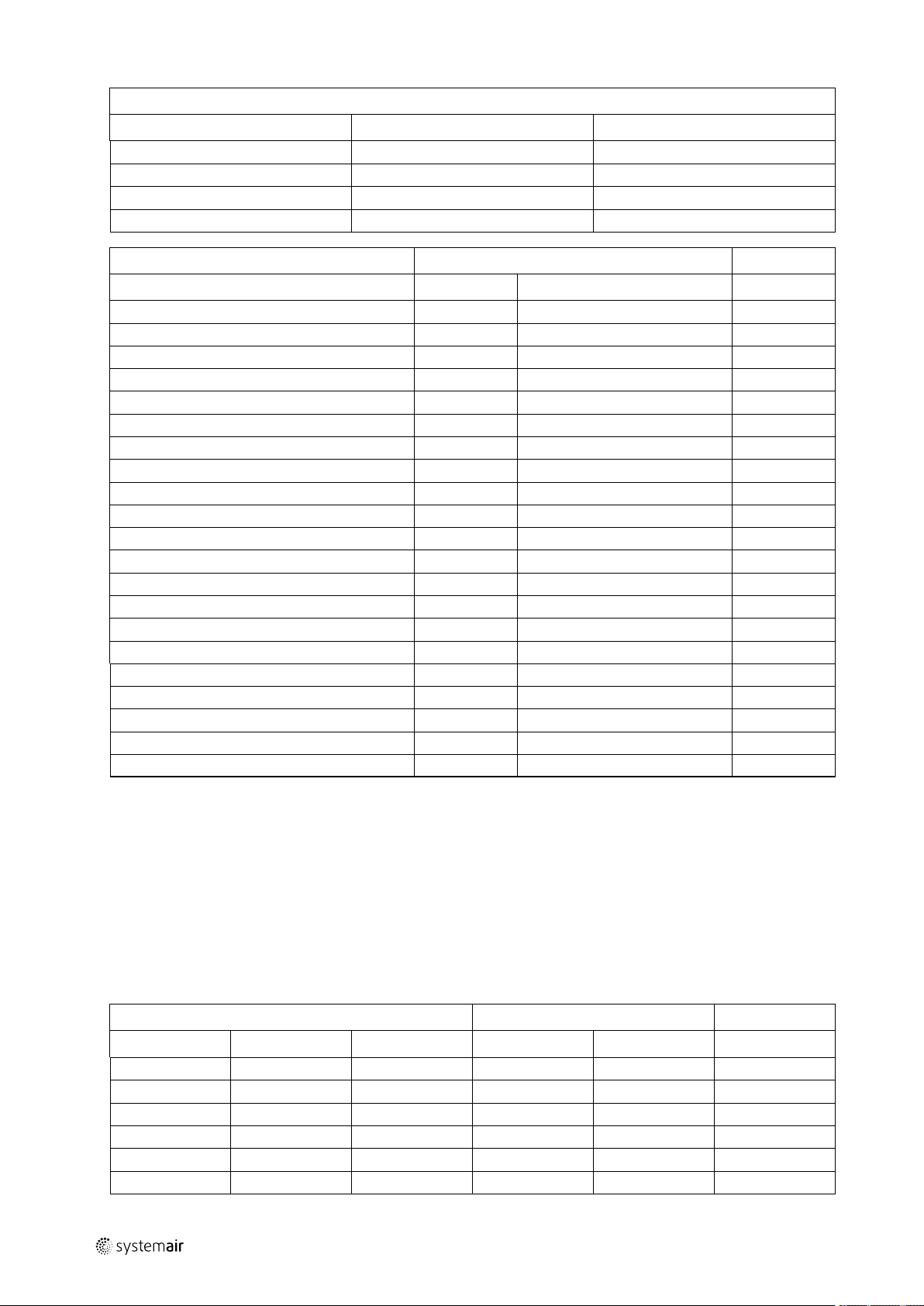
5-2
| Assembly of base frame – height 118 mm for unit sizes 20 – 31
End profile type D (width of base frame)
Unit size Quantity
Geniox24 2 2470
Geniox27 2 2770
Geniox29 2 2970
Geniox31 4 1585
Length [mm]
Adjustable length of frame — L [mm]
482-564 3 400 6
582-664 3 500 6
682-764 3 600 6
782-864 3 700 6
882-964 3 800 6
982-1064 3 900 6
1082-1164 3 1000 6
1182-1264 3 1100 6
1282-1364 3 1200 6
1382-1464 3 1300 6
1482-1564 3 14000 6
1582-1664 3 1500 6
1682-1764 3 1600 6
1782-1864 3 1700 6
1882-1964 3 1800 6
1982-2064 3 1900 6
2082-2164 3 2000 6
2182-2264 3 2100 6
2282-2364 3 2200 6
2382-2464 3 2300 6
2482-2564 3 2400 6
Quantity
Length profile type C
Length of profile [mm]
Corner A
Quantity
5.2 Base frame length 2582 – 4964 [mm] Unit size 20 – 31
End profile type D (width of base frame)
Unit size Quantity
Geniox20 2 2070 2 941 1
Geniox22 2 2270 2 1041 1
Geniox24 2 2470 2 1141 1
Geniox27 2 2770 2 1291 1
Geniox29 2 2970 2 1391 1
Geniox31 4 1585 2 1491 1
Length [mm]
Middle profile type D1
Quantity
Length [mm]
Spacer F
Quantity
output |
Page 79
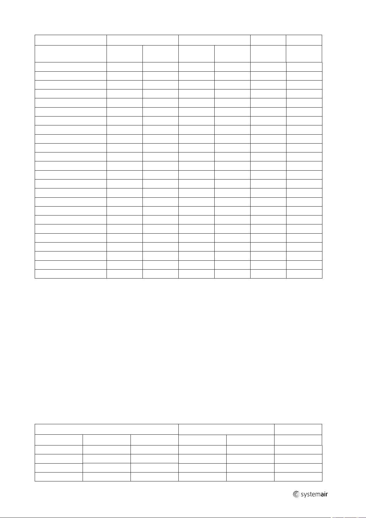
Assembly of base frame – height 118 mm for unit sizes 20 – 31 |
5-3
Length profile type C1 Length profile type C2
Adjustable length of
frame — L [mm]
2582-2664 3 1200 3 1300 6 3
2682-2764 3 1300 3 1300 6 3
2782-2864 3 1300 3 1400 6 3
2882-2964 3 1400 3 1400 6 3
2982-3064 3 1400 3 1500 6 3
3082-3164 3 1500 3 1500 6 3
3182-3264 3 1500 3 1600 6 3
3282-3364 3 1600 3 1600 6 3
3382-3464 3 1600 3 1700 6 3
3482-3564 3 1700 3 1700 6 3
3582-3664 3 1700 3 1800 6 3
3682-3764 3 1800 3 1800 6 3
3782-3864 3 1800 3 1900 6 3
3882-3964 3 1900 3 1900 6 3
3982-4064 3 1900 3 2000 6 3
4082-4164 3 2000 3 2000 6 3
4182-4264 3 2000 3 2100 6 3
4282-4364 3 2100 3 2100 6 3
4382-4464 3 2100 3 2200 6 3
4482-4564 3 2200 3 2200 6 3
4582-4664 3 2200 3 2300 6 3
4682-4764 3 2300 3 2300 6 3
4782-4864 3 2300 3 2400 6 3
4882-4964 3 2400 3 2400 6 3
Quantity
Length
[mm]
Quantity
Length
[mm]
Corner A
Quantity Quantity
Splice B
5.3 Base frame length 4982 – 6164 [mm] Unit size 20 – 31
End profile type D (width of base frame)
Unit size Quantity
Geniox20 2 2070 4 941 2
Geniox22 2 2270 4 1041 2
Geniox24 2 2470 4 1141 2
Geniox27 2 2770 4 1291 2
Length [mm]
Middle profile type D1
Quantity
Length [mm]
Spacer F
Quantity
output |
Page 80

5-4
| Assembly of base frame – height 118 mm for unit sizes 20 – 31
End profile type D (width of base frame)
Unit size Quantity
Geniox29 2 2970 4 1391 2
Geniox31
Length profile type C1 Length profile type C2 Length profile type C3
Adjustable
length of
frame — L
[mm]
4982-5064 3 1600 3 1600 3 1700 6 6
5082-5164 3 1600 3 1700 3 1700 6 6
5182-5264 3 1700 3 1700 3 1700 6 6
5282-5364 3 1700 3 1700 3 1800 6 6
5382-5464 3 1700 3 1800 3 1800 6 6
5482-5564 3 1800 3 1800 3 1800 6 6
5582-5664 3 1800 3 1800 3 1900 6 6
5682-5764 3 1800 3 1900 3 1900 6 6
5782–5864 3 1900 3 1900 3 1900 6 6
5882-5964 3 1900 3 1900 3 2000 6 6
5982-6064 3 1900 3 2000 3 2000 6 6
6082-6164 3 2000 3 2000 3 2000 6 6
Qty
4 1585 4 1491 2
Length [mm]
Length [mm]
Qty
Length [mm]
Middle profile type D1
Quantity
Length [mm]
Qty
Length [mm]
Spacer F
Quantity
A B
Qty Qty
output |
Page 81

Assembly of base frame – height 218 mm for unit sizes 10 – 18 |
Annex 6 Assembly of base frame – height 218 mm for unit sizes 10 – 18
6-1
A = Corner
C = Length profile
D = End profile (width of base frame)
B = Splice
D1 = Middle profile
6.1 Base frame length 482– 2564 [mm] Unit size 10 – 18
output |
End profile type D (width of base frame)
Unit size Quantity
Geniox10 2 1070
Geniox11 2 1170
Length of endprofile (width of base
frame) [mm]
Page 82

6-2
| Assembly of base frame – height 218 mm for unit sizes 10 – 18
End profile type D (width of base frame)
Unit size Quantity
Geniox12 2 1270
Geniox14 2 1470
Geniox16 2 1670
Geniox18 2 1870
Length of endprofile (width of base
frame) [mm]
Length profile type C
Adjustable length of
frame — L [mm]
482 – 564 2 400 4
582 – 664 2 500 4
682 – 764 2 600 4
782 – 864 2 700 4
882 — 964 2 800 4
982 – 1064 2 900 4
1082 — 1164 2 1000 4
1182 – 1264 2 1100 4
1282 – 1364 2 1200 4
1382 – 1464 2 1300 4
1482 – 1564 2 1400 4
1582 – 1664 2 1500 4
1682 — 1764 2 1600 4
1782 — 1864 2 1700 4
1882 — 1964 2 1800 4
1982 — 2064 2 1900 4
2082 — 2164 2 2000 4
2182 — 2264 2 2100 4
2282 — 2364 2 2200 4
2382 — 2464 2 2300 4
2482 — 2564 2 2400 4
Quantity
Length of profile [mm]
Corner A
Quantity
6.2 Base frame length 2582 – 4964 [mm] Unit size 10 – 18
End profile type D (width of base frame)
Unit size Quantity
Geniox10 2 1070 1 950
Geniox11 2 1170 1 1050
width of base
frame [mm]
Quantity
Middle profile type D1
Length [mm]
output |
Page 83

Assembly of base frame – height 218 mm for unit sizes 10 – 18 |
6-3
End profile type D (width of base frame)
Unit size Quantity
Geniox12 2 1270 1 1150
Geniox14 2 1470 1 1350
Geniox16 2 1670 1 1550
Geniox18 2 1870 1 1750
Length profile C1 Length profile C2
Adjustable length
of frame — L [mm]
2582-2664 2 1200 2 1300 4 2
2682-2764 2 1300 2 1300 4 2
2782-2864 2 1300 2 1400 4 2
2882-2964 2 1400 2 1400 4 2
2982-3064 2 1400 2 1500 4 2
3082-3164 2 1500 2 1500 4 2
3182-3264 2 1500 2 1600 4 2
3282-3364 2 1600 2 1600 4 2
3382-3464 2 1600 2 1700 4 2
3482-3564 2 1700 2 1700 4 2
3582-3664 2 1700 2 1800 4 2
3682-3764 2 1800 2 1800 4 2
3782-3864 2 1800 2 1900 4 2
3882-3964 2 1900 2 1900 4 2
3982-4064 2 1900 2 2000 4 2
4082-4164 2 2000 2 2000 4 2
4182-4264 2 2000 2 2100 4 2
4282-4364 2 2100 2 2100 4 2
4382-4464 2 2100 2 2200 4 2
4482-4564 2 2200 2 2200 4 2
4582-4664 2 2200 2 2300 4 2
4682-4764 2 2300 2 2300 4 2
4782-4864 2 2300 2 2400 4 2
4882-4964 2 2100 2 2100 4 2
Quantity
Length [mm]
width of base
frame [mm]
Quanti-
ty
Length [mm]
Middle profile type D1
Quantity
Corner A
Quantity Quantity
Length [mm]
Splice B
output |
Page 84
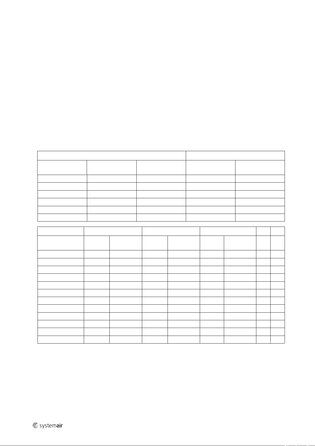
6-4
| Assembly of base frame – height 218 mm for unit sizes 10 – 18
6.3 Base frame length 4982 – 6164 [mm] Unit size 10 – 18
End profile type D (width of base frame)
Unit size Quantity
Geniox10 2 1070 2 950
Geniox11 2 1170 2 1050
Geniox12 2 1270 2 1150
Geniox14 2 1470 2 1350
Geniox16 2 1670 2 1550
Geniox18 2 1870 2 1750
Length profile C1 Length profile C2 Length profile C3
Adjustable length
of frame — L [mm]
4982–5064 2 1600 2 1600 2 1700 4 4
5082-5164 2 1600 2 1700 2 1700 4 4
5182-5264 2 1700 2 1700 2 1700 4 4
5282-5364 2 1700 2 1700 2 1800 4 4
5382-5464 2 1700 2 1800 2 1800 4 4
5482-5564 2 1800 2 1800 2 1800 4 4
5582-5664 2 1800 2 1800 2 1900 4 4
5682-5764 2 1800 2 1900 2 1900 4 4
5782-5864 2 1900 2 1900 2 1900 4 4
5882-5964 2 1900 2 1900 2 2000 4 4
5982-6064 2 1900 2 2000 2 2000 4 4
6082-6164 2 2000 2 2000 2 2000 4 4
Quantity
Length
[mm]
width of base frame
[mm]
Quantity
Length
[mm]
Middle profile type D1
Quantity
Quantity
Length
[mm]
Length [mm]
A B
Qty Qty
output |
Page 85

Assembly of base frame – height 218 mm for unit sizes 20 – 31 |
Annex 7 Assembly of base frame – height 218 mm for unit sizes 20 – 31
7-1
A = Corner
C = Length profile
D = End profile (width of base frame)
B = Splice
F = Spacer
D1 = Middle profile
7.1 Base frame length 482– 2564 [mm] Unit size 20-31
output |
End profile type D (width of base frame)
Unit size Quantity
Geniox20 2 2070
Geniox22 2 2270
Geniox24 2 2470
Geniox27 2 2770
Length [mm]
Page 86

7-2
| Assembly of base frame – height 218 mm for unit sizes 20 – 31
End profile type D (width of base frame)
Unit size Quantity
Geniox29 2 2970
Geniox31
4 1585
Length [mm]
Adjustable length of frame — L [mm]
482-564 3 400 6
582-664 3 500 6
682-764 3 600 6
782-864 3 700 6
882-964 3 800 6
982-1064 3 900 6
1082-1164 3 1000 6
1182-1264 3 1100 6
1282-1364 3 1200 6
1382-1464 3 1300 6
1482-1564 3 14000 6
1582-1664 3 1500 6
1682-1764 3 1600 6
1782-1864 3 1700 6
1882-1964 3 1800 6
1982-2064 3 1900 6
2082-2164 3 2000 6
2182-2264 3 2100 6
2282-2364 3 2200 6
2382-2464 3 2300 6
2482-2564 3 2400 6
Quantity
Length profile type C
Length of profile [mm]
Corner A
Quantity
7.2 Base frame length 2582 – 4964 [mm] Unit size 20 – 31
End profile type D (width of base frame)
Unit size Quantity
Geniox20 2 2070 2 941 1
Geniox22 2 2270 2 1041 1
Geniox24 2 2470 2 1141 1
Geniox27 2 2770 2 1291 1
Geniox29 2 2970 2 1391 1
Geniox31
4 1585 2 1491 1
Length [mm]
Middle profile type D1
Quantity
Length [mm]
Spacer F
Quantity
output |
Page 87

Assembly of base frame – height 218 mm for unit sizes 20 – 31 |
7-3
Length profile type C1 Length profile type C2
Adjustable length of
frame — L [mm]
2582-2664 3 1200 3 1300 6 3
2682-2764 3 1300 3 1300 6 3
2782-2864 3 1300 3 1400 6 3
2882-2964 3 1400 3 1400 6 3
2982-3064 3 1400 3 1500 6 3
3082-3164 3 1500 3 1500 6 3
3182-3264 3 1500 3 1600 6 3
3282-3364 3 1600 3 1600 6 3
3382-3464 3 1600 3 1700 6 3
3482-3564 3 1700 3 1700 6 3
3582-3664 3 1700 3 1800 6 3
3682-3764 3 1800 3 1800 6 3
3782-3864 3 1800 3 1900 6 3
3882-3964 3 1900 3 1900 6 3
3982-4064 3 1900 3 2000 6 3
4082-4164 3 2000 3 2000 6 3
4182-4264 3 2000 3 2100 6 3
4282-4364 3 2100 3 2100 6 3
4382-4464 3 2100 3 2200 6 3
4482-4564 3 2200 3 2200 6 3
4582-4664 3 2200 3 2300 6 3
4682-4764 3 2300 3 2300 6 3
4782-4864 3 2300 3 2400 6 3
4882-4964 3 2400 3 2400 6 3
Quantity
Length
[mm]
Quantity
Length
[mm]
Corner A
Quantity Quantity
Splice B
7.3 Base frame length 4982 – 6164 [mm] Unit size 20 – 31
End profile type D (width of base frame)
Unit size Quantity
Geniox20 2 2070 4 941 2
Geniox22 2 2270 4 1041 2
Geniox24 2 2470 4 1141 2
Geniox27 2 2770 4 1291 2
Length [mm]
Middle profile type D1
Quantity
Length [mm]
Spacer F
Quantity
output |
Page 88

7-4
| Assembly of base frame – height 218 mm for unit sizes 20 – 31
End profile type D (width of base frame)
Unit size Quantity
Geniox29 2 2970 4 1391 2
Geniox31
Length profile type C1 Length profile type C2 Length profile type C3
Adjustable
length of
frame — L
[mm]
4982-5064 3 1600 3 1600 3 1700 6 6
5082-5164 3 1600 3 1700 3 1700 6 6
5182-5264 3 1700 3 1700 3 1700 6 6
5282-5364 3 1700 3 1700 3 1800 6 6
5382-5464 3 1700 3 1800 3 1800 6 6
5482-5564 3 1800 3 1800 3 1800 6 6
5582-5664 3 1800 3 1800 3 1900 6 6
5682-5764 3 1800 3 1900 3 1900 6 6
5782–5864 3 1900 3 1900 3 1900 6 6
5882-5964 3 1900 3 1900 3 2000 6 6
5982-6064 3 1900 3 2000 3 2000 6 6
6082-6164 3 2000 3 2000 3 2000 6 6
Qty
4 1585 4 1491 2
Length [mm]
Length [mm]
Qty
Length [mm]
Middle profile type D1
Quantity
Length [mm]
Qty
Length [mm]
Spacer F
Quantity
A B
Qty Qty
output |
Page 89

Installation of steel roof in the sizes 10 – 31 |
8-1
Annex 8 Installation of steel roof in the sizes 10 – 31
8.1 Overview
• Mount rails A1, B2, C3, D4, E5 on the unit for support of trapezoidal roof plates (mount also rails Y and Z on units of
the size 30 and on units that are larger than size 30 longitudinally at the centre- line of the units).
• Place foam bands – P – on the horizontal rails A1, B2, C3 and D4 for support of roof plates.
• Calculate overhang of the roof at both ends of the unit and mount roof overhang profile – G1 on the first trapezoidal
roof plate – F1 before the roof plate is mounted.
• Place and mount roof plates F1, F2, F3 and so on.
• Remember foam bands on the side laps between roof plates to prevent rainwater from passing through.
• Place roof overhang profile – G5 at the other end of the unit before the last roof plate is mounted.
• Mount sides and corners on the roof.
• Apply sealing where plates are joined to ensure water resistance - even in stormy weather.
8.1.1 Mount rails. Units of size 10, 11, 12, and 14
Squeeze sealant in sufficient quantity between the underside of the rails A1, B2, C3, D4, E5 and the horizontal top side
of the unit before the rails are mounted. This means that the rails are standing on sealant to achieve the tightest
connection between rails and unit to prevent rainwater from passing under the rails and into the unit. Mount the rails
A1 and B2 on the front side (the side with the inspection doors) – use the simple self-drilling screws without the sealing
washer – see the illustration of the screw below.
Note:
Rail B2 fits into the rail A1, and this offers the advantage that the rail B2 can be slid inside the rail A1 to
adjust the length of rail B2 accurately to the length of the unit. In this way it is not necessary to spend time
and effort cutting the rail B2
Mount the lower rails C3 and D4 on the back side of the unit.
Note:
Rail D4 fits into the rail C3, and this offers the advantage that the rail D4 can be slid inside the rail C3 to
adjust the length of rail D4 accurately to the length of the unit. In this way it is not necessary to spend time
and effort on cutting the rail D4.
Mount vertical rail – E5 - with the roof slope at each end of the unit
Caution
It is important to place a screw in each hole – even though the number of holes for screws seems to be
very large, a screw in each hole is necessary as the stress on the roof during stormy weather is extremely
high.
8.1.2 Mount rails. Units of size 16 and units larger than size 16.
On units of size 16 and on units that are larger than size 16, rails A1, B2, C3, D4, E5 must be mounted on the unit for
support of trapezoidal roof plates, but also rails Y and Z must be mounted longitudinally at the centre-line of the units
to hold the trapezoidal roof plates.
Squeeze sealant in sufficient quantity between the underside of the rails A1, B2, C3, D4, E5 and the horizontal top side
of the unit before the rails are mounted. This means that the rails are standing on sealant to achieve the tightest
connection between rails and unit to prevent rainwater from passing under the rails and into the unit. Mount the rails
A1 and B2 on the front side (the side with the inspection doors) – use the simple self drilling screws without the sealing
washer – see the illustration of the screw below.
Note:
Rail B2 fits into the rail A1, and this offers the advantage that the rail B2 can be slid inside the rail A1 to
adjust the length of rail B2 accurately to the length of the unit. In this way it is not necessary to spend time
and effort cutting the rail B2.
Mount the lower rails C3 and D4 on the back side of the unit.
output |
Page 90
8-2
| Installation of steel roof in the sizes 10 – 31
Note:
Rail D4 fits into the rail C3, and this offers the advantage that the rail D4 can be slid inside the rail C3 to
adjust the length of rail D4 accurately to the length of the unit. In this way it is not necessary to spend time
and effort cutting the rail D4.
Mount vertical rail – E5 - with the roof slope at each end of the unit.
Mount the rails Y and Z on the unit with the centre-line of the rails exactly over the centre-line of the unit. It is
longitudinal on the middle of the units to hold the trapezoidal roof plates.
Note:
Rail Z fits over the lower rail Y, and this offers the advantage that the rail Z can be slided on the rail Y to
adjust the length of rail Z accurately to the length of the unit. In this way it is not necessary to spent time
and effort on cutting the rail Z.
Caution
It is important to place a screw in each hole – even though the number of holes for screws seems to be
very large, a screw in each hole is necessary as the stress on the roof during stormy weather is extremely
high.
8.1.3 Roof overhang along the long sides of the unit
The roof plates are longer than the width of the unit to ensure sufficient overhang along the sides of the unit.
The overhang is 100 mm along each side of the smallest unit – size 10.
The overhang is 150 mm along each side of the units – size 11, 12, 14.
The overhang is 175 mm along each side of the biggest units – including size 16.
8.1.4 Calculation of the overhang at the ends of the unit. Mount overhang profile – G1.
The roof must be between 200 and 400 mm longer than the length of the unit to secure a roof overhang between 100
mm and 200 mm at the each of the 2 ends of the unit, and the length of this overhang must be calculated before the
first roof plate is mounted.
The unit is delivered with 2 similar overhang profiles - G1 and G5 - one for each end of the roof. Mount one of the 2
roof overhang profiles – G on a trapezoidal roof plate. Use the self drilling, painted screws with sealing washers - W see the illustration.
Note:
Foam bands - P – are necessary between the overhang profile G1 and the roof plate F1. See the illustration.
Self-drilling, painted screws supplied with sealing washer for the mounting of the trapezoidal plate to the roof
overhang profile.
The total cover width of the trapezoidal roof plates always changes with the pitch of 205 mm between the trapezoidal
ribs, making up a total length of the complete roof of - for example 2100 mm, 2305 mm, 2510 mm and so on. We call
this length of the total roof for RL and we call the total length of the complete unit for AL. The trapezoidal roof must
always be longer than the unit, to obtain a reasonable overhang called – XX - of the roof at both ends.
In the table below you will find 40 different lengths of roofs (always changing with the 205 mm) and the lengths of
units that are ideal for each of the 40 alternative roof lengths.
Measure the total length – AL of the unit – for example 5000 mm between the 4982 and 5182 mm mentioned in the
table below.
output |
Page 91

Installation of steel roof in the sizes 10 – 31 |
8-3
AHU length
AL
1670 – 1870 2100 4568 – 4768 4970 7466 – 7666 7840
1877 – 2077 2305 4775 – 4975 5175 7673 – 7873 8045
2084 – 2284 2510 4982 – 5182 5380 7880 – 8080 8250
2291 – 2491 2715 5189 – 5389 5585 8087 – 8287 8455
2498 – 2698 2920 5396 – 5596 5790 8294 – 8494 8660
2705 – 2905 3125 5603 – 5803 5995 8501 – 8701 8865
2912 – 3112 3330 5810 – 6010 6200 8708 – 8908 9070
3119 – 3319 3535 6017 – 6217 6405 8915 – 9115 9275
3326 – 3526 3740 6224 – 6424 6610 9122 – 9322 9480
3533 – 3733 3945 6431 – 6631 6815 9329 – 9529 9685
3740 – 3940 4150 6638 – 6838 7020 9536 – 9736 9890
3947 – 4147 4355 6845 – 7045 7225 9743 – 9943 10095
4154 – 4354 4560 7052 – 7252 7430
4361 - 4561 4765 7259 - 7459 7635
The mentioned length of roof – RL - for this length of unit is 5380 mm (the delivered trapezoidal plates can be
combined to this length - RL = 5380 mm). 5380 mm minus 5000 mm is 380 mm overhang for both ends, and 380/2
mm = 190 mm is the overhang for each end. Place the trapezoidal roof plate F1 with the roof overhang profile G1 on
rail E with an overhang of 190 mm.
Roof length
RL
AHU length
AL
Roof length
RL
AHU length
AL
Roof length
RL
8.1.5 Foam bands between rails and roof plates – mount roof plates.
Place foam bands P between profiles A1, B2, C3, D4 and roof plates.
The trapezoidal roof plates are mounted with the self-drilling, painted screws supplied with sealing washer.
8.1.6 Foam bands between roof plates
Mount the self-adhesive foam band – O - on the underlapping rib for water resistant and effective sealing due to the
small slope of the roof.
8.1.7 Mount roof plates – some of them are overlapping by 2 ribs
The width of each plate is always 1025 mm and some of the plates have to overlap by 2 ribs to achieve the optimal
total length of the whole roof — see the illustration above.
8.1.8 Mount overhang profile – G5 on the other end of the unit.
When the last trapezoidal plate (in this example F5) has been placed on the unit, the second roof overhang profile G5
must be pushed under the trapezoidal roof plate and mounted with the self-drilling, painted screw with sealing washer.
Mounting must be similar to the mounting of roof overhang profile under the trapezoidal roof plate at the other end of
the unit.
8.1.9 Mount side profiles and corners along the edges of the roof to protect persons
Profiles N and O with the rectangular holes are for the long and lower side of the roof because rain can escape through
the holes. Mount the profiles type N first and the profile O last because the profile O goes over the profile N. Mounted
in this order, the profile O can match the end of the roof and the surplus length of the profile O will just cover part of
the previous profile N. Mount the profiles L and M along the long and higher front side of the roof. Mount the 4
protection corners.
8.1.10 Apply sealing on plate joints to ensure water resistance.
Finish installation of the steel roof by sealing all plate joints with silicone to prevent rainwater from passing into the
unit. See examples below of joints to be sealed.
output |
Page 92
9-1
| Speed control for rotor and assembly of divided rotor
Annex 9 Speed control for rotor and assembly of divided rotor
9.1 Speed control
The cabinet with the speed control system for the rotor is installed behind the inspection door in the rotor section.
The cabinet contains the speed controller with all components, terminal blocks, LED displaying the operation mode, the
dual position DIP switch with 8 sliding levers for programming the rotor motor signal and a button for the activation of
the test mode.
Through the different combinations of the 8 sliding levers of this dual position DIP switch, the correct signal is available
for the 3 different motors used for the 12 sizes of air handling units. The sliding levers are set and the function is
checked at the factory. The positions of the levers appear from the tables below.
9.1.1 Selection of correct signal via the 8DIP switch levers
Position Function
Up Active = ON 1
Down
The factory sets the positions of the 8 DIP switch levers for the maximum of 12 revolutions per minute for standard
temperature exchangers and for sorption-hybrid exchangers. The position of each of the 4 DIP switches to the left is
shown below.
Geniox
10 54 0000 90TYD-S214-M 2.8Nm
11 54 0000
12 54 1000
14 77 0000
16 77 1000
18 77 1000
20 85 0100 120TYD-S214-M 5.5Nm
22 95 0100
24 106 0100
27 118 0100
29 112 1100
31 112 1100
Pulley Position for DIP switches to the left
Deactivated = OFF
Motor
Code
0
The factory sets the positions of the 8 DIP switch levers for the maximum of 20 revolutions per minute for sorption
exchangers. The position of each of the 4 DIP switches to the left is shown below.
Geniox
10 70 1000 90TYD-S214-M
11 77 1000
12 95 1000
14 95 1000
16 118 0100 120TYD-S214-M
18 112 1100
20 118 1100
22 132 1100
24 132 0110
27 160 1010
29 160 0110
31 150 0110
Pulley Position for DIP switches to the left
Motor
output |
Page 93
Speed control for rotor and assembly of divided rotor |
9.1.2 Indication of operation mode via red and green LED as well as test of motor
The LED is in the cover of the cabinet.
LED indication Value
No indication Power off
Green
Green – flashes Ready for operation
Green/redstrobe,slow Magnet on the rotor has activated rotor guard
Green/red strobe, fast
Red Rotor guard has not been activated
Number of red flashes in series Value
1
2
3
4
5
Ordinary operation
Restart sequence active
Output current limit
Over voltage
Under voltage
Failure in the controller
Communication failure
9-2
Restart of rotor:
• Switch off power and switch on power again
or
• Press the test button inside the cabinet
Table 3 Test of motor by checking the resistance in all 3 vindings
Motor sizes
90TYD-S214-M 40Ω
120TYD-S214-M 18Ω
120TYD-S214-L 10Ω
Setting of constant speed:
• Set fourth DIP switch lever in position - ON
Test:
• Set fourth DIP switch lever in position – ON
• Press the test button
Ohm
output |
Page 94

9-3
| Speed control for rotor and assembly of divided rotor
9.1.3 Copy of the label with information about connection of cables
This self-adhesive label is always placed on the cover of the cabinet. The text is always in English.
9.2 Assemble the Systemair casing for Geniox 22, Geniox 24 and Geniox 27
Size
Geniox 22 2170 1640 520
Geniox 24 2320 1790 588
Geniox 27 2520 1940 588
Size Quantity
Geniox 22 4 1014
Geniox 24
Geniox 27
A B C
A1
Length (mm)
4 1164
4 1314
output |
Page 95
Size
Geniox
22
Geniox24
Geniox
27
Speed control for rotor and assembly of divided rotor |
B1 B2 B3 B4
Quantity
1 1012-
1 1012-
1 1012-
# Quan-
2310
2610
2710
tity
- - - -
4 1120-
4 1120-
# Quan-
tity
4 2100-
0400
4 2100-
0410
# Quan-
tity
1 10722310
1 10722610
0200
1 10722710
0210
9-4
#
Size
Geniox 22 2170 520 2240
Geniox 24 2320 588 2540
Geniox 27 2520 588 2840
A C D
9.3 Assemble divided rotor for Geniox 29 and Geniox 31
Size
Geniox 29 2890 2090 558
Geniox 31 3040 2240 558
Size Quantity
Geniox 29
Geniox 31
Size
Geniox 31 2 12100510
B1 B2 B3 B4
Size
Geniox
29
Geniox
31
Quantity
1 1012-
1 1012-
# Quan-
2810
2910
A B C
A1
Length (mm)
4 1464
4 1614
B5
Number
# Quan-
tity
4 1210-
0410
4 1120-
0420
# Quan-
tity
4 2100-
0230
4 2100-
0220
tity
1 10722810
1 10722910
#
#
Size
Geniox 29 2890 558 3140
Geniox 31 3040 558 3440
A C D
9.4 Installation of motor that turns rotor and sensor for rotation
Installation of rotor motor and sensor for control of rotation in Geniox — C module after assembly of divided rotor
output |
Page 96

9-5
By delivery of a Geniox — C module with divided rotor,
the motor is installed before delivery to the customer
The drive belt must be placed around the rotor and the
ideal distance is 9 cm from the 2 sides of the rotor. The
rotors are always 20 cm thick. The distance to the drive
belt from a side of the rotor must be between 9–11 cm.
the 2 sides of the rotor.
Motor is mounted on the motor console plate and 4 shock
absorbers are mounted under the plate with M8 bolts.
Sensor for control of rotation must be installed by the
installer. Distance must be 1-4 mm between sensor and
rotor. Check that the brackets which are used for the
assembly of the rotor segments do not hit the sensor.
Pay attention to the heights of the brackets which are
used for the assembly of the rotor segments. Please turn
the rotor by hand in order to verify that the sensor will
not be hit by the brackets.
| Speed control for rotor and assembly of divided rotor
output |
Page 97

Reversible heat pump unit (in separate cover, if heat pump was delivered)
|
10-1
Annex 10 Reversible heat pump unit (in separate cover, if heat pump was delivered)
10.1 Geniox-HP section (reversible heat pump unit)
The air handling unit section – Geniox-HP – is a separate section in the air handling unit, containing a complete standalone reversible heat pump system (heating and cooling). If the air handling unit was delivered with this section, a
separate manual about the heat pump was enclosed in the separate cover.
output |
Page 98

|
11-1
Menu for internal controller in the heat pump unit (in separate cover, if heat pump was delivered)
Annex 11 Menu for internal controller in the heat pump unit (in separate cover, if heat
pump was delivered)
If the air handling unit was delivered with this section, a separate manual about the heat pump was enclosed in the
separate cover
output |
Page 99

Connection of fan motor and set-up manual for frequency converter |
Annex 12 Connection of fan motor and set-up manual for frequency converter
12.1 Connection of fan motor
Delta connection is shown to the left, and star connection is shown to the right.
12.2 Set-up for Danfoss FC101 for Geniox-units with AC motors
SETUP IS DONE IN FACTORY BEFORE DELIVERY
To reload Systemair factory settings from the control panel:
0-50: LCP Copy: [2]
Systemair factory set-up is based on Danfoss initialization.
14-22: Operation mode: [2] Initialisation (Danfoss Initialisation)
Turn power off and on.
Systemair factory set-up:
0-01: Language selection:
1-03: Torque characteristic: Single fan: [3] Auto-Energy optim.
With twin fan set-up: [1] Variable Torque
12-1
1-20: Motor Power: According to motor plate / order papers
With twin fan set-up total power must be used
1-24: Motor Current: According to motor plate / order papers
With twin fan set-up total current must be used
1-25: Motor Nominal Speed: According to motor plate / order papers
1-42: Motor Cable Length: 3m
1-50: Motor Magnetisation at zero speed.: 0 %
1-52: Min. Speed Normal Magnetisation: 10 Hz
1-73: Flying Start: [0] Disabled
1-90: Motor Thermal Protection: [2] Thermistor trip
3-15: Reference 1 Source: [2] Analog input AI54
1-93: Thermistor Source: [1] Analog input AI53
3-03: Maximum Reference: Max. Hz from order papers
3-16 + 3-17: Reference 2- and 3 Source: [0] No function
3-41 + 342: Ramp 1 up and down: 20 Sec.
4-19: Max. Output Frequency: 90Hz
4-14: Motor Speed High Limit: 90Hz
4-18: Current limit: 100 %
5-12: Terminal 27 Digital input: [0] No operation
5-40.0: Function Relay: [3] Drive ready/remote
5-40.1: Function Relay: [3] Drive ready/remote
6-25: Terminal 54 High Reference: Max. Hz from order papers
14-03: Over modulation: [1] Active
14-20: Reset Mode: [2] Automatic reset x 2
output |
Page 100

12-2
0-50: LCP Copy: [1] All to LCP (Copy of Systemair factory settings to panel)
Connections:
0-10V: terminal 54-55
Start: terminal 12-18
Thermistor: terminal 50-53
Drive ready: terminal 1-2
| Connection of fan motor and set-up manual for frequency converter
12.3 AC-fan operation without thermistor for Danfoss FC101
Systemair factory set-up is based on Danfoss initialization.
14-22: Operation mode: [2] Initialisation (Danfoss Initialisation)
Turn power off and on.
Systemair factory set-up:
0-01: Language selection:
1-03: Torque characteristic: [3] Auto-Energy optim.
1-20: Motor power: According to motor plate
1-24: Motor Current: According to motor plate
1-25: Motor Nominal Speed: According to motor plate
1-29: Automatic motor adaption (AMA): [1] Compl.motor adaption to (Turn power off and on.)
1-42: Motor Cable Length: Order specific
1-50: Motor Magnetisation at zero speed.: 0 %
1-52: Min. Speed Normal Magnetisation: 10 Hz
1-73: Flying start: [0] Deaktivated
5-40.0: Function Relay: [3] Drive ready/remote
14-03: Over modulation: [1] Active
14-20: Reset Mode: [2] Automatic reset x 2
0-50: LCP Copy: [1] All to LCP (Copy of Systemair factory settings to panel)
Connections:
0-10V: terminal 54-55
Start: terminal 12-18
Drive ready: terminal 1-2
Jumper terminal 12-27
12.4 Set-up Danfoss FC101 for Geniox-units with PM motors
SETUP IS DONE IN FACTORY BEFORE DELIVERY
To reload Systemair factory settings from the control panel:
0-50: LCP Copy: [2]
Systemair factory set-up is based on Danfoss initialization.
14-22: Operation mode:[2] Initialisation (Danfoss Initialisation)
Turn power off and on.
Systemair factory set-up:
output |
 Loading...