

Page 1

F-R60K
Fire Damper with Quick Mount Kit
Page 2

2/50 | F-R60K
Table of Contents
Overview .........................................................3
Technical Parameters ..................................................5
Diagrams .........................................................9
Dimensions ........................................................10
Ordering Codes ......................................................12
Installation ........................................................13
Electrical parameters ...................................................35
Operation manual ....................................................48
Page 3

3/50 | F-R60K
Fire Damper with Quick Mount Kit
Description
Fire dampers represent passive fire protection, designed with the help of compartmentalization to prevent the spread
of toxic gases, smoke and fire. The opening and closure of the damper blade can be activated remotely. In case of fire,
when the air in the duct exceeds 72 °C, the thermal fuse melts. Melting of the thermal fuse activates the closure of the
damper blade automatically. Damper blade is then mechanically locked in closed position.
Highlights
• Greatly reduced installation time
• 100 mm body length
• On & out of shaft wall installations
• Easy actuator and unit access
• Casing leakage according to EN 1751, class C
• Blade leakage according to EN 1751, class 3
Fire Resistivity
F-R60K fire dampers are CE certified following the Construction Products Regulation according to EN 15650:2010.
Tested according to EN 1366-2:2015 and classified according to EN 13501-3 + A1:2009. The fire damper together with
its installation form an inseparable part of the fire resistivity rating. F-R60K fire dampers are designed for the
installations listed and described in their Handbook.
• Standard supporting construction in accordance with EN 1366-2:2015: EI60 (ve - ho i↔o)S
• Shaft wall – 2 layer, one side covered plasterboard construction: EI60(ve - i↔o)S
Accessories
Detailed information about accessories is available on design.systemair.com
• FCR: Flexible Duct Connection
• R1-F-R60K: Ringlet for Out Installation
Page 4

4/50 | F-R60K
Design
Material Composition
F-R60K damper has galvanized sheet metal casing. High temperature resistant insulation ring around the casing from
expanded vermiculite board with inorganic binder. The vermiculite boards are not harmful to health and do not contain
any asbestos, glass or mineral fibers. Blades are made from non-asbestos calcium silicate board with polyurethane
foam seals for cold smoke and an intumescent seal, that expands in case of fire. Ethylene-propylene rubber used as
duct seal. The product contains no hazardous substances, except for the solder in the thermal fuse, which contains one
milligram of lead. All materials are processed in accordance with local regulations.
Activation Types
By default, actuator operated fire dampers are supplied with an actuator with micro switches, optionally with a power
and communication unit. A fire damper can be equipped with a spring return actuator can be closed with command
from the building management system, or after the breaching of the thermoelectric fuse. Actuator operated fire
dampers are standardly equipped with a thermoelectric fuse, that activates the closing of the damper after the
reaching or exceeding of the ambient temperature of 72°C. The actuator power circuit is interrupted, and its spring
closes the damper blade within 20 seconds.
• B230T or G230T
Fire damper with an activation mechanism with a Belimo or Gruner spring return actuator (AC 230 V) with electrothermal fuse 72°C and auxiliary switches.
• B24T or G24T
Fire damper with an activation mechanism with a Belimo or Gruner spring return actuator (AC/DC 24 V) with electrothermal fuse 72°C and auxiliary switches.
• BST0 or GST0
Fire damper with an activation mechanism with a Belimo or Gruner spring return actuator (AC/DC 24 V) with an electrothermal fuse 72°C and auxiliary switches, with a Belimo supply and communication unit BKN230-24 or Gruner supply
and communication unit FSC-UFC24-2 (other communication units on demand).
• B24T-W or G24T-W
Fire damper with an activation mechanism with a Belimo or Gruner spring return actuator (AC/DC 24 V) with an electrothermal fuse 72°C and auxiliary switches, with provided cable connectors for the supply and communication unit
(communication unit not part of the mechanism).
• B24T-SR or G24T-SR
Fire damper with an activation mechanism with a Belimo or Gruner spring return actuator (AC/DC 24 V) with electrothermal fuse 72°C and auxiliary switches for Modulated dampers (possibility to open the blade at the desired angle).
Page 5

5/50 | F-R60K
Technical Parameters
Durability Test
10000 cycles, actuator controlled (0 … 90 degrees rotation) – with no change of the required properties
10000 cycles, actuator controlled for modular possibility (45 ... 60 degrees rotation) - with no change of the required
properties
Testing Pressure
Underpressure up to 300 Pa
Safe Position
Closed. (In case of fire the damper closes via a spring in the actuator )
Airflow Direction
Both directions
Allowed Air Velocity
Damper can still operate at max. 12 m/s. Air without any mechanical or chemical contamination
Side with Fire Protection
Depending on installation classification: From both sides (i <-> o)
Repeated Opening
Suitable for daily check procedure in suitable environment
Closing/Opening Time
Actuator operated < 20 s
Indicator Closed/Open
Actuator operated - built-in microswitches
Activation Temperature of the Fire Damper Closing
Actuator operated: 72 °C by means of the spring after current interruption in the electro-thermal fuse
Temperature of Transported Air
Minimum: 0 °C, for all types of mechanism
Maximum: 60 °C for 74 °C and 72 °C thermal fuse (All mechanism types)
Environment Suitability
Protected against weather disruptions, with temperature above 0 °C (3K5 according to EN 60721-3-3)
Inspection Possibility
Inspection of blade and gaskets can be done through electro thermal fuse hole with endoscopic camera. To have the
possibility to access the damper internals a flexible connection or duct with access doors must be connected to the
damper.
Page 6

6/50 | F-R60K
Maintenance
Not required. Dry cleaning if demanded by law in the country in which the dampers are installed.
Revisions
Determined by law in the country in which the fire dampers are installed. Recommended at least every 12 months.
Allowed Pressure
1200 Pa
Declared Blade Tightness (EN 1751)
Class 3 as standard up to 500 Pa
Declared Housing Tightness (EN 1751)
Class C as standard up to 500 Pa
Conformity with EC Directives
2006/42/EC Machinery Directive
2014/35/EU Low Voltage Directive
2014/30/EU Electromagnetic Compatibility Directive
Driving Actuator Types
Belimo BFL, BFN; Gruner 340-…-05, 360-…-12
Transport and Storage
Dry indoor conditions with a temperature range of -20 °C to +50 °C
Page 7
7/50 | F-R60K
P1 P2 P9 P10 P7 P8
P6
P11
P3
P5
P4
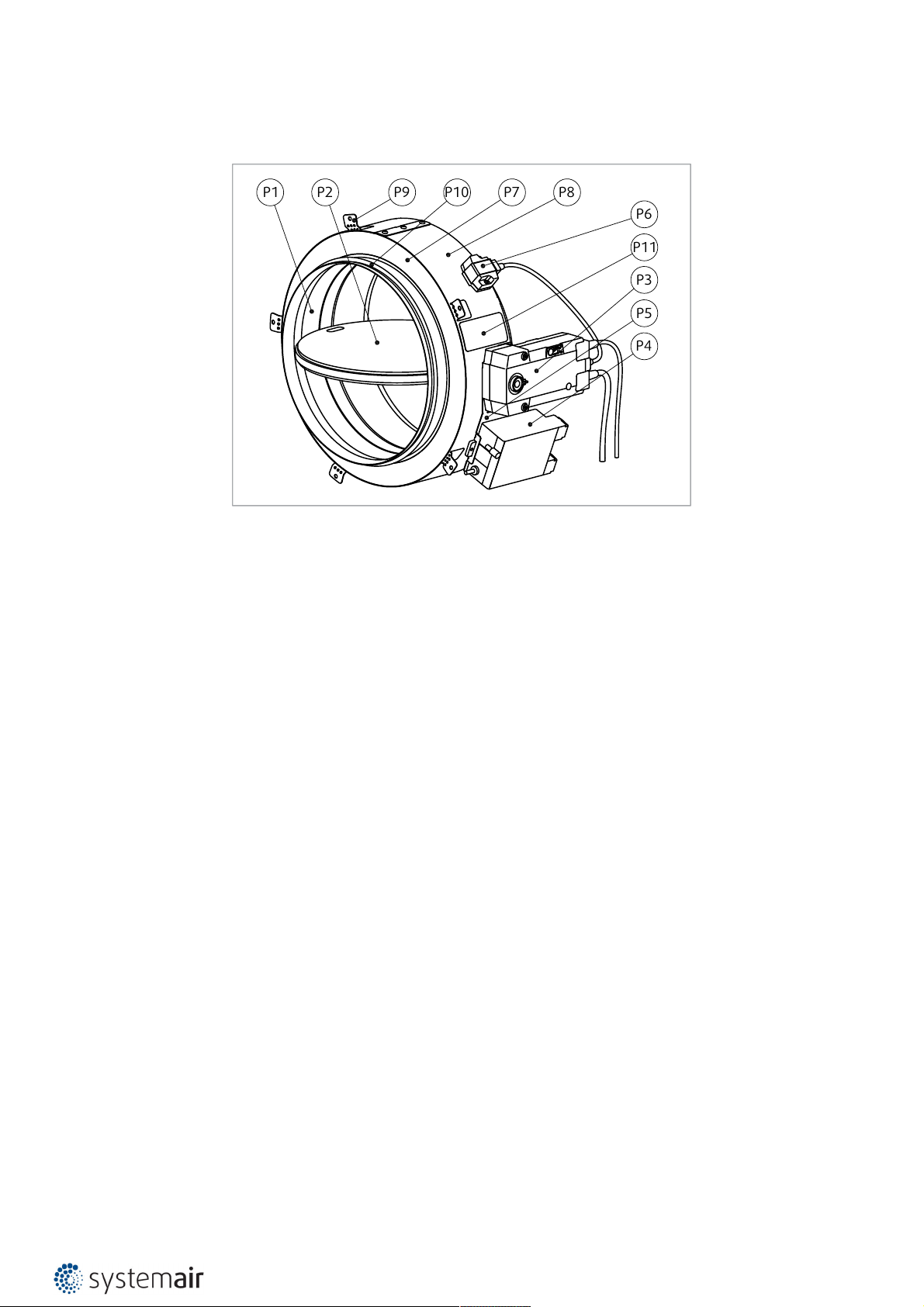
Product Parts
Note:
Depicting only BST0. Other activation types will look differently.
Legend:
P1 - Damper casing
P2 - Damper blade
P3 - Actuator
P4 - Communication unit (only for BST0 and GST0 activation types)
P5 - Holder for communication unit (only for B24T-W and G24T-W activation types)
P6 - Thermal fuse
P7 - High temperature insulating ring
P8 - Sheet metal ring cover
P9 - Bendable hangers
P10 - Duct connection sealings
P11 - Product label
Page 8

8/50 | F-R60K
Assessed Performance
21 CE 1396
Systemair Production a.s.
90043 Kalinkovo 371, Slovakia
21
1396-CPR-0194
EN 15650:2010
Circular fire dampers
F-R60K
Nominal Activation Conditions/Sensitivity
• sensing element load bearing capacity - Pass
• sensing element response temperature - Pass
Closure During Test at Correct Time and in Allowable Time
• closure time and in allowable time - Pass
Operational Reliability
• actuator mechanism = 10 200 cycles: 0° to 90° - Pass 10 000 cycles: 45° to 60° - Pass
Fire Resistance:
Resistivity depending on installation method and situation
• integrity E
• EI60(ve-ho-i↔o)S
• Insulation I
• Smoke leakage S
• Mechanical stability (under E)
• Maintenance of the cross section (under E)
Durability of Response Delay
• sensing element response temperature and load bearing capacity - Pass
Durability of Operational Reliability
• open and closing cycle - Pass
Page 9
9/50 | F-R60K
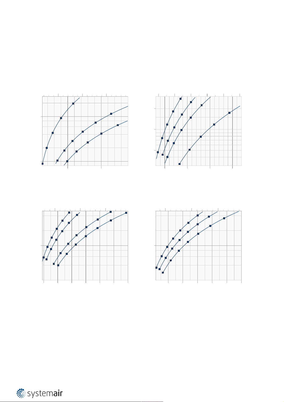
Diagrams
The pressure drop and A-weighted total discharged sound power level depend on the nominal diameter of the damper
and air flow volume at different duct pressures. The type of activation does not influences the airflow parameter,
therefore the activation type is not shown in the diagrams.
F-R60K-...-?
Pressure drop & sound power level (A-weighted)
Pa
50
5
50 100 150 l/s
Size: 100
45 dB(A)
30 dB(A)
25 dB(A)
40 dB(A)
35 dB(A)
30 dB(A)
25 dB(A)
25 dB(A)
250 500 m³/h
35 dB(A)
35 dB(A)
30 dB(A)
45 dB(A)
40 dB(A)
40 dB(A)
F-R60K-...-?
Pressure drop & sound power level (A-weighted)
Pa
500 1000 1500 l/s
Size: 315 Size: 400 Size: 450
Size: 280
50 dB(A)
50 dB(A)
45 dB(A)
45 dB(A)
40 dB(A)
40 dB(A)
35 dB(A)
50 dB(A)
45 dB(A)
5
35 dB(A)
30 dB(A)
30 dB(A)
25 dB(A)
25 dB(A)
45 dB(A)
40 dB(A)
40 dB(A)
35 dB(A)
30 dB(A)
25 dB(A)
25 dB(A)
35 dB(A)
30 dB(A)
50 dB(A)
45 dB(A)
55 dB(A)
50 dB(A)
Size: 125
Size: 140
55 dB(A)
F-R60K-...-?
Pressure drop & sound power level (A-weighted)
100 200 300 400 500 600 l/s
Pa
Size: 160
45 dB(A)
20
10
5
25 dB(A)
40 dB(A)
40 dB(A)
35 dB(A)
35 dB(A)
30 dB(A)
30 dB(A)
35 dB(A)
25 dB(A)
30 dB(A)
25 dB(A)
25 dB(A)
500 1000 1500 2000 m³/h
Size: 180
45 dB(A)
45 dB(A)
40 dB(A)
35 dB(A)
30 dB(A)
Size: 200
45 dB(A)
40 dB(A)
F-R60K-...-?
Pressure drop & sound power level (A-weighted)
1000 2000 3000 l/s
Pa
Size: 500 Size: 560
55 dB(A)
50 dB(A)
50 dB(A)
45 dB(A)
55 dB(A)
5
25 dB(A)
35 dB(A)
30 dB(A)
30 dB(A)
25 dB(A)
25 dB(A)
40 dB(A)
35 dB(A)
35 dB(A)
30 dB(A)
50 dB(A)
45 dB(A)
45 dB(A)
40 dB(A)
40 dB(A)
55 dB(A)
Size: 250
Size: 630
1000 2000 3000 4000 5000 6000 7000m³/h
Legend:
ps (Pa) - Pressure drop
qv (m3^/h), (l/s) - Air flow volume
±Δ (%) - Deviation from measured value
Lwa (dB(A)) - A-weighted total sound power level
v (m/s) - Air face velocity
4000 6000 8000 10000 12000 14000m³/h
Page 10

10/50 | F-R60K
A
V
(m2)
DN (mm)
100 125 140 150 160 180 200 225 250 280 315 355 400 450 500 560 630
0,065
0,069
0,072
0,074
0,076
0,081
0,087
0,094
0,103
0,115
0,130
0,150
0,176
0,208
0,244
0,292
0,356
190
100
(45) (45)
R1
DN+80
DN
≤105 (B230T; B... )
≤120 (G230T; G... )
(mm)
R1 (mm)
DN (mm)
100 125 140 150 160 180 200 225 250 280 315 355 400 450 500 560 630
-48,0
-35,0
-27,5
-22,5
-18,0
-7,5
2,0
15,0
27,0
42,5
60,0
77,0
102,0
127,0
152,0
182,0
217,0
Dimensions & Weights
Free Area
Dimensions
Note:
B... - Belimo activation types
G... - Gruner activation types
Overhangs
Page 11

11/50 | F-R60K
m
(kg)
DN (mm)
100 125 140 150 160 180 200 225 250 280 315 355 400 450 500 560 630
B230T 4,7 4,9 5,3 5,3 5,3 5,7 6,0 6,5 7,0 7,6 8,7 10,1 12,2 14,9 16,5 19,5 22,6
G230T 4,8 5,0 5,4 5,4 5,4 5,8 6,1 6,6 7,1 7,7 8,8 10,2 12,3 15,0 16,6 19,6 22,7
BST0 5,3 5,5 5,9 5,9 5,9 6,3 6,6 7,1 7,6 8,2 9,3 10,7 12,8 15,5 17,1 20,1 23,2
GST0 5,3 5,5 5,9 5,9 5,9 6,3 6,6 7,1 7,6 8,2 9,3 10,7 12,8 15,5 17,1 20,1 23,2
B24T,
B24T-W,
B24T-SR
4,7 4,9 5,3 5,3 5,3 5,7 6,0 6,5 7,0 7,6 8,7 10,1 12,2 14,9 16,5 19,5 22,6
G24T,
G24T-W,
G24T-SR
4,8 5,0 5,4 5,4 5,4 5,8 6,1 6,6 7,1 7,7 8,8 10,2 12,3 15,0 16,6 19,6 22,7
Weights
Page 12
12/50 | F-R60K
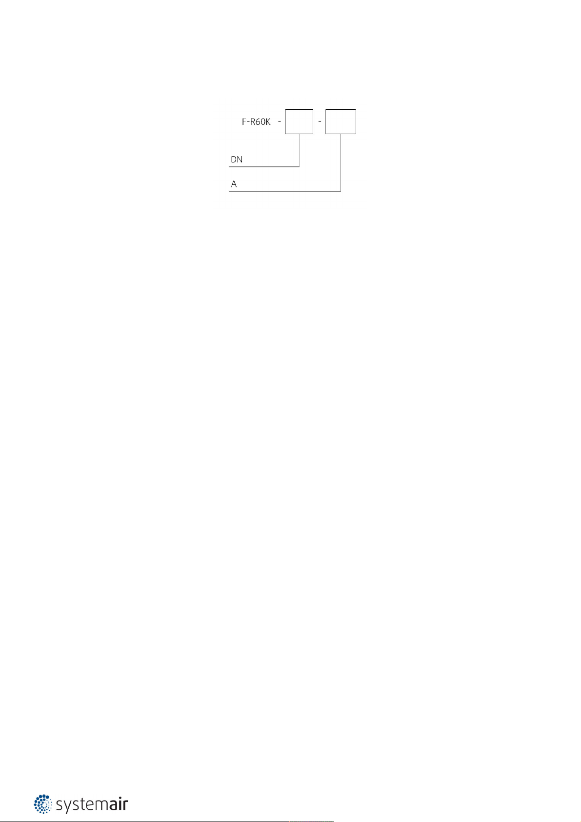
Ordering Code
DN
Dimension, øDN:
100, 125, 140, 150, 160, 180, 200, 225, 250, 280, 315, 355, 400, 450, 500, 560, 630 mm
A - Type of Activation
B230T (230V AC Belimo Actuator)
G230T (230V AC Gruner Actuator)
B24T (24V AC/DC Belimo Actuator)
G24T (24V AC/DC Gruner Actuator)
BST0 (230V AC Supply and communication unit & 24V AC/DC Belimo Actuator)
GST0 (24V AC/DC Supply and communication unit & 24V AC/DC Gruner Actuator)
B24T-W (24V AC/DC Belimo Actuator & Wire connector for communication unit)
G24T-W (24V AC/DC Gruner Actuator & Wire connector for communication unit)
B24T-SR (24V AC/DC Belimo Actuator, modulated 0 V ...10 V)
G24T-SR (24V AC/DC Gruner Actuator, modulated 0 V ...10 V)
Example of the F-R60K Fire Damper Ordering Code
F-R60K-630-B24T-SR
Fire damper with nominal diameter 630 mm, with insulation ring for on and out of the wall EI60S installation. Activated
by thermal fuse and a 24 V Modulated Belimo actuator (0 V ...10 V) that can be used for airflow balancing.
Page 13
13/50 | F-R60K
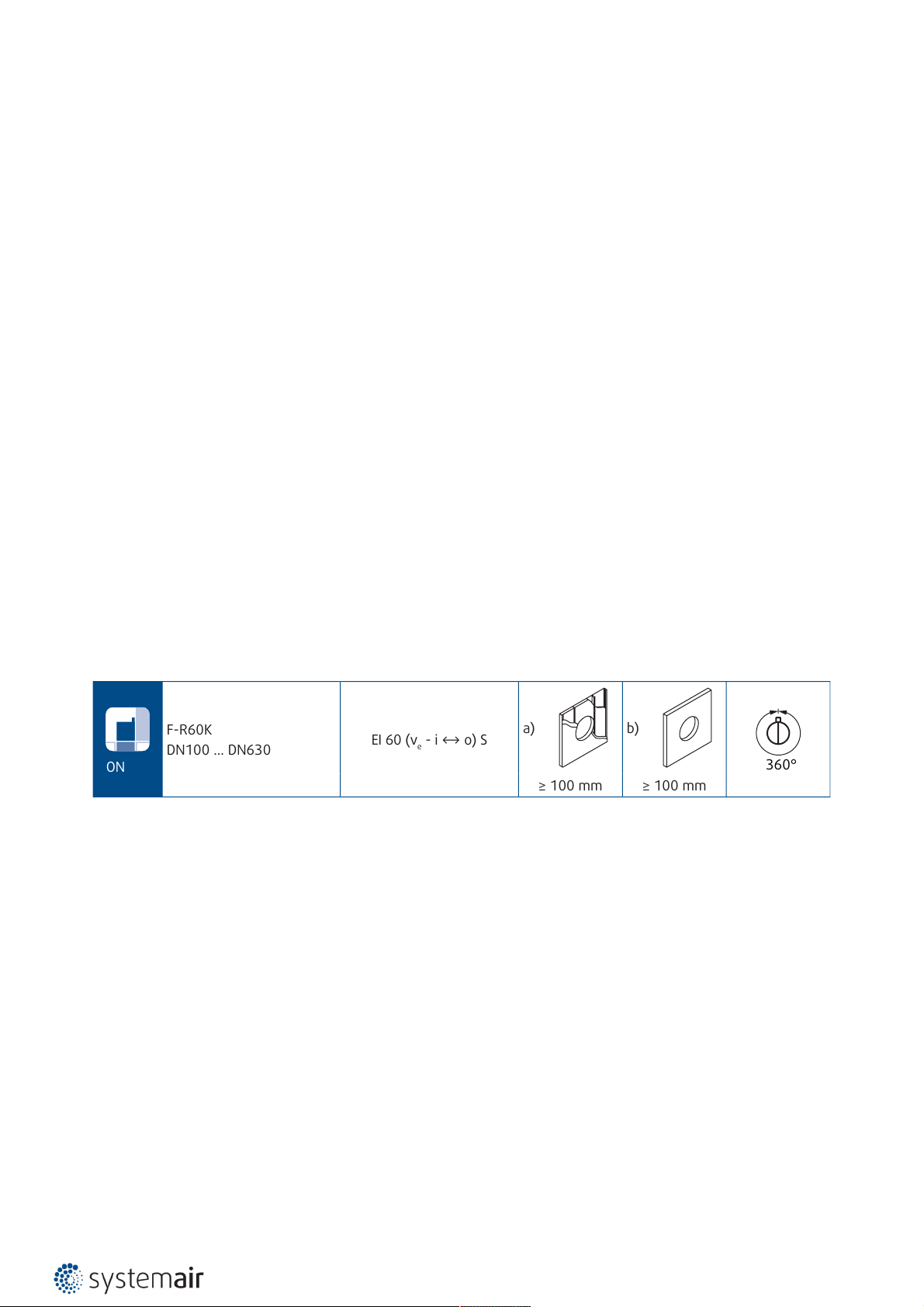
ON
F-R60K
DN100 ... DN630
EI 60 (ve - i ↔ o) S
a) b)
360°
≥ 100 mm ≥ 100 mm
d)
≥ 80 mm
EI 60 (ho - i ↔ o) S
c)
≥ 100 mm
≥ 620 kg/m
3
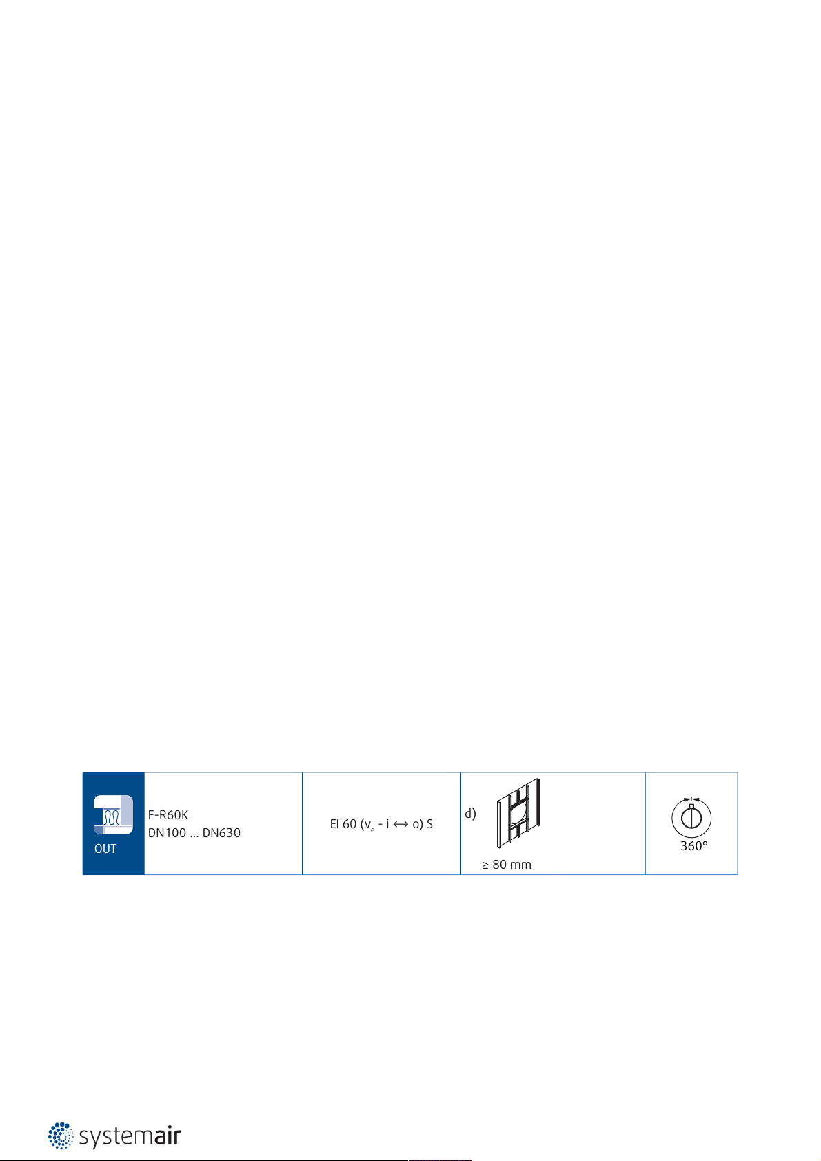
OUT
F-R60K
DN100 ... DN630
EI 60 (ve - i ↔ o) S
a) b)
360°
≥ 100 mm ≥ 100 mm
d)
≥ 80 mm
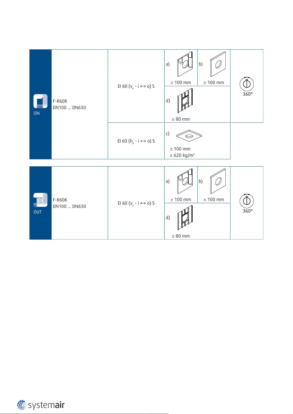
Installation Methods
Notes:
a) - Flexible (plasterboard) wall
b) - Concrete/masonry/cellular concrete (rigid) wall
c) - Concrete/cellular concrete (rigid) floor/ceiling
d) - Shaft wall - one side covered with 2 layers of gypsum board
ve - Vertical wall placement
ho - Horizontal floor/ceiling placement
Installation Rules
• The duct connected to the fire damper must be supported or hung in such a way that the damper does not carry its
weight. The damper must not support any part of the surrounding construction or wall which could cause damage
and consequent damper failure.
• Easy access to mechanism and internal parts during inspection must be considered during damper placement.
• According to the standard EN 1366-2, the distance between the fire damper bodies must be at least 200 mm.
• The distance between the adjacent wall/ceiling and the damper must be at least 75 mm.
• When the damper is installed into a fire partition structure, it must be placed so that the damper blades in its closed
position are located inside this structure.
Page 14

14/50 | F-R60K
• The gap in the installation opening between the damper and the wall/ceiling can be increased by up to 50% of the
gap area or decreased to the smallest amount possible that still provides sufficient space for the installation of the
seal.
• The damper must be earthed after being installed into the duct.
• Lists of all permitted installation methods are provided in Handbook.
Installation, Maintenance & Operation
Some damper parts may have sharp edges – therefore to protect yourself from harm, please use gloves during damper
installation and manipulation. In order to prevent electric shock, fire or any other damage which could result from
incorrect damper usage and operation, it is important to:
1. Ensure that installation is performed by a trained person.
2. Follow the written and depicted instructions provided within Handbook closely.
3. Perform damper inspection in accordance with Handbook.
4. Check the damper’s functionality as per the chapter “Functionality Check” before you install the damper. This
procedure prevents the installation of a damper that has been damaged during transportation or handling.
Information about installation, maintenance and operation is available in the “HandBook_F-R60K” document or more
can be found at design.systemair.com.
Page 15
15/50 | F-R60K
ON
F-R60K
DN100 ... DN630
EI 60 (ve - i ↔ o) S
a) b)
360°
≥ 100 mm ≥ 100 mm
Installation ON a Wall
Standard Flexible & Rigid Wall
IMPORTANT: The insulation ring cannot be delivered separately! The insulation ring is delivered pre-mounted on a
damper.
1. The supporting construction opening must be prepared as depicted in wall preparation. Opening surfaces must be
even and cleaned off.
2. The opening dimension D1 is driven by the nominal dimensions of the damper with added clearance. The flexible
wall opening must be reinforced as per the standards for plasterboard walls when a vertical beam was breached
with the opening.
3. Insert the duct into the opening with its end flush with the supporting construction on the side where the fire
damper will be mounted.
4. Bend outwards hangers on the metal sheet covering ring.
5. Apply a suitable fire resistive caulk (F2) to the fire damper insulation ring on the wall connection side.
6. Insert the damper into the duct and fix the insulation ring through bendable hangers to the wall with screws (F1).
7. If needed, uncover and clean the damper after installation.
8. Check the damper’s functionality
Installation Distances
According to the standard EN 1366-2, the minimum distance from the wall or ceiling to the duct holding the fire
damper is 75 mm. For multiple crossings through a fire resistive wall the minimum distance between the duct opening
is 200 mm. This applies for distances between the duct holding the damper and a nearby foreign object crossing the
fire-resistive wall.
Notes:
a) - Flexible (plasterboard) wall
b) - Concrete/masonry/cellular concrete (rigid) wall
ve - Vertical wall placement
Page 16

16/50 | F-R60K
4
1
3
2
Y
DN
DN+80
≥50
≥12,5
≥100
D1 ≤ (DN+10)
100
Y
1
21 F2 F1
(mm)
DN
≥100
D1 ≤ (DN+10)
100
Y
2
1 F2 F1 2
(mm)
DN+80
Page 17

17/50 | F-R60K
≥
100 mm
≥
100 mm
øD
1
øD
1
≥100 mm
D1
≤
625 mm
C
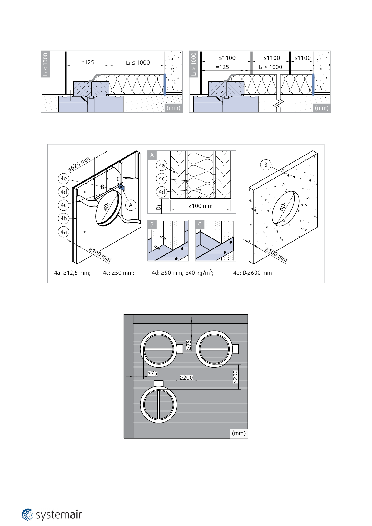
4a: ≥12,5 mm; 4c: ≥50 mm; 4d: ≥50 mm, ≥40 kg/m3; 4e: D1≥600 mm
A
B C
B
4b
4e
4d
4c
4a
A
3
4d
4c
4a
≥75
≥75
≥200
≥200
(mm)
Opening and Wall and/or Ceiling Preparations
Damper Minimum Distances
Page 18

18/50 | F-R60K
Legend for Installation ON a wall
F1 - Screw d=4; e.g. DIN7981
F2 - Fire resistive coating, Kleber K84/Promat or Grena-klebepaste/Grena
1 - Fire damper (F-R60K)
2 - Bendable hanger (part of the sheet metal ring cover)
3 - Concrete/masonry/cellular concrete wall or ceiling
4 - Flexible (plasterboard) wall
4a - 2 layers of plasterboard fireproof plate type F, EN 520
4b - Vertical CW – profiles
4c - Horizontal CW – profiles
4d - Mineral wool; thickness/cubic density see picture.
Page 19

19/50 | F-R60K
ON
F-R60K
DN100 ... DN630
EI 60 (ve - i ↔ o) S
d)
360°
≥ 80 mm
Installation ON a Shaft Wall
One Side Gypsum Covered Wall - 2 Layers
IMPORTANT: The insulation ring cannot be delivered separately! The insulation ring is delivered pre-mounted on a
damper.
1. The supporting construction opening must be prepared as depicted in wall preparation. Opening surfaces must be
even and cleaned off.
2. The opening dimension D1 is driven by the nominal dimensions of the damper with added clearance. The flexible
wall opening must be reinforced as per the standards for plasterboard walls when a vertical beam was breached
with the opening.
Note: Damper installation side is the opposite to the shaft wall beam side.
3. Insert the duct into the opening with its end flush with the supporting construction on the side where the fire
damper will be mounted.
4. Bend outwards hangers on the metal sheet covering ring.
5. Apply a suitable fire resistive caulk (F2) to the fire damper insulation ring on the wall connection side.
6. Insert the damper into the duct and fix the insulation ring through bendable hangers to the wall with screws (F1)
into the wall beams or with plugs for gypsum boards.
7. If needed, uncover and clean the damper after installation.
8. Check the damper’s functionality
Installation Distances
According to the standard EN 1366-2, the minimum distance from the wall or ceiling to the duct holding the fire
damper is 75 mm. For multiple crossings through a fire resistive wall the minimum distance between the duct opening
is 200 mm. This applies for distances between the duct holding the damper and a nearby foreign object crossing the
fire-resistive wall.
Notes:
d) - Shaft wall - one side covered with 2 layers of gypsum board
ve - Vertical wall placement
Page 20

20/50 | F-R60K
4
1
2
Y
DN
100
D1 ≤ (DN+10)
Y
1
1 F2 F1 2
(mm)
DN+80
≥15
≥80
Page 21

21/50 | F-R60K
4a: ≥15 mm; 4c: ≥50 mm
≥80 mm
D1
≥
80 mm
C
B
≤
625 mm
øD
1
A
B C
A
4b
4c
4a
4c
4a
≥75
≥75
≥200
≥200
(mm)
Opening and Wall and/or Ceiling Preparations
Damper Minimum Distances
Page 22

22/50 | F-R60K
Legend for Installation ON a Shaft Wall
F1 - Screw d=4; e.g. DIN7981
F2 - Fire resistive coating, Kleber K84/Promat or Grena-klebepaste/Grena
1 - Fire damper (F-R60K)
2 - Bendable hanger (part of the sheet metal ring cover)
3 Concrete/masonry/cellular concrete wall or ceiling
4 Flexible (plasterboard) wall
4a 2 layers of plasterboard fireproof plate type F, EN 520
4b Vertical CW – profiles
4c Horizontal UW – profiles
Page 23

23/50 | F-R60K
ON
F-R60K
DN100 ... DN630
EI 60 (ho - i ↔ o) S
c)
≥ 100 mm
≥ 620 kg/m
3
Installation ON a Ceiling
Rigid Ceiling, Floor
IMPORTANT: The insulation ring cannot be delivered separately! The insulation ring is delivered pre-mounted on a
damper.
1. The supporting construction opening must be prepared as depicted in wall preparation. Opening surfaces must be
even and cleaned off.
2. The opening dimension D1 is driven by the nominal dimensions of the damper with added clearance.
3. Insert the duct into the opening with its end flush with the supporting construction on the side where the fire
damper will be mounted.
4. Apply glue (F4) to segments of mineral wool (F3). Fill the opening with segments of mineral wool (F3) with density
at least 100 kg/m^3 to create filling between duct and wall.
5. Bend outwards hangers on the metal sheet covering ring.
6. Apply a suitable fire resistive caulk (F2) to the fire damper insulation ring on the wall connection side.
7. Insert the damper into the duct and fix the insulation ring through bendable hangers to the wall with screws (F1)
into the wall beams or with plugs for gypsum boards.
8. If needed, uncover and clean the damper after installation.
9. Check the damper’s functionality
Installation Distances
According to the standard EN 1366-2, the minimum distance from the wall or ceiling to the duct holding the fire
damper is 75 mm. For multiple crossings through a fire resistive wall the minimum distance between the duct opening
is 200 mm. This applies for distances between the duct holding the damper and a nearby foreign object crossing the
fire-resistive wall.
Notes:
c) - Concrete/cellular concrete (rigid) floor/ceiling
d) - Shaft wall - one side covered with 2 layers of gypsum board
ho - Horizontal floor/ceiling placement
Page 24

24/50 | F-R60K
2F3 1 3Y
DN
DN+80
≥100
100
D1 = DN+40
Y
2
1
F1
F2
F4
F3
F10
F11
F12
DN
DN+80
≥100
100
D1 = DN+40
Y
1
1
F1
F10
F11
F12
F2
F4
F3
2
2
(mm) (mm)
Page 25

25/50 | F-R60K
øD
1
≥100 mm
3
≥75
≥75
≥200
≥200
(mm)
Opening and Wall and/or Ceiling Preparations
Damper Minimum Distances
Page 26

26/50 | F-R60K
Legend for Installation ON a Ceiling
F1 - Screw d=4; e.g. DIN7981
F2 - Fire resistive coating, Kleber K84/Promat or Grena-klebepaste/Grena
F3 - Mineral wool filling (min. 100 kg/m^3)
F4 - Fire resistive coating (Hilti CSF-CT).
F10 - L shaped hanger (Hilti MVA-LC).
F11 - Screw M8 with suitable wall plug.
1 - Fire damper (F-R60K)
2 - Bendable hanger (part of the sheet metal ring cover)
3 - Concrete/masonry/cellular concrete wall or ceiling
Page 27

27/50 | F-R60K
OUT
F-R60K
DN100 ... DN630
EI 60 (ve - i ↔ o) S
a) b)
360°
≥ 100 mm ≥ 100 mm
Installation OUT of the Wall
Standard Flexible & Rigid Wall
IMPORTANT: The insulation ring cannot be delivered separately! The insulation ring is delivered pre-mounted on a
damper.
1. The supporting construction opening must be prepared as depicted in wall preparation. Opening surfaces must be
even and cleaned off.
2. The opening dimension D1 is driven by the nominal dimensions of the damper with added clearance. The flexible
wall opening must be reinforced as per the shaft plasterboard walls manufacturer instructions (usually only top and
bottom horizontal metal beam).
3. Place the duct into the opening and onto the load bearing structure (hangers) in such a way that the duct will stick
out of the wall to the needed distance.
4. Press the insulation (F3) for filling the opening around the duct and cut its edges to even it with the wall surface.
5. Fix the duct to a suitable sheet metal ringlet accessory (A1) or UVH30/Lindab ringlet at the wall surface. Then fix
the ringlet through L-profile (F5) to the supporting construction with screws (F1).
6. Insert the damper into the duct and fasten through the duct that crosses the wall with screws (F6). Make sure the
fixing screws are not interfering with the blade movement.
7. Place two threaded rods (F7) through the suitable sheet metal ringlet (accessory) or UVH30 ringlet.
8. Hang the damper weight and connected duct directly after the damper insulating ring also with nuts (F8).
9. Paint the insulation surface in alignment with the wall with a suitable glue (F2) up to 100 mm from the duct to
cover the insulation and part of the wall.
10. Insulate the duct parts between the damper and the wall with one layer of insulation (F8). For easier fixing, the
duct insulation should overlap the dampers’ insulation ring at least 20 mm.
11. Entwine the insulation. Secure the insulation with a binding wire (d=1,6 mm) in the standard way that is applied
when insulating circular ducts or by using wire clamps to sew together the meshes on the top of the insulation (F8).
12. Compress the overlapping insulation while applying aluminium tape (F9) to fix the insulation to the damper ring.
The actuator and thermal sensor must remain uninsulated and without tape for future maintenance.
13. If needed, uncover and clean the damper after installation.
14. Make sure the fixing screws are not interfering with the blade movement and check the damper’s functionality.
Installation Distances
For installation Out of the wall, the minimum distance from the wall or ceiling to the damper body is 100 mm. For
multiple crossings through a fire resistive wall the minimum distance between the duct opening is 200 mm. This
applies for distances between the duct holding the damper and a nearby foreign object crossing the fire-resistive wall.
Notes:
a) - Flexible (plasterboard) wall
b) - Concrete/masonry/cellular concrete (rigid) wall
ve - Vertical wall placement
Page 28

28/50 | F-R60K
3
A1
F5
F8
2
4
1
F7
F9
L
E
Y
DN
≥50
≥12,5
≥100
D1 ≤ (DN+10)
≥20
100
Y
1
F7 F9 F8 F6 1 A1 F1 F5 F2
(mm)
DN+80
DN
≥20
100
≥100
D1 ≤ (DN+10)
Y
2
F7 F9 F8 F6 1 A1 F1 F5 F2
(mm)
DN+80
Page 29
29/50 | F-R60K
LE ≤ 1000
≈125
LE ≤ 1000
LE > 1000≈125
≤1100
LE > 1000
(mm) (mm)
≤1100 ≤1100
≥
100 mm
≥
100 mm
øD
1
øD
1
≥100 mm
D1
≤
625 mm
C
4a: ≥12,5 mm; 4c: ≥50 mm; 4d: ≥50 mm, ≥40 kg/m3; 4e: D1≥600 mm
A
B C
B
4b
4e
4d
4c
4a
A
3
4d
4c
4a
≥75
≥75
≥200
≥200
(mm)
Duct Hanger Rules
Opening and Wall and/or Ceiling Preparations
Damper Minimum Distances
Page 30

30/50 | F-R60K
Legend for Installation OUT of the Standard Wall
F1 - Screw d=4; e.g. DIN7981
F2 - Fire resistive coating, Kleber K84/Promat or Grena-klebepaste/Grena
F3 - Mineral wool filling (min. 100 kg/m^3)
F4 - Fire resistive coating (Hilti CSF-CT)
F5 - L-profile 25x25x3 or part of accessory R1-F-R60K ringlet
F6 - Self taping screws d=4.2
F7 - M10 Steel threaded rod + M10 nuts (2x on each rod)
F8
- Stone wool PAROC Pro Wired Mat 80 AL1 (PAROC), thickness 70 mm, nominal density 80 kg/m^3; Binding wires or
wire clamps.
F9 - Aluminium tape
1 - Fire damper (F-R60K)
2 - Bendable hanger
A1 - Ringlet UVH30 (Lindab) or Accessory: R1-F-R60K ringlet for Out installation.
3 - Concrete/masonry/cellular concrete wall or ceiling.
4 - Flexible (plasterboard) wall
4a - 2 layers of plasterboard fireproof plate type F, EN 520
4b - Vertical CW – profiles
4c - Horizontal UW – profiles
4d - Mineral wool; thickness/cubic density see picture.
Page 31
31/50 | F-R60K
OUT
F-R60K
DN100 ... DN630
EI 60 (ve - i ↔ o) S
d)
360°
≥ 80 mm
Installation OUT of the Shaft Wall
One Side Gypsum Covered Wall - 2 Layers
1. The supporting construction opening must be prepared as depicted in wall preparation. Opening surfaces must be
even and cleaned off.
2. The opening dimension D1 is driven by the nominal dimensions of the damper with added clearance. The flexible
wall opening must be reinforced as per the shaft plasterboard walls manufacturer instructions (usually only top and
bottom horizontal metal beam).
3. Place the duct into the opening and onto the load bearing structure (hangers) in such a way that the duct will stick
out of the wall to the needed distance.
4. Press the insulation (F3) for filling the opening around the duct and cut its edges to even it with the wall surface.
5. Fix the duct to a suitable sheet metal ringlet accessory (A1) or UVH30/Lindab ringlet at the wall surface. Then fix
the ringlet through L-profile (F5) to the supporting construction with screws (F1).
6. Insert the damper into the duct and fasten through the duct that crosses the wall with screws (F6). Make sure the
fixing screws are not interfering with the blade movement.
7. Place two threaded rods (F7) through the suitable sheet metal ringlet (accessory) or UVH30 ringlet.
8. Hang the damper weight and connected duct directly after the damper insulating ring also with nuts (F8).
9. Paint the insulation surface in alignment with the wall with a suitable glue (F2) up to 100 mm from the duct to
cover the insulation and part of the wall.
10. Insulate the duct parts between the damper and the wall with one layer of insulation (F8). For easier fixing, the
duct insulation should overlap the dampers’ insulation ring at least 20 mm.
11. Entwine the insulation. Secure the insulation with a binding wire (d=1,6 mm) in the standard way that is applied
when insulating circular ducts or by using wire clamps to sew together the meshes on the top of the insulation (F8).
12. Compress the overlapping insulation while applying aluminium tape (F9) to fix the insulation to the damper ring.
The actuator and thermal sensor must remain uninsulated and without tape for future maintenance.
13. If needed, uncover and clean the damper after installation.
14. Make sure the fixing screws are not interfering with the blade movement and check the damper’s functionality.
Installation Distances
For installation Out of the wall, the minimum distance from the wall or ceiling to the damper body is 100 mm. For
multiple crossings through a fire resistive wall the minimum distance between the duct opening is 200 mm. This
applies for distances between the duct holding the damper and a nearby foreign object crossing the fire-resistive wall.
Notes:
d) - Shaft wall - one side covered with 2 layers of gypsum board
ve - Vertical wall placement
Page 32

32/50 | F-R60K
A1
F5
F8
2
4
1
F7
F9
L
E
Y
DN
≥20
100
≥15
≥80
D1 ≤ (DN+10)
Y
1
F7 F9 F8 F6 1 A1 F1 F5 F2
(mm)
DN+80
Page 33

33/50 | F-R60K
LE ≤ 1000
≈125
LE ≤ 1000
LE > 1000≈125
≤1100
LE > 1000
(mm) (mm)
≤1100 ≤1100
4a: ≥15 mm; 4c: ≥50 mm
≥80 mm
D1
≥
80 mm
C
B
≤
625 mm
øD
1
A
B C
A
4b
4c
4a
4c
4a
≥75
≥75
≥200
≥200
(mm)
Duct Hanger Rules
Opening and Wall and/or Ceiling Preparations
Damper Minimum Distances
Page 34

34/50 | F-R60K
Legend for Installation OUT of the Shaft Wall
F1 - Screw d=4; e.g. DIN7981
F2 - Fire resistive coating, Kleber K84/Promat or Grena-klebepaste/Grena
F3 - Mineral wool filling (min. 100 kg/m^3)
F4 - Fire resistive coating (Hilti CSF-CT)
F5 - L-profile 25x25x3 or part of accessory R1-F-R60K ringlet
F6 - Self taping screws d=4.2
F7 - M10 Steel threaded rod + M10 nuts (2x on each rod)
F8
- Stone wool PAROC Pro Wired Mat 80 AL1 (PAROC), thickness 70 mm, nominal density 80 kg/m^3; Binding wires or
wire clamps.
F9 - Aluminium tape
1 - Fire damper (F-R60K)
2 - Bendable hanger
A1 - Ringlet UVH30 (Lindab) or Accessory: R1-F-R60K ringlet for Out installation.
4 - Flexible (plasterboard) wall
4a - 2 layers of plasterboard fireproof plate type F, EN 520
4b - Vertical CW – profiles
4c - Horizontal UW – profiles
Page 35

35/50 | F-R60K
A
DN (mm)
100 125 140 150 160 180 200 225 250 280 315 355 400 450 500 560 630
Belimo BFL…-T-... / Gruner 340TA-…-05 Belimo BFN…-T-... / Gruner 360TA-…-12
AT A T
(Nm)
NV
(V)
F
(Hz)
CO CR
WS
(VA)
WN
(W)
B230T
BFL230-T 4 AC 230
50/60
3,5 1,1 6,5 Imax 4 A @ 5 ms
BFN230-T 9 AC 230 9 2,1 10 Imax 4 A @ 5 ms
G230T
340TA-230-…-05-… 5 AC 230 5,5 2 9,5 -
360TA-230-…-12-… 12 AC 230 5,5 1,5 11,5 -
BST0
BFL24-T-ST & BKN230-24 4 AC 230 10 3,5 11 Imax 4 A @ 5 ms
BFN24-T-ST & BKN230-24 9 AC 230 10 3,5 11 Imax 4 A @ 5 ms
GST0
340TA-24-…-05-.../ST01
& FSC-UFC24-2
5 AC/DC 24 8,5 4 11 -
360TA-24…-12-.../ST01
& FSC-UFC24-2
12 AC/DC 24 7 4 9 -
B24T,
B24T-W
BFL24-T, BFL24-T-ST 4 AC/DC 24 2,5 0,8 4 Imax 8,3 A @ 5 ms
BFN24-T, BFN24-T-ST 9 AC/DC 24 4 1,4 6 Imax 8,3 A @ 5 ms
G24T,
G24T-W
340TA-24-…-05-...
340TA-24-…-05-.../ST01
5 AC/DC 24 6,5 2 9 -
360TA-24-…-12-...
360TA-24-…-12-.../ST01
12 AC/DC 24 5 2 7 -
B24T-SR
BFL24-SR-T 4 AC/DC 24 3 1 6,5 Imax 8,3 A @ 5 ms
BFN24-SR-T 9 AC/DC 24 4,5 1,7 8,5 Imax 8,3 A @ 5 ms
G24T-SR
340CTA-24-…-05-… 5 AC/DC 24 6,5 2 7,5
DC (0)2 V ...10 V
/ Ri > (100 kΩ)
50 kΩ (0)4 ... 20 mA
360CTA-24-…-12-… 12 AC/DC 24 5 2 7
Electrical Connections
IMPORTANT
• Danger of electric shock!
• Switch off the power supply before working on any electrical equipment.
• Only qualified electricians are allowed to work on the electrical system.
Actuator Size Map
Electrical Parameters per Activation and Actuator Type
Notes
AT - Activation type
A - Belimo Actuator type
T - Torque
NV - Nominal Voltage
F - Frequency
CO - Consumption in Operation
CR - Consumption in Rest
WS - Wire sizing consumption
Page 36

36/50 | F-R60K
WS - Wire sizing consumption Note
Page 37

37/50 | F-R60K
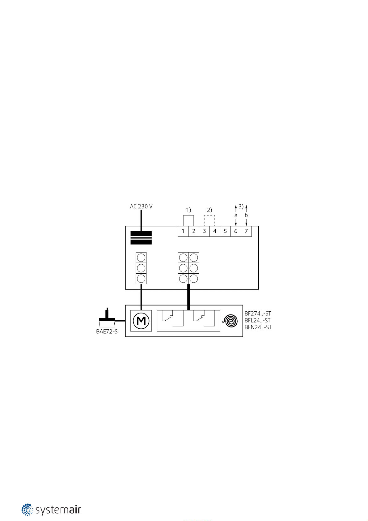
Type of Activation B230T
IMPORTANT: Risk of electric shock!
Switch off the power supply before working on any electrical equipment.
Only qualified electricians are allowed to work on the electrical system.
Actuator power supply: 230V AC, 50/60 Hz
Notes:
• A device that disconnects the pole conductors (minimum contact gap 3 mm) is required for isolation from the power
supply.
• Parallel connection of several actuators possible.
• Power consumption must be observed!
Legend
1 - Blue cable colour
2 - Brown cable colour
S1 - Violet cable colour
S2 - Red cable colour
S3 - White cable colour
S4 - Orange cable colour
S5 - Pink cable colour
S6 - Grey cable colour
Tf - Thermal fuse
Page 38

38/50 | F-R60K
Type of Activation G230T
IMPORTANT: Risk of electric shock!
Switch off the power supply before working on any electrical equipment.
Only qualified electricians are allowed to work on the electrical system.
Actuator power supply: 230V AC, 50/60 Hz
Notes:
• A device that disconnects the pole conductors (minimum contact gap 3 mm) is required for isolation from the power
supply.
• Parallel connection of several actuators possible.
• Power consumption must be observed!
Legend
1 - Blue cable colour
2 - Brown cable colour
S1 - Violet cable colour
S2 - Red cable colour
S3 - White cable colour
S4 - Orange cable colour
S5 - Pink cable colour
S6 - Grey cable colour
Tf - Thermal fuse
Page 39
39/50 | F-R60K
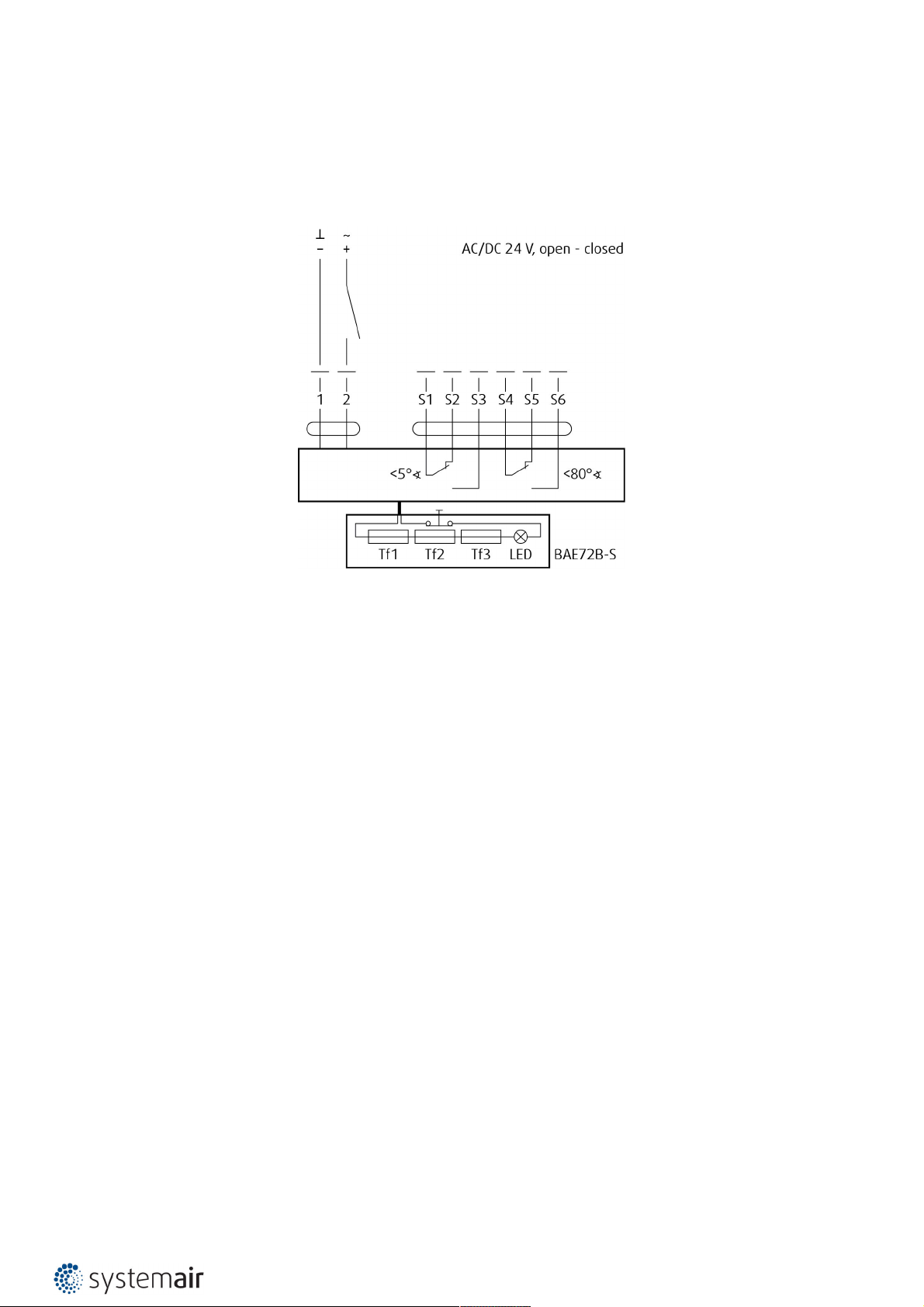
Type of Activation B24T
IMPORTANT: Risk of electric shock!
Switch off the power supply before working on any electrical equipment.
Only qualified electricians are allowed to work on the electrical system.
Actuator power supply: AC (50/60 Hz)/DC 24 V
Legend
1 - Blue cable colour (black for BF24-T)
2 - Red cable colour (white for BF24-T)
S1 - Violet cable colour (white for BF24-T)
S2 - Red cable colour (white for BF24-T)
S3 - White cable colour (white for BF24-T)
S4 - Orange cable colour (white for BF24-T)
S5 - Pink cable colour (white for BF24-T)
S6 - Grey cable colour (white for BF24-T)
Tf - Thermal fuse
Page 40

40/50 | F-R60K
Type of Activation G24T
IMPORTANT: Risk of electric shock!
Switch off the power supply before working on any electrical equipment.
Only qualified electricians are allowed to work on the electrical system.
Actuator power supply: AC (50/60 Hz)/DC 24 V
Notes:
• Supply via safety isolation transformer.
• Parallel connection of several actuators possible.
• Power consumption must be observed!
Legend
1 - Black cable colour
2 - Red cable colour
S1 - Violet cable colour
S2 - Red cable colour
S3 - White cable colour
S4 - Orange cable colour
S5 - Pink cable colour
S6 - Grey cable colour
Tf - Thermal fuse
Page 41
41/50 | F-R60K
Type of Activation BST0
• The actuator and the control module are factory wired.
• Connect the supply voltage to the connecting cable (approx. 1 m, with ferrules).
• Switch off the power supply before working on any electrical equipment.
• Only qualified electricians are allowed to work on the electrical system.
• This type of activation is with a Belimo supply and communication unit BKN230-24 (other communication units on
demand).
• Actuator power supply: AC (50/60 Hz)/DC 24 V
Two LEDs in the Device Indicate the Function Status
LED / Status / Function
Yellow / Flashing / Damper moves OPEN
Yellow / On / Damper OPEN
Green / Flashing / Damper moves CLOSED
Green / On / Damper CLOSED
Yellow and Green / Flashing at double frequency / Fault
Yellow and Green / Off / Power failure
Notes:
• Caution! Main power supply voltage!
• Parallel connection of several actuators possible.
• Power consumption and switching thresholds must be observed!
• Combination of power supply voltage and safety extra-low voltage not permitted at the both auxiliary switches.
Legend
1) - Jumper factory-fitted. Can be removed if necessary to be replaced by a thermoelectric trip
(the safety function will be triggered if terminals 1 and 2 are not linked).
2) - Jumper only used for commissioning purposes and without BKS24-..!
3) - 2-wire conductor to BKS24-...
Page 42
42/50 | F-R60K
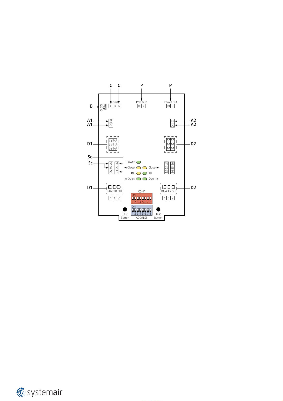
Type of Activation GST0
• The actuator and the control module are factory wired.
• Individual control of 2 fire dampers
• Bus protocols (RS-485): BACnet MS/TP and Modbus RTU
• Automatic baud rate detection with BACnet
• Bus monitoring function
Notes:
• Caution! Main power supply voltage!
• Power consumption and switching thresholds must be observed!
• Combination of power supply voltage and safety extra-low voltage not permitted at the both auxiliary switches.
IMPORTANT:
If only one actuator is connected to the FSC-UFC24-2 the LEDs of the side where no actuator is connected indicate an
alarm. A jumper has to be installed between S4 and S6 in the terminal where there is no actuator connected, to
indicate an “opened” position in the LED. If the second connection is not activated via bus, there will be no alarm signal
on the bus system.
Legend
A1, A2
Analog Application; Digital input for manual override can be selected via bus as „Normally Open“ (= standard open) or
„Normally Closed“ (= standard closed) Default: „Normally Open“
B Position of line termination 120 ohm if FSC-UFC24-2 is last Modbus or BACnet device in line
C RS-485 Coms; Modbus RTU or BACnet MS/TP dip switch selectable
D1, D2 Damper 1, Damper 2; Fire or smoke extraction application
P Main power 24 V AC/DC; Daisy chain from and to other FS-UFC24-2
So Contact open
Page 43

43/50 | F-R60K
Sc Contact closed
Page 44

44/50 | F-R60K
Type of Activation B24T-W
IMPORTANT: Risk of electric shock!
Switch off the power supply before working on any electrical equipment.
Only qualified electricians are allowed to work on the electrical system.
This type of activation is with provided cable connectors for the supply and communication unit (communication unit
not part of the mechanism).
Actuator power supply: AC (50/60 Hz)/DC 24 V
Notes:
• Supply via safety isolation transformer.
• Parallel connection of several actuators possible.
• Power consumption must be observed!
Legend
1 Blue cable colour (black for BF24-T) in connector 1
2 Brown cable colour (white for BF24-T) in connector 1
S1 Violet cable colour (white for BF24-T) in connector 2
S2 Red cable colour (white for BF24-T) in connector 2
S3 White cable colour (white for BF24-T) in connector 2
S4 Orange cable colour (white for BF24-T) in connector 2
S5 Pink cable colour (white for BF24-T) in connector 2
S6 Grey cable colour (white for BF24-T) in connector 2
Tf Thermal fuse
Page 45

45/50 | F-R60K
Type of Activation G24T-W
IMPORTANT: Risk of electric shock!
Switch off the power supply before working on any electrical equipment.
Only qualified electricians are allowed to work on the electrical system.
This type of activation is with provided cable connectors for the supply and communication unit (communication unit
not part of the mechanism).
Notes:
• Supply via safety isolation transformer.
• Parallel connection of several actuators possible.
• Power consumption must be observed!
Legend
1 Black cable colour (black for BF24-T) in connector 1
2 Red cable colour (white for BF24-T) in connector 1
S1 Violet cable colour (white for BF24-T) in connector 2
S2 Red cable colour (white for BF24-T) in connector 2
S3 White cable colour (white for BF24-T) in connector 2
S4 Orange cable colour (white for BF24-T) in connector 2
S5 Pink cable colour (white for BF24-T) in connector 2
S6 Grey cable colour (white for BF24-T) in connector 2
Tf Thermal fuse
Page 46

46/50 | F-R60K
Type of Activation B24T-SR
IMPORTANT: Risk of electric shock!
Switch off the power supply before working on any electrical equipment.
Only qualified electricians are allowed to work on the electrical system.
Actuator power supply: AC (50/60 Hz)/DC 24 V
Notes:
• Supply via safety isolation transformer.
• Power consumption must be observed!
Legend
1 Blue cable colour
2 Brown cable colour
3 White cable colour
5 Orange cable colour
S1 Violet cable colour
S2 Red cable colour
S3 White cable colour
S4 Orange cable colour
S5 Pink cable colour
S6 Grey cable colour
Tf Thermal fuse
Page 47

47/50 | F-R60K
Type of Activation G24T-SR
IMPORTANT: Risk of electric shock!
Switch off the power supply before working on any electrical equipment.
Only qualified electricians are allowed to work on the electrical system.
Actuator power supply: AC (50/60 Hz)/DC 24 V
Notes:
• Supply via safety isolation transformer.
• Power consumption must be observed!
Legend
1 Blue cable colour
2 Brown cable colour
3 Black cable colour
4 Grey cable colour
S1 Violet cable colour
S2 Red cable colour
S3 White cable colour
S4 Orange cable colour
S5 Pink cable colour
S6 Grey cable colour
Tf Thermal fuse
Page 48
48/50 | F-R60K
Test
Test
G230T, G...
Test
B230T, B...
90°
0°
Test
90°
0°
P13
P12
P13
P12
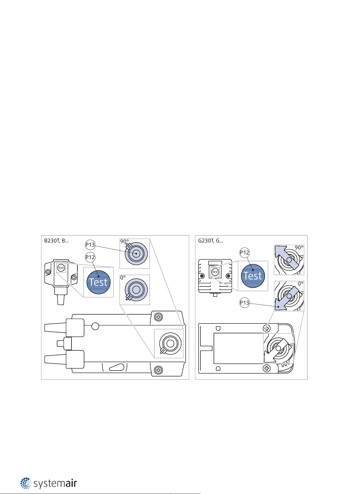
Handling & Manipulation
Handling and manipulation must be done with care. For safety reasons manipulate the damper in its closed possition
and with gloves.
Operation Manual
Warning: Damper blades are spring loaded in the open position and are closing very quick. To avoid injury, make sure
to keep the blade movement area clear while manipulating with the fire damper.
After installation, it is necessary to adjust the damper into its operating position – open the fire damper.
Connect the electric driving mechanism to the relevant electric power supply (see Electrical connection section). The
electromotor is activated and adjusts the damper into its open position.
Functionality Check
• While performing the check, focus on the thermal fuse link’s integrity and a correct position of the damper blades
after their detention in the OPEN and CLOSED positions.
• The fire damper must open automatically after the actuator receives power – the arrow (P13) on the actuator axis in
open possition must point to 90°.
• Press the control switch (P12) on the Thermo electric fuse and hold it until the fire damper is fully closed – the arrow
(P13) on the actuator axis in closed possition must point to 0° - safety possition.
• Release the control switch (P12) on the Thermo electric fuse. The fire damper must become fully open – the arrow
(P13) on the actuator axis in open possition must point to 90° - operating position.
Page 49

49/50 | F-R60K
Damper Inspection
The activation mechanism keeps the dampers on stand-by during their entire life cycle in accordance with this manual
issued by the manufacturer. It is not permitted to alter the dampers in any way nor perform any changes to their
structure without the manufacturer’s consent.
The operator performs regular checks of the dampers as per established regulations and standards at least once every
12 months. The check needs to be performed by an employee who has been specifically trained for this purpose. The
current fire damper condition determined during the inspection needs to be entered into the "Operating Journal" along
with the date of the inspection, the legible name, surname and signature of the employee who performed the
inspection. The Operating Journal includes a copy of the employee’s authorization.
If any discrepancies are discovered, these need to be entered in the Operating Journal along with a proposal for their
removal. The Operating Journal can be found in product "Documents" section on design.systemair.com. Immediately
after the installation and activation of the damper, it needs to be checked under the identical conditions as apply to the
above mentioned 12-month inspections.
The visual check ensures that visible damages on the inspected damper parts are seen. On its external side, the
damper housing and the activation mechanism are checked. Due to the need to perform a visual check of the damper’s
internal parts, open inspection lid connected to the damper or remove the flexible connection connected to the
damper. Visual check can be performed with endoscopic camera through the hole where the thermal fuse is installed.
The damper’s internal casing, thermal fuse, seals, foaming substance, the damper blade condition and accuracy of its
closure during its leaning against the backstop in the closed position must all be checked. There must not be any
strange objects or a layer of impurities from the air distribution systems inside the damper.
NEVER INSPECT THE DAMPERS WHEN THERE IS AIR FLOWING IN THE DUCT SYSTEM!
Recommended Inspection Steps According to the EN 15 650:
1. Damper identification
2. Date of inspection
3. Inspecting electric connection of the activation mechanism (where applicable)
4. Inspecting damper for cleanliness and possible need for cleaning (where needed)
5. Inspecting blade and sealing condition, possible correction and logging (where needed)
6. Inspecting proper fire damper closure
7. Inspecting damper functionality – opening and closing using the control system, physical examination of the
damper’s behavior, possible correction and logging (where needed)
8. Inspecting end switches’ functionality in the open and closed position, possible correction and logging (where
needed)
9. Inspect whether the damper is fulfilling its role as part of the regulation system (where needed)
10. Inspect whether the damper remains in its standard operating position.
11. The damper is usually part of a system. In that case the whole system needs to be checked as described in its
operation and requirements published by the builder of the system.
Supplement
Any deviations from the technical specifications contained in SystemairDESIGN and the terms should be discussed with
the manufacturer. We reserve the right to make any changes to the product without prior notice, provided that these
changes do not affect the quality of the product and the required parameters.
Page 50

Systemair DESIGN • 2021-02-17 • HandBook_F_R60K_en-GB • 2EA87844-C4E6-412A-BCC4-ACF324C0A454
 Loading...