

Page 1
Topvex FR03, FR06, FR08, FR11
Air Handling Unit
Installation instructions
Document in original language | 151625 · A002
GB
Page 2

© Copyright Systemair AB
All rights reserved
E&OE
Systemair AB reserves the rights to alter their products without notice.
This also applies to products already ordered, as long as it does not affect the previously agreed specifications.
151625 | A002
Page 3

1 EU Declaration of Conformity . .. ..... ..... .... .... .... . ...1
2 Warnings. ..... .... .... . .... .... .... . .... .... .... ..... .... .... . .2
3 Product information ... . .... .... .... . .... .... .... . .... .... ...2
3.1 General... .... .... . .... .... .... . ... . .... .... ..... .... ..2
3.2 Technical data .... . ... . .... .... ..... .... .... . .... .... 3
3.2.1 Dimensions... .... .... . .... .... .... . .... ..3
3.2.2 Weights . . .... .... ..... .... .... . ... . .... ...4
3.2.3 Space required. .... .... .... . .... .... .... .5
3.2.4 Electrical data . .... . .... .... ..... .... .... .5
3.3 Transport and storage . ..... .... .... ..... .... .... ..6
4 Installation.. .... ..... .... .... . .... .... .... . .... .... .... ..... ...7
4.1 Unpacking ... . .... .... ..... .... .... . ... . .... .... .... . .7
4.2 Where/how to install .... . ... . .... .... .... . .... .... 7
4.3 Installing the unit. .... .... .... . .... .... ..... .... .... .8
4.4 Supply air sensor... .... .... . .... .... .... . .... .... . 10
4.5 Mounting the sliding door kit. . .... .... .... ..... 10
4.6 Connections .... . ... . .... .... ..... .... .... . .... .... . 13
4.6.1 Ducting ... .... . .... .... .... . .... .... ..... 13
4.6.2 Condensation and heat
insulation .... ..... .... .... . ... . .... .... . 14
4.6.3 Silencers ... . .... .... ..... .... .... . ... . .. 14
4.6.4 Electric connections . . .... .... .... . ...14
4.6.5 Electrical connections,
components. . .... .... .... . .... .... .... . 15
4.6.6 External connections . .... .... .... . ... 16
4.6.7 BMS Connection.. .... .... . .... .... .... 17
4.7 Installing NaviPad control panel .... . .... .... .. 18
4.7.1 Dimensions... .... .... . .... .... .... . .... 18
4.7.2 Mounting control panel. .... . .... .... 19
4.8 Additional equipment . .... . .... .... .... . .... .... . 19
Contents
151625 | A002
Page 4

Page 5
1 EU Declaration of Conformity
Manufacturer
Systemair Sverige AB
Industrivägen 3
SE-739 30 Skinnskatteberg SWEDEN
Office: +46 222 440 00 Fax: +46 222 440 99
www.systemair.com
hereby confirms that the following products:
Air handling units
EU Declaration of Conformity |
1
Topvex FR03 EL Topvex FR03
Topvex FR06 EL Topvex FR06
Topvex FR08 EL Topvex FR08
Topvex FR11 EL Topvex FR11
(The declaration applies only to product in the condition it was delivered in and installed in the facility in accordance with the included
installation instructions. The insurance does not cover components that are added or actions carried out subsequently on the
product)
Topvex FR03 HWL/HWH
Topvex FR06 HWL/HWH
Topvex FR08 HWL/HWH
Topvex FR11 HWL/HWH
Comply with all applicable requirements in the following directives and regulations
Machinery Directive 2006/42/EC Ecodesign Directive 2009/125/EC
Low Voltage Directive 2014/35/EU
EMC Directive 2014/30/EU
The following harmonized standards are applied in applicable parts:
EN ISO 12100:2010
EN 13857
Safety of machinery - General principles for design - Risk assessment and risk reduction
Safety of machinery – Safety distances to prevent hazard zones being reached by upper
327/2011 Requirements for fans
1253/2014 Requirements for ventilation units
or lower limbs
EN 60204-1
EN 60335-1
EN 60335-2-40
Safety of machinery – Electrical equipment of machines – Part 1: General requirements
Household and similar electrical appliances – Safety Part 1: General requirements
Safety of household and similar electrical appliances - Part 2-40: Particular requirements
for electrical heat pumps, air-conditioners and dehumidifiers
EN 50106:2007
Safety of household and similar appliances – Particular rules for routine tests referring to
appliances under the scope of EN 60 335-1 and EN 60967
EN 60529
EN 62233
Degrees of protection provided by enclosures (IP Code)
Measurement methods for electromagnetic fields of household appliances and similar
apparatus with regard to human exposure
EN 61000-6-2
Electromagnetic compatibility (EMC) – Part 6-2: Generic standards – Immunity for
industrial environments
EN 61000-6-3
Electromagnetic compatibility (EMC) – Part 6-3: Generic standards – Emission standards
for residential, commercial and light-industrial environments
The complete technical documentation is available.
Skinnskatteberg, 09-05-2018
Mats Sándor
Technical Director
151625 | A002
Page 6
Warnings
|
2
2 Warnings
The following admonitions will be presented in the different sections of the document:
Danger
• Indicates a potentially or imminently hazardous situation which, if not avoided, could result in death or
serious injury.
Warning
• Indicates a potentially hazardous situation that may result in minor or moderate injuries.
Caution
• Indicates a risk of damaging the product or prevent optimal operation.
Important
• This appliance can be used by children aged from 8 years and above and persons with reduced physical,
sensory or mental capabilities or lack of experience and knowledge if they have been given supervision
or instruction concerning use of the appliance in a safe way and understand the hazards involved.
• Children shall not play with the appliance. Cleaning and user maintenance shall not be made by children
without supervision.
3 Product information
3.1 General
This installation manual concerns air handling unit type Topvex FR manufactured by Systemair Sverige AB. Topvex FR
include the following model options:
• Model: FR03, FR06, FR08, FR11
• Heating coil: EL (Electric), HWL (Water coil, low power), HWH (Water coil, high power) or None.
• Right or left models: R (Right) L (Left). The side where the supply air is located when viewed from the access side.
• Airflow control: CAV – Constant Air Volume, VAV (as accessory) – Variable Air Volume = Constant duct pressure
control
• M0: Aluminium fan impeller
More information regarding VAV control can be found in the VAV kit instruction.
This manual consists of basic information and recommendations concerning the design, installation, start-up and operation, to ensure a proper fail-free operation of the unit.
The key to proper and safe operation of the unit is to read this manual thoroughly, use the unit according to given
guidelines and follow all safety requirements.
151625 | A002
Page 7
3.2 Technical data
M
X
Y
X
G
G
H
H
I
I
L
L/2
L/2
A
B
C
D
J
N
B
N
K
R
C
S
U
øD
Q
P
A
E
E
W W
T
F
1
4
1/2"
M
X
Y
X
G
G
H
H
I
I
L
L/2
L/2
A
D
B
C
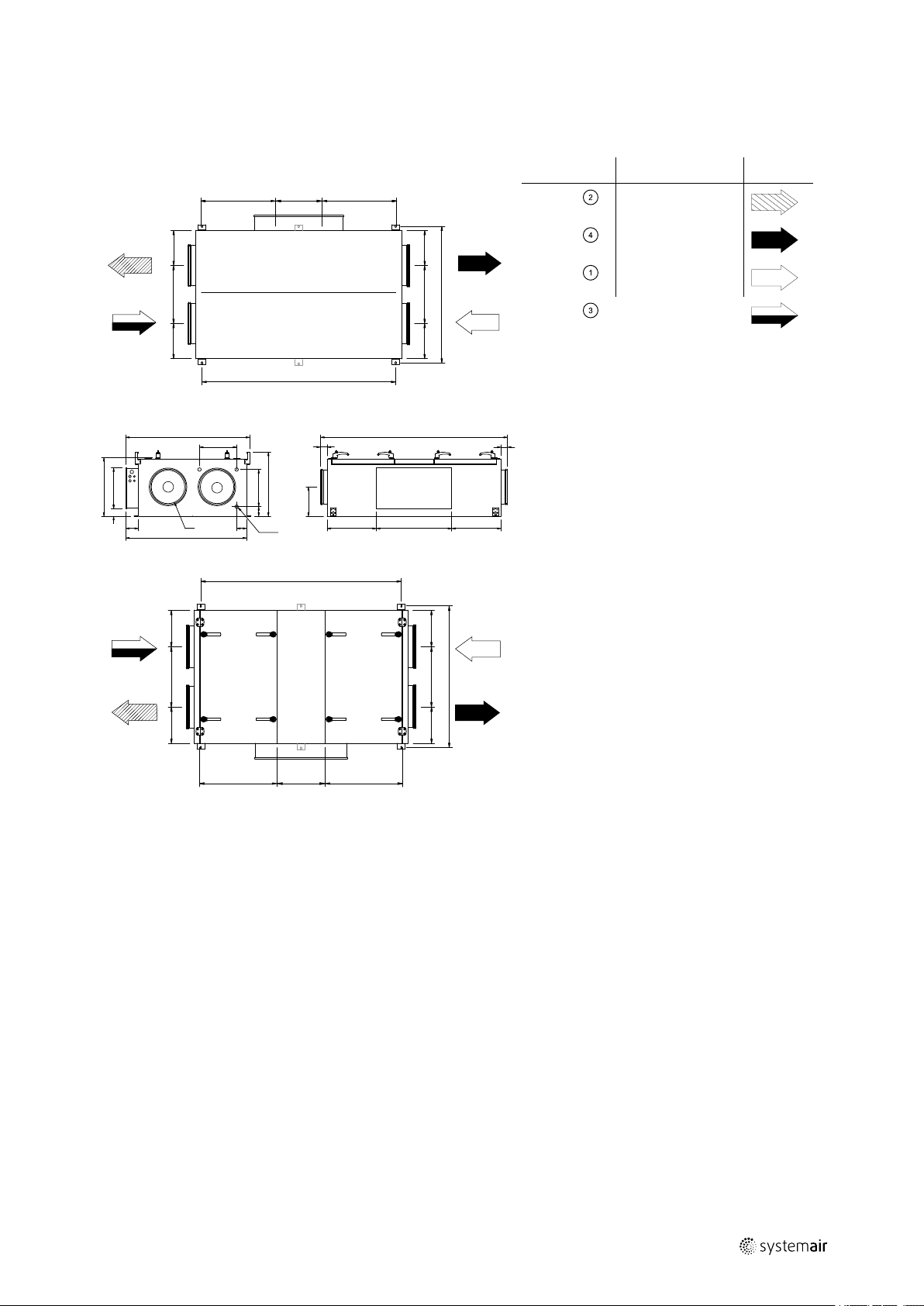
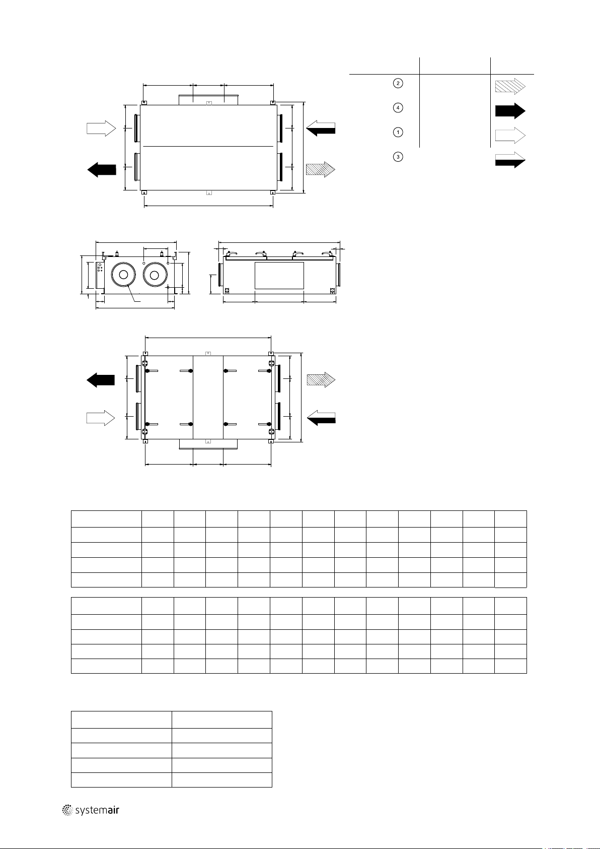
3.2.1 Dimensions
Product information |
3
Bottom side, left hand unit
Left hand unit
Position Description
A
B
C
D
Supply air
Exhaust air
Outdoor air
Extract air
Symbol
Operating side, left hand unit
151625 | A002
Page 8
| Product information
L
X
Y
X
G
H
M
G
H
I
L/2
L/2
A
D
B
C
J
N
B
N
K
R
C
S
U
øD
Q
P
A
E
E
W W
T
F
3
2
L
X
Y
X
G
H
I
M
G
H
I
L/2
L/2
A
D
B
C
4
Bottom side, right hand unit
Right hand unit
Position
A
B
C
D
Description Symbol
Supply air
Exhaust air
Outdoor air
Extract air
Operating side, right hand unit
Table 1 Dimensions
Model
A B C D E F G H I
FR03 1720 1115 540
FR06 2160 1315 640
FR08 2230 1515 740
FR11 2440 1715 840
Model
FR03
L/2
M N P
-
1050 388 64 68 120 375 730 72 456 576 358
ø315
ø400
ø500
ø630
60 270 275 450 275 1145 590 1502
80 275 325 550 325 1345 705 1902
60 355 350 650 400 1545 790 2004
80 405 400 765 432 1745 904 2206
Q
R S T U W X Y
J
K L
FR06 951 1260 414 103 106 102 375 730 158 653 763 384
FR08 1002 1450 514 103 106 120 375 730 275 706 807 384
FR11 1103 1650 614 103 106 120 375 730 329 801 844 520
3.2.2 Weights
Model
FR03 196
FR06 275
FR08 345
FR11 433
Weight (kg)
151625 | A002
Page 9

Product information |
3.2.3 Space required
Fig. 1 Space required
In case the sliding door application is installed the required space corresponds to the height of the sliding door support
bars (50 mm).
5
Model
FR03 576
FR06 763
FR08 807
FR11 844
W (mm)
3.2.4 Electrical data
Table 2 Power Consumption
Fans (W tot.)
Model
FR03 EL 1352 1352 5 3x16 3x25
FR03 (None,
HWL/HWH)
FR03 EL M0 954 954 5 3x16 3x20
FR03 (None,
HWH) M0
FR06 EL 1882 1882 10 3x20 3x35
FR06 (None,
HWL/HWH)
FR08 EL 1944 1944 12 3x25 3x40
FR08 (None,
HWL/HWH)
FR11 EL 4478 4478 15 3x32 3x63
FR11 (None,
HWL/HWH)
FR11 EL M0 5666 6142 15 3x35 3x63
FR11 (None,
HWH) M0
230V 1~ and
400 V 3N~
1352
954
1882 1882
1944 1944
4478 4478
5666 6142
Fans (W tot.)
230V 3~
– –
– –
El Heating
battery (kW
tot.)
–
–
–
–
Fuse (mains) (A)
for 230V 1~ and
400 V 3N~
10 10
10 10
3x10 3x10
3x10 3x10
3x10 3x10
3x10 3x20
Fuse (mains) (A)
for 230V 1~ and
230V 3~
151625 | A002
Page 10

| Product information
6
3.3 Transport and storage
The Topvex FR03–11 should be stored and transported in such a way that it is protected against physical damage that
can harm panels, handles, display etc. It should be covered so that dust, rain and snow cannot enter and damage the
unit and its components. The appliance is delivered in one piece containing all necessary components, wrapped in plastic on a pallet for easy transportation.
When transporting the FR03 unit use a fork lift placed on the gable of the unit (figure 2). Topvex FR06, FR08, and FR11
have specially constructed pallets that allow lifting at the long side of the unit (figure 3). These models can alternatively
be lifted using 2 fork lifts from the gable sides.
Warning
The unit is heavy. Be careful during transport and mounting. Risk of injury through pinching. Use protective
clothing.
Fig. 2 Transporting the unit
Fig. 3 Transporting units FR06-11
151625 | A002
Page 11

Installation |
4 Installation
4.1 Unpacking
Topvex FR03–11 are delivered on a pallet (figure 2 and figure 3). Necessary components like handles and supply air
temperature sensor are placed inside the unit.
The inspection hatches are opened by the use of a 16 mm cap key (figure 4). To facilitate opening and closing of the inspection hatches apply the 8 handles that are placed inside the unit on delivery.
After completed installation the handles need to be removed to prevent unauthorized opening of the unit.
Verify that all ordered equipment are delivered before starting the installation. Any discrepancies from the ordered
equipment must be reported to the supplier of Systemair products.
7
Fig. 4 Opening inspection hatches with a cap key
4.2 Where/how to install
The unit is meant for indoor installation. The electronic components should not be exposed to lower temperature than
0 °C or higher than +50 °C. If the unit is installed in a cold place it is important that the unit is not shut-off by the main
switch. As long as the main voltage is on the electrical cabinet will be kept warm also in cold climates. Although the unit
is turned off by the control system the current is on.
When mounting; make sure to leave enough space to access the service doors (figure 3.2.3).
Note:
If there is not sufficient space to open the inspection doors it is possible to unscrew the hinges to remove
the doors completely for inspection and maintenance. Another option, when installing the unit suspended
with the inspection door facing downwards, is to acquire the sliding door accessory kit.
Avoid placing the unit against a wall, as low frequency noise can cause vibrations in the wall.
The outdoor air intake of the building should if possible be put in the northern or eastern side of the building and away
from other exhaust outlets like kitchen fan outcasts or laundry room outlets. The extract air should ideally be led out via
a roof cowl away from any outdoor air intakes, windows, balconies etc.
Warning
• The door handles are only intended to be used during the installation. Handles must be removed before
the unit is put into operation to ensure the required level of safety for the unit.
• The unit must be duct connected or in some other way provided with protection so that it is not possible
to come in contact with the fans through the duct connections
151625 | A002
Page 12

| Installation
8
4.3 Installing the unit
The unit can be installed in the following positions
Fig. 5 Possible installation positions
Position Description
A
B
C
D
Installation flat on the ground. Left and right connections are possible.
Ceiling installation. Left and right connections are possible.
Vertical wall installation with the supply air upward.
Horizontal wall installation Left and right connections are possible.
Note:
The unit may not be installed with the electrical connection box facing downward!
E
Arrow symbol description (table 3).
Installation according to A-D
Vertical wall installation with the supply air downward, not allowed.
Warning
Beware of sharp edges during mounting and maintenance. Make sure that a proper lifting device is used.
Use protective clothing.
1 Prepare the surface where the unit is to be mounted.
Make sure that the surface is flat, levelled and that it
supports the weight of the unit. Perform the installation in accordance with local rules and regulations.
2 Lift the unit in place.
3 Connect the unit electrically to the mains power sup-
ply through the all pole circuit breaker, safety switch
(accessory). The wiring is led through the gable to the
electrical connection box.
See enclosed wiring diagram, and chapter 4.6.6 for
more information.
151625 | A002
Page 13

Installation |
4 Install the unit by the use of the mounting brackets fit-
ted on the unit on delivery.
Note:
If the unit is installed in the ceiling or on
the wall assure that the unit is pressed
tightly to the mounting surface before
fastening the mounting brackets. Make
sure to use proper fastening device
(screw/bolts) considering the weight of
the unit and the type of surface it is fitted
to. The installation can only be performed
by an authorized installer.
Double mounting brackets (figure 6, pos 1) are used for Topvex FR03-FR06 to ensure a stable fit. Topvex FR08-FR11
have brackets as shown in pos. 2.
9
Fig. 6 Mounting brackets
151625 | A002
Page 14

| Installation
10
4.4 Supply air sensor
The supply air sensor is enclosed in the unit package on delivery. Mount the supply air sensor the supply air duct 3 m
after the air handling unit (figure 7). Connect the sensor to terminal 30–31 (chapter 4.6.6) in the electrical connection
box. Other temperature sensors are built in to the unit from factory.
Fig. 7 Installed supply air sensor
4.5 Mounting the sliding door kit
A sliding door kit for the inspection doors can be acquired as an accessory and can be mounted on units, which are installed with the inspection doors facing downward, e.g. in false ceiling installation. The kit is installed according to below
procedure.
1 Remove guide rails
Open one of the inspection hatches completely and
remove the guide rails (pos. 1) supporting the hatch
by unscrewing screws, pos. 2 and pos. 3.
2 Hinges
Close the hatch with all 4 handles and unscrew the 2
hinges.
3 Repeat procedure
Repeat the procedure from step 1 on the other hatch.
151625 | A002
Page 15

4 Mount the wheels
Mount the wheels in the prepared threaded inserts on
the side of the inspection hatch with the enclosed
screws and washers.
5 Sliding door support rails
Mount the sliding door rails on each side of the unit.
Fasten it to the casing with screws in the prepared
threaded inserts.
Installation |
11
6 Fasten with BSS screws
Fasten the rail to the side of the casing with the enclosed BSS screws.
151625 | A002
Page 16

| Installation
12
7 Open hatch
Open the hatch by unlocking the 2 inner handles (pos.
1) followed by the 2 outer handles (pos. 2). The hatch
can now be pushed toward the centre of the unit. Only one hatch at the time can be opened like this.
8 Apply seal
Apply the enclosed self adhesive seal strip to the inner frame of the unit casing.
9 Close hatch
Close the hatch with the 4 handles. Make sure the
hatch closes properly.
Repeat the procedure from step 7 on the other hatch.
10 Remove Handles
After the hatch is closed, the handles need to be removed before the unit is put in operation.
Warning
The door handles are only intended to be
used during the installation. Handles must
be removed before the unit is put into
operation to ensure the required level of
safety for the unit.
151625 | A002
Page 17

4.6 Connections
4.6.1 Ducting
Fig. 8 Air direction, left hand unit
Installation |
13
Fig. 9 Air direction, right hand unit
Table 3 Symbols and descriptions
Position Description
A
B
C
D Extract air
1
2
3
4 Fan extract air
5
6
7
Supply air
Exhaust air
Outdoor air
Filter supply air
Filter extract air
Fan supply air
Heat exchanger
Rotor control (location depending on size of unit)
Electrical connection box
Symbol
151625 | A002
Page 18

| Installation
14
4.6.2 Condensation and heat insulation
Outdoor air duct and exhaust ducts must always be well insulated against condensation. Correct insulation installation
on ducts connected to the unit is especially important. All ducts installed in cold rooms/areas must be well insulated.
Use insulating covering (minimum 100 mm mineral wool) with plastic diffusion barrier. In areas with extremely low outdoor temperatures during the winter, additional insulation must be installed. Total insulation thickness must be at least
150 mm.
Caution
• If the unit is installed in a cold place make sure that all joints are covered with insulation, and tape well
• Duct connections/duct ends should be covered during storage and installation
• Do not connect tumble dryers to the ventilation system
4.6.3 Silencers
To avoid fan noise being transferred via the duct system, silencers should be installed both on supply and extract air.
To avoid noise being transferred between rooms via the duct system and also to reduce noise from the duct system itself, installation of silencers before every inlet diffuser is recommended.
4.6.4 Electric connections
All electric connections are made in the electrical connection box which can be found on the long side of the unit (figure
10). The hatch is removed by unscrewing six screws as displayed in below figure (figure 10).
The unit must not be put into operation before all the electrical safety precautions have been read and understood. See
the enclosed wiring diagram for internal and external wiring.
All external connections to possible accessories are made to terminals inside the electrical connection box (chapter
4.6.6).
Fig. 10 Opening the electrical connection box
Danger
• Make sure that the mains power supply to the unit is disconnected before performing any maintenance
or electrical work!
• All electrical connections must be carried out by an authorized installer and in accordance with local rules
and regulations.
Warning
The units electrical connection to the mains power supply must be preceded by an all pole circuit breaker
with a minimum 3 mm gap.
151625 | A002
Page 19

4.6.5 Electrical connections, components
Topvex FR03–11 are equipped with a built in regulator and internal wiring (figure 11).
Fig. 11 Electric components
Pos 10 shows location of TTC in FR03 and FR06-FR11
Installation |
15
Position
1
2
3
4
5
6
7
8
9
10
11
Description
Control unit CU283W-4
Transformer 230/24V AC
Terminals for internal and external components
Terminals for internal wiring
Terminals for mains power supply to the unit
Contactor (K2) On/Off Pump control water (HW
units only, not present in EL-units)
Automatic fuse
Automatic fuse for heater
Contactor (K3) EL heater
TTC El heater control
Switch module
151625 | A002
Page 20

| Installation
16
4.6.6 External connections
Table 4 Connections to external functions
Terminal block
PE
N N
L1 L1
L2 L2
L3 L3
1 G
2 G0
10
1
12
WP L1
1
14
1
15
1
16
1
17
30
31 AI 1
40
2
41
2
42
44
3
4
P1:50/P2:60
P:151/P2:61
P1:52/P2:62
3
74
3
75
76
3
90
93 AO 3
94 AO 4
1
Maximum current load for all DO combined: 8A
2
Connection to external pressure sensor in case of pressure controlled unit (VAV)
3
These inputs may only be wired to voltage free contacts
DO ref DO reference
DO 2
DO 4
DO 5
DO 6
DO 7
AI Ref Supply air temperature sensor reference neutral
Agnd UI reference neutral
UAI 1/(UDI 1)
UAI 2/(UDI 2)
UAI 3/(UDI 3)
DI ref Extended running/Fire alarm reference
B
A
N
DI 4
DI 5
DI 6
Agnd AO Reference neutral
Description
Remark
Ground
Earthed neutral (mains power supply)
Used for phase 230V 1~ and
400V 3~
Phase (mains power supply)
Used for phase 230V 1~ if the
unit has this mains
400V 3~/230V 3~
Phase (mains power supply) 400V 3~/230V 3~
Phase (mains power supply) 400V 3~/230V 3~
Auxiliary supply (Pressure transmitter. Water
24V AC
valve actuators)
Reference (Water valve actuator mains)
24V AC
G (24V AC)
Outdoor/Exhaust air damper
24V AC
Max. 2,0 A continuous load
Circulation pump hot water system
Cooling pump
DX Cooling step 1
DX Cooling step 2
Alarm output for DO signals
230V AC
24V AC
24V AC
24V AC
24V AC
Temperature sensor, supply air
Pressure transmitter extract air
Pressure transmitter supply air
Frost protection sensor water heating
Use terminal 40 as reference
battery
+ 24V DC
Exo-line B Modbus, Exo-line connection
Exo-line A Modbus, Exo-line connection
Exo-line N Modbus, Exo-line connection
Extended running Normally open contact
Use terminal 4 as reference
Fire alarm Normally open contact
Use terminal 4 as reference
External stop Normally open contact
Use terminal 4 as reference
Control signal valve actuator, Water Heating
Control signal valve actuator, Cooling
0–10V DC
0–10V DC
151625 | A002
Page 21

4.6.7 BMS Connection
Communication possibilities for control unit.
• RS485(Modbus): 50-51-52 or 60-61-62
• RS485(BACnet): 50-51-52 or 60-61-62
• RS485(Exoline): 50-51-52-53 or 60-61-62-63
• TCP/IP Exoline
• TCP/IP Modbus
• TCP/IP WEB
• TCP/IP BACnet
RS 485 connection
Installation |
17
Fig. 12
TCP/IP connection
Connect the device to panel outlet or switch module, depending on type of air handling unit.
Fig. 13 Panel outlet view is an example,
Note:
24V HMI connection dedicated for the display. The connection is only for HMI and no other
connections is permitted.
151625 | A002
Page 22

| Installation
B
A
C
F
E
D
3 m
18
4.7 Installing NaviPad control panel
The protection class of the NaviPad control panel is IP 54 and 0-50° permitted ambient temperature. If NaviPad is
mounted outdoor the panel needs to be protected against direct UV radiation. Communication between the panel and
the controller in the cabinet is possible with up to 100 meters of cable.
4.7.1 Dimensions
NaviPad is the control panel for Systemair´s Air handling units. NaviPad has an easy to understand menu structure and
contains 13 languages.
A B C
153 221 40,3 59,4 77,5 3,2
c/cD
E F
151625 | A002
Page 23

Installation |
4.7.2 Mounting control panel
The NaviPad control panel with 3 m cable and holder are enclosed with the air handling unit. Self drilling screws are enclosed at delivery for mounting of the panel holder on the air handling. For mounting to a wall use suitable fastenings
screws depending on the surface. NaviPad is connected to the switch module in the air handling unit at delivery.
See enclosed Quick guide for operating of the control panel.
19
Fig. 14 Installation on unit or on wall
4.8 Additional equipment
For information concerning additional external equipment such as valve actuators, motorized dampers, roof units, wall
grilles etc. see technical catalogue and their enclosed instructions.
For electrical connections of external components see enclosed wiring chart.
151625 | A002
Page 24

Systemair Sverige AB
Industrivägen 3
SE-739 30 Skinnskatteberg, Sweden
Phone +46 222 440 00
Fax +46 222 440 99
www.systemair.com
Topvex FR03, FR06, FR08, FR11 · Installation instructions · 151625 · en_GB · 2018-10-11 · A002
 Loading...