

Page 1
EE VTR 250/B
Service & Accessories Installation Manual
Document in original language | · Rev01
GB
Page 2

© Copyright Systemair UAB
All rights reserved
E&OE
Systemair UAB reserves the rights to alter their products without notice.
This also applies to products already ordered, as long as it does not affect the previously agreed specifications.
Systemair is not liable or bound by warranty if these instructions are not adhered to during installation or service.
| Rev01
Page 3

Contents
1 Overview . .. ....... .... .... .... ......... .... .... .... .... .... ...1
1.1 Warranty.. ............. .... .... .... .... ............. ..1
1.2 Type label.. .... .... .... .... .... ..... ........ .... .... ..1
1.3 Disposal and recycling .... .... .... .... .... .... .....1
2 Important Safety Information ..... .... .... .... .... .... ....1
2.1 Intended Use... ..... .... .... .... .... .... .... ..... ....2
2.2 Admonitions .... .... ............. .... .... .... .... ....2
2.3 Declaration of Conformity . .... .... .... .... .... ...3
3 System curves . .... .... .... .... .... .... ..... .... .... .... .... ..4
3.1 Supply air, F7/ePM1 60% type
filter .... .... .... .... .... ......... .... .... .... .... .... ...4
3.2 Extract air, M5/Coarse 70% type
filter .... .... .... .... .... ......... .... .... .... .... .... ...4
4 Technical Data .... .... .... .... ......... .... .... .... .... .......5
4.1 Dimensions and Weight, L model ... ............5
4.2 Dimensions and Weight, R model.. .... .... .... .6
4.3 Connections Left and Right models.. .... .... ...7
4.4 Power consumption and fuse size .... .... .... ..7
5 Configuration .... .... .... ............. .... .... .... .... ........7
5.1 General........... .... .... .... .... ......... .... .... .... 7
5.2 Startup wizard .... .... ......... .... .... .... .... .... ..7
5.3 Common symbols. ......... .... .... .... .... .... .....8
5.4 Menu overview . .... .... .... .... ..... .... .... .... ...8
5.5 Home screen... .... .... ..... ........ .... .... .... .... .9
5.5.1 User modes ... .... .... .... ......... .... ..9
5.5.2 Temperature settings . .... ..... .... .. 11
5.5.3 Airflow settings .. ............. .... .... 12
5.5.4 Indoor Air Quality ... .... .... .......... 13
5.5.5 Status line ... .... .... ........ ..... .... .. 13
5.6 Description of User functions .... .... .... ...... 13
5.7 Main menu .... .... .... .... .... ............. .... .... 14
5.7.1 Unit Information ............. ...14
5.7.2 Alarms ..... .... .... .... .... .... .... ....14
5.7.3 Week Schedule ... .... .... .... .... ... 18
5.7.4 Filter ..... .... .... .... .... .... .... ....19
5.7.5 System Preferences ... .... .... .. 19
5.7.6 Service .... .... ............. .... .... .. 19
5.7.7 Help... ........ .... .... .... .... ......... . 27
6 Service .... ......... .... .... .... .... .... .... ..... .... .... .... . 28
6.1 Warnings. .... .... ............. .... .... .... .... ...... 28
6.2 Internal components .... .... .... .... .... ......... 29
6.2.1 Component descriptions ......... ...29
6.2.2 Overheat protection reset
button .... .... .... .... .... .... .... ..... .. 30
6.3 Electrical connections . .... .... .... ............. .. 30
6.3.1 Main board layout ... ............. .... 31
7 Troubleshooting.. .... .... ......... .... .... .... .... ......... 32
8 Accessories.... .... .... .... .... .... ......... .... .... .... .... . 34
8.1 Internet Access Module (IAM) . .... .... .... ....34
8.1.1 Setting up remote control of
the unit ... ..... .... .... .... .... .... ...... 34
8.2 Multiple control panels ... .... ............. .... .. 36
| Rev01
Page 4

Page 5
Overview
|
1 Overview
Read the installation instructions completely and carefully.
1.1 Warranty
For the assertion of warranty claims, the products must be correctly connected and operated, and used in accordance
with the data sheets. Further prerequisites are a completed maintenance plan with no gaps and a commissioning report. Systemair will require these in the case of a warranty claim.
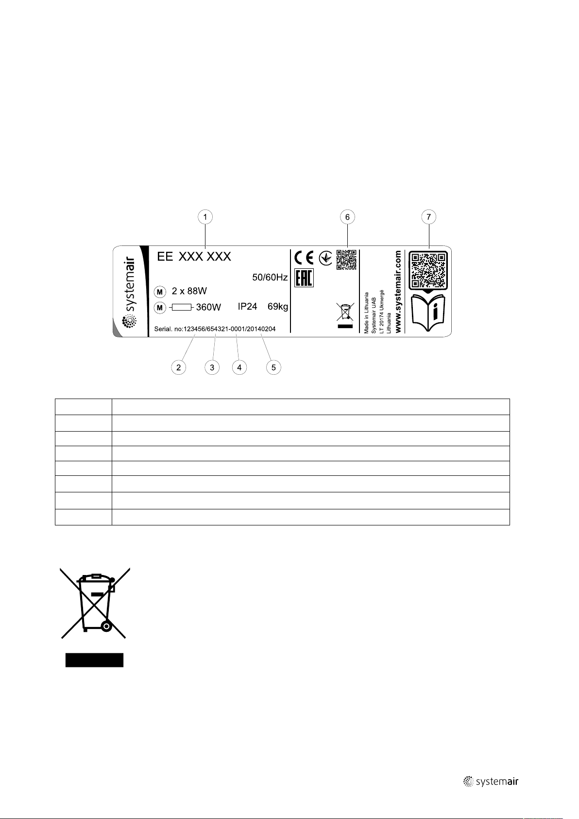
1.2 Type label
Before calling your service representative, make a note of the specification and production number from the type label,
which can be found next to the external connections and inside of the unit.
1
Position Description
1
2
3
4
5
6
7
Product code (product specification)
Product item number
Production order number
Serial number
Production date (YY.MM.DD)
QR code for manufacturing order (MO) number and software version
QR code for the spare parts list and documentation
1.3 Disposal and recycling
This product is compliant to the WEEE directive. When disposing the unit, follow your local rules
and regulations.
This product packing materials are recyclable and can be reused. Do not dispose in household
waste.
Fig. 1 Type label
2 Important Safety Information
• Observe and respect local conditions, regulations and laws.
• Safety elements may not be dismantled, circumvented or deactivated.
• Wear protective equipment during all work in the vicinity of the unit.
• Do not allow children to play with the device.
| Rev01
Page 6
| Important Safety Information
2
2.1 Intended Use
• Abide by the system-related conditions and requirements of the system manufacturer or plant constructor.
• Keep all the warning signs on the device and in a legible condition.
• The device is not to be used by persons (including children) with reduced physical, sensory or mental capabilities, or
lack of experience and knowledge, unless they have been given supervision or instruction.
• The system should operate continuously, and only be stopped for maintenance/service.
• Do not connect tumble dryers to the ventilation system.
• Make sure that filters are mounted before starting the unit.
2.2 Admonitions
Danger
• Make sure that the mains supply to the unit is disconnected before performing any maintenance or
electrical work!
• All electrical connections and maintenance work must be carried out by an authorized installer and in
accordance with local rules and regulations.
Warning
• This product must only be operated by a person who has suitable knowledge or training within this field
or carried out with the supervision of a suitably qualified person.
• Beware of sharp edges during mounting and maintenance. Use protective gloves.
Warning
• Risk of injury due to rotating parts that have not come to a complete standstill after mains supply to the
unit have been disconnected.
| Rev01
Page 7

Important Safety Information |
2.3 Declaration of Conformity
Manufacturer
Systemair UAB
Linų st. 101
LT–20174 Ukmergė, LITHUANIA
Office: +370 340 60165 Fax: +370 340 60166
www.systemair.com
hereby confirms that the following product:
Heat recovery ventilation unit: EE VTR 250/B
(The declaration applies only to product in the condition it was delivered in and installed in the facility in accordance
with the included installation instructions. The insurance does not cover components that are added or actions carried
out subsequently on the product).
Comply with all applicable requirements in the following directives:
• Machinery Directive 2006/42/EC
• Low Voltage Directive 2014/35/EU
• EMC Directive 2014/30/EU
• Ecodesign Directive 2009/125/EC
• RoHS Directive 2011/65/EU
The following regulations are applied in applicable parts:
3
1253/2014
1254/2014
327/2011 Requirements for fans above 125 W
The following harmonized standards are applied in applicable parts:
EN ISO 12100:2010
EN 13857
EN 60 335-1
EN 60 335-2-40
EN 62233
EN 50 106:2007
EN 61000-6-2
EN 61000-6-3
Requirements for ventilation units
Energy labelling of residential ventilation units
Safety of machinery - General principles for design - Risk assessment and risk reduction
Safety of machinery – Safety distances to prevent hazard zones being reached by upper or
lower limbs
Household and similar electrical appliances – Safety Part 1: General requirements
Safety of household and similar electrical appliances – Part 2-40: Particular requirements
for electrical heat pumps, air-conditioners and dehumidifiers
Measurement methods for electromagnetic fields of household appliances and similar
apparatus with regard to human exposure
Safety of household and similar appliances – Particular rules for routine tests referring to
appliances under the scope of EN 60 335-1 and EN 60967
Electromagnetic compatibility (EMC) – Part 6-2: Generic standards – Immunity for industrial
environments
Electromagnetic compatibility (EMC) – Part 6-3: Generic standards – Emission standards for
residential, commercial and light-industrial environments
Skinnskatteberg, 30-07-2017
Mats Sándor
Technical Director
| Rev01
Page 8
System curves
|
4
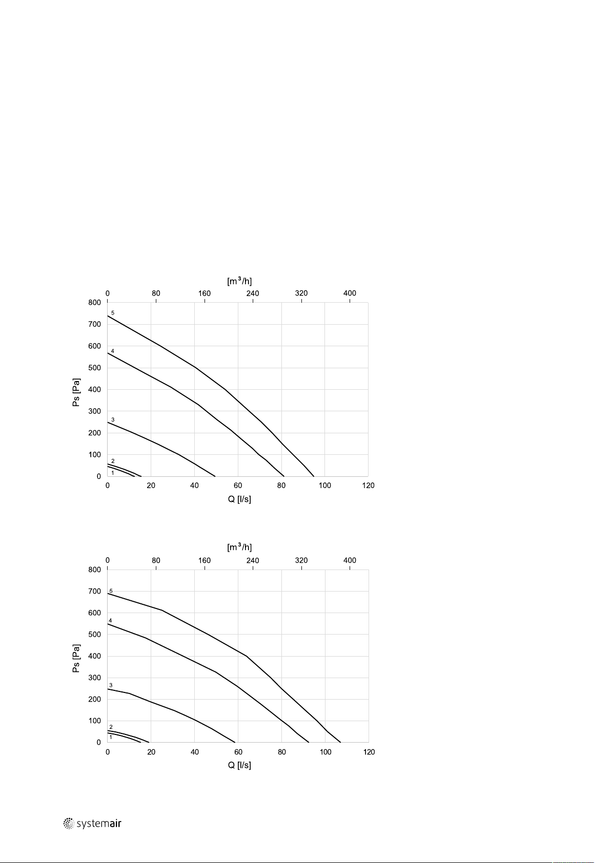
3 System curves
Every change in the pressure of the ventilation system, will result in a different airflow.
Each curve shows a different airflow level setting:
1. 16% (MINIMUM LEVEL)
2. 20% (LOW LEVEL)
3. 50% (NORMAL LEVEL)
4. 80% (HIGH LEVEL)
5. 100% (MAXIMUM LEVEL)
Airflow level settings can be changed in Service menu.
The pressure is affected by the filter type and differ with each filter combination.
System curves for each airflow level with standard filters shown bellow.
3.1 Supply air, F7/ePM1 60% type filter
3.2 Extract air, M5/Coarse 70% type filter
| Rev01
Page 9
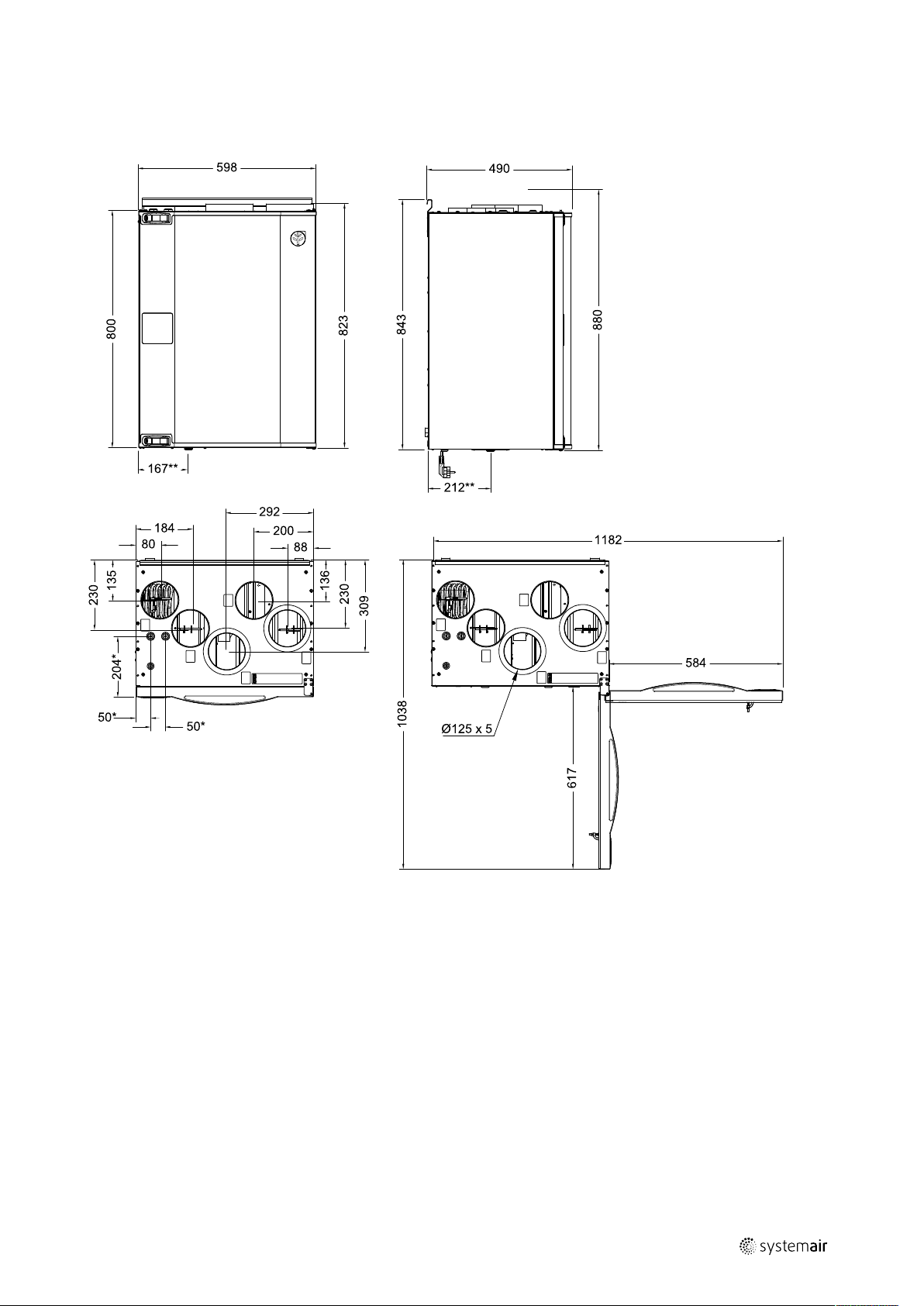
4 Technical Data
4.1 Dimensions and Weight, L model
Technical Data |
5
Fig. 2 Dimensions of left hand unit
* Water coil connections.
** Drainage.
The unit weight is 56 kg.
| Rev01
Page 10
| Technical Data
6
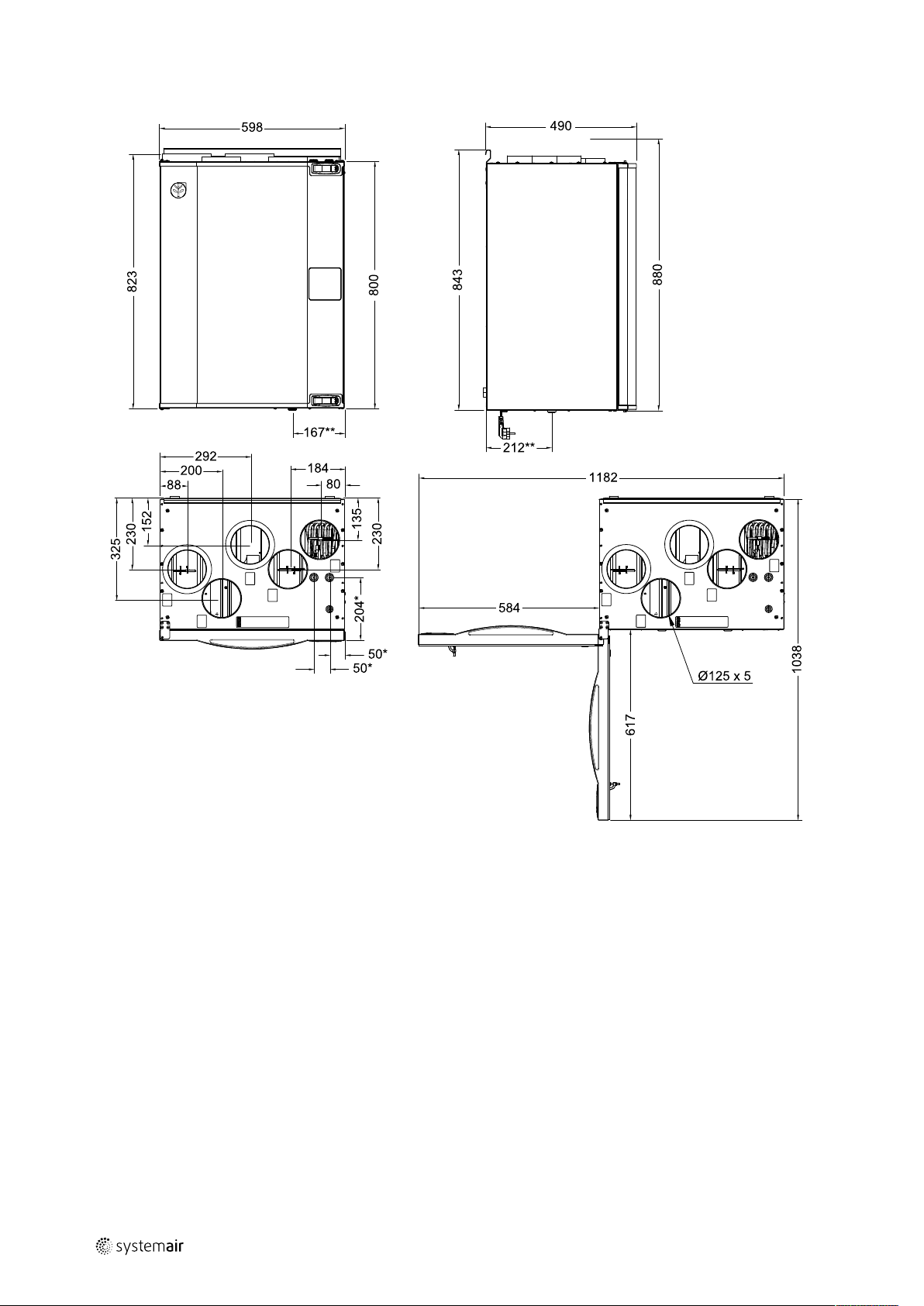
4.2 Dimensions and Weight, R model
Fig. 3 Dimensions of right hand unit
* Water coil connections.
** Drainage.
The unit weight is 56 kg.
| Rev01
Page 11
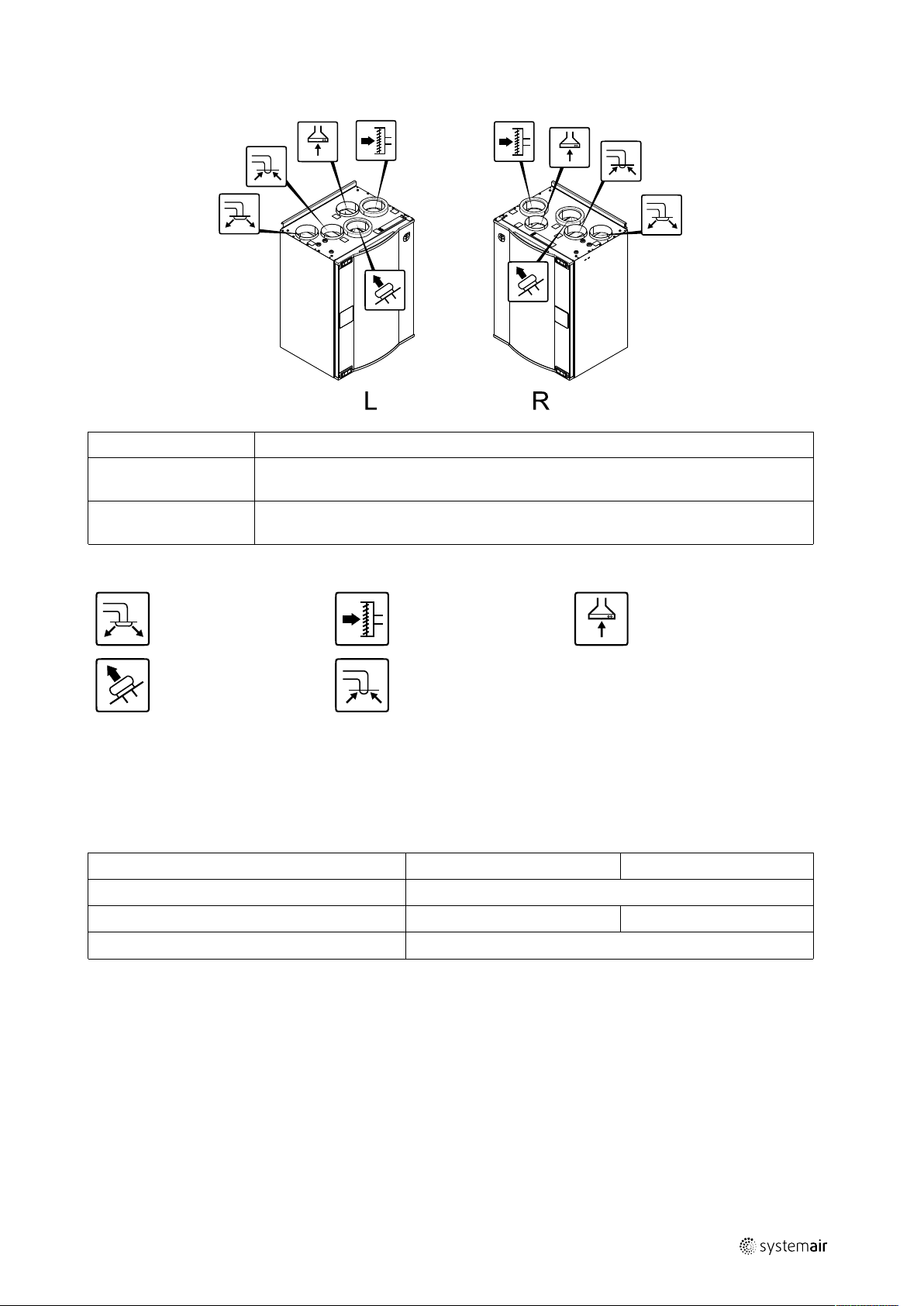
4.3 Connections Left and Right models
Position Description
R
L
Right hand model (Supply air connection is situated on the right hand side of the unit
viewed from the front)
Left hand model (Supply air connection panel is situated on the left hand side of the unit
viewed from the front)
Configuration |
7
Symbol
Description
Supply air
Exhaust air
Symbol
Description
Outdoor air Cooker hood air
Extract air
4.4 Power consumption and fuse size
EE VTR 250/B come with 500 W or 1000 W installed re-heater battery.
Table 1 Electrical data
Re-heater (W)
Fans (W)
Total power consumption (W)
Fuse (A)
500 W 1000 W
672 W 1172 W
5 Configuration
Symbol
172 W
10 A
Description
5.1 General
EE VTR 250/B has a modern touchscreen LCD control panel, simply known as HMI — Human Machine Interface. The
touchscreen display provides information about current state of the unit and allows you to control all system functions.
Settings are done by touching the icons or options. The touch screen is sensitive and it is not necessary to press too
hard.
5.2 Startup wizard
During the first power up of the unit, you will be asked to set:
| Rev01
Page 12
| Configuration
8
• menu language
• time and date
• import configuration file (if the Internet Access Module (IAM) with configuration file is available)
• airflow control type (Manual/RPM) and airflow level values
• heater type (None/Electrical/Water/Change-over)
The Startup Wizard cannot be skipped.
5.3 Common symbols
The following selection symbols are common and are present in most menu pages:
Back button to return to a previous
menu, located at the upper left corner
Up arrow to increase a value CANCEL Button to cancel changes
Down arrow to decrease a value
Some menus have more than one page. Touch page indicator in the top right corner to go to the next page. The first
number indicates current page number and the second number indicates a total number of pages available.
Many options show up in a form of the pop-up window. Select the option from the displayed list in the pop-up window
and press OK to confirm selection.
SET/OK
On and Off slider to activate or
deactivate a function. White bubble —
function is inactive, green bubble —
function is active.
Buttons to confirm changes
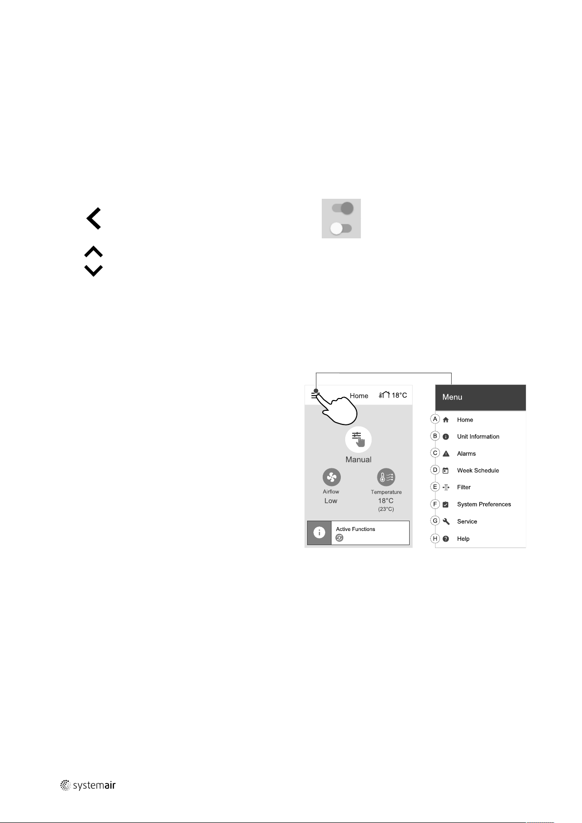
5.4 Menu overview
A.Return to home screen
B. Basic read-only information about the unit
C. Currently active alarms and alarm history
D.Configure and check week schedule
E. Check and change remaining time till filter change
F. General system preferences
G.Configuration of all system parameters
H.Help and troubleshooting menu
| Rev01
Page 13

5.5 Home screen
1. Drop-down menu list
2. Active user mode
3. Airflow settings
4. Temperature settings
5. Target temperature
6. Current measured temperature
7. Status bar
Configuration |
9
5.5.1 User modes
The first icon at the top of home screen shows currently active user mode. To change the user mode, touch the active
user mode icon (pos. 2) and select a new user mode from the list. The unit has 2 permanent and 5 temporary user
modes available for selection. Only one mode can be active at a time.
Settings of all modes can be modified in Service menu.
5.5.1.1 Permanent modes
Permanent modes are always active unless interrupted by temporary modes, activated user functions or alarms:
Icon Text
AUTO
MANUAL
Automatic airflow control. AUTO mode is available for selection when Demand
Control, Week Schedule and/or external fan control functions are configured,
otherwise AUTO mode icon won’t be visible in active user modes menu. AUTO
mode activates Demand Control, Week Schedule and/or external fan control
functions. Demand is available to choose as airflow setting in Week Schedule.
Manual selection of airflow levels. The unit can be set run at one out of four
available airflow speeds: Off/Low/Normal/High.
Note:
The fan can be set to OFF by activating Manual Fan Stop function in
Service menu.
Description
5.5.1.2 Temporary modes
Temporary modes are active only for a set period of time unless interrupted by active user modes, activated user functions or alarms:
| Rev01
Page 14

10
| Configuration
Icon Text
Sets speed of both supply and extract air fans to Low levels when user is away
HOLIDAY
CROWDED
AWAY
REFRESH
FIREPLACE
Settings of all modes can be modified in Service menu.
Temporary modes and user functions are active only for a set period of time after which they are terminated and the
unit changes back to a former AUTO or MANUAL mode, depending on which one was active before temporary mode or
user function was activated.
from home for a long period of time.
ECO mode is active.
Set duration in days.
Sets speed of both supply and extract air fans to maximum High levels and
temperature setpoint offset to –3 K when apartment is more crowded than usual.
Default temperature setpoint offset is –3 K.
Set duration in hours.
Sets speed of both supply and extract air fans to Low levels when user is away
from home for a short period of time.
ECO mode is active.
Set duration in hours.
Sets speed of both supply and extract air fans to maximum High levels to
replace indoor air with a fresh air in a short period of time.
Set duration in minutes.
Sets speed of supply air fan to High level and extract air fan to Low level to
increase air pressure within the apartment for better smoke extraction through
the chimney.
Set duration in minutes.
Description
Temporary modes can also be activated via digital input signal triggered by push button, presence detector, etc.
5.5.1.3 Digital input functions
Digital input functions always active while digital input is activated.
Icon Text
Central
Vacuum
Cleaner
Cooker Hood
Configurable
Digital Input
1
Configurable
Digital Input
2
Configurable
Digital Input
3
Function sets speed of supply air fan to High level and extract air fan to Low
level to increase air pressure within the apartment for better dust collection
through central vacuum cleaner.
Function can be activated via digital input — Central Vacuum Cleaner
Function.
Sets speed of both supply and extract air fans to Maximum level to increase
airflow in the cooker hood.
Function can be activated via digital input — Cooker Hood Function.
Configurable digital input for custom user function. Airflow levels for both fans
are freely configurable.
High–priority function.
Configurable digital input for custom user function. Airflow levels for both fans
are freely configurable.
Mid–priority function.
Configurable digital input for custom user function. Airflow levels for both fans
are freely configurable.
Low–priority function.
Description
Pressure
Guard
Configurable digital input for pressure switch connection. Airflow levels for both
fans are freely configurable.
5.5.1.3.1Configurable digital inputs
A custom airflow settings for supply and extract fans can be set and assigned to a digital input. Each fan can have a different airflow setting.
| Rev01
Page 15

Configuration |
Configurable digital input can be activated via signal triggered by push button, presence detector or any other external
device with digital output, such as Building Management Systems (BMS)
Configurable digital inputs are grouped in levels of priority, Configurable Digital Input 1 being the highest,
meaning it can’t be overwritten by other user functions.
5.5.1.4 Digital input and Mode hierarchy
User modes and functions have a different hierarchy. User functions activated via HMI or mobile APP, such as AWAY,
CROWDED, FIREPLACE, HOLIDAY and REFRESH, are interrupted by manual selection of AUTO and MANUAL fan modes.
A FIREPLACE function has the highest priority between user functions. Other functions activated via HMI/APP can interrupt each other.
If FIREPLACE function is hard-wired on the connection board and configured as digital input (DI) then it has a higher
priority than AUTO and MANUAL mode. Digital input for a FIREPLACE function has also a higher priority than other
hard-wired digital inputs (DI) for: AWAY, CENTRAL VACUUM CLEANER, COOKER HOOD, CROWDED, HOLIDAY or REFRESH.
11
Fig. 4 Hierarchy of user modes and digital inputs
Modes are listed from the highest to lowest priority; A — user modes that can be activated from the control panel; B —
user modes and functions activated via digital input
5.5.2 Temperature settings
Temperature can be set at SET TEMPERATURE menu accessible from the home screen by touching
TEMPERATURE icon with thermometer. Default temperature value is 18°C (range 12–30°C).
Use up and down arrows or a slider to change the value.
| Rev01
Page 16

| Configuration
12
Then touch the OK button to confirm changes.
Temperature set point is for room air temperature, supply air temperature or for extract air temperature depending on
which control mode is active. Default setting is Supply air temperature control.
Control mode of the temperature can be changed in Service menu.
5.5.2.1 ECO mode
ECO mode is a power saving function that can be activated in SET TEMPERATURE menu.
ECO mode function is available only when an internal heater is installed and configured.
While ECO mode is active, a temperature setpoint at which heater is activated is lowered to avoid activation of the heater during cold nighttime.
If the temperature is very low and the heater is activated during the nighttime (even with lowered temperature setpoint), then during the upcoming daytime indoor temperature will be increased using the heat exchanger so that accumulated heat could be used during the next cold nighttime, the lowered setpoint for the heater remains.
ECO mode will have impact for the following user
functions/modes if selected:
• AUTO mode
• MANUAL mode
• AWAY mode
• HOLIDAY mode
• CENTRAL VACUUM CLEANER function
• COOKER HOOD function
• FIREPLACE mode
ECO mode is always activated by the following modes:
• AWAY mode
• HOLIDAY mode
ECO mode is always deactivated by the following user
functions/modes:
• CROWDED mode
• REFRESH mode
• FREE COOLING function
5.5.3 Airflow settings
Airflow settings are available only in MANUAL mode. Click on fan icon on the main screen to enter SET
AIRFLOW menu.
Use up and down arrows or a slider to change the airflow value.
The airflow may be adjusted in these steps: Off/Low/Normal/High. These settings control output signals to the supply and extract fans.
Important
It is not recommended to set fan to Off in standard households. If manual fan stop is activated, the unit
should be provided with dampers in exhaust and fresh air ducts to avoid cold draught and risk of
condensation when the unit has been stopped.
The fan can be set to Off by activating Manual Fan Stop function in Service menu.
| Rev01
Page 17

5.5.4 Indoor Air Quality
The unit automatically controls indoor humidity and/or CO2levels by adjusting airflow setting. Airflow is
increased if air quality is decreasing.
Configuration |
13
Demand Control function is responsible for IAQ (Indoor Air Quality) regulation. Relative humidity (RH) and/or CO
sors are responsible for IAQ monitoring.
Indoor air quality (IAQ) indicator is available if AUTO mode and Demand Control function is activated.
IAQ levels:
• ECONOMIC: Actual IAQ value is below low IAQ set point.
• GOOD: Actual IAQ value is between low and high IAQ limits.
• IMPROVING: Actual IAQ value is above high IAQ set point.
Different airflow settings can be set for IMPROVING and GOOD IAQ levels in Service menu.
Setpoint for relative humidity and CO
level can be set in Service menu.
2
2
sen-
5.5.5 Status line
Status line located at the bottom area of home screen displays information about:
List of active alarms. See
chapter 5.7.2.3 for more
information.
Touching any of these lines will move you to the next page with more detailed list and information about each alarm or
active user function.
List of active user functions.
See chapter 5.6 for more
information.
5.6 Description of User functions
Icon Text
Heating
Heat recovery
Cooling
Cooling
recovery
Free cooling
Moisture
transfer
Defrosting
Description
Connected heater or pre-heater is active and air heating is in process.
Heat recovery from apartment is active.
Connected cooler is active and air cooling is in process.
Automatic cooling recovery is active when extract air temperature from
apartment is lower than outdoor air temperature and there is a cooling demand
(temperature setpoint is lower than outdoor air temperature).
No cooling recovery with heating demand. If the outdoor air temperature is
higher than then thee indoor air temperature and there is a heating demand,
function Free heating is activated instead.
Function decreases indoor air temperature by using only cool outdoor air during
nighttime to save energy consumption.
Function controls the rotation speed of the heat exchanger to prevent moisture
transfer to supply air due to high relative humidity in the extract air.
Function is only available for units with Rotating type heat exchanger.
Function prevents formation of the ice on the heat exchanger during cold
outdoor temperatures.
| Rev01
Secondary air
Warm air from the living space is used to defrost the heat exchanger using a
damper inside the outdoor air duct. The unit switches from outdoor air to
secondary air while the extract air fan stops and warm secondary air increases
the temperature inside the heat exchanger.
Page 18

14
| Configuration
Icon Text
Vacuum
cleaner
Cooker Hood
User lock
Configurable
Digital Input
1
Configurable
Digital Input
2
Configurable
Digital Input
3
Pressure
Guard
Description
Function sets speed of supply air fan to High level and extract air fan to Low
level to increase air pressure within the apartment for better dust collection
through central vacuum cleaner.
Function can be activated via digital input — Central Vacuum Cleaner
Function.
Always active while digital input is activated.
Sets speed of both supply and extract air fans to Maximum level to increase
airflow in the cooker hood.
Function can be activated via digital input — Cooker Hood Function.
Function indicates that the system is locked with a password and cannot be
edited or settings changed in any way. System must be unlocked first to make
changes.
Configurable digital input for custom user function. Airflow levels for both fans
are freely configurable.
High–priority function.
Configurable digital input for custom user function. Airflow levels for both fans
are freely configurable.
Mid–priority function.
Configurable digital input for custom user function. Airflow levels for both fans
are freely configurable.
Low–priority function.
Configurable digital input for pressure guard connection. Airflow levels for both
fans are freely configurable.
5.7 Main menu
5.7.1 Unit Information
A basic read-only information about status of the unit, configured components and inputs/outputs.
5.7.1.1 Components
Type and settings of heat exchanger, heater, cooler, extra controller.
5.7.1.2 Sensors
Values from sensors and load of fans (rpm).
5.7.1.3 Input Status
Status of configured analog, digital and universal inputs. Connected component type and raw value (volts) is displayed.
5.7.1.4 Output Status
Status of configured analog, digital and universal outputs. Connected component type and value (volts) is displayed.
5.7.1.5 Unit Version
Unit model name, manufacturer number, serial number and unit software versions for Mainboard, HMI and IAM.
5.7.2 Alarms
A detailed information about active system alarms and alarm log of last 20 events.
| Rev01
Page 19

Configuration |
5.7.2.1 Active Alarms
Alarm screen is empty if there are no active or logged alarms.
Press HELP button on the active alarm to access FAQ and troubleshooting (if available). Press ACKNOWLEDGE on the individual alarm to clear it. Depending on alarm type and the cause, it might be necessary to do a troubleshooting first to
acknowledge active alarm.
It may be not possible to clear the status of alarm if the cause of alarm is still present, as that would immediately trigger
alarm to return.
5.7.2.2 Alarms log
Alarm log allows to view last 20 alarms.
Each alarm contains information:
• Alarm name
• Date/time stamp
• Information if the alarm stops the unit or other note
5.7.2.3 Alarm list
Alarm name Explanation Do the following
Frost protection
Frost protection temperature
sensor
Defrosting error
Supply air fan rpm
Extract air fan rpm
Supply air fan control error
Extract air fan control error
Frost protection of return water in
heating coil.
• Alarm stops the unit and opens
the water valve completely.
Indicates malfunction of water
heater temperature sensor.
• Alarm stops the unit.
Indicates failure of pre-heater to
preheat the incoming outdoor air (in
case Extra controller is configured as
Preheater).
• Alarm stops the unit.
Rotation speed of the supply air fan
is lower than minimum required. Fan
malfunction.
• Alarm stops the unit.
Rotation speed of the extract air fan
is lower than minimum required. Fan
malfunction.
• Alarm stops the unit.
Flow or pressure alarm for supply air.
The pressure is bellow pressure limit.
• Alarm stops the unit.
Flow or pressure alarm for extract
air. The pressure is bellow pressure
limit.
• Alarm stops the unit.
The alarm will reset once the water
temperature reaches 13°C.
Check the water fluid temperature in
heating coil.
Check the circulation pump of water
heater. Contact your installation
company or place of purchase.
Check that frost protection
temperature sensor is connected
properly and cable is not damaged.
Contact your installation company or
place of purchase.
Check the pre-heater reset button.
Check the pre-heater cabling.
Contact your installation company or
place of purchase.
Defrosting error may be caused by
extremely low outdoor air
temperatures or pre-heater failure.
Check quick connectors of the fan.
Contact your installation company or
place of purchase.
Check quick connectors of the fan.
Contact your installation company or
place of purchase.
Check that air tube for pressure
sensor is connected properly and
cable is not damaged.
Contact your installation company or
place of purchase.
Check that air tube for pressure
sensor is connected properly and
cable is not damaged.
Contact your installation company or
place of purchase.
15
| Rev01
Page 20

| Configuration
16
Alarm name Explanation Do the following
Fire alarm
Emergency thermostat
Bypass damper
Rotor guard
Secondary air damper
Outdoor air temperature
sensor
Overheat temperature sensor
Supply air temperature
sensor
Fire alarm is active.
• Alarm stops the unit.
Indicates triggered overheat
protection (in case of installed
electric re-heater battery).
Indicates malfunction in bypass
damper.
Indicates a rotor malfunction.
No rotation guard signal for 180
seconds.
Secondary air defrosting failed.
Outdoor air temperature sensor
measures < 10°C in 2 sec after
defrosting
OR
Outdoor air temperature sensor
measures < 5°C in 5 min after
defrosting
Indicates outdoor air temperature
sensor malfunction.
Indicates overheat temperature
sensor malfunction.
Indicates supply air temperature
sensor malfunction.
Once the external Fire alarm is
disabled – alarm has to be
acknowledged and unit restarted.
A triggered manual or automatic
overheat protection (EMT) gives an
alarm in the control panel.
In case a manual overheat protection
is triggered, reset it by pushing the
reset button.
If the automatic overheat protection
is triggered, it will reset
automatically once the temperature
has dropped.
If the problem continues contact
your installation company or place of
purchase.
Disconnect the main power supply
for 10 seconds to reset control
function.
Power up the unit, an automatic
bypass damper test will be
performed.
If the alarm occurs again after
approximately 2 minutes – contact
your installation company or place of
purchase.
If the rotating heat exchanger has
stopped. Check the rotor belt.
If the heat exchanger is still rotating,
check that the quick connector for
the sensor is connected and that
there is an air gap of 5-10 mm
between the sensor and the magnet.
Adjust the gap if necessary.
If the alarm persists, the rotor sensor
may be faulty. Contact your
installation company or place of
purchase.
Check if secondary air damper is in
correct position.
Check that damper is connected
properly and cable is not damaged.
Contact your installation company or
place of purchase.
Check that sensor is connected
properly and cable is not damaged.
Contact your installation company or
place of purchase.
Check that sensor is connected
properly and cable is not damaged.
Contact your installation company or
place of purchase.
Check that sensor is connected
properly and cable is not damaged.
Contact your installation company or
place of purchase.
| Rev01
Page 21

Alarm name Explanation Do the following
Room air temperature sensor
Extract air temperature
sensor
Extra controller temperature
sensor
Efficiency temperature
sensor
PDM RH
PDM RH Extract air
temperature
Filter warning
Filter
Extra controller alarm
External stop
Manual fan stop active
Overheat temperature
Indicates room air temperature
sensor malfunction.
Indicates extract air temperature
sensor malfunction.
Indicates extra controller
temperature sensor malfunction.
Indicates efficiency temperature
sensor malfunction.
Indicates internal relative humidity
sensor malfunction.
Active: measured humidity = 0%
Returned: measured humidity > 5%
Indicates internal extract air
temperature sensor malfunction.
Active: measured temperature = 0°C
Returned: measured temperature >
5°C
Notification about filter change. Filter have to be replaced in one
Time for filter change. Change the filter.
Error from external device. Check if external device is connected
Unit is stopped by external signal. Operation is stopped by digital signal
Operation stopped, fans are in
manual mode and selected as OFF.
Temperature after reheater is too
high.
Active: (Overheat temperature
sensor measures > 55°C)
Returned: (Overheat temperature
sensor measures < 50°C)
Check that sensor is connected
properly and cable is not damaged.
Contact your installation company or
place of purchase.
Check that sensor is connected
properly and cable is not damaged.
Contact your installation company or
place of purchase.
Check that sensor is connected
properly and cable is not damaged.
Contact your installation company or
place of purchase.
Check that sensor is connected
properly and cable is not damaged.
Contact your installation company or
place of purchase.
Check that sensor is connected
properly and cable is not damaged.
Contact your installation company or
place of purchase.
Check that sensor is connected
properly and cable is not damaged.
Contact your installation company or
place of purchase.
month time. Please acquire new
filters.
Change filter according to the
instructions in the User Manual.
Details about filter retailers can be
found in Help menu.
properly and cable is not damaged.
Reset overheat protection on
electrical pre-heater. Contact your
installation company or place of
purchase.
from external remote device or
signal from building management
system.
Select another speed of fans (LOW /
NORMAL / HIGH) or AUTO mode in
HMI home screen.
Alarm is possible if supply airflow is
too low when the reheater is
switched on.
Check the supply airflow.
Check that intake grille is not
blocked.
Check that shut off damper for
outdoor air is open in operation.
Contact your installation company or
place of purchase.
Configuration |
17
| Rev01
Page 22

| Configuration
18
Alarm name Explanation Do the following
Low supply air temperature
CO₂
RH
Output in manual mode
Supply air temperature is too low.
Active: (Outdoor air temperature
sensor measures < 0°C) AND (Supply
air temperature sensor measures <
5°C)
Returned: (Supply air temperature
sensor measures > 10°C)
External CO
External relative humidity sensor
malfunction.
One or more of analogue outputs are
in manual mode.
sensor malfunction. Check that sensor is connected
2
Check the heat exchanger and reheater or refer to Point 2 in
“Troubleshooting” menu.
properly and cable is not damaged.
In case sensor wireless – check
RS485 gateway status and sensor
status in HMI.
Contact your installation company or
place of purchase.
Check that sensor is connected
properly and cable is not damaged.
In case sensor wireless – check
RS485 gateway status and sensor
status in HMI.
Contact your installation company or
place of purchase.
Check Service menu for Output
settings, and check all configured
outputs to be in Auto mode. If any
outputs in Manual - change back to
Auto mode.
Alarm Fire Alarm can be only activated with a digital signal from a smoke/fire detection system or similar. Digital input has to be configured as Fire Alarm for this alarm to work.
Digital output configured as Sum Alarm sends a generic signal every time the alarm is triggered, except for alarms Ex-
ternal stop, Output in manual mode and Manual Fan Stop. This signal does not specify the alarm type.
5.7.3 Week Schedule
The unit can be configured to operate at set airflow levels up to two time periods (00:00–23:59) on user
selected days.
Week Schedule is active only during AUTO mode.
5.7.3.1 Schedule airflow settings
Touch settings icon to go to SCHEDULE AIRFLOW SETTINGS menu. In this menu set airflow level for
scheduled and unscheduled periods. Available levels: Off, Low, Normal, High or Demand.
Set temperature setpoint offset for both periods (-10°C – 0°C).
Demand level is available only if Demand Control or External fan function is active.
5.7.3.2 Edit schedule
Touch icon at the bottom left corner of the screen to add a new schedule or press EDIT button to modify
already added schedule.
To configure the schedule:
1. Set the time. Touch the START TIME or END TIME values to change time. Use arrow buttons
or decrease value. Confirm with OK button.
Note:
Scheduled time can start but never end at midnight (00:00). The latest END TIME period is 23:59.
Scheduled time cannot go to the next day.
12 or 24 hour time format can be changed in System Preferences menu.
and to increase
| Rev01
Page 23

Configuration |
If necessary, activate second scheduled period and set up time.
2. Once time is set, click on the day(s) when schedule should be active. It is possible to set a separate schedule for each
day.
Already scheduled days are not available for selection for new schedules.
3. Confirm schedule with OK button.
Fig. 5 Week schedule example
Scheduled days are highlighted (pos. 1). First time period (pos. 2) and the second time period (pos. 3) are shown on the
right side of each schedule.
19
5.7.4 Filter
In this menu the remaining time until filter change is displayed. Editing is locked with a password, use
administrator password. See Password Settings in Service menu for more information.
Set duration of the filter until next change for period of 3–15 months in steps of 1 month. Default setting is 12 months.
A filter change notification is shown one month prior to filter change.
If a new filter period is selected and confirmed or filter alarm is acknowledged, the timer resets and starts counting from
the beginning.
Information what filter type is needed for change or where to order a new filter can be found in Help menu.
5.7.5 System Preferences
Configuration of unit location, language and time.
Change the following information:
• Language (default language is English)
• Country (default country is UK)
• Unit address (address, post code)
• Unit date and time, activate or deactivate summer/winter time switch.
Time will automatically change between summertime and wintertime according to European standard, based on
Greenwich time zone and set unit location.
Switch between 12 and 24 hours time format.
• Contact information: contractor, installer, service, phone, website, e-mail, etc.
• Display settings: screen brightness and screen behavior in standby mode.
5.7.6 Service
| Rev01
All unit parameters and settings can be changed in the Service menu.
The Service menu is locked by default and it is necessary to enter a password (default
password is 1111).
Page 24

| Configuration
20
5.7.6.1 Input
Configuration of inputs
Settings for analog, digital and universal input terminals on the main board and connection board, configuration of
functionality.
Table 2 Digital universal inputs available for selection
User modes
Central Vacuum Cleaner
Cooker hood function
External Stop
Extra controller Alarm
Change-over feedback
Fire Alarm
Configurable Digital
Input 1
Configurable Digital
Input 2
Configurable Digital
Input 3
Pressure Guard
Activation of specific user modes.
Activation of Central vacuum cleaner function.
Activation of Cooker Hood function.
Air handling unit is stopped by an external command.
Indication about an alarm in external controller. Used for Extra Heater/Cooler/
Preheater.
Used with Change-over systems. Indicate if the temperature of heating/cooling fluid
in the system is right.
Air handling unit is stopped due to fire. Can be used with smoke alarms or similar.
Activation of custom airflows set by user.
Activation of custom airflows set by user.
Activation of custom airflows set by user.
Digital input from a pressure guard component
Relative humidity and rotation speed signals from fans are already pre-addressed to specific terminals and cannot be
changed, all other inputs are free for configuration by commissioning. Inputs are free to be used for any purpose.
Universal input (UI) configured as universal analog input (UAI) can be configured for several inputs because multiple
sensors of the same type can be used. Universal analog inputs (UAI) have only selections for RH Sensor (RH), CO₂
Sensor (CO₂), Supply Air Fan Control (SAFC) and Extract Air Fan Control (EAFC) wired configurations.
Analog input (AI) temperature sensors are not allowed to be configured more than once.
Same user modes can be configured on multiple digital inputs (for example multiple bathrooms can be connected to different digital inputs with Refresh mode configured for each.
Digital inputs can be configured to be normally open (Normally Open (NO)) or normally closed (Normally Closed
(NC)). Default setting is Normally Open (NO). Not available for wireless inputs.
A time delay for user modes activated via digital input can be switched off or enabled. Time delay indicates how long
the user mode remains active after its duration of operation has expired.
PDM (pulse density modulation) input for relative humidity (RH) sensor on the main board is pre-adressed and cannot
be changed.
Table 3 Overview of input configuration
Analog inputs Digital inputs Universal analog inputs Universal digital inputs
Input type
Value
Compensation
Input type
Polarity
Value
Input type
Analog type
Value
Input type
Digital type
Polarity
Value
5.7.6.2 Output
Configuration of outputs.
Settings for analog, digital and universal output terminals on the main board and connection board, configuration of
functionality.
| Rev01
Page 25

Configuration |
Table 4 Digital outputs available for selection
Step controllers for
Heating/Cooling/Extra
controller
Sum Alarm
Outdoor-/Exhaust Air
Damper
Secondary Air
Activate Cooling
Interlock External fan
Control
Circulation pump
Heating/Cooling/Extra
controller
Fan output PWM (Pulse-width modulation) signal and triac output are already pre-addressed to specific terminals and
cannot be changed, all other outputs are free for configuration by commissioning. Outputs are free to be used for any
purpose.
Digital outputs are restricted by signal type and physical number of connections.
An output function is only allowed to be used once. Already used and configured terminal is greyed-out in the menu for
output type selection.
Heater/Cooler/Extra controller control signals.
Fault indicating output.
Outdoor-/Exhaust air damper control signal.
Secondary air damper control.
Cooling mode activation signal to an external system.
Automatic indication about prohibited external fan control (i.e. if defrosting is
activated).
Start/Stop signal to the circulation pump of the Heating/Cooling/Extra controller.
21
Analog and digital outputs have a selection for Auto/Manual modes and an adjustable value for Manual mode.
Manual mode selection overwrites all system related automatic functions. Analog output adjustable manual value
range is 0–10V and digital output values On/Off.
Table 5 Overview of output configuration
Analog outputs Digital outputs
Output type
Auto/Manual
Value
Output type
Auto/Manual
Value
5.7.6.3 Components
Configuration of connected components.
Heat Exchanger
• Choose heat exchanger type.
Available types: Rotating / Plate
• Activate or deactivate passive house function if heat exchanger type Rotating is selected.
Options: Yes / No.
• Choose bypass damper location if heat exchanger type Plate is selected. Default setting is based on unit type.
Supply / Extract
• Set actuator type. Default setting is based on unit type.
Range: 0–10 V / 2–10 V / 10–0 V / 10–2 V.
Heater
• Choose heater type. Each selection unlocks additional configuration options. Default setting is based on unit type.
Available types: None / Electrical / Water / Change-over.
• Set actuator type. Default value is 0–10 V.
Range: 0–10 V / 2–10 V / 10–0 V / 10–2 V.
• Set circulation pump temperature. Default setting is 10°C. This option is available if Water / Change-over heater
type is selected.
| Rev01
Page 26

| Configuration
22
Range: 0–20°C.
• Set circulation pump stop delay. Default setting is 5 minutes. This option is available if Water / Change-over heater type is selected.
Range: Off / 1–60 min.
Cooler
• Choose cooler type. Each selection unlocks additional configuration options. Default setting is None.
Available types: None / Water / Change-over.
• Set outdoor air temperature interlock. Default setting is 10°C.
Range: 0–20°C.
• Set actuator type. Default value is 0–10 V
Range: 0–10 V / 2–10 V / 10–0 V / 10–2 V.
• Set circulation pump stop delay. Default setting is 5 minutes. This option is available if Water / Change-over heater type is selected.
Range: Off / 1–60 min.
Extra controller
• Choose extra controller type. Each selection unlocks additional configuration options. Default setting is None.
Available types: None / Preheater / Heating / Cooling.
• Set temperature set point of the extra controller. Default value is 0°C.
Range: –30°C — 40°C.
• Set P-band. Default setting is 4°C.
Range: 1-60°C.
• Set I-time. Default setting is Off.
Range: Off / 1–240 sec.
• Set actuator type. Default value is 0–10 V.
Range: 0–10 V / 2–10 V / 10–0 V / 10–2 V.
• Set circulation pump temperature. Default setting is 0°C. This option is available if Preheater controller type is
selected.
Range: 0–20°C.
• Set circulation pump stop delay. Default setting is 5 minutes.
Range: Off / 1–60 min.
5.7.6.4 Control Regulation
Configure how the system is controlled.
Temperature Control
• Configure temperature controller. Choose control mode:
Available modes: Supply air temperature control / Room temperature control / Extract air temper-
ature control
Note:
Room temperature control mode requires an accessory to measure room temperature.
• Choose temperature unit. Default setting is Celsius.
Available units: Celsius / Fahrenheit
• Set P-band. Default setting is 20°C. Set I-time. Default setting is 100 sec.
• Configure SATC Split for cooler (0–20%), heat exchanger (25–60%) and heater (65–100%) output settings.
Range: 0–100%.
• Configure cascade control setpoint for min/max supply air temperature, P-band, I-time.
| Rev01
Page 27

Only available for Room temperature control / Extract air temperature control modes.
ECO mode
• Configure ECO mode settings. Set heater offset. Default setting is 5°C.
Range: 0–10°C.
Fan Control
• Configure airflow and fan settings. Select fan control (airflow) type. Default setting is Manual (%).
Available types: Manual (%) / Manual rpm / Flow (CAV) / Pressure (VAV) / External
Configuration |
23
Setting
Airflow
Manual RPM Flow (CAV)
%
rpm
l/s, m
3
/h, cfm
Pressure
(VAV)
Pa %
External
measurement
unit.
P-Band
–
0–3000 rpm 0–500 Pa
–
Default setting: 150 Pa
I-time
-
Off / 1–240 sec.
Default setting: 5
Off / 1–240 sec.
Default setting: 5 sec.
–
sec.
Airflow level
16-100% 500–5000 rpm
Sensor range (airflow unit)
0–100%
settings for each
level: MAXIMUM
LEVEL, HIGH
LEVEL, NORMAL
LEVEL, LOW
LEVEL,
MINIMUM LEVEL
Manual Fan Stop — turn on or off manual fan stop, this function enables manual fan stop from HMI. Default setting
is OFF.
Pressure
Sensors —
configure sensor
voltage relation
to pressure.
Set value at
which fan alarm
occurs. Default
setting is None
- -
Supply air fan control sensor:
Pressure at 0V: 0-500 Pa, default
setting 0 Pa
Pressure at 10V: 0-2500 Pa, default
setting 500 Pa.
Extract air fan control sensor:
Pressure at 0V: 0-500 Pa, default
setting 0 Pa.
Pressure at 10V: 0-2500 Pa, default
-
setting 500 Pa
Set K factor for
supply air fan
and extract air
fan. Default
- - SAF K-Factor
range: 0–1000
EAF K-Factor
range: 0–1000
- -
settings are
based on unit
type.
Outdoor
Compensation
A purpose of this function is to protect the unit from freezing by creating an unbalanced airflow
at extreme winter temperatures or to limit supply of cold/hot outdoor air at extreme winter/
summer conditions with balanced ventilation.
Function operates by lowering the speed of supply air fan (SAF) or both supply and extract air
fans (SAF/EAFC) by value set in Stop Compensation Value setting (adjustable from 0% to
50%) if the outdoor air temperature (OAT) drops below adjustable value set in Start
Compensation Temperature setting (during winter from 0 °C to -30 °C / during summer
from 15 °C to 30 °C). This compensation reaches the maximum as soon as the outdoor air
temperature reaches the adjustable value set in Stop Compensation Temperature setting
(during winter from 0 °C to -30 °C / during summer from 15 °C to 30 °C)
| Rev01
Page 28

| Configuration
24
Important
Changing the airflow type does not change P-band value automatically. P-band value have to be changed
manually after changing the airflow type.
Demand Control
Configure indoor air quality sensors. Once sensor(s) are configured, Demand Control function is activated by choosing
AUTO mode in home screen.
• Activate or deactivate CO
Set CO
sensor setpoint. Default setting is 800 ppm (parts per million in atmosphere). Normal atmospheric CO2con-
2
centration is 400 ppm. Range: 100–2000 ppm.
Set P-band, default setting is 200 ppm. Range: 50–2000 ppm.
Set I-Time, default setting is Off. Range: Off/1–120 sec.
• Activate or deactivate RH sensor. Default setting is Off.
Set humidity setpoint in summer, default setting is 60%. Range: 1–100%.
Set humidity setpoint in winter, default settting is 50%. Range: 1–100%.
Set P-band, default setting is 10%. Range: 1–100%.
Set I-time, default setting is Off, Range: Off/1–120 sec.
• Select airflow level for Improving Air Quality. Range: Normal / High / Maximum.
• Select airflow level for Good Air Quality. Range: Low / Normal.
sensor. Default setting is Off.
2
Moisture Transfer Control
Note:
Setting is available if heat exchanger type is set as Rotating. It is highly recommended to leave default
values for P-band and I-time. They should be changed only by installer and trained staff.
• Activate or deactivate relative humidity transfer functionality. Default setting is On.
• If Moisture Transfer Control is activated, configure:
Setpoint, default setting is 45% humidity. Range: 1–100% RH.
Set P-band, default setting is 4g/kg. Range: 1–100g/kg.
Set I-time, default setting is Off. Range: Off/1–120 sec.
Defrosting Control
Note:
Setting is available if heat exchanger type is set as Plate.
The unit is equipped with an automatic defrost function that is activated when there is risk of icing in the area around
the heat exchanger.
• Select defrosting mode. Default setting is Normal.
Soft
Normal Apartments or houses with normal humidity
Hard
1
In newly constructed houses it might be necessary with a higher defrost level during the first winter period.
• Set by-pass location. Default setting is based on unit configuration.
Supply / Extract.
• Set if secondary air is allowed. Default setting is Off.
Dry areas, such as warehouse buildings with few people or industrial
buildings that don’t use water in their production process.
1
Buildings with very high humidity level.
| Rev01
Page 29

Configuration |
Off / On.
Cooling Control
• If the outdoor air is warmer than the extract air and the supply air is above the setpoint, cooling recovery occurs. This
condition blocks the heat regulation process. Activate or deactivate cooling recovery. Default setting is On.
Set cooling limit. Cooling recovery is allowed if extract air temperature is lower than outdoor air temperature by a set
limit (default setting is 2K) and cooling demand is present.
• Configure status, temperature and duration of free cooling. Activate or deactivate free cooling . Default setting is
Off.
Set supply and extract air fan levels during free cooling. Default setting is Normal. Range: Normal / High /
Maximum.
Set start condition. Outdoor daytime temperature for activation, default setting is 22°C. Range: 12–30°C.
Stat stop conditions. Extract/Room temperature, default setting is 18°C. Outdoor high temperature limit, default set-
ting is 23°C. Outdoor low temperature limit is 12°C. Start and stop time.
5.7.6.4.1Finding RPM for desired airflow
It is necessary to set fan RPM (revolutions per minute) for each airflow level to control airflow by changing fan speed.
Fan speed differ for each household because of different unit size, duct system and system pressure. In order to find
correct fan speed, external tool must be used at Systemair website.
1. Go to Systemair website and find your unit.
2. Go to Diagram tab and type in desired airflow values in l/s, m
sure drop in duct system (if this value is not know, type in 100 Pa for both supply and extract air)
3
/h, m3/s or cfm for supply and extract air. Input pres-
25
Fig. 6 Example of airflow and external pressure selection
3. See calculated speed values in revolutions per minute (rpm) for both supply and extract air in the table bellow
diagrams.
Fig. 7 Example speed for supply and extract air
4. Use this procedure to find fan speed for all airflow levels: MINIMUM LEVEL, LOW LEVEL, NORMAL LEVEL, HIGH LEV-
EL, MAXIMUM LEVEL.
5. Finally in the control panel go to Service menu, enter the password, then go to Control Regulation → Fan
Control. Choose RPM as airflow type and in sub-menu Airflow Level Settings enter calculated fan speed values for each level.
5.7.6.5 User Modes
Set airflow level, duration and offset for each user mode.
Set supply and extract air fan levels, default duration and temperature offset where available for user modes:
• Away
• Central Vacuum Cleaner
• Cooker Hood
• Crowded
• Fireplace
• Holiday
• Refresh
| Rev01
Page 30

| Configuration
26
• Configurable Digital Input 1
• Configurable Digital Input 2
• Configurable Digital Input 3
• Pressure Guard
5.7.6.6 Communication
Configure Modbus and wireless settings
Modbus
• Set Modbus address. Default setting is 1.
• Set baud rate. Default setting is 115200.
• Set parity. Default setting is None. Range: None / Even / Odd.
• Set stop bits. Fixed value: 1.
• Shows Smartly-Gateway state.
HMI Address
• When more than one control panel is connected to the unit, it is important that each control panel would have a different address number. This menu displays current HMI address.
For more information see 8.2 Multiple control panels, page 36.
WLAN Settings
WLAN settings are for connection of the Internet access module (IAM) accessory.
Internet access module (IAM) is a device that allows to connect to the unit and control it via a mobile application or directly from the computer.
• Shows current connection status.
• Shows network name to which the internet access module is connected.
• Scan for networks — use this search function to find your local protected network. Detailed procedure is described bellow.
Connecting the IAM to wireless network
1. If your wireless router does not support WPS, Wi-Fi connection should be set up manually. Therefore you need to
find Wi-Fi name and add password using control panel.
2. In control panel go to Service -> Communication -> WLAN settings menu.
3. Press Scan for networks button. IAM will search for available Wi-Fi networks (should not take longer than one
minute).
4. After search is complete, find the network name to which IAM should connect and select it. Wi-Fi network should
be password protected, otherwise IAM can't connect to Wi-Fi network.
5. After required Wi-Fi name selection, password pop-up window appears in control panel screen. Insert your Wi-Fi
network password.
6. If password is correct and connection to Wi-Fi network is successful, IAM will establish connection to server auto-
matically. The LED of IAM will start blinking slowly in green colour.
• Reset WLAN settings when needed.
5.7.6.7 Logs
Information about alarms, fans and parameters are stored in Logs menu.
Fans Levels
• Time counter for each supply air fan level duration is displayed. Counted and total time. Reset counted time.
Level 1: 0%
Level 2: 1–29%
Level 3: 30–44%
| Rev01
Page 31

Configuration |
Level 4: 45–59%
Level 5: 60–100%
Parameters
• Select parameter type, position in y-axis, period from 60 minutes to 2 weeks and then create a graph based on
stored data by touching icon in the top right corner
available in mobile application)
. Export parameters data by touching arrow button . (only
5.7.6.8 Unit backups
Menu for restoring factory settings or importing/exporting configuration file from/to the Internet Access
module (IAM).
• Touch Factory settings menu to restore factory configuration and parameters. This will also overwrite changed
password. You will be asked to confirm the task before proceeding.
Note:
This selection will automatically restart the unit. The Startup Wizard have to be re-done after restart.
• Touch Save current configuration to IAM option to save your current system configuration file to the connected Internet Access Module.
• Touch Download current configuration from IAM to download configuration file from the connected Internet
Access Module.
• Touch Set User Safe Configuration option to store current settings in the unit memory as a backup. It can later
be used as a fail-safe configuration copy in addition to factory settings.
• Touch Activate User Safe Configuration option to restore the backup copy of system settings from the unit
memory.
27
5.7.6.9 Password Settings
Service level is always locked with a password. Other menu levels have a separate option for locking. If password requirement is activated for different menu levels, these are unlocked with the administrator password.
Choose what menus should be locked or not.
5.7.7 Help
FAQ, troubleshooting of alarms, contact information for support is provided in this menu.
• Service partner — information about service partner.
• Company
• Telephone
• Homepage
• Email
• User modes— detailed description of all user modes.
• Functions— detailed description of different user functions.
• Alarms— detailed description of all alarms.
• Troubleshooting— information about all different possible malfunctions.
| Rev01
Page 32

Service
|
28
6 Service
6.1 Warnings
Danger
• Make sure that the mains supply to the unit is disconnected before performing any maintenance or
• All electrical connections and maintenance work must be carried out by an authorized installer and in
Warning
• This product must only be operated by a person who has suitable knowledge or training within this field
• Beware of sharp edges during mounting and maintenance. Use protective gloves.
Warning
• All though the mains supply to the unit has been disconnected there is still risk for injury due to rotating
electrical work!
accordance with local rules and regulations.
or carried out with the supervision of a suitably qualified person.
parts that have not come to a complete standstill.
Important
• The installation of the unit and complete ventilation system must be performed by an authorized installer
and in accordance with local rules and regulations.
• The system should operate continuously, and only be stopped for maintenance/service.
• Do not connect tumble dryers to the ventilation system.
• Duct connections/duct ends must be covered during storage and installation.
• Make sure that filters are mounted before starting the unit.
| Rev01
Page 33

6.2 Internal components
Service
|
29
Position Description
1
2
3
4
5
6
7
8
9
10
11
12
13
Mounting bracket
External connections
Extract air fan
Supply air filter
Extract air filter
Main print card
Rotating heat exchanger
Supply air fan
Supply air sensor
Outdoor air sensor
Relative humidity/Extract air temperature sensor
Overheat protection sensor
Internal electrical re-heater
6.2.1 Component descriptions
6.2.1.1 Fans
Fig. 8 Internal components
Fans have an external EC type rotor which can be steplessly controlled individually 16–100%. The motor bearings are
life time lubricated and maintenance free. It is possible to remove the fans for cleaning, see “User Manual” for more
information.
| Rev01
Page 34

Service
|
30
6.2.1.2 Filters
The factory installed filters are of filter quality F7/ePM1 60% for the supply air and M5/Coarse 70% for the extract air
filter. The filters need to be replaced when polluted. New sets of filters can be acquired from your installer or
wholesaler.
6.2.1.3 Heat exchanger
EE VTR 250/B is equipped with a highly efficient, rotating heat exchanger. Required supply air temperature is therefore
normally maintained without adding additional heat.
The heat exchanger is removable for cleaning and maintenance, see “User Manual” for more information.
6.2.1.4 Main circuit board
The main circuit board controls all functions and the unit.
It is possible to connect external accessories to a free terminals on the main circuit board.
6.2.1.5 Temperature sensors
Four temperature sensors (NTC, 10 kΩ at 25°C) are included in the unit from factory and positioned in the corresponding air chambers.
The sensors are connected to the main print card. See wiring diagram for more information.
6.2.1.6 Electrical Re-heater battery
The re-heater battery is positioned in the supply air chamber.
The re-heater is activated by a relay and switches on if the supply air temperature is lower than the set point and
switches off if one or more of the following conditions are met:
1. If the supply air temperature is above the set point.
2. If the over heat protection is activated or the sensor is malfunctioning.
3. If the emergency thermostat is triggered or broken.
4. If the supply air sensor is in error state.
5. If the supply air fan is not running.
6. If the heater is set to disabled in the menu.
6.2.2 Overheat protection reset button
If the supply air temperature is low, it can indicate that the over heat protection is triggered. The overheat protection can be reset by pressing the reset
button (1).
6.3 Electrical connections
The EE VTR 250/B is wired internally from factory.
Fig. 9 Overheat protection reset button
| Rev01
Page 35

Service
The electrical connection box can be found on the supply air outlet side of the unit. The print card can easily be taken
out from the unit, without using tools.
6.3.1 Main board layout
The EE VTR 250/B is equipped with built-in regulation and internal wiring.
The figure shows the main circuit board. See wiring diagram for more information.
|
31
Position Description
MB
CB
1
2
3
4
5
6
7
8
9
10
11
12
Main circuit board
Connection to the external connection box
Terminals for a heater
Terminals for a TRIAC
Terminals for the mains power supply
Terminals for power supply of extract air fan
Terminals for power supply of supply air fan
Terminals for internal relative humidity/temperature sensor
Analog input 1 — Outdoor air sensor
Analog input 2 — Supply air sensor
Analog input 3 — Freely configurable
Analog input 4 — Freely configurable / Overheat temperature sensor (units with
heater)
Analog input 5 — Freely configurable
Digital input 1 — Rotor guard sensor (VSR, VTR units)/ Damper signal (VTC units)
Fig. 10 Main circuit board connections
| Rev01
Page 36

| Troubleshooting
32
Position Description
13
14
15
16
17
Digital input 2 — Freely configurable / Cooker hood (VTR 150/K unit)
Analog output 2 — Freely configurable / Electrical heater controller (VTC 700 unit)
Analog output 1 — Rotor of the heat exchanger (VSR, VTR units) / Damper control
(VTC units)
Terminals for speed control of extract air fan
Terminals for speed control of supply air fan
7 Troubleshooting
If problems should occur, please check the items below before calling your service representative.
Malfunction
Fans do not start
Reduced airflow
Action
1. Check the HMI for alarms.
2. Check that all fuses and fast couplings are connected (main power supply and fast
couplings for supply and extract air fans).
3. Check that the week schedule is ON and running in AUTO mode. The week schedule
might be in OFF mode with the air flow set to OFF (chapter 5.7.3).
1. Check the HMI for alarms. Some alarms can reduce the airflow to LOW if active.
2. The unit could be in defrost mode. This reduces the fan speed and in some cases shuts
down the supply air fan completely during the defrosting cycle. The fans go back to
normal after finished defrosting. There should be a defrosting function icon visible in the
APP or HMI home screen if defrosting is active.
3. If the outdoor air temperature is below 0°C (Outdoor air temperature sensor (OAT)
measures < 0°C) outdoor airflow compensation function can be active (if enabled). Fan
speed (Supply or Supply/Extract air fans) is linearly reduced for decreasing outdoor air
temperature.
4. Check if temporary user mode that reduces airflow is not activated, for example AWAY,
HOLIDAY, etc. Also check digital inputs CENTRAL VACUUM CLEANER and COOKER HOOD.
5. Check setting of airflow in the HMI.
6. Check week schedule settings (chapter 5.7.3).
7. Check filters. Is change of filters required?
8. Check diffusers/louvres. Is cleaning of diffusers/louvres required?
9. Check fans and heat exchange block. Is cleaning required?
10.Check if the buildings air intake and roof unit (exhaust) have been clogged.
11.Check visible duct runs for damage and/or build up of dust/pollution.
12.Check diffuser/louvre openings.
The unit cannot be
controlled (control
functions are stuck)
1. Reset control functions by pulling out the plug for 10 seconds.
2. Check the modular contact connection between the HMI and the main printed circuit
board.
| Rev01
Page 37

Troubleshooting |
33
Malfunction
Low supply air
temperature
Noise/vibrations
Action
1. Check the display for alarms.
2. Check the active user functions in HMI screen if Defrosting function is running.
3. Check set supply air temperature in the HMI.
4. Check if ECO mode is activated in HMI (it is a power saving function and prevents the
heater from activating).
5. Check if user modes HOLIDAY, AWAY or CROWDED are activated in the HMI or via a
hardwired switch.
6. Check the analogue inputs in the service menu to verify that the temperature sensors
are functioning correctly.
7. In case of installed electrical/other re-heater battery: Check if the overheat protection
thermostat is still active. If necessary, reset by pressing the red button on the front plate
of the electrical re-heater.
8. Check if the extract filter must be changed.
9. Check if the unit has a re-heater battery connected. At very cold outdoor conditions an
electrical or water heating battery might be necessary. A re-heater battery can be
acquired as an accessory.
1. Clean fan impellers.
2. Check that the screws holding the fans are tightened.
3. Check that the anti vibration lists are fitted to the mounting bracket and to the back of
the unit.
4. Check that the rotor belt is not slipping if the unit has rotating heat exchanger.
| Rev01
Page 38

Accessories
|
34
8 Accessories
EE VTR 250/B have many available accessories that can be used to expand functionality of the unit and increase comfort level.
Recommended accessories can be always found at Systemair website www.systemair.com by searching the article
number or the name of the desired accessory.
8.1 Internet Access Module (IAM)
Internet access module is a device that allows to connect to the unit and control it via a mobile application or directly from the computer and receive automatic updates.
The Cloud is a mediator between the user and the unit. To access your unit
via Cloud, it has to be connected to the internet via Internet Access Module.
Component/product — Article number:
• Internet Access Module (IAM) – 211243
SAVE T ouch Cloud
8.1.1 Setting up remote control of the unit
| Rev01
Page 39

Accessories
|
35
Note:
The internet access module uses TCP port 8989. Make sure it is not blocked.
Description
A.Connect the Internet Access Module (IAM) to the mainboard with included RJ10 cable.
B. Power up the IAM with included power supply cable and adapter (230 V~).
C. Enable access to the internet. Three options are available:
• C1 — Activate WPS function on your router (if available) and press the button on the Internet Access Module for 5
seconds.
• C2 — Plug one end of the Ethernet cable to the RJ45 socket on IAM and the other end to any free Ethernet socket
on your router. The connection will be established automatically.
• C3 — Set up connection to your Wi-Fi through Communication menu in control panel.
D.Access Systemair mobile application. Two options are available:
• D1 — Download and install Systemair mobile application on your device. Systemair mobile application is available
for both Android and iOS mobile operating systems.
• D2 — Systemair web application does not require installation and can be accessed directly through the website
(homesolutions.systemair.com ) by using any web browser.
E. Launch the application. In the login screen enter your unique UNIT ID which can be found on the back label of IAM or
on additional label.
Press LOG IN button.
It is required to create a unique password when connecting to IAM for the first time. Touch Change password but-
ton. In the next menu screen enter your new password, confirm it and touch SET PASSWORD button. To finalize password creation, click the button on the IAM. Wait for a message to pop up in your app telling that password was
changed.
Touch BACK button to return to the previous login screen. Enter the newly created password and touch LOG IN
button.
For more information read the manual that comes with the accessory.
| Rev01
Page 40

Accessories
|
36
Table 6 LED indicator codes
WLAN
Connected
Disconnected
Connected
—
—
—
Fast blinking — every 500 milliseconds. Slow blinking — every 2 seconds.
Ethernet Cloud
—
—
—
Connected Not Connected
Disconnected Disconnected
Connected Connected
Not Connected Blinks fast
Disconnected Blinks slow
Connected
RED LED GREEN LED
—
—
—
—
—
—
Blinks slow
Blinks fast
Blinks fast
Blinks slow
8.2 Multiple control panels
Multiple control panels (up to 10) can be connected to one unit with the help of diverting plugs. A single diverting plug
allows to connect two control panels. A diverting plug can be connected to another diverting plug to further increase
the number of control panels that can be connected simultaneously.
Note:
• The number of control panels that can be powered from the unit decreases if other equipment is
connected to the unit.
• A single active control panel draws 50 mA. The main board supplies up to 250 mA. If no other accessories
use 24 V power supply from the unit, up to 5 control panels can be connected without a need of external
power supply. In order to connect more than 5 control panels, an external power supply is required.
Control panel is available in black or white colour.
• DP — diverting plug
• HMI — control panel
Component/product — Article number:
• CE/CD-diverting plug 4pin — 37367
• CEC Cable w/plug 12m — 24782
• CEC Cable w/plug 6m — 24783
• HMI White — 138077
• HMI Black — 138078
Installation and connection
1. Connect diverting plug to the socket dedicated for external control panel (HMI) or Internet access module (IAM).
2. Plug in control panels to diverting plug(s) using recommended cables or any cable with RJ22 type plugs.
Note:
The maximum supported cable length is 50 meters.
Configuration
1. Go to Service menu
2. Enter password (default 1111)
3. Go to Communication ⇒ HMI Address and change the address number. Repeat these steps for each connected
control panel.
Each control panel must have it’s own unique address number. No control panel should have the same address value
to function properly.
| Rev01
Page 41

| Rev01
Page 42

Systemair UAB
Linų st. 101
LT–20174 Ukmergė, LITHUANIA
Phone +370 340 60165
Fax +370 340 60166
www.systemair.com
EE VTR 250/B · · · en_GB · 2019-08-20 · Rev01
 Loading...