

Page 1
Callender and temperature settings
LEDs and buttons – navigating the menus – (change parameters) .................. 2
Operator's level - tree structure ..................................................................................... 3
Running mode – Auto/On/O ........................................................................................ 3
Alarm – cancel, acknowledge ......................................................................................... 4
Setting of temperature ...................................................................................................... 5
Modication of outdoor compensated supply temperature .............................. 5
Setting of ows - Flow control ........................................................................................6
Setting of ows - Pressure control .................................................................................7
Schedule settings ................................................................................................................ 8
Calender settings (time, date, weekday) .....................................................................8
Setting of holidays .............................................................................................................. 9
Setting of extended running........................................................................................... 9
Setting of min/max supply air temperature ...........................................................10
Restore Systemair factory settings or latest user parameters
and settings ......................................................................................................................... 11
Annex 1A7 for the User manual
Software versions 3.2 , 3.3, 3.4 and 3.6
Fans | Air Handling Units | Fire Safety | Air Distribution Products | Air Curtains and Heating Products | Tunnel fans
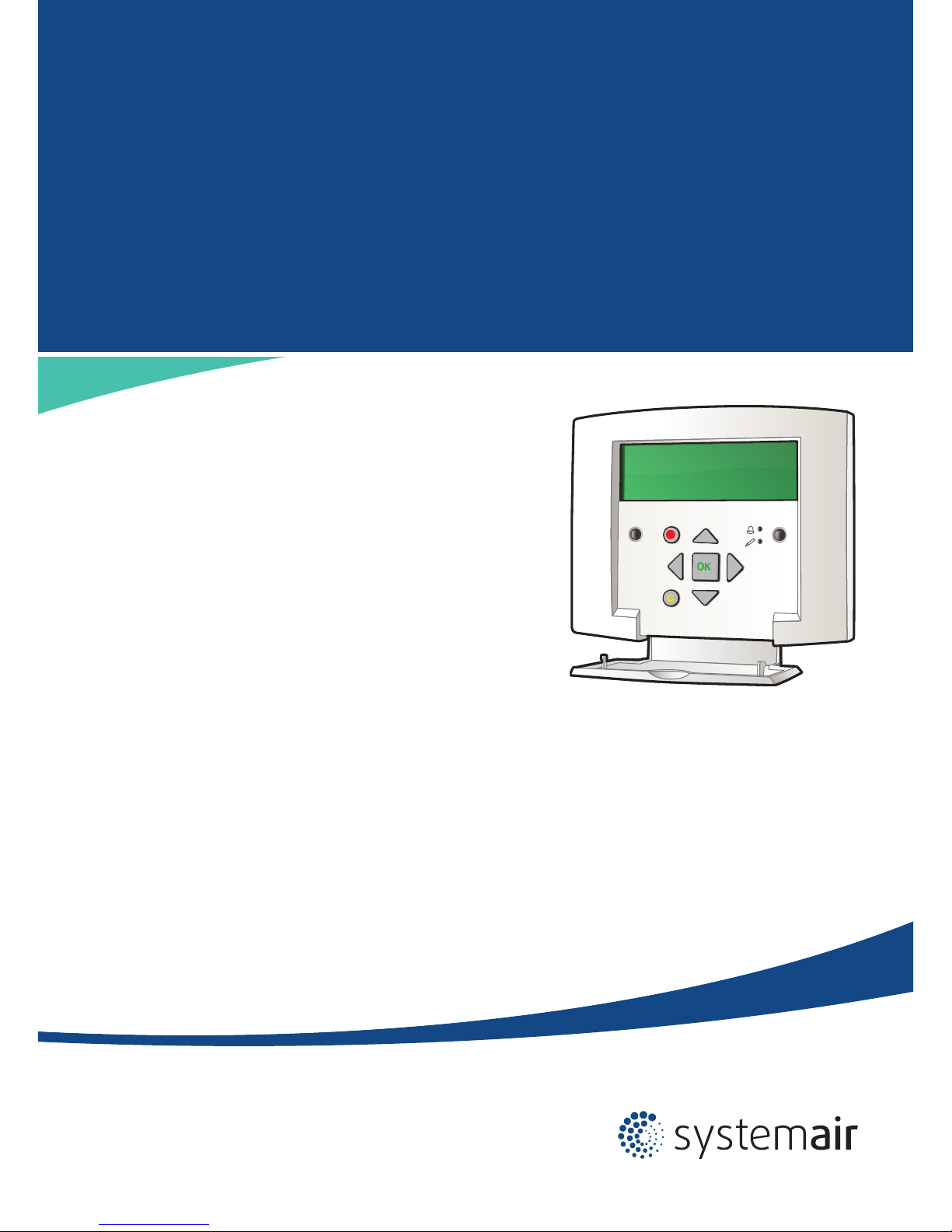
Operator's Guide for Systemair E 28 Controller
in large air handling units type:
Geniox, DV, TIME, DV Compact
Page 2
2
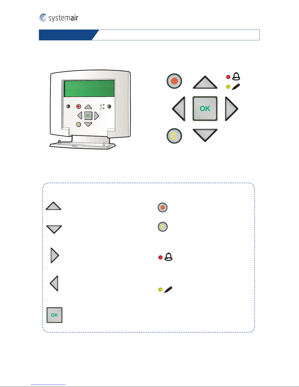
LEDs and buttons – navigating the menus – (change parameters)
UP:
Move to a higher menu line
(Increase value of the parameter)
The menus are organised in a horizontal tree structure – upper left corner is start
DOWN:
Move to a lower menu line
(Decrease value of the parameter)
RIGHT:
Move right to a lower menu level
(Move the curser to the right in the parameter)
LEFT:
Move left to a higher menu level.
(Move
the curser to the left in the parameter)
OK/ENTER: Open/activate a selected
menu/setting
(Conrm a parameter value)
ALARM: Press for alarm list
CLEAR: Abort a parameter setting and
restore the original value, if ”OK/ENTER” not yet has been pressed.
ALARM LED: Red light is ashing for
unacknowledged alarm. Permanent red
light for acknowledged alarm, but the
alarm is still active, because the reason is
not yet eliminated.
"WRITE ENABLE" LED: Yellow light – slow
ashing indicates that a parameter can be
selected for changes, when the OK/ENTER button is pressed. Yellow light – fast
ashing indicates that the parameter is
activated for changes. Permanent yellow
light indicates that the changes are going
on.
Hand terminal – Systemair Control Panel LED's and buttons
Page 3

3
Start display
Unit
Date - running mode
Running mode
Running mode
On / O / Auto
Temperature Code - Setpoint
Selected functions
and actual values
Air control Code - Supply air
m3/h or Pa
Possibly CO2-
control
Code - Extract air
m3/h or Pa
Time settings Set time and date
Scedules
Start / Stop
Extended running
Access rights
Change level
Code - 1111
Operator's level - tree structure
Running mode – Auto/On/O
The display
shows
x 1
x 1
1.
2.
3.
4.
To select Auto, Manual Normal, Manual
Reduced or O
5.
6.
The display is lit up
Running mode
Actual running mode
Conrm selected value with OK. The
system will automatically return to the
start menu after some minutes.
To return to the start menu at once
– press and several times
x 2
Running mode
Auto
Manuel reduced run
Manuel normal run
O
Unit
Date, time
Syst: Running mode (Auto, Manual reduced, Man. norm., O)
Start menus
Follow the steps
below
Page 4
4
Alarm – cancel, acknowledge
The display
shows
x 2
1.
3.
4.
5.
Conrm with OK. Class A alarm is always
triggered by the system, when the reason
for alarm is hazardous, and it is only possible to restart the unit, when the reason
for the alarm has been solved. The Class A
alarm can be triggered by the temperature
sensor inside the water heating coil if the
temperature falls below the set point value,
or the class A alarm can be triggered by the
re thermostats when the temperature rises
above the set point values, indicating risk of
re.
6.
7.
Press the alarm button twice to see
the alarms logged in the alarm list
Select – Cancel.
Never select Block, Block is only for test
purposes during maintenance work.
To return to the start menu at once
– press and several times
Conrm selected value with OK. The system
will automatically return to the start menu
after some minutes.
When the reason for the alarm has been
solved, pressing the OK button will activate
the menu - Conrm - and the unit starts.
The alarm indication disappears from the
display.
2.
Example:
Low frost guard temp
Date, time, Class:A
Cancel
Example:
Low frost guard temp
Acknowledge
Block
Cancel
Example:
Low frost guard temp
Date, time, Class:A
Follow the steps
below
Page 5

5
The display
shows
1.
2.
3.
6.
1.
2.
3.
4.
5.
6.
The display is lit up
Temperature
The system is congured to control a
certain temperature. The actual value and
set point for this temperature is shown.
Access code 1111 may be necessary.
Set point temperatures for outdoor temperature compensation are shown. The control
curve is dened with 8 node points. Only 2 or
3 node points are shown in the display, and
the remaining node points are displayed by
scrolling and .
Temperatur
To return to the start menu at once
– press and several times.
Select and conrm new set point temperature.
The system will automatically return to the
start menu after some minutes.
x 1
x 2
x 1
x 1
x 1
x 2
4.
5.
Setting of temperature
Value to be changed ashes.
Value to be changed ashes.
Select one new set point temperature
for each outdoor temperature shown on
the curve and conrm selected value with
OK.The system will automatically return to
the start menu after some minutes.
Act: xx.x ˚C Setp
Setp: yy.y ˚C
Setp: yy.y ˚C
Outdoor comp Setp.
xx ˚C = zz.z ˚C
yy ˚C = vv.v ˚C
Outdoor comp. Setp
xx ˚C = zz.z. ˚C
yy ˚C = vv.v ˚C
Unit
Date, time
Syst: Running mode (Auto, Manual reduced, Man. norm., O)
To return to the start menu at once
– press and several times.
Modication of outdoor compensated supply temperature
Follow the steps
below
Page 6

6
The display
shows
x 1
x 1
x 2
x 1
x 3
1.
2.
10.
11.
12.
3.
4.
5.
Value to be changed ashes.
Change of set point for normal ow (1/1)
and for reduced ow (1/2). Access code
1111 may be necessary.
6.
7.
The display is lit up
Air control
Selection of supply air fan (SAF)
or exhaust air fan (EAF).
Supply air fan selected as example.
Conrm change of the set point value
with OK. Value to change is ashing.
Conrm selected value with OK
Conrm change of the set point value
with OK. Value to change is ashing.
Outdoor compensation of the airow is
able to reduce the air ow when the outdoor temperature is low. Two node points
- outdoor temperature/airow denes the
reduction of airow by declining outdoor
temperature. The temperature compensation between the 2 node points is linear.
Select and conrm new value for normal air
ow (1/1) and for reduced air ow (1/2)
To return to the start menu at once
– press and several times.
8.
9.
Setting of ows - Flow control
SAF (SAF = Supply air fan)
EAF (EAF = Extract air fan)
Flow control SAF
Setp. 1/1: xx.xxx m³/h
Setp. 1/2: yy.yyy m³ /h
Setp. 1/1: x.xxx m³/h
Setp. 1/2: y.yyy m³/h
Setp. 1/1: xx.xxx
Setp. 1/2: yy.yyy
Outdoor comp. setp
aa ˚C = bb.bbb m3/h
cc ˚C = dd.ddd m3/h
Unit
Date, time
Syst: Running mode (Auto, Manual reduced, Man. norm., O)
Follow the steps
below
Flow control (control of the ow
through the fans)
Page 7

7
The display
shows
x 1
x 1
x 2
x 1
x 3
1.
2.
10.
11.
12.
3.
4.
5.
Value to be changed ashes.
Change of set point for normal ow (1/1)
and for reduced ow (1/2). Access code
1111 may be necessary.
6.
7.
The display is lit up
Air control
Selection of supply air fan (SAF)
or exhaust air fan (EAF).
Supply air fan selected as example.
Conrm change of the set point value
with OK. Value to change is ashing.
Conrm selected value with OK
Conrm change of the set point value
with OK. Value to change is ashing.
Outdoor compensation of the airow
is able to reduce the air ow when the
outdoor temperature is low. Two node
points - outdoor temperature/pressure
in ducts denes the reduction of airow
by declining outdoor temperature. The
temperature compensation between the 2
node points is linear.
Select and conrm new value for normal air
ow (1/1) and for reduced air ow (1/2)
To return to the start menu at once
– press and several times.
8.
9.
Setting of ows - Pressure control
Pressure control
SAF (SAF = supply air fan)
EAF (EAF = extract air fan)
Pressure control SAF
Setp. 1/1: xxx Pa
Setp. 1/2: yyy Pa
Setp. 1/1: xxx Pa
Setp. 1/2: yyy Pa
Setp. 1/1: xxx
Setp. 1/2: yyy
Outdoor comp. setp
aa ˚C = bbb Pa
cc ˚C = ddd Pa
Unit
Date, time
Syst: Running mode (Auto, Manual reduced, Man. norm., O)
Follow the steps
below
Pressure control
Page 8

8
The display
shows
x 4
x 1
x 1
x 1
x 4
x 1
x 1
1.
1.
2.
2.
3.
3.
4.
4.
5.
5.
6.
6.
7.
7.
8.
8.
9.
The display is lit up
The display is lit up
Time settings
Time settings
Select Timer Normal speed (example). (Do not
select Time/Date, because this is the Calendar
setting – time, date, weekday of the internal
clock in the controller)
Conrm selected value with OK.
Value to be changed ashes.
Return to menu to select: Timer Normal
Speed or Timer Reduced Speed and so on.
Conrm selected value with OK. The system
will automatically return to the start menu
after some minutes.
Select Time/Date (this menu permits the
setting of time and date in the internal
clock)
Time: aa:aa is activated for changes.
Value to be changed ashes
Conrm with OK when all values are OK. The
system will automatically return to the start
menu after some minutes..
To select the correct value.
Conrm with OK.
Schedule settings
Normal Speed
Monday
Per 1: 09:00 - 16:00 (Periode 1)
Per 2: 16:00 - 21:00 (Periode 2)
Monday
Per 1: 07:00 - 1700 (Periode 1)
Per 2: 17:00 - 07:00 (Periode 2)
Time: aa:aa
Date: bbbb-bb-bb
Weekday: Xxxxxxxxx
Unit
Date, time
Syst: Running mode (Auto, Manual reduced, Man. norm., O)
Unit
Date, time
Syst: Running mode (Auto, Manual reduced, Man. norm., O)
Time/Date
Timer Normal Speed
Timer Reduced Speed
Extended running
Holidays
Time/Date
Timer Normal Speed
Timer Reduced Speed
Extended running
Holidays
Calender settings (time, date, weekday)
To return to the start menu at once
– press and several times.
Follow the steps
below
Page 9

9
The display
shows
1.
1.
2.
2.
3.
3.
4.
4.
The display is lit up
The display is lit up
Time settings
Time settings
Select Holidays (Do not select Time/Date,
because this is for setting the internal
clock)
Select Extended running (Do not select
Time/Date, because this is for setting the
internal clock)
Conrm selected value (example).
Value to be changed ashes.
Extended running is activated for changes.
Value to be changed ashes
To select the correct value
Conrm with OK.
Conrm with OK when all values are OK.
The system will automatically return to the
start menu after some minutes
Conrm with OK when all values are OK. The
system will automatically return to the start
menu after some minutes.
x 4
x 1
x 1
x 1
x 4
x 1
x 1
7.
7.
8.
Setting of holidays
x 4
x 3
5.
6.
5.
6.
Holidays (MM:DD)
1: 01:01 - 01:03
2: 02:14 - 01:21
and so on - up to 24 holiday periods
Holidays (MM:TT)
1: 01:01 - 01:03
2: 02:14 - 02:21
and so on - up to 24 holiday periods
Unit
Date, time
Syst: Running mode (Auto, Manual reduced, Man. norm., O)
Unit
Date, time
Syst: Running mode (Auto, Manual reduced, Man. norm., O)
Time/Date
Timer Normal Speed
Timer Reduced Speed
Extended running
Holidays
Time/Date
Timer Normal Speed
Timer Reduced Speed
Extended running
Holidays
Extended running
xx min
Time in ext. Running: yy (minutes
already spent of the total extended running time)
Setting of extended running
8.
9.
To return to the start menu at once
– press and several times.
To return to the start menu at once
– press and several times.
x 1
Follow the steps
below
Page 10

10
The system is now logged on at the Admin
level and unskilled persons could change
important parameters and settings to values
that will cause malfunction of the system.
Go to the start menu to return the system
immediatlely to the lowest access level –
Operator.
Digit to be changed ashes. Factory logged
password, exclusively for service partners.
The display
shows
1.
2.
3.
4.
8.
7.
9.
10.
The display is lit up
Access rights
Select - Log on
Return to start menu
Temperature
If the system is congured for cascaded
room temperature control, this menu
with max/min supply air temperature is
displayed.
Value to be changed ashes. Conrm selected value with OK
Access rights
Select - Log o and select the answer – Yes
System returns to the start menu and is now
logged on at the Operator-level.
Select and conrm new set point temperature.
11.
12.
x 5
x 1
x 6
x 2
6.
x 6
Setting of min/max supply air temperature
x 2
x 2
x 2
5.
13.
Unit
Date, time
Syst: Running mode (Auto, Manual reduced, Man. norm., O)
Log on
Log o
Change password
Log o?
No
Actual level: Admin
Log on
Enter password ****
Actual level:
Operator
Actual level:
Admin
With Caskaded control
max/min supply air setp
Max: xx ˚C
Min: yy ˚C
Running mode
Temperature
Air control
Time settings
Manuel/Auto
Settings
Conguration
Access Rights
Access to this menu requires log on at the high-authority level – ”Admin”.
Follow the steps
below
Page 11

11
Digit to be changed ashes. Factory logged
password, exclusively for service partners.
The display
shows
1.
2.
3.
4.
8.
9.
13.
10.
11.
12.
The display is lit up
Access rights
Select Log on
Return to start menu
Settings
Menus in settings
Select:
– Restore factory settings: Yes/No
– Restore user settings: Yes/No
Conrm with OK for selected alternative.
Values to be changed ashes.
To select menu:
– Save user setings: Yes/No
Value to be changed ashes.
Conrm selected value with OK.
Select and conrm new setpoint.
The system is now logged on at the Admin level
and unskilled persons could change important
parameters and settings to values that will
cause malfunction of the system. Go to the start
menu to return the system immediatlely to the
lowest access level – Operator
System returns to the start menu and is
now logged on at the Operator-level.
Select - Log o and select the answer – Yes
Access rights
Save user settings: No
14.
15.
16.
x 5
x 2
x 1
x 1
x 2
x 1
x 3
x 1
x 2
6.
7.
Restore Systemair factory settings or latest user parameters and settings
x 2
x 2
5.
Unit
Date, time
Syst: Running mode (Auto, Manual reduced, Man. norm., O)
Log on
Log o
Change password
Log o?
No
Actual level: Admin
Log on
Enter password ****
Actual level:
Operator
Actual level:
Admin
Running mode
Temperature
...
Access rights
Control temp
Control ow
Alarm settings
Restore factory settings: No
Restore user settings: No
Access to this menu requires log on at the high-authority level – ”Admin”.
Follow the steps
below
Page 12

12
Systemair A/S Systemair UAB
Ved Milepælen 7 Linu 101
DK-8361 Hasselager LT-20174 Ukmergé
Tel. +45 87 38 75 00 Tel. +370 340 601 65
Fax +370 340 601 66
mail@systemair.dk info@systemair.lt
www.systemair.dk www.systemair.lt
Systemair A /S – January 2018
 Loading...