

Page 1
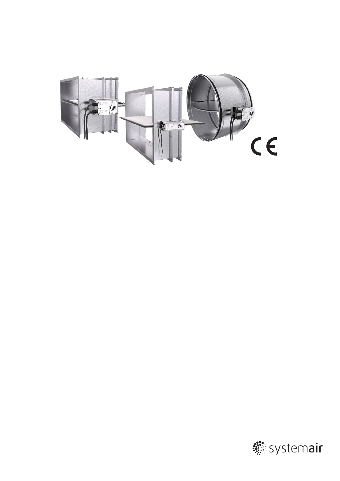
SMOKE CONTROL DAMPERS
Round DKIR1 and Rectangular DKIS1
ORIGINAL INSTALLATION, OPERATION AND MAINTENANCE MANUAL
EVERY SMOKE DAMPER NEEDS TO BE INSTALLED IN ACCORDANCE WITH THIS MANUAL!
Page 2
2 / 8 | DKIR1 & DKIS1 | 202010
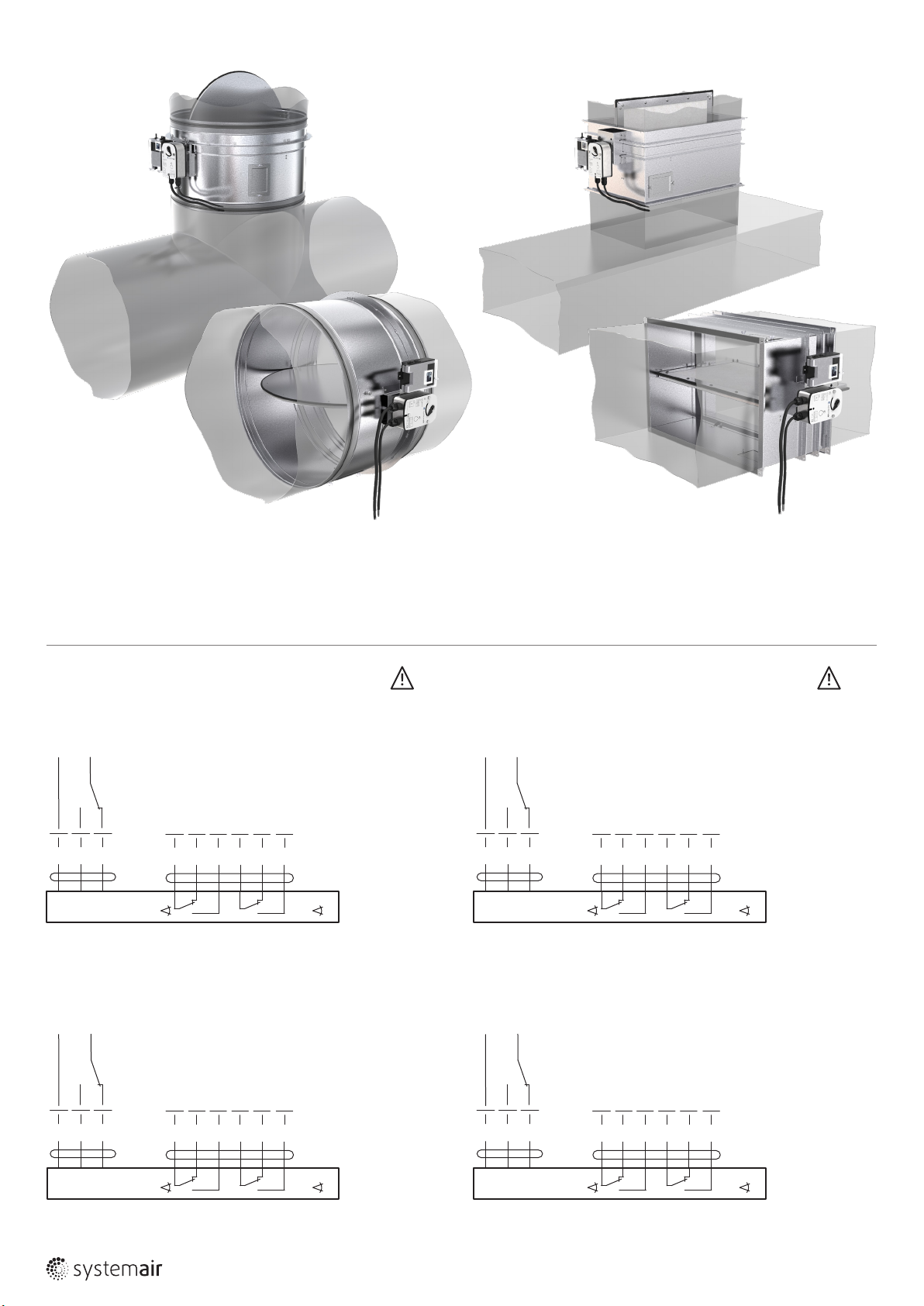
Fig. 1: Installatin of the round smoke damper DKIR1 onto and into
the duct running through the vertical supporting construction
(ved - see the re resistivity on the page 3)
NOTE: Installation onto the duct - distance between lower edge of the open blade
and bottom wall of the duct must be more than 100 mm.
NOTES:
• Caution: Main power supply voltage!
AC 230 V
N
1
• Parallel connection of several actuators possible.
Power consumption and switching thresholds must be observed!
• When power supply is connected to wires 1 and 3,
actuator drives to position OPEN.
L1
• When power supply is connected to wires 1 and 2,
actuator drives to position CLOSED.
• Circuit switch between wires 2 and 3 is not part
of the damper delivery.
2 3
S1 S2 S3 S4 S5 S6
<3°
<87°
Fig. 2: Installatin of the rectangular smoke damper DKIS1 onto and
into the duct running through the vertical supporting construction
(ved - see the re resistivity on the page 3)
NOTE: Installation onto the duct - distance between lower edge of the open blade
and bottom wall of the duct must be more than 100 mm.
NOTES:
• Supply via safety isolation transformer
AC 230 V
N
1
• Parallel connection of several actuators possible.
Power consumption and switching thresholds must be observed!
• When power supply is connected to wires 1 and 3,
actuator drives to position OPEN.
L1
• When power supply is connected to wires 1 and 2,
actuator drives to position CLOSED.
• Circuit switch between wires 2 and 3 is not part
of the damper delivery.
2 3
S1 S2 S3 S4 S5 S6
<3°
<87°
Fig. 3: Connection of the actuator BELIMO BLE 230 Fig. 4: Connection of the actuator BELIMO BE 230-12
AC/DC 24 V
⊥ ~
+
–
NOTES:
• When power supply is connected to wires 1 and 3,
actuator drives to position OPEN.
• When power supply is connected to wires 1 and 2,
actuator drives to position CLOSED.
• Circuit switch between wires 2 and 3 is not part
of the damper delivery.
AC/DC 24 V
⊥ ~
+
–
NOTES:
• When power supply is connected to wires 1 and 3,
actuator drives to position OPEN.
• When power supply is connected to wires 1 and 2,
actuator drives to position CLOSED.
• Circuit switch between wires 2 and 3 is not part
of the damper delivery.
1
2 3
S1 S2 S3 S4 S5 S6
<3°
<87°
1
2 3
S1 S2 S3 S4 S5 S6
<3°
<87°
Fig. 5: Connection of the actuator BELIMO BLE 24 Fig. 6: Connection of the actuator BELIMO BE 24-12-ST
Page 3
202010 | DKIR1 & DKIS1 | 3 / 8
AC 230 V
Displays
LED
yellow
yellow
green
green
yellow
green
yellow
BKNE230-24
1
2
3
4
Nothing must
be assigned
to terminals
1 to 5
The device contains no
parts which can be
replaced or repaired by
the user.
5
a
6
7
M
Status
ashing light
steady light
ashing light
steady light
or
frequency
2-wire conductor
to BKSE24-6
b
BE(G)24-ST, BE24-12-ST
Function
damper moving to OPEN
damper open
damper moving to CLOSED
damper closed
faultashing at double
power failuredark+green
w1098402
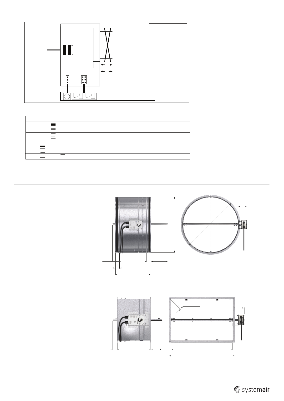
Fig. 7: Connection and display of the supply and communication unit BKNE230-24
Introduction
Instructions for installation, operation
and control refers to the smoke dampers
(hereafter dampers) circular DKIR1
and rectangular DKIS1, the products
of Systemair. It contains basic information
and recommendations regarding the
installation, use and inspections that need
to be followed to ensure proper
and smooth operation of the dampers.
R
2
Resistance class E
S500C
AA single is valid for all nominal
10000
120 (ved i ↔ o)
600
dimensions of round dampers (see Fig. 8)
and for nominal dimensions
of rectangular dampers where
W > 1200 mm (see Fig. 10).
Resistance class E
S1500C
AA single is valid only for
10000
120 (ved i ↔ o)
600
rectangular dampers with nominal
dimensions H × W from 200 × 200
up to 1200 × 800 mm (see Fig. 9).
R
1
45
45
L=400
Fig. 8: Dimensions of the round smoke damper
W
1
øD
øDN+45
8,8×11,8
W
1
R
1
L = 325
R
2
W×H
(W+40)×(H+40)
Fig. 9: Dimensions of the rectangular smoke damper for nominal dimensions
W × H = 200 × 200 up to 1200 × 800 mm
NOTE: These smoke dampers have anges width 20 mm.
Page 4

4 / 8 | DKIR1 & DKIS1 | 202010
8,8×11,8
R
L=360
1
R
2
W×H
(W+80)×(H+80)
W
1
Fig. 10: Dimensions of the rectangular smoke damper with W > 1200 mm up to 1500 × 800 mm
NOTE: These smoke dampers have anges width 40 mm.
Warnings
Some damper parts can have sharp edges – therefore it
is necessary to use gloves during damper installation and
manipulation.
In order to prevent an electric injury, re or any other damage
which could result from incorrect damper usage and operation,
it is important to:
1. Install the damper in accordance with the installation manual
and by a properly trained employee.
2. Execute the damper inspection in accordance with this
installation, operation and maintenance manual.
3. Before you can install the smoke damper, it‘s functionality
must be checked according to chapter 3 Check of the
functionality.
This procedure prevents installation of a damper that has
• Distance between dampers and building structures, distribution
technology and ventilation equipment must be large enough
for reliable performance of the installation, functional testing,
inspection and repair.
• The distance between the dampers must be at least 200 mm
according to EN 1366-10.
• The distance between dampers and the wall or ceiling must be
at least 200 mm according to EN 1366-10.
• The gap between the damper and the selfstanding grill (when
installed) must be at least 200 mm according to EN 1366-10.
Otherwise the damper must be tested together with the grill.
• The smoke dampers must be installed with horizontal blade axis.
• Before the installation of the smoke damper, it‘s functionality
must be tested according to the chapter 3 Check of the
functionality.
been damaged during transportation or handling.
Do not install functionless re dampers!
DO NOT INSTALL NONFUNCTIONAL SMOKE DAMPERS!
Operating conditions
Smoke dampers are part of the Smoke and Heat Exhaust
Ventilation System (SHEVS). Functionality of the smoke damper
is following. In case of re damper:
• opens and removes the heat and smoke through a special fan
from the re compartment affected by re or
• closes and prevents the spread of smoke and heat in the re
compartment unaffected by re.
All smoke dampers have electric actuator as standard. They are
designed to be installed in the SHEVS ducts in locations that are
protected from weather.
Systemair smoke dampers are passive in terms of noise. There is
increased noise only when closing or opening the damper in case
of inspection or re (and it takes less than 60 seconds).
1 Installation
The installation must be done as follows:
• Duct connected to the damper must be supported or
suspended so that the damper do not bear its weight.
The damper must not bear any part of the supporting
construction. This could lead to damage and subsequent failure
of the damper.
• Actuator can be on either side of the supporting construction,
but it must be placed so that it is easy to access for inspection
and repairs.
• Changes of smoke damper functionality, caused by transport
or installation, aren´t reclaimable after the installation
(deformations, damages, mechanical damage of the sealing
material, foreign objects which can constrain the blade, wrong
handling of the activating mechanism etc.)
• Before connection of the smoke damper into the ductwork,
smoke damper‘s functionality must be checked again
(according to chapter 3 Check of the functionality).
IT IS NOT POSSIBLE TO CLAIM FAULTY FUNCTIONALITY CAUSED
BY PRODUCTION, TRANSPORTATION OR INSTALLATION AFTER
CONNECTING THE DUCTS TO THE SMOKE DAMPER!
During installation, it is necessary to protect the damper
mechanism and its interior against dirt. The blade must be
in the closed position. It is necessary to avoid deformation
of the damper. Installation and setup of the dampers is always
determined by SHEVS project plans that must comply with the
applicable regulations.
The smoke dampers DKIR1 must be installed according to Fig. 1,
the smoke dampers DKIS1 must be installed according to Fig. 2.
After damper installing into the SHEVS duct it is necessary
to connect electrical installation that must be done only by
authorized persons – connection has to be done according to
Fig. 3 - 7. The actuators have two microswitches indicating
the open and closed positions of the blade - see Fig. 3 - 6.
Setup, install, repair, overhaul and inspections of the dampers
must be done only by the manufacturer or by the personnel
Page 5

202010 | DKIR1 & DKIS1 | 5 / 8
trained by the manufacturer.
Before putting dampers into service after installation
(and in subsequent periodic inspections) visual inspection
and functional test must be conducted. After the visual inspection
and functional test a record must be made into operational diary
(page 6).
2 Operating and Maintenance
2.1 The damper operation
After installation, the damper must be set up into the
operating position - closed. By connecting a power source
to activate the actuator the blade shall move. Respective
switching power supply achieves entry into the operating
position - closed.
2.2 Maintenance
Systemair smoke dampers are maintenance free.
3 Check of the functionality
Switching the supply phase according to Figure 3 - 7 damper
switch to the „open“:
• The blade must come to the fully open position and must
remain there detented.
• After reaching the end position of the blade the appropriate
signaling circuit must switch on.
Switching the supply phase according to Figure 3 - 7 switch
damper to the „closed“:
• The blade must come up to the fully closed position
and remain there detented.
• After reaching the end position of the blade the appropriate
signaling circuit must switch on.
Now the damper is in standby mode, so it must rest for normal
operation.
4 Inspection of the damper
Each damper should be inspected after installation and every
12 months using following steps:
1. Identication of damper
2. Date of inspection
3. Check of the electrical connection of the activation
mechanism
4. Check of the the electrical connection of the end switches
5. Check of the damper for cleanliness and eventually treatment
(where necessary)
6. Removing of the cover of the inspection lid.
7. Check of the inspection lid, cover tightness and eventually
correction and record (where applicable)
8. Check of the blade and sealings, and eventually correction
and record (where applicable)
9. Check of the safety damper closure - details see Chap. 3
10. Check of the damper functionality (details see Chap. 3)
opening and closing by the control system, tracking
the physical behavior of the dampers and signalization
of the end positions, and eventually correction and record
(where applicable)
11. Closing of the cover of the inspection lid.
12. Set up into the operating position - see Chap. 2.1
13. Record into operational diary (page 6) with name
and signature of the checker.
The damper is part of the SHEVS. Therefore the system must
be checked as specied in its operational and maintenance
requirements.
5 Warranty conditions:
1. IMOS-Systemair a.s. provides warranty for all its DKI smoke
dampers. The warranty period is 24 months, starting on
the date of product shipment, by an exceptional agreement
this period can be up to 30 months, starting on the date of
shipment.
2. The product is tested in the production factory before the
shipment. The producer guarantees that the product features
shall be in accordance with the related technical standards
during the whole warranty period, assuming that the
customer uses it in a way that complies with the Operation
manual. If, in spite of this, any unpredictable production
defects occur, the producer shall secure their removal
without charge.
3. The customer may apply for the warranty service only in
written form including serial number of the claimed damper.
4. The warranty does not apply to defects caused by
unprofessional handling, incorrect mounting, mechanical
damage or not following the instructions stated in the
Operation manual.
5. The warranty period shall be prolonged for the same period of
time which has elapsed between the date when the customer
lodged the claim for warranty service and the date when the
repair was carried out.
6. The repair shall be carried out at the customer’s premises and
the producer shall bear all the costs which are necessarily
needed for the repair.
7. In case no defects applicable for warranty are identied, the
costs associated with the arrival of the service technician will
be handled by the customer who led the warranty repair
claim.
8. Before you can install the smoke damper, it‘s functionality
must be tested according to the chapter 3 Check of the
functionality.
DO NOT INSTALL NONFUNCTIONAL SMOKE DAMPERS!
Changes of smoke damper functionality, caused by transport
or installation, aren´t reclaimable after the installation
(deformations, damages, mechanical damage of the sealing
material, foreign objects which can constrain the blade, wrong
handling of the activating mechanism etc.)
9. Before you can connect the smoke damper into the ductwork,
smoke damper‘s functionality must be checked again
(according to chapter 3 Check of the functionality).
IT IS NOT POSSIBLE TO CLAIM FAULTY FUNCTIONALITY CAUSED
BY PRODUCTION, TRANSPORTATION OR INSTALLATION AFTER
CONNECTING THE DUCTS TO THE SMOKE DAMPER!
The dampers are transported in covered means of transport,
on pallets or in boxes. When handling during transportation
and storage, the dampers must be protected against damage
and weather conditions and the damper blades must be in
the closed position. These products must be stored in a closed
and dry area where the temperature is kept within the range
of -20 °C to +50 °C.
Page 6

6 / 8 | DKIR1 & DKIS1 | 202010
OPERATING DIARY
Activation of the damper
Date
Periodic damper inspection - at least once in 12 months
Date
Description of found defects and date of the following inspection
after deciencies elimination
Description of found defects and date of the following inspection
after deciencies elimination
Inspection technician‘s signature
Inspection technician‘s signature
Page 7

Periodic damper inspections - at least once in 12 months
202010 | DKIR1 & DKIS1 | 7 / 8
Date
Description of found defects and date of the following inspection
after deciencies elimination
Inspection technician‘s signature
Page 8

202010 | DKIR1 & DKIS1 | 8 / 8
12 1396
Systemair Production a.s.
Hlavná 371, 900 43 Kalinkovo, Slovakia
1396-CPD-0058
EN 12101-8
Smoke damper:
round DKIR1-DN, rectangular DKIS1-WxH
Operational reliability:
- cycling 10 200 cycles Pass
Fire resistance:
E
120(ved i↔o)S500C
600
E
120(ved i↔o)S1500C
600
AAsingle or
10000
AAsingle
10000
- maintenance of the cross section (under E)
- integrity E 600°C
- smoke leakage S 500 Pa and 1500 Pa
- mechanical stability (under E)
- cross section (under E)
Durability of operational reliability: Pass
- open and closing cycle
Smoke damper identication
Construction site
Placement
Room No.
ID No.
Label
Warranty service
Date of claim
submission
Date of the repair Description of the repair
Signalization
Service ofcer
(signature & stamp)
 Loading...