

SystemAir DVS series, DVN series, DVSI series, DVNI series, DHS series Installation And Operating Instructions Manual
...Page 1
Document in original language | · 005
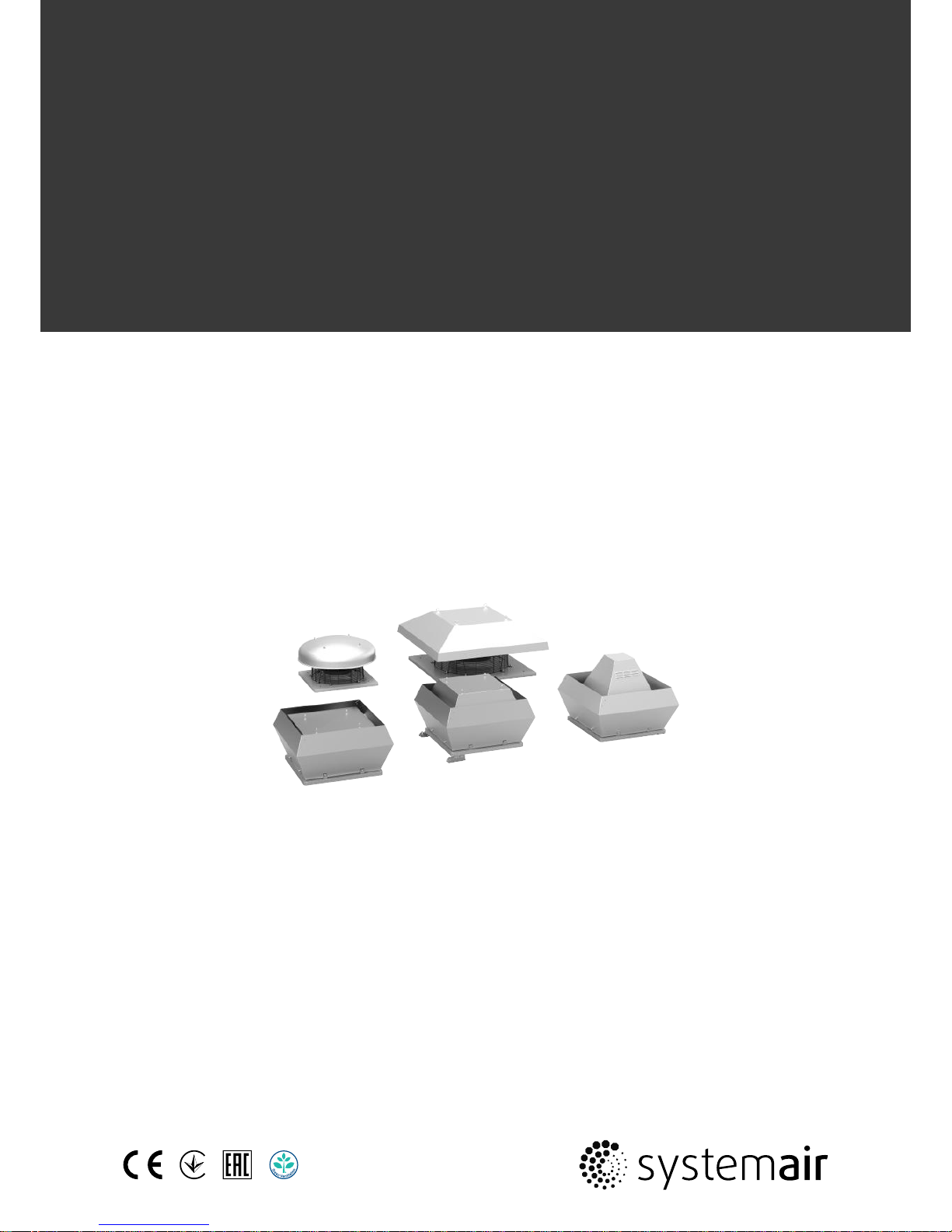
Roof fans
DVN(I), DVS(I), DVC(I), DHS
Installation and Operating Instructions
GB
Page 2

| 005
© Copyright Systemair AB
All rights reserved
E&OE
Systemair AB reserves the rights to alter their products without notice.
This also applies to products already ordered, as long as it does not affect the previously agreed specifications.
Page 3

| 005
Contents
1 General information ........... . ..... . ...... ...... ...... .....1
1.1 Notice symbols . . ..... . ...... ...... ...... . ..... . .....1
1.1.1 Instruction symbols. . ...... ...... ...... .1
2 Important safety information ...... . ...... ...... ...... ....1
2.1 Personnel ...... ...... ...... . ...... ...... ...... ...... . .1
2.2 Personal protective equipment.. ...... ...... . ...2
2.3 5 rules of electrical safety ...... ...... . ..... . .....2
3 Warranty... ...... . ..... . ...... ...... ...... ...... . ..... . ...... ..2
4 Delivery, transport, storage .... . ...... ...... ...... ...... . .2
5 Description ... . ..... . ...... ...... ...... ...... . ..... . ...... .....4
5.1 Description DVN/DVNI . ...... ...... . ...... ...... ...4
5.2 Description DVS/DVSI ... ...... ...... . ..... . ...... ..5
5.3 Description DVC/DVCI..... ...... . ..... . ...... ...... 6
5.4 Description DHS ... . ...... ...... ...... ...... . ...... ..8
5.5 Fan and motor data .. ...... . ..... . ...... ...... .....8
5.6 Intended use .... . ..... . ...... ...... ...... . ..... . .....8
6 Name plate and type key ..... ...... . ...... ...... ...... ....9
7 Accessories.... . ...... ...... ...... ...... . ...... ...... ...... .. 10
8 Installation.. ...... . ..... . ...... ...... ...... ...... . ..... . .....11
8.1 Installation of the ventilation
system ...... ...... ...... . ...... ...... ...... ...... . .. 11
8.1.1 DVC-P pressure tube . ...... ...... .... 12
8.2 Assembly/Disassembly impeller —
Internal rotor motor ..... . ...... ...... ...... ...... 12
8.3 Assembly tilting device (FTG).... ...... ...... .. 14
9 Electrical connection .... ...... . ...... ...... ...... ...... . .. 14
9.1 Electrical connection accessories ...... . ..... . 15
9.2 Protecting the motor.... ...... ...... ...... . ...... 15
9.3 Variable-speed fans ...... . ..... . ...... ...... ..... 16
10 Commissioning ..... ...... ...... . ..... . ...... ...... ...... ... 16
11 Operation . . ...... ...... ...... . ..... . ...... ...... ...... ...... . 17
12 Troubleshooting/maintenance/repair .... . ..... . .....17
12.1 Troubleshooting.. . ..... . ...... ...... ...... ...... . . 17
12.2 Maintenance.... . ...... ...... ...... . ..... . ...... ... 18
12.3 Spare parts .... ...... ...... . ...... ...... ...... ...... 19
13 Cleaning... ...... . ..... . ...... ...... ...... ...... . ...... ...... . 19
14 Deinstallation/dismantling. ...... ...... . ..... . ...... .....19
15 Disposal ..... ...... ...... ...... . ..... . ...... ...... ...... ...... 19
16 EU Declaration of conformity — Roof
fans ..... ...... . ..... . ...... ...... ...... . ..... . ...... ...... .... 20
17 EU Declaration of conformity — Thermo
fans ..... ...... . ..... . ...... ...... ...... . ..... . ...... ...... .... 20
18 Commissioning Report.. ...... . ...... ...... ...... ...... . .. 21
Page 4

Page 5
General information |
1
1 General information
1.1 Notice symbols
Danger
Direct hazard
Failure to comply with this warning will lead
directly to death or to serious injury.
Caution
Hazard with a low risk
Failure to comply with this warning may lead to
moderate injuries.
Warning
Potential hazard
Failure to comply with this warning may lead to
death or serious injury.
Important
Hazard with risk of damage to objects
Failure to comply with this warning will lead to
damage to objects.
Note:
Useful information and instructions
1.1.1 Instruction symbols
Instruction
Instruction with xed sequence
♦ Carry out this action
1. Carry out this action
3. (if applicable, further actions)
♦ (if applicable, further actions)
2. Carry out this action
2 Important safety information
Planners, plant builders and operators are responsible for the proper assembly and intended use.
♦ Read the operating instructions completely and carefully.
♦ Keep the operating instructions and other valid documents, such as the circuit diagram or motor instructions, with
the fan. They must always be available at the place of use.
♦ Observe and respect local conditions, regulations and laws.
♦ Abide by the system-related conditions and requirements of the system manufacturer or plant constructor.
♦ Safety elements may not be dismantled, circumvented or deactivated.
♦ Only use the fan in a awless condition.
♦ Provide generally prescribed electrical and mechanical protective devices.
♦ During installation, electrical connection, commissioning, troubleshooting, and maintenance, secure the location and
premises against unauthorised access.
♦ Do not circumvent any safety components or put them out of action.
♦ Keep all the warning signs on the fan complete and in a legible condition.
♦ The device is not to be used by persons (including children) with reduced physical, sensory or mental capabilities, or
lack of experience and knowledge, unless they have been given supervision or instruction.
♦ Do not allow children to play with the device.
2.1 Personnel
The fan may only be used by qualified, instructed and trained personnel. The persons must know the relevant safety directives in order to recognise and to avoid risks. The individual activities and qualifications can be found in Table 1 Qual-
ifications, page 2.
| 005
Page 6
2
|
Warranty
Table 1 Qualifications
Activities
Qualifications
Storage, operation, transport, cleaning, disposal Trained personnel (see following note)
Electrical connection, commissioning, electrical
disconnection
Electrical expert or matching qualification
Installation, disassembly Fitter or matching qualification
Maintenance
Electrical expert or matching
qualification
Fitter or matching
qualification
Repair
Electrical expert or matching
qualification
Fitter or matching
qualification
Smoke extraction fans and EX fans only by agreement with
Systemair.
Note:
The operator is responsible for ensuring that personnel are instructed and have understood the contents of
the operating instructions. If something is unclear, please contact Systemair or its representative.
2.2 Personal protective equipment
♦ Wear protective equipment during all work in the vicinity of the fan.
• protective working clothes
• protective working shoes
• protective working gloves
• helmet
• goggles
• hearing protection
2.3 5 rules of electrical safety
1. Disconnect (disconnection of
the electrical system from
live components at all
terminals)
2. Prevent reactivation
3. Test absence of voltage
4. Ground and short-circuit
5. Cover or restrict adjacent live parts
3 Warranty
For the assertion of warranty claims, the products must be correctly connected and operated, and used in accordance
with the data sheets. Further prerequisites are a completed maintenance plan with no gaps and a commissioning report. Systemair will require these in the case of a warranty claim. The commissioning report is a component of this
document. The maintenance plan must be created by the operator, see section 12.2 Maintenance, page 18.
4 Delivery, transport, storage
Safety information
Warning: Risk from rotating fan blades
♦ Prevent access by unauthorised persons by safety personnel or access protection.
Warning: Suspended loads
♦ Wear protective equipment during all work in the vicinity of the fan, details see 2.2 Personal protective equipment,
page 2.
♦ Do not walk under suspended loads.
♦ Make sure that there is nobody under a suspended load.
Delivery
Each fan leaves our plant in an electrically and mechanically proper condition. We recommend transporting the fan to
the installation site in the original packaging.
| 005
Page 7
Delivery, transport, storage |
3
Checking delivery
♦ Check the packaging and the fan for transport damage. Any findings should be noted on the cargo manifest.
♦ Check completeness of the delivery.
Unpacking
Warning
When opening the transport packaging, there is a risk of damage from sharp edges, nails, staples,
splinters etc.
♦ Unpack the fan carefully.
♦ Check the fan for obvious transport damage.
♦ Only remove the packaging shortly before assembly.
♦ Wear protective equipment during all work in the vicinity of the fan, details see 2.2 Personal protective
equipment, page 2.
Transport
Safety information
Warning: Electrical or mechanical hazards due to fire, moisture, short circuit or malfunction.
♦ Never transport the fan by the connecting wire, terminal box, impeller, protection grille, inlet cone or silencer.
♦ In open transport, please make sure that no water can penetrate into the motor or other sensitive parts.
♦ We recommend transporting the fan to the installation site in the original packaging.
Caution: If transported without care during loading and unloading, the fan may be damaged.
♦ Load and unload the fan carefully.
♦ Use hoisting equipment that is suitable for the weight to be hoisted.
♦ Observe the transportation arrows on the packaging.
♦ Use the fan packaging exclusively as transport protection and not as a lifting aid.
Storage
♦ Store the fan in the original packaging in a dry, dust-free location protected against weather.
♦ Avoid the effects of extreme heat or cold.
Important
Hazard due to loss of function of the motor bearing
♦ Avoid storing for too long (recommendation: max. 1 year).
♦ Check that the motor bearing functions properly before installation.
| 005
Page 8

4
|
Description
5 Description
Roof fans equipped with an EC motor
The fans are driven by EC motors. These motors are delivered with a pre-wired potentiometer (0–10 V) that allows you
to easily find the required working point of the fan. All motors are suitable for 50/60 Hz. The input voltage for singlephase units can vary between 200 and 277 V for three phase units between 380 and 480 V. All models have one potential-free terminal for error message.
Roof fans equipped with an AC motor
For information on speed regulation options, see 6 Name plate and type key, page 9.
5.1 Description DVN/DVNI
Table 2 Dimensions DVN
E
D
C
B
A
Ri K
H
H
G
F
M20x1,5
J
I(4x)
[mm]
A B C D E F G H I J K
355—400 720 618 600 390 438 595 450 200
12(4x)
6xM8 18.5
450—500 900 730 675 465 438 665 535 237
12(4x)
6xM8 18.5
560—630 1150 955 900 560 605 939 750 293
14(4x)
8xM8 0
710 1350 1178 936 660 674 1035 840 320
14(4x)
8xM8 0
800—900 1690
-
1180 830 872 1255 1050 433
14(4x)
8xM8 0
Table 3 Dimensions DVNI
[mm]
A B C D E F G H I J K
355—400 874 648 600 439 438 595 450 200
12(4x)
6xM8 18.5
450—500 970 730 675 479 438 665 535 237
12(4x)
6xM8 18.5
560—630 1315 1035 900 600 605 939 750 293
14(4x)
8xM8 0
710 1483 1165 936 729 674 1035 840 320
14(4x)
8xM8 0
800—900 1590
-
1180 830 872 1255 1050 433
14(4x)
8M8 0
| 005
Page 9
Description
|
5
5.2 Description DVS/DVSI
Table 4 Dimensions DVS
H
M20x1,5
I
K
F
E
C
B
A
[mm]
A B C E F H K I
190–225 370 320 175 335 245 6xM6 213
10(4x)
310–311 560 470 330 435 330 6xM8 285
10(4x)
355–400 723 623 390 595 450 6xM8 438
12(4x)
450–500 900 730 465 665 535 6xM8 438
12(4x)
560–630 1150 960 565 939 750 8xM8 605
14(4x)
710 1350 1185 660 1035 840 8xM8 674
14(4x)
Table 5 Dimensions DVSI
[mm]
A B C E F H K I
190–225 498 438 210 335 245 6xM6 213
10(4x)
310–311 695 584 370 435 330 6xM8 285
10(4x)
355–400 877 745 440 595 450 6xM8 438
12(4x)
450–500 970 825 479 665 535 6xM8 438
12(4x)
560–630 1315 1130 600 939 750 8xM8 605
14(4x)
710 1483 1185 729 1035 840 8xM8 674
14(4x)
| 005
Page 10

6
|
Description
5.3 Description DVC/DVCI
S-Version:
The DVC-S version can be stepless controlled via a 0-10 V signal. The operating point can be directly adjusted with the
integrated potentiometer (10 K ohms).
POC-Version
The DVC-POC version has integrated pressure sensors and temperature sensor for outdoor temperature compensation.
The electronics can be programmed for a constant pressure operation with or without outdoor temperature compensation (The factory setting is with outdoor temperature compensation). For any details of the controller, please see the
separate attached controller manual.
P-Version:
The DVC-P version has integrated pressure sensors and the electronic is programmed for a constant pressure operation.
For any details of the controller, please see the separate attached controller manual.
This version can also be ordered as CAV (constant air volume).
Table 6 K-factor (measured values) DVC-P
315–P EC 103 450–P EC 245 560–P EC 298
355–P EC 143 450–K-P EC 253 630–P EC 498
400–P EC 207 500–P EC 365 710–P EC 628
Table 7 Dimensions DVC-S
H
M20x1,5
I
K
F
E
C
B
A
[mm]
A B C E F H K I
190–225 370 320 175 335 245 6xM6 213
10(4x)
315 560 470 330 435 330 6xM8 285
10(4x)
355–400 723 623 390 595 450 6xM8 438
12(4x)
450–500 900 730 465 665 535 6xM8 438
12(4x)
560–630 1150 960 565 939 750 8xM8 605
14(4x)
Table 8 Dimensions DVCI-S
[mm]
A B C E F H K I
190–225 498 438 210 335 245 6xM6 213
10(4x)
315 695 584 370 435 330 6xM8 285
10(4x)
355–400 874 648 439 595 450 6xM8 438
12(4x)
450–500 970 730 479 665 535 6xM8 438
12(4x)
560–630 1315 1130 600 939 750 8xM8 605
14(4x)
| 005
Page 11

Description
|
7
Table 9 Dimensions DVC-P/DVC-POC
H
M20x1,5
I
K
F
E
C
D
B
A
[mm]
A B C D E F H K I
190–225 370 320 175
-
335 245 6xM6 213
10 (4x)
315 560 470 330 378 435 330 6xM8 285
10 (4x)
355–400 723 623 390 438 595 450 6xM8 438
12 (4x)
450–500 900 730 465 515 665 535 6xM8 438
12 (4x)
560–630 1150 960 565 585 939 750 8xM8 605
14(4x)
Table 10 Dimensions DVCI-P/DVCI-POC
[mm]
A B C D E F H K I
225 498 438 210
-
335 245 6xM6 213
10(4x)
315 690 583 369 415 435 330 6xM6 285
10(4x)
355–400 877 745 440 439 595 450 6xM8 438
12(4x)
450–500 970 825 479 516 665 535 6xM8 438
12(4x)
560–630 1315 1135 600 619 939 750 8xM8 605
14(4x)
| 005
Page 12

8
|
Description
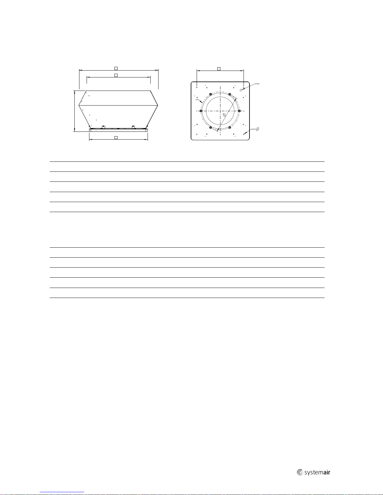
5.4 Description DHS
The fans are equipped with AC motors. For information on speed regulation options, see 6 Name plate and type key,
page 9.
Table 11 Dimensions DHS
size 190 to 500 –> round cap
Ø A
Ø E
C
H
F
M20x1,5
Ø I(4x)
Ø K
size 560 to 710 –> squared cap
A
C
E
F
M20x1,5
Ø I(4x)
H
Ø K
[mm]
A C E F H K I
190–225 417 150 335 245 6xM6 213
10(4x)
310–315 540 250 435 330 6xM8 285
10(4x)
355–400 720 330 595 450 6xM8 438
12(4x)
450–500 830 490 665 535 6xM8 438
12(4x)
560–630 1100 535 939 750 8xM8 605
14(4x)
710 1282 580 1035 840 8xM8 674
14(4x)
5.5 Fan and motor data
• Max. temperature of transported air, max. ambient temperature, sound pressure –> see data sheet, available in our
online catalogue.
• Voltage, current, enclosure class, weight –> see name plate
• The motor data can be found on the name plate of the motor, or in the technical documents of the motor
manufacturer.
5.6 Intended use
All roof fans
• The fans are intended for installation in ventilation systems. They can be installed both in duct systems and also
with free suction via an inlet cone and a suction-side contact protection grille. Systemair recommends a Back draft
damper (VKS) to avoid cold air intake at a standstill of the fan, see 7 Accessories, page 10.
• The maximum permissible operating data on the name plate apply for an air density of 1.2 kg/m³ (sea level) and
a max. air humidity of 80 %.
• The fans are exclusively intended for extract air applications.
DVN, DVNI
• The fan is suitable for conveying contaminated air
(dust, kitchen exhaust), with a density of 1.3 kg/m3
and a max. air humidity of 95 %.
DVS, DVSI, DVC, DVCI, DHS
• The fan is suitable for conveying clean air, with a
density of 1.3 kg/m3 and a max. air humidity of 95
%.
Incorrect use
Incorrect use refers mainly to using the fan in another way to that described. The following examples are incorrect
and hazardous:
• Conveying of explosive and combustible media
• Conveying of aggressive media
• Operation in an explosive atmosphere
• Operation without duct system or protection grille
• Operation with the air connections closed
| 005
Page 13

Name plate and type key |
9
6 Name plate and type key
1
2
3
4
5
6
8
7
400 V
1
Type designation
5
Enclosure class/fan impeller speed/weight
2
Voltage/current/frequency
6
Insulation class
3 Input power 7
Article number/production number/manufacturing date
4
Max. temperature of transported air
8
Certifications
Table 12 Type key
DVN 500
-
D4
Motor type
EC
Electronically commutated/1 phased or 3 phased
E2
2 poled/controllable by frequency converter/1 phased
E4
4 poled/controllable by frequency converter/1 phased
E6
6 poled/controllable by frequency converter/1 phased
DV
4 poled voltage controllable/3 phased
DS
6 poled voltage controllable/3 phased
EZ
2 poled voltage controllable/1 phased
EV
4 poled voltage controllable/1 phased
ES
6 poled voltage controllable/1 phased
D4
4 poled/controllable by frequency converter/3 phased
D6
6 poled/controllable by frequency converter/3 phased
Only at DVC
S
Controllable via a 0-10 V signal
P
Integrated pressure sensors
POC
Integrated pressure sensors and temperature sensor
Size
Fan type
DVN
Roof fan - vertical discharge - high temperature
DVNI
Roof fan - vertical discharge - high temperature - insulated
DVS
Roof fan - vertical discharge - standard
DVSI
Roof fan - vertical discharge - standard - insulated
DVC
Roof fan - vertical discharge - ec motor
DVCI
Roof fan - vertical discharge - ec motor - insulated
DHS
Roof fan - horizontal discharge - standard
| 005
Page 14

10
|
Accessories
7 Accessories
For details of the accessories, please check our online catalog or contact Systemair.
2
3
4
5
2
6
7
9
10
8
1a
1b
1c
1d
1d
Table 13 Accessories
1a DVN, DVNI Roof fan - vertical discharge - high temperature - (insulated)
1b DVS/DVSI Roof fan - vertical discharge - standard - (insulated)
1c
DVC/DVCI Roof fan - vertical discharge - ec motor - (insulated)
1d
DHS
Roof fan - horizontal discharge - standard
size 190 to 500 –> round cap
size 560 to 710 –> squared cap
2
VKS (ii) Back draft damper
7
FTG (iii) Tilting device
3
SSD (i)
Socket silencer
8 TDA
Adapter framework
4 ASK
Inflow box SSD
9
VKM (ii)
Back draft damper (motor
driven)
5 ASS
Flexible connection
10
FDS (i)
Flat roof socket
6 ASF
Inlet flange
Note:
i. Size 190–450: If the degree of inclination is higher than 15°, a SSS (Slanting socket silencer) or a SDS
(Slanting roof socket) has to be used.
Size 499–630: If the degree of inclination is higher than 10°, a SSS (Slanting socket silencer) or a SDS
(Slanting roof socket) has to be used.
ii. Do not install a VKS (self-actuating back draft damper) for roof fans (e.g. P version, POC version) which
are controlled by sensors in the duct system. In this case, you must use a VKM (motor-driven back draft
damper).
iii.See chapter 8.3 Assembly tilting device (FTG), page 14
| 005
Page 15

Installation |
11
8 Installation
Safety information
Warning: Danger from falling fan or fan parts.
♦ Check the surface before installation for load bearing capacity.
♦ Consider all static and dynamic loads when selecting hoisting equipment and fastening components.
General safety information
♦ Installation may only be carried out by adequately qualified persons, details see Table 1 Qualifications, page 2.
♦ Move the rotor of the fan by hand before you install it in order to check that it moves freely.
♦ Provide contact and intake protection and ensure safety distances according to DIN EN ISO13857 and DIN 24167-1.
♦ Prevent the possibility of foreign bodies being drawn in.
♦ To reduce transmission of vibration to the duct system, we recommend flexible connections from our accessory
range, see chapter Accessories.
Preconditions
♦ Ensure that the fan and all its components are
undamaged.
♦ Ensure that there is enough space to install the fan.
♦ Protect against dust and moisture when installing.
♦ Ensure that the information on the name plates (fan
and motor) matches up with the operating conditions.
♦ Fit the fans in such a way that there is sufficient
access for troubleshooting, maintenance and repair.
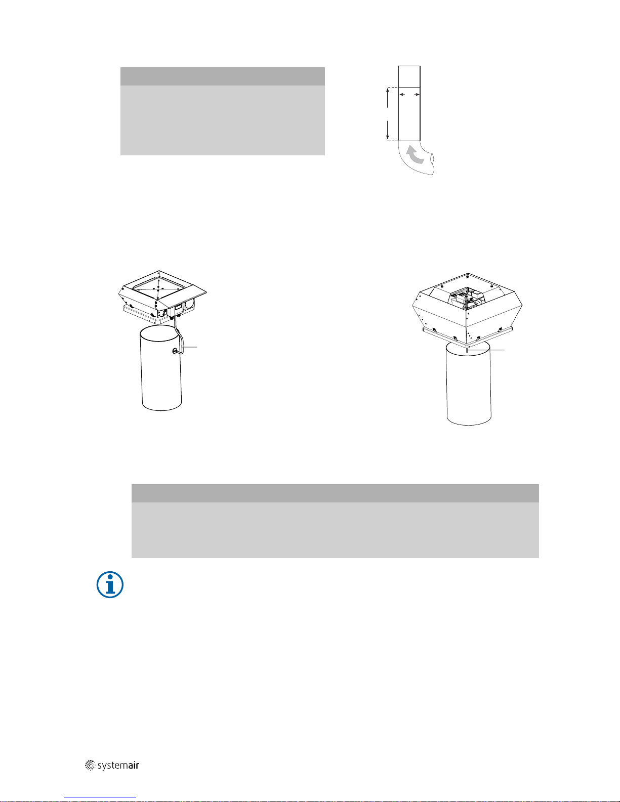
8.1 Installation of the ventilation system
Important
Leaking roof due to wrong installation.
♦ The roof seal (e.g. plastic or bitumen foil) has to be pulled
and fixed under the base plate of the roof fan, see below
picture.
Important
Leaking duct system.
♦ When installing the roof fan and accessories all mounting
surfaces have to be sealed air tight.
Important
Condensate formation due to thermal bridge.
If the fan and the accessories are insufficiently insulated,
condensation may form.
1. Check if the fan and accessories form a thermal bridge.
2. Insulate the fan and accessories sufficiently.
The below installation diagram is an example.
1
3
4
5
6
7
8
9
2
1 Base plate of the roof fan
6
VKS/VKM Back draft damper
2
SSS
Slanting socket silencer
7
Has to be realized on-site
3
Roof seal
e.g. plastic or bitumen foil
8 ASS
Flexible connection
4
Isolation
9
Duct system
5
Roof construction
| 005
Page 16
12
| Installation
Important
Damage to the bearings or other parts of the fan can
occur.
♦ Do not place a duct bend directly before or after
the fan!
♦ Ensure a smooth and constant air flow to the
device. Ensure a free exhaust. See .
• Rectangular duct system: D = Hydraulic diameter
• Round duct system: D = Nominal diameter
min.
2,5x Ø D
Ø D
8.1.1 DVC-P pressure tube
The following illustrations show the schematic installation of the pressure tubes.
Size
190–225
Size
315–710
A
B
A
Pressure tube
A
B
B Duct system
Controller input
-
Duct system
+
Atmosphere
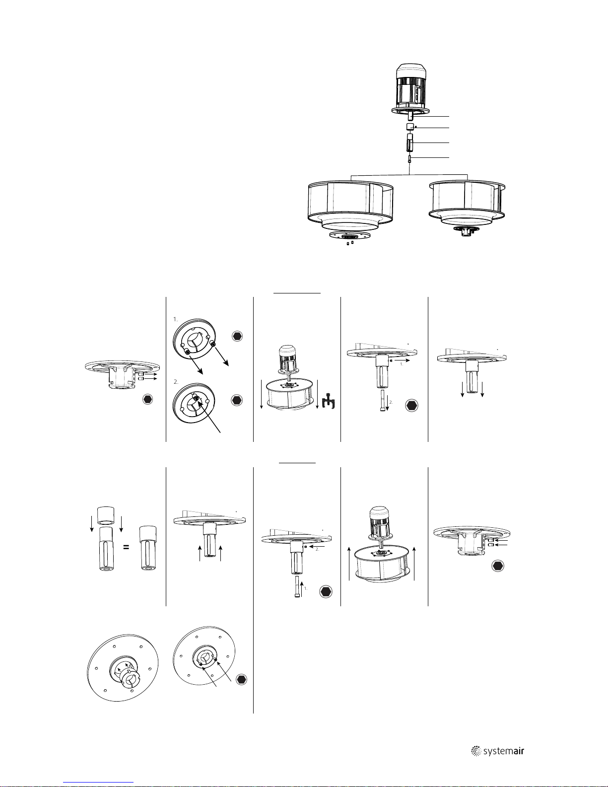
8.2 Assembly/Disassembly impeller — Internal rotor motor
If an external rotor motor is used, the motor and impeller can`t be seperated.
Important
Damage to the motor and impeller.
The ball bearing of the motor and the balanced impeller may be damaged by forceful impacts.
♦ Attach the impeller and/or the shaft extension to the shaft or the rotor without forceful impacts.
♦ Do not separate the impeller and the hub. They were balanced as one unit by Systemair.
Note:
The hub can be heated for easier assembly and disassembly, for example with a hot-air blower.
• Precondition for assembly: the wedge is in the intended groove.
• Tools: hexagon socket wrench and suitable tool for removal, torque wrench for the taper clamping bush.
| 005
Page 17
Installation |
13
1 Motor
1
2
3
4
5
6
6
87
2
Motor shaft
3
Sleeve (not available at every fan)
4
Shaft extension (not available at every fan)
5
Hexagon socket screw
6
Impeller
7
Steel hub
8
Aluminium hub
The hub is shown without impeller due to better lucidity.
Disassembly
1. Aluminium hub 1. Steel hub
2. 3. 4.
1.
2.
1.
2.
Assembly
1. 2. 3. 4.
5. Aluminium hub
=
Use screw locking
The set screw must
push on the wedge
of the shaft.
2.
1.
Use screw locking
5. Steel hub 6. Steel hub
Tighten the screws
slightly
Tighten the two
screws evenly with
the tightening torque
according to table
14.
| 005
Page 18
14
| Electrical connection
Table 14 Tightening torques for various types of bush
Type of bush
1008 1108 1210 1215 1310 1610 1615 2012 2517 3020
Tightening
torque [Nm]
5.7 5.7 20 20 20 20 20 31 49 92
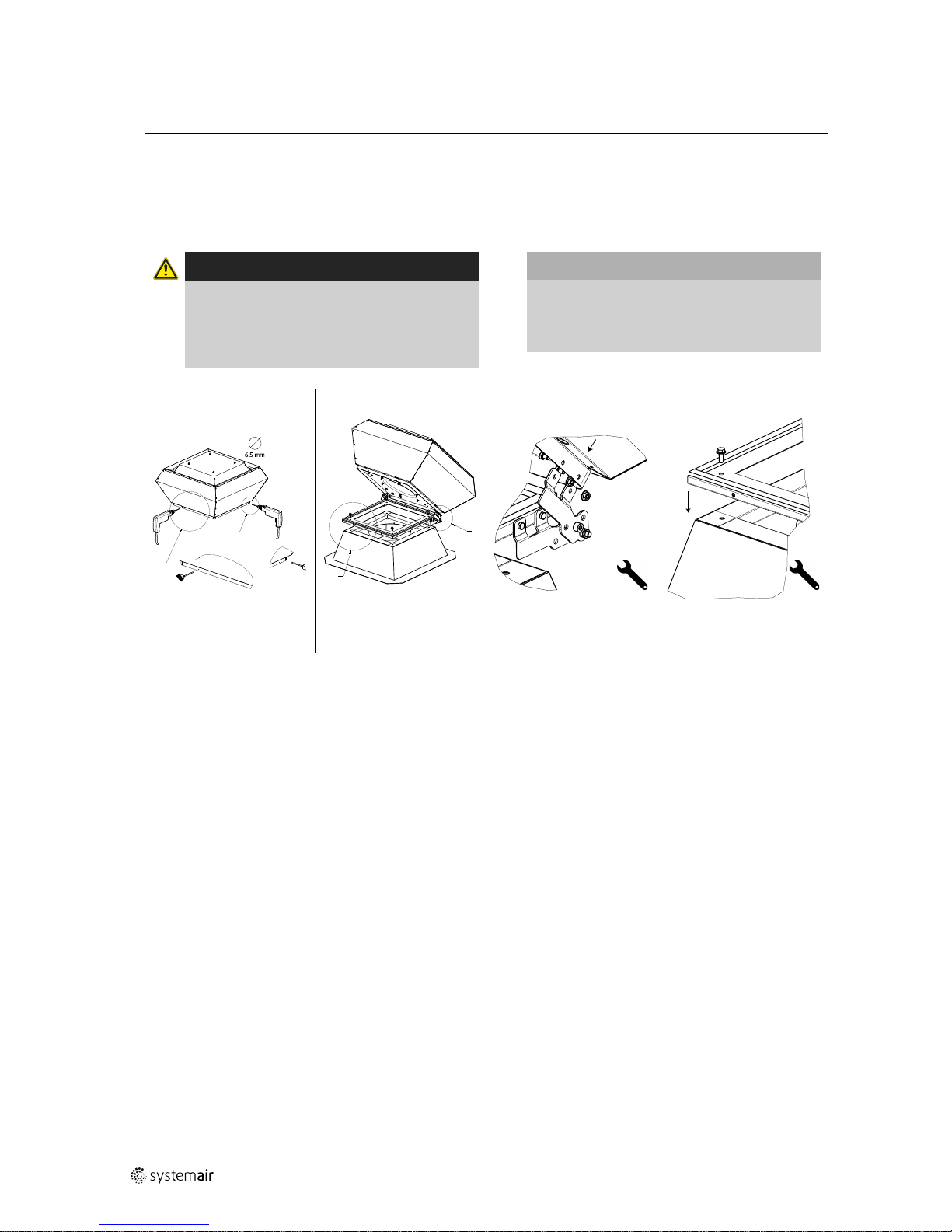
8.3 Assembly tilting device (FTG)
Warning
Danger of injury by tilting the fan during
installation.
♦ The tilting device must be secured in the
opened state by screws in the designated hole
against unintentional folding.
Important
Leaking duct system.
♦ When installing the roof fan and accessories,
all mounting surfaces have to be sealed air
tight.
1.
A
B
2. 3.
E
F
1:5
E
1:5
F
6.5 mm
A
B
9 Electrical connection
Safety information
Warning: Danger from electrical voltage!
♦ Observe the 5 rules of electrical safety, see 2.3 5 rules of electrical safety, page 2.
♦ Prevent the ingress of water into the connection box.
♦ Electrical connection may only be carried out by adequately qualified persons, details see Table 1 Qualifications, page
2.
Warning: Danger due to electrostatic influence on medical implants!
♦ Persons with medical implants should keep enough distance to the according devices.
| 005
Page 19
Electrical connection |
15
Connection
♦ Check if the data on the nameplate matches the
connection data.
♦ Complete the electrical connection according to the
circuit diagram.
♦ Fans with EC- motors must be switched on/off via the
control input.
♦ Use all of the locking screws.
♦ Connect the cable end in a dry environment.
♦ Insert the screws by hand to avoid damaging the
thread.
♦ Tighten all glands well in order to guarantee
protection class IP.
♦ Screw the lid of the terminal box/inspection switch
evenly tight.
♦ Install a circuit breaker in the permanent electrical
installation, with a contact opening of at least 3 mm
at each pole.
Protective grounding wire
The protective grounding must have a cross-section equal to or greater than that of the phase conductor.
Residual current circuit breaker
All-current-sensitive residual current circuit breakers are required for use in alternating-current systems with 50/60
Hz, in combination with electronic devices such as EC motors, frequency converters or uninterruptible power supplies
(UPS).
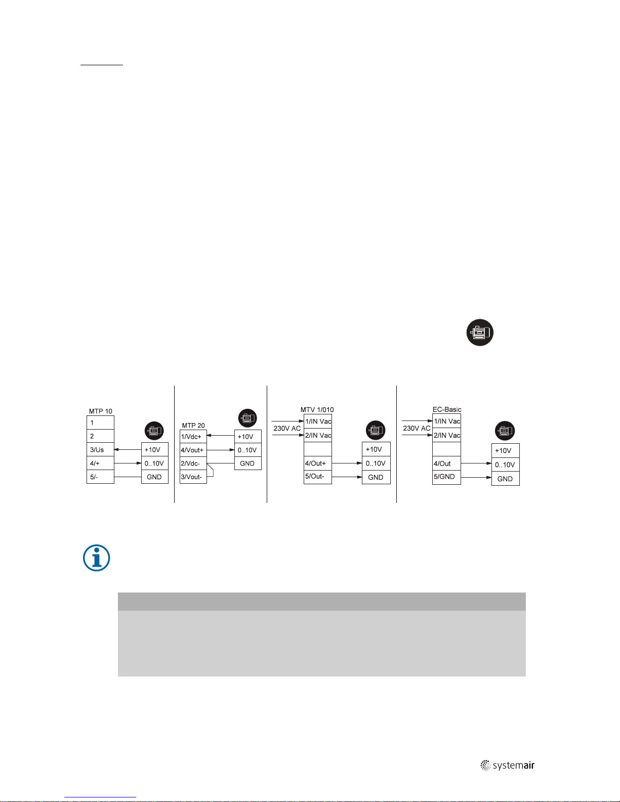
9.1 Electrical connection accessories
The following wiring diagrams show the electrical connections between accessories and
fans (with EC motor) or frequency converters (e.g. FRQ, FRQS, FXDM) which can be
controlled with a 0–10V signal. If you are not sure if your fan is equipped with an EC- motor
please see chapter 6 Name plate and type key, page 9.
motor/frequency
converter
Wire- colours of motors with carried out cables: +10V = red 0..10V = yellow GND = blue
MTP 10 MTP 20
MTV—1/10
EC-Basic
9.2 Protecting the motor
Note:
In fans equipped with an EC motor, there is no additional motor protection needed. The motor protection is
integrated in the electronics of the motor.
Important
Damage to motor due to overcurrent, overload or short circiut.
♦ Lead-out temperature monitors must be integrated in the control circuit in such a way that, if a fault
occurs, the motor cannot switch on again automatically after it has cooled down.
♦ Motor lines and temperature monitor lines should be laid separately on principle.
♦ Without thermal protection: Use a motor protection switch!
| 005
Page 20
16
|
Commissioning
9.3 Variable-speed fans
Warning
Resonant frequencies may result in increased vibration in certain speed ranges. These vibrations may
destroy components.
♦ Only operate the fan outside these speed ranges.
♦ Pass through these speed ranges so quickly that any vibration cannot exceed the admissible resonant
frequency values.
♦ Observe the operating instructions of the frequency converter.
Caution
Damage as a result of incorrect commissioning of the frequency converter.
♦ Install the fan and frequency converter as near as possible to one another.
♦ Use shielded cables.
♦ All components (fan, frequency converter and motor) must be grounded.
♦ We recommend using all-pole sinus filters.
♦ Avoid running the fan via the frequency converter below 10 Hz.
♦ Heating of the motor due to use of a variable frequency drive must be checked in the application by the
customer.
♦ Never exceed the maximum impeller rotation speed indicated on the name plate of the fan.
10 Commissioning
Warranty claims can only be made if commissioning work is carried out correctly and written evidence thereof is
provided.
Safety information
♦ Commissioning may only be carried out by adequately qualified persons, details see Table 1 Qualifications, page 2.
Preconditions
♦ Installation and electrical connection have been
correctly performed.
♦ Residual material from installation and foreign objects
have been removed from the fan and ducts.
♦ Before switching the fan on, check for externally
visible damage and ensure that the protective
equipment functions properly.
♦ Inlet and outlet are free.
♦ Cable glands are tight.
♦ Data on the name plate corresponds with the
connection data.
♦ Safety devices have been fitted.
Tests
During commissioning, the following sequence must be observed:
AC motor EC motor
1. Switch the fan on.
2. Do the tests requested in the commissioning report
(18 Commissioning Report, page 21)
Speed controllable fans: “Measured data at
commissioning” at maximum speed
3. Switch the fan off.
When the mains are switched on, the motor starts an
initialization (a few seconds). After the initialization the
control input is active.
1. Switch the fan on via the control input.
2. Do the tests requested in the commissioning report
(18 Commissioning Report, page 21)
Speed controllable fans: “Measured data at
commissioning” at maximum speed
3. Switch the fan off via the control input.
| 005
Page 21
Operation
|
17
11 Operation
Safety information
Warning: Hazard from electrical voltage or moving components.
♦ The device may only be operated by adequately qualified persons, details see Table 1 Qualifications, page 2.
♦ Only use the fan in accordance with the operating instructions and the operating instructions for the motor.
12 Troubleshooting/maintenance/repair
Safety information
♦ Troubleshooting/maintenance/repair may only be carried out by adequately qualified persons, details see Table 1
Qualifications, page 2.
♦ Observe the 5 rules of electrical safety, see 2.3 5 rules of electrical safety, page 2.
♦ The impeller must be at a standstill.
12.1 Troubleshooting
Table 15 Troubleshooting
Problem Possible causes
Remedy
Fan does not run
smoothly
Impeller imbalance
Rebalancing by a specialist company if possible,
otherwise contact Systemair.
Soiling on the impeller Clean carefully, rebalance
Material decomposition on the
impeller due to aggressive
material conveyed.
Contact Systemair
Impeller rotates in wrong
direction.
Change direction of rotation if possible, otherwise contact
Systemair.
Deformation of impeller due to
excessive temperature.
Ensure that the temperature does not exceed the certified
value/Install new impeller.
Vibrations, oscillations
Check the installation of the fan/check the duct system,
see 8 Installation, page 11.
Air output of fan too
low
Impeller rotates in wrong
direction.
Change direction of rotation if possible, otherwise contact
Systemair.
Wrong wiring configuration (e.g.
Y instead of Delta).
Check and possibly correct the wiring configuration.
Pressure losses too high. Optimize the line routing.
Flow regulators not or only
partly open.
Check opening position on site.
Intake or pressure ducts are
blocked.
Remove the blockage.
Grinding sounds
when starting or
operating the fan
Check if the duct connections of
the fan are strained.
Loosen the duct connections and realign it.
Thermal contacts/
resistors have
triggered
Impeller rotates in wrong
direction.
Change direction of rotation if possible, otherwise contact
Systemair.
Missing phase
In case of a 3 phase standard motor (not EC), check if all 3
phase are present.
Motor overheated
Check the cooling impeller (if used), measure the motor
winding (if possible) / contact Systemair.
Capacitor (if used) not or not
correctly connected.
Connect the capacitor correctly.
Motor blocked
Contact Systemair
| 005
Page 22
18
| Troubleshooting/maintenance/repair
Troubleshooting cont'd
Fan does not reach
nominal speed
Defective motor winding
Contact Systemair
Improperly aligned drive motor
Contact Systemair
Control units (if used) such as
frequency converter or
transformer are set incorrectly.
Correct the settings of the control units.
Mechanical blockage Remove the blockage.
Motor does not
rotate
Faulty supply voltage Check the supply voltage, re-establish the voltage supply.
Faulty connection
Disconnect from the power supply, correct the
connection, see circuit diagram.
Temperature monitor has
responded.
Allow the motor to cool down, find and resolve the cause
of the fault.
Electronics/motor
overheated
Insufficient cooling Improve cooling.
Overloaded motor
Check if the correct fan is used for your application.
Ambient temperature too high Check if the correct fan is used for your application.
Note:
For all other damage/defects, please contact Systemair. Defective safety-relevant fans (for Ex and smoke
extraction applications) must be replaced completely.
12.2 Maintenance
Warranty claims can only be made if maintenance work is carried out correctly and written evidence thereof is
provided.
We recommend regular maintenance intervals to ensure continuous fan operation. These maintenance intervals are
specified in the “Activities” table below. In addition, the operator must carry out follow-up activities such as cleaning,
replacing defective components or other corrective measures. For traceability reasons, a maintenance plan must be
created which documents the work carried out. This must be created by the operator. If the operating conditions are
"extreme", the maintenance intervals must be reduced so that maintenance is carried out more frequently. Examples
of extreme operating conditions:
• Kitchen exhaust fans
• Ambient temperature > 40 ºC or < -10 ºC, or temperature fluctuations > 20 K
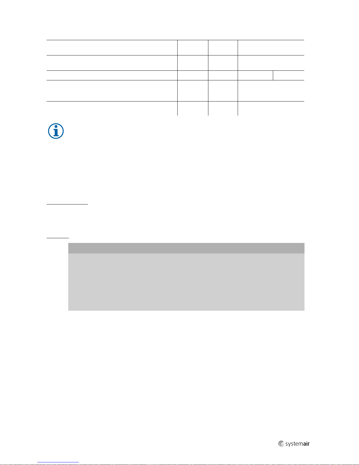
Table 16 Activities
Normal operating
conditions
Extreme operating
conditions
Activity
Every six
months
Annually Quarterly
Every six
months
Check the fan and its components for visible damage,
corrosion and contamination.
X X
Check the impeller for damage and imbalance.
X X
Check the condensate drain is working correctly.
X X
Clean the fan/ventilation system (see 13 Cleaning, page
19).
X X
Check the screwed connections for damages/defects and
check that they are firmly seated.
X
See normal operating
conditions
Check the fan intake is free from contamination.
X X
Check that the fan and its components are being used
correctly.
X
See normal operating
conditions
Check the current consumption and compare this with the
rated data.
X X
| 005
Page 23
Cleaning |
19
Activities cont'd
Check the vibration dampers (if used) are working
correctly and check for visible damage and corrosion.
X
See normal operating
conditions
Check the electrical and mechanical protective equipment
is working correctly.
X
See normal operating
conditions
Check the fan’s rating plate is legible.
X X
Check the connection clamps and screwed cable
connections for damage/defects, and check that they are
firmly seated.
X
See normal operating
conditions
Check the flexible connectors for damage.
X
See normal operating
conditions
Note:
For all other damage/defects, please contact Systemair. Defective safety-relevant fans (for Ex and smoke
extraction applications) must be replaced completely.
12.3 Spare parts
♦ Use original spare parts from Systemair only.
♦ When ordering spare parts, please specify the serial number of the fan. This can be found on the name plate.
13 Cleaning
Safety information
♦ Cleaning may only be carried out by adequately qualified persons, details see Table 1 Qualifications, page 2.
♦ Observe the 5 rules of electrical safety, see 2.3 5 rules of electrical safety, page 2.
♦ The impeller must be at a standstill.
Procedure
Important
Keeping the fan clean extends its service life.
♦ Install a filter monitor.
♦ Do not use steel brushes or sharp-edged objects.
♦ Do not use a high-pressure cleaner (steam jet cleaner) under any circumstances.
♦ Do not bend the fan blades when cleaning.
♦ When cleaning the impeller, pay attention to balance weights that have been positioned
♦ Keep the airways of the fan clear and clean them if necessary with a brush.
14 Deinstallation/dismantling
Deinstall and dismantle the fan in reverse order of installation and electrical connection.
15 Disposal
♦ Ensure material is recycled. Observe national regulations.
♦ The device and the transport packaging are predominantly made from recyclable raw materials.
♦ Disassemble the fan into its components.
♦ Separate the parts according to:
• reusable material
• material groups to be disposed of (metal, plastics, electrical parts, etc.)
| 005
Page 24

20
| EU Declaration of conformity — Roof fans
16 EU Declaration of conformity — Roof fans
Table 17 Roof fans
The manufacturer: Systemair GmbH
Seehöfer Straße 45
97944 Boxberg
Germany
Product designation: Roof fans
Type designation: DVS; DHS; DVSI; DVC/DVCI; DVP
Since year of manufacture:
2016
The manufacturer declares that the above mentioned products in their design and construction and the version
marketed by us complies with the harmonization legislation listed below:
EU directives: 2006/42/EC Machinery directive
2014/30/EU Directive electromagnetic compatibility (EMC)
2011/65/EU RoHS directive
2009/125/EC ErP guidelines
Regulations: 1253/2014 Only for ventilation units above 30W
17 EU Declaration of conformity — Thermo fans
The manufacturer: Systemair GmbH
Seehöfer Straße 45
97944 Boxberg
Germany
Product designation: Thermo fans
Type designation: AxZent; KBR; MUB-K; MUB/T; MUB/T-S; DVN; DVNI
Since year of manufacture:
2018
The manufacturer declares that the above mentioned products in their design and construction and the version
marketed by us complies with the harmonization legislation listed below:
EU directives: 2006/42/EC Machinery directive
2014/30/EU Directive electromagnetic compatibility (EMC)
2011/65/EU RoHS directive
| 005
Page 25
Commissioning Report
|
21
18 Commissioning Report
Warranty claims can only be made if commissioning work is carried out correctly and written evidence thereof is
provided.
Fan
Description:
Article no.: Manufacturing order no.:
Installer
Company: Contact person:
Company address:
Tel. no.: Email:
Operator (Place of installation)
Company: Contact person:
Company address:
Tel. no.: Email:
Type of connection
Yes No
Directly to mains
□ □
0-10 V signal (EC motor)
□ □
via contactor control
□ □
Transformer
□ □
Frequency converter
□ □
Sinus filter
□ □
Shielded cables
□ □
Motor protection
Yes No
Motor protection switch or motor protection relay
□ □
PTC resistor
□ □
Resistance value [Ω]:
Thermal contact
□ □
Electrical motor protection
□ □
Others:
Functional check
Yes No
Impeller easily rotatable (by hand)
□ □
Rotation direction acc. to directional arrow
□ □
Smooth running without unusual noise/
vibrations
□ □
Nominal data - Fan (name plate on fan housing)
Voltage [V]: Current [A]:
Frequency [Hz]: Power [kW]:
Fan impeller speed [rpm]:
Measured data at commissioning
Voltage [V]: Temp. of transported air [°C]:
| 005
Page 26

22
|
Commissioning Report
Current L1 [A]*:
Fan impeller speed [rpm]:
Current L2 [A]: Air volume [m3/s]:
Current L3 [A]:
Differential pressure [Pa]*:
*For single-phase fans, fill in line “Current L1 [A]” *Δ- Pressure between suction-side and discharge of the fan
If an air flow measurement is not possible, this value can be calculated using the following formula:
X
=
Duct cross-section [m²]
Flow speed [m/s]
Grille measurement acc. to VDI 2044
Air volume [m³/s]:
Yes No
Commissioning of the fan successful?
□ □
Date, installer's signature
Date, operator's signature
| 005
Page 27

| 005
Page 28

Roof fans · Installation and Operating Instructions · · en_GB · 2019-02-04 · 005
Systemair GmbH
Seehöfer Str. 45
97944 Boxberg
Germany
Tel.: +49 (0)7930/9272-0
Fax: +49 (0)7930/9273-92
info@systemair.de
www.systemair.de
 Loading...