

Page 1
Air Distribution Products
BIA
Adjustable Displacement Diffuser
Data Sheet
Page 2

2 / 12 | Variable Geometry Diffusers
Table of Contents
Description . . . . . . . . . . . . . . . . . . . . . . . . . . . 3
Design . . . . . . . . . . . . . . . . . . . . . . . . . . . . . 4
Dimensions . . . . . . . . . . . . . . . . . . . . . . . . . . 5
Ordering Code . . . . . . . . . . . . . . . . . . . . . . . . . 6
Technical Parameters . . . . . . . . . . . . . . . . . . . . . 6
Installation, Maintenance & Operation . . . . . . . . . . . . 10
Transport & Storage . . . . . . . . . . . . . . . . . . . . . . 10
Supplement . . . . . . . . . . . . . . . . . . . . . . . . . . 10
Related Products. . . . . . . . . . . . . . . . . . . . . . . . 11
Good to know
Current information on all products is
available at design.systemair.com
Page 3

Variable Geometry Diffusers | 3 / 12
Description
BIA is a variable geometry displacement/induction
hybrid diffuser, mainly intended for air supply in
comfort ventilation systems for industrial-, ofce-
and public halls.
Highlights
• Compact dimensions
• Precise adjustment of different discharge patterns
for heated and cooled air
• Pressure drop independent from the air discharge
mode adjustment
• Manual or motorized adjustment versions
• Easy and quick installation in elevation 0 m to 5 m
Product Types
• BIA-...-HC: Variable geometry displacement/induction
hybrid diffuser with manual geometry adjustment
• BIA-...-MC: Variable geometry displacement/induction
hybrid diffuser with continuous actuator for geometry
adjustment
Fig. 1: Air ow visualisation
Left: vertical discharge, heating mode
Right: horizontal discharge, cooling mode
Page 4
4 / 12 | Variable Geometry Diffusers
Design
The diffuser casing is made from galvanized perforated steel sheet. A version with the casing from satin nish
stainless steel is also available for better protection in case of water condensation in spaces with higher humidity.
The air inlet with rubber gasket ts to the standard circular spiral ducts. The upper part with vertical slit perforation
permits the air discharge in vertical direction with higher face velocity (induction mode). The lower part with
perforation of circular holes permits the air in displacement discharge mode. The internal mechanism adjusts
the ratio between the induction and displacement air discharge. The positioning of the mechanism can be manual
or with electrical (AC 24 V) continuously positioning (DC 0 V … 10 V) actuator. The manual adjustment is possible over
longer distance by a rope bound to the adjustment pull chain, when the diffuser is installed in higher elevation.
The pull chain reaches app. 200 mm under the bottom of the casing. The mechanism assures pressure drop
independent from the adjusted position.
Controls
The diffuser type BIA-…-MC ais equipped by an actuator with AC 24 V power supply and continuous positioning
by the control signal DC 0 V …10 V.
Information about installation, maintenance and operation is available in the “UserManual_BIA” document
on
Systemair DESIGN.
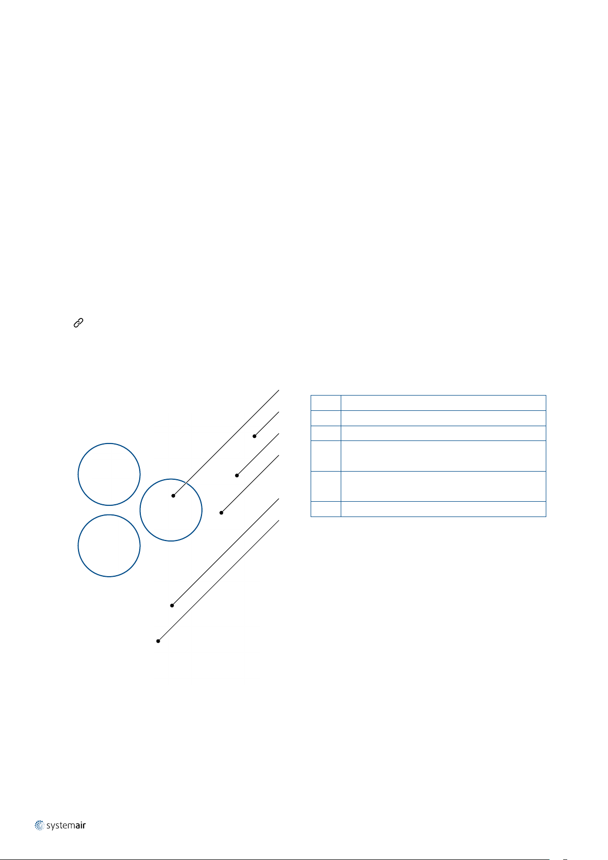
Product Parts
Fig. 2: Components of BIA
4
1
2
3
6
5
Legend
1 Connection for spiral duct with rubber gasket
2 Perforation for vertical induction discharge
3 Perforation for horizontal displacement discharge
Platform with adjustment handle (BIA-...-HC)
4
or adjustment actuator (BIA-...-MC)
Pull chain for manual adjustment (BIA-...-HC),
5
reaches app. 200 mm lower than the casing bottom
6 Position arresting holder for manual adjustment (BIA-...-HC)
Page 5

Setup Possibilities
-45°
BIA-...-HC
Variable Geometry Diffusers | 5 / 12
+45°
0°
U
C
0 V 2 V 10 V
BIA-...-MC
Fig. 4: Different deection mechanism setup and resulting air ow pattern
Dimensions
øD
H
C
Tab. 1: Dimensions of BIA
Type-Size H C øD
BIA-200 550 330 198 4 4,4
BIA-250 700 440 248 6 6,4
BIA-315 850 515 313 9,5 10,3
BIA-400 1100 660 398 15,5 16,3
BIA-500 1350 800 498 23 23,8
BIA-630 1700 970 628 35,5 36,3
m
HC (manual) MC (actuator)
(mm) (kg)
Fig. 3: Dimensions of BIA
Page 6

6 / 12 | Variable Geometry Diffusers
500
700
900
m³/h
m
TH
TH
TV
TV
Ordering Code
Size - Inlet ø (mm) 630
Manual HC
Adjustment Mechanism Type Actuator, continuous position 0 V ... 10 V, AC/DC 24 V power MC
RAL7001 silver grey (galvanized steel) SG
RAL9003 signal white (galvanized steel) SW
Other RAL colour (galvanized steel) RALXXXX
Surface Finish/Material Stainless steel A316 casing only (no paint) A
BIA- - -
200
250
315
400
500
Example of Ordering Code
BIA-200-HC-SW
Diffuser with inlet diameter 200 mm, manually adjustable, made of galvanized steel with RAL9003 signal white
surface nish.
.
Technical Parameters
Legend
p
q
L
L
TH
TV
Pa Pressure drop
s
m3/h
V
WA
PA
x
x
Air ow volume
l/s
dB(A) A-weighted total radiated sound power level
A-weighted total sound pressure level
dB(A)
expressed for 10 m
Throw length, maximum horizontal (TH)
m
and maximum vertical (TV) component
calculated for specic terminal velocity
2
room absorption area
TH, TV
Throw length, maximum horizontal (TH)
and maximum vertical (TV) component
with terminal velocity 0,2 m/s.
TH
TV
x m/s Terminal velocity in range of 0,1 m/s ... 1 m/s
Flow pattern adjustment position
-45°, 0°, 45°
(angle of adjustment shaft
– see Setup Possibilities
on page 5)
Calculation of Air Throw for Different Terminal Velocities
THx = TH · 0,2/x
TV
= TV · 0,2/x
x
Page 7

Variable Geometry Diffusers | 7 / 12
200
300
400
500
600
m³/h6080
100
120
140
160
l/s
4
8
12
16
202428
Pa
25 dB(A)
30 dB(A)
35 dB(A)
40 dB(A)
45 dB(A)
50 dB(A)
25 dB(A)
30 dB(A)
35 dB(A)
40 dB(A)
45 dB(A)
50 dB(A)
200
300
400
500
600
m³/h
0
2.5
5
m
TH
TH
200
300
400
500
600
m³/h
2.540
m
TH
TH
TV
TV
200
300
400
500
600
m³/h
5
0
7
m
TV
TV
400
500
600
700
800
900
1000
m³/h
100
150
200
250
l/s
5
10
15
20
25
Pa
25 dB(A)
30 dB(A)
35 dB(A)
40 dB(A)
45 dB(A)
50 dB(A)
25 dB(A)
30 dB(A)
35 dB(A)
40 dB(A)
45 dB(A)
50 dB(A)
400
500
600
700
800
900
1000
m³/h
0
5
7
m
TH
TH
400
500
600
700
800
900
1000
m³/h
2.5
5
1
m
TH
TH
TV
TV
400
500
600
700
800
900
1000
m³/h
5
9
0
m
TV
TV
SIZE 250
SIZE 200
BIA-200BIA-200
Diagram 1: Pressure drop and radiated A-weighted sound power level
dependent on air ow volume
BIA-200, -45°BIA-200, -45°
BIA-250BIA-250
Diagram 3: Pressure drop and radiated A-weighted sound power level
dependent on air ow volume
BIA-250, -45°BIA-250, -45°
BIA-200, 0°BIA-200, 0°
BIA-200, +45°BIA-200, +45°
Diagram 2: Isothermal air throw length with maximum horizontal (TH)
and maximum vertical (TV) component with terminal velocity 0,2m/s,
dependent on air ow volume and adjustment angle
BIA-250, 0°BIA-250, 0°
BIA-250, +45°BIA-250, +45°
Diagram 4: Isothermal air throw length with maximum horizontal (TH)
and maximum vertical (TV) component with terminal velocity 0,2m/s,
dependent on air ow volume and adjustment angle
Page 8

8 / 12 | Variable Geometry Diffusers
600
800
1000
1200
1400
1600
m³/h
200
240
280
320
360
400
440
l/s
5
10
15
20
25
Pa
25 dB(A)
30 dB(A)
35 dB(A)
40 dB(A)
45 dB(A)
50 dB(A)
25 dB(A)
30 dB(A)
35 dB(A)
40 dB(A)
45 dB(A)
50 dB(A)
600
800
1000
1200
1400
1600
m³/h
0
5
8
m
TH
TH
600
800
1000
1200
1400
1600
m³/h
2.5
51m
TH
TH
TV
TV
600
800
1000
1200
1400
1600
m³/h
5
0
10
m
TV
TV
1000
1200
1400
1600
1800
2000
2200
m³/h
300
400
500
600
l/s
51015
20
Pa
25 dB(A)
30 dB(A)
35 dB(A)
40 dB(A)
45 dB(A)
50 dB(A)
25 dB(A)
30 dB(A)
35 dB(A)
40 dB(A)
45 dB(A)
50 dB(A)
1000
1200
1400
1600
1800
2000
2200
m³/h
0
5
8
m
TH
TH
1000
1200
1400
1600
1800
2000
2200
m³/h
2.5
51m
TH
TH
TV
TV
1000
1200
1400
1600
1800
2000
2200
m³/h
5
0
10
m
TV
TV
SIZE 400
SIZE 315
BIA-315BIA-315
Diagram 5: Pressure drop and radiated A-weighted sound power level
dependent on air ow volume
BIA-315, -45°BIA-315, -45°
BIA-400BIA-400
Diagram 7: Pressure drop and radiated A-weighted sound power level
dependent on air ow volume
BIA-400, -45°BIA-400, -45°
BIA-315, 0°BIA-315, 0°
BIA-315, +45°BIA-315, +45°
Diagram 6: Isothermal air throw length with maximum horizontal (TH)
and maximum vertical (TV) component with terminal velocity 0,2m/s,
dependent on air ow volume and adjustment angle
BIA-400, 0°BIA-400, 0°
BIA-400, +45°BIA-400, +45°
Diagram 8: Isothermal air throw length with maximum horizontal (TH)
and maximum vertical (TV) component with terminal velocity 0,2m/s,
dependent on air ow volume and adjustment angle
Page 9

Variable Geometry Diffusers | 9 / 12
2000
2500
3000
3500
m³/h
500
600
700
800
900
1000
l/s
2468101214
16
Pa
25 dB(A)
30 dB(A)
35 dB(A)
40 dB(A)
45 dB(A)
50 dB(A)
25 dB(A)
30 dB(A)
35 dB(A)
40 dB(A)
45 dB(A)
50 dB(A)
2800
3200
3600
4000
4400
4800
5200
m³/h
800
1000
1200
1400
l/s
2
4
6
8
10
12
14
Pa
25 dB(A)
30 dB(A)
35 dB(A)
40 dB(A)
45 dB(A)
50 dB(A)
25 dB(A)
30 dB(A)
35 dB(A)
40 dB(A)
45 dB(A)
50 dB(A)
2000
2500
3000
3500
m³/h
0
5
8
m
TH
TH
2000
2500
3000
3500
m³/h
2.5
1
5
m
TH
TH
TV
TV
2000
2500
3000
3500
m³/h
5
0
10
m
TV
TV
2800
3200
3600
4000
4400
4800
5200
m³/h
0
5
8
m
TH
TH
2800
3200
3600
4000
4400
4800
5200
m³/h
2.5
51m
TH
TH
TV
TV
2800
3200
3600
4000
4400
4800
5200
m³/h
5
0
10
m
TV
TV
SIZE 630
SIZE 500
BIA-500BIA-500
Diagram 9: Pressure drop and radiated A-weighted sound power level
dependent on air ow volume
BIA-500, -45°BIA-500, -45°
BIA-630BIA-630
Diagram 11: Pressure drop and radiated A-weighted sound power level
dependent on air ow volume
BIA-630, -45°BIA-630, -45°
BIA-500, 0°BIA-500, 0°
BIA-500, +45°BIA-500, +45°
Diagram 10: Isothermal air throw length with maximum horizontal (TH)
and maximum vertical (TV) component with terminal velocity 0,2m/s,
dependent on air ow volume and adjustment angle
BIA-630, 0°BIA-630, 0°
BIA-630, +45°BIA-630, +45°
Diagram 12: Isothermal air throw length with maximum horizontal (TH)
and maximum vertical (TV) component with terminal velocity 0,2m/s,
dependent on air ow volume and adjustment angle
Page 10

10 / 12 | Variable Geometry Diffusers
Installation, Maintenance & Operation
Information about installation, maintenance and operation is available in the “UserManual_BIA” document
on
Systemair DESIGN.
Dry indoor conditions with an operation temperature range of -20°C to +50°C.
Transport & Storage
Dry indoor conditions with a temperature range of -40°C to +50°C.
Supplement
Any deviations from the technical specications contained herein and the terms should be discussed
with the manufacturer. We reserve the right to make any changes to the product without prior notice,
provided that these changes do not affect the quality of the product and the required parameters.
Current information on all products is available on
Systemair DESIGN.
Page 11

Variable Geometry Diffusers | 11 / 12
Related Products
BURE
Variable Geometry Diffusers
Product information is available within the “DataSheet_BURE” technical documentation
on
Systemair DESIGN.
VVT
Thermo-Adjustable Diffuser
Product information is available within the “DataSheet_VVT” technical documentation
on
Systemair DESIGN.
Page 12

www.systemair.com
Systemair Production a.s. · DataSheet_BIA_EN_202006
 Loading...