

Page 1
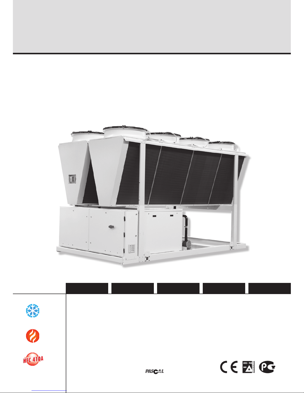
Air Cooled Water Chillers and Heat Pumps
Refroidisseurs de liquide à condensation par air et pompes à chaleur air-eau
Luftgekühlte Flüssigkeitskühler und Wärmepumpen
Refrigeratori d’Acqua e Pompe di Calore Raffreddati ad Aria
Enfriadores de Agua y Bomba de Calor Condensadas con Aire
Installation and maintenance manual
Manuel d'installation et de maintenance
Installations- und Wartungshandbuch
Manuale di installazione e di manutenzione
Manual de instalación y de mantenimiento
Part number / Code / Code / Codice / Código: 342605/A
Supersedes / Annule et remplace / Annulliert und ersetzt / Annulla e sostituisce /
Anula y sustituye: 035B09058-000
Notified Body / Organisme Notifié / Benannte Zertifizierungsstelle / Organismo
Notificato / Organismo Notificado N°. 1115
”
English Deutsch EspañolItalianoFrançais
380
634 kW
418
702 kW
AQWL/AQWH
AQWC/AQWR
ISO 9001:2008 certified management system
Page 2

Page 3

1
English
Table of Contents
1 - FOREWORD
1.1 Introduction..........................................................................2
1.2 Warranty..............................................................................2
1.3 Emergency stop/Normal stop ...............................................2
1.4 An introduction to this manual ..............................................2
2 - SAFETY
2.1 Foreword..............................................................................3
2.2 Definitions............................................................................ 4
2.3 Access to the unit ...............................................................4
2.4 General precautions..............................................................4
2.5 Precautions against residual risks.........................................4
2.6 Precautions during maintenance operations ..........................5
2.7 Safety labels ................................................................. 6 & 7
2.8 Safety regulations........................................................8 to 10
3 - TRANSPORT, LIFTING AND POSITIONING
3.1 Inspection ..........................................................................11
3.2 Lifting ................................................................................11
3.3 Anchoring ..........................................................................12
3.4 Storage ..............................................................................12
4 - INSTALLATION
4.1 Positioning of the unit......................................................... 13
4.2 Spring isolator installation.......................................... 13 & 14
4.3 External hydraulic circuit............................................ 14 & 15
4.4 Hydraulic connections .......................................................15
4.5 Draining the defrosting waste water (AQWH only) .............. 15
4.6 Power supply .....................................................................16
4.7 Electrical connections................................................ 16 & 17
4.8 Connecting plate-type evaporator
temperature sensors ................................................. 18 & 19
4.9 Total heat recovery features................................................19
5 - START-UP
5.1 Preliminary check...............................................................20
5.2 Start-up .............................................................................20
5.3 Checking the operation.......................................................20
5.4 Delivery to the customer..................................................... 20
6 - CONTROL
6.1 The “Chiller Control” system...............................................21
6.2 Display...............................................................................22
6.3 Keyboard ...........................................................................22
6.4 Protection and Safety Equipment ........................................25
6.5 HPF version configuration................................................... 26
7 - PRODUCT DESCRIPTION
7.1 Introduction........................................................................27
7.2 General specifications ........................................................27
7.3 Compressors .....................................................................27
7.4 Refrigeration circuits ..........................................................27
7.5 Water heat exchanger.........................................................27
7.6 Air heat exchanger..............................................................27
7.7 Fans...................................................................................27
7.8 Electrical power supply and control system .......................28
7.9 Accessories ......................................................................28
8 - TECHNICAL DATA
8.1 Pressure drops...................................................................33
8.2 Technical data ........................................................... 34 to 43
8.3 Unit electrical data..................................................... 44 & 45
8.4 Hydraulic Features..................................................... 46 & 47
8.5 Position of shock adsorbers
and weight distribution on supports ....................................48
8.6 Dimensional Drawings............................................... 49 to 51
8.7 Service spaces................................................................... 52
9 - MAINTENANCE
9.1 General requirements ........................................................53
9.2 Planned maintenance .........................................................53
9.3 Refrigerant charge.............................................................. 54
9.4 Compressor .......................................................................54
9.5 Condenser ........................................................................ 54
9.6 Fans...................................................................................54
9.7 Dehydrating filter ................................................................54
9.8 Sight glass.........................................................................55
9.9 Electronic expansion valve.................................................. 55
9.10 Evaporator .........................................................................55
10 - TROUBLESHOOTING .......................................... 56
11 - SPARE PARTS
11.1 Spare par t list.....................................................................57
11.2 Oil for compressors............................................................57
11.3 Wiring diagrams ................................................................. 57
12 - DISMANTLING, DEMOLITION AND SCRAPPING
12.1 Generalities ........................................................................58
Page 4
2
1 - Introdução
1 - Foreword
1.1 Introduction
Units, manufactured to state-of-the-art design and implementation
standards, ensure top performance, reliability and fitness to any type
of air-conditioning systems.
These units are designed for cooling water or glycoled water (and for
water heating in heat pump models) and are unfit for any purposes
other than those specified in this manual.
This manual includes all the informatio n required for a proper
installation of the u nits, as well as the relevant operati ng and
maintenance instructions.
It is therefore recommended to read this manual carefully before
installation or any operation on the machine. The chiller installation
and maintenance must be carried out by skilled personnel only
(where possible, by one of Authorised Service Centers).
The manufacturer may not be held liable for any damage to people or
property caused by improper installation, start-up and/or improper
use of the unit and/or failure to implement the procedures and
instructions included in this manual.
1.2 Warranty
These units are delivered complete, tested and ready for being
operated. Any form of warranty will become null and void in the event
that the appliance is modified without manufacturer’s preliminary
written authorisation.
This warranty shall apply providing that the installation instructions
have been complied with (either issued by manufacturer, or deriving
from the current practice), and the Form 1 (“Start-up”) has been
filled-in and mailed to manufacturer (attn. After-Sales Service).
In order for this warranty to be valid, the following conditions shall be
met :
QThe machine must be operated only by skilled personnel from
Authorised After-Sales Service.
QMaintenance must be performed only by skilled personnel - from
one of Authorised After-Sales Centers.
QUse only original spare parts.
QCarry out all the planned maintenance provided for by this manual
in a timely and proper way.
Failure to comply with any of these conditions will automatically void
the warranty.
1.3 Emergency stop / Normal stop
The emergency stop of the unit can be enabled using the master
switch on the control panel (move down the lever).
For a normal stop, press the relevant push-buttons.
To restart the appliance, follow the procedure detailed in this manual.
1.4 An introduction to the manual
For safety reasons, it is imperative to follow the instructions given in
this manual. In case of any damage caused by non-compliance with
these instructions, the warranty will immediately become null and
void.
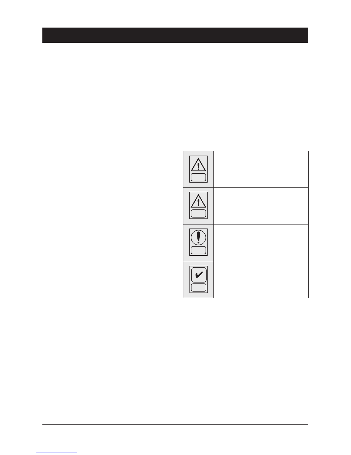
Conventions used throughout the manual:
DANGER
The Danger sign recalls your attention to a
certain procedure or practice which, if not
followed, may result in serious damage to
people and property.
The Warning sign precedes those procedures
that, if not followed, may result in serious
damage to the appliance.
The Notes contain important observations.
The Useful Tips provide valuable information
that optimises the efficiency of the appliance.
This manual and its contents, as well as the documentation which
accompanies the unit, are and remain the property of manufacturer,
whic h re serves any and all righ ts t hereon. This ma nu al may
not be copied, in whole or in part, without manufacturer’s written
authorization.
WARNING
NOTE
USEFUL TIPS
Page 5
3
English
2 - Safety
2.1 Foreword
These units must be installed in conformity with the
provisions of Machinery Directive 2006/42/EC, Low Voltage
Directive 2006/95/EC, Pressure Vessels Directive 97/23/
EC, Electromagnetic Interference Directive 2004/108/EC,
as well as with other regulations applicable in the country
of installation. If these provisions are not complied with, the
unit must not be operated.
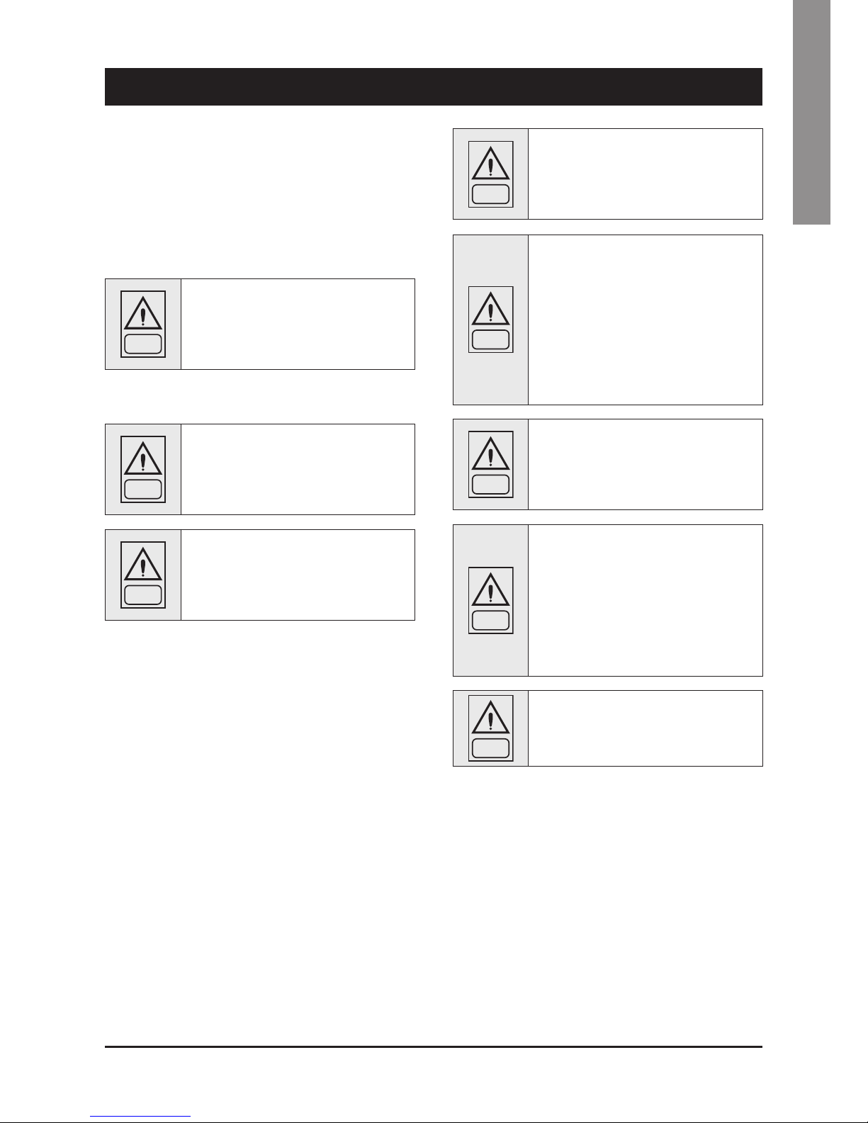
DANGER
The unit must be grounded, and no
installation and/or maintenance operations
may be carried out before deenergising the
electrical panel of the unit.
Failure to respect the safety measures mentioned above may result
in electrocution hazard and fire in the presence of any short-circuits.
DANGER
Inside the heat exchangers, the compressors
and the refrigeration lines, this unit contains
liqu id and ga seous re frigera n t under
pressure. The release of this refrigerant may
be dangerous and cause injuries.
DANGER
The units are not designed to be operated with
natural refrigerants, such as hydrocarbons.
Manufacturer may not be held liable for any
problems deriving from the replacement
of original refrigerant or the introduction of
hydrocarbons.
Units are designed and manufactured according to the requirements
of European Standard PED 97/23/EC (pressure vessels).
QThe used refrigerants are included in group II (non-hazardous
fluids).
QThe maximum working pressure values are mentioned on the
unit’s data plate.
QSuitable safety devices (pressure switches and safety valves)
have been provided, to prevent any anomalous overpressure
inside the plant.
QThe vents of the safety valves are positioned and oriented in such
a way as to reduce the risk of contact with the operator, in the
event that the valve is operated. Anyway, the installer will convey
the discharge of the valves far from the unit.
QDedicated guards (removable panels with tools) and danger signs
indicate the presence of hot pipes or components (high surface
temperature).
DANGER
The guards of the fans (only for units provided
with air heat exchangers) must be always
mounted and must never be removed before
de-energising the appliance.
DANGER
It is the User’s responsibility to ensure that
the unit is fit for the conditions of intended use
and that both installation and maintenance are
carried out by experienced personnel, capable
of resp ecti ng all th e recomme ndat ions
provided by this manual.
It is important that the unit is adequately
supported, as detailed in this manual. Noncompliance with these recommendations may
create hazardous situations for the personnel.
DANGER
The unit must rest on a base which meets the
characteristics specified in this manual; a
base with inadequate characteristics is likely
to become a source of serious injury to the
personnel.
WARNING
Th e unit ha s not bee n design to withst and
loads and/or stress that may be transmitted by
adjacent units, piping and/or structures.
Each external load or stress transmitted to the
unit ma y break or cause breakdowns in t he
unit’s structure, as well as serious dangers to
people. In these cases, any form of warranty will
automatically become null and void.
WARNING
The packaging material must not be disposed of
in the surrounding environment or burnt.
Page 6

4
2.2 Definitions
OWNER: means the legal representative of the company, body or
individual who owns the plant where unit has been installed; he/she
has the responsibility of making sure that all the safety regulations
specified in this manual are complied with, along with the national
laws in force.
INSTALLER: means the legal representative of the company who
has been given by the owner the job of positioning and performing
the hydraulic, electric and other connections of unit to the plant: he/
she is responsible for handling and properly installing the appliance,
as specified in this manual and according to the national regulations
in force.
OPERATOR: means a person authorised by the owner to do on unit
all the regulation and control operations expressly described in this
manual, that must be strictly complied with, without exceeding the
scope of the tasks entrusted to him.
ENGINEER: means a person authorised directly by manufacturer or,
in all EC countries, excluding Italy, under his full responsibility, by
the distributor of product, to perform any routine and extraordinary
maintenance operations, as well as any regulation, control, servicing
operations and the replacement of pieces, as may be necessary
during the life of the unit.
2.3 Access to the unit
The unit must be placed in an area which can be accessed also
by OPERATORS and ENGINEERS; ot herwise the unit must be
surrounded by a fence at not less than 2 meters from the external
surface of the machine.
OPERATORS and ENGINEERS must enter the fenced area only
after wearing suitable clothing (safety shoes, gloves, helmet etc.).
The INSTALLER personnel or any other visitor must always be
accompanied by an OPERATOR.
For no reason shall any unauthorised personnel be left alone in
contact with the unit.
2.4 General precautions
The OPERATOR must simply use the controls of the unit; he must not
open any panel, other than the one providing access to the control
module.
The INSTALLER must simply work on the connections between plant
and machine; he must not open any panels of the machine and he
must not enable any control.
When you approach or work on the unit, follow the precautions listed
below:
Qdo not wear loose clothing or jewellery or any other accessory tat
may be caught in moving parts
Qwear suitable personal protective equipment (gloves, goggles
etc.) when you have to work in the presence of free flames
(welding operations) or with compressed air
Qif the unit is placed in a closed room, wear ear protection devices
Qcut off connecting pipes, drain them in order to balance the
pressure to the atmospheric value before disconnecting them,
disassemble connections, filters, joints or other line items
Qdo not use your hands to check for any pressure drops
Quse tools in a good state of repair; be sure to have understood the
instructions before using them
Qbe sure to have removed all tools, electrical cables and any other
objects before closing and starting the unit again
2.5 Precautions against residual risks
Prevention of residual risks caused by the control
system
Qbe sure to have perfectly understood the operating instructions
before carrying out any operation on the control panel
Qwhen you have to work on the control panel, keep always the
operating instructions within reach
Qstart the unit only after you have checked its perfect connection to
the plant
Qpromptly inform the ENGINEER about any alarm involving the unit
Qdo not reset manual restoration alarms unless you have identified
and removed their cause
Prevention of residual mechanical risks
Qinstall the unit according to the instructions provided in this
manual
Qcarry out all the periodical maintenance operations prescribed by
this manual
Qwear a protective helmet before accessing the interior of the unit
Qbefore opening any panelling of the machine, make sure that it is
secured to it by hinges
Qdo not touch air condensation coils without wearing protective
gloves
Qdo not remove the guards from moving elements while the unit is
running
Qcheck the correct position of the moving elements’ guards before
restarting the unit
Prevention of residual electrical risks
Qconnect the unit to the mains according to the instructions
provided in this manual
Qperiodically carry out all the maintenance operations specified by
this manual
Qdisconnect the unit from the mains by the external disconnecting
switch before opening the electrical board
Qcheck the proper grounding of the unit before start-up
Qcheck all the electrical connections, the connecting cables, and in
particular the insulation; replace worn or damaged cables
2 - Safety (continued)
Page 7

5
English
Qperiodically check the board’s internal wiring
Qdo n ot use cables h aving an in ad equate se ct ion or flyi ng
connections, even for limited periods of time or in an emergency
Prevention of other residual risks
Qmake sure that the connections to the unit c on form to the
instructions provided in this manual and on the unit’s panelling
Qif you have to disassemble a piece, make sure that it has been
properly mounted again before restarting the unit
Qdo not touch the delivery pipes from the compressor, the
compresso r and any othe r piping or component ins ide the
machine before wearing protective gloves
Qkeep a fire extinguisher fir for electrical appliances near the
machine
Qon the units installed indoor, connect the safety valve of the
refrigeration circuit to a piping network that can channel any
overflowing refrigerant outside
Qremove and leak of fluid inside and outside the unit
Qcollect the waste liquids and dry any oil spillage
Qperiodically clean the compressor compartment, to remove any
fouling
Qdo not store flammable liquids near the unit
Qdo not disperse the refrigerant and the lubricating oil into the
environment
Qweld only empty pipes; do not approach flames or other sources
of heat to refrigerant pipes
Qdo not bend/hit pipes containing fluids under pressure
2.6 Precautions during maintenance operations
Maintenance operations can be carried out by authorised technicians
only.
Before performing any maintenance operations:
Qdisc o n nect the uni t f rom th e m a ins w ith the e x ternal
disconnecting switch
2 - Safety (continued)
Qplace a warning sign “do not turn on - maintenance in progress”
on the external disconnecting switch
Qmake sure that on-off remote controls are inhibited
Qwear suitable personal protective equipment (helmet, safety
gloves, goggles and shoes etc.)
To carry out an y measur em en ts or checks which require the
activation of the machine:
Qwork with the electrical board open only for the necessary time
Qclose the electrical board as soon as the measurement or check
has been completed
Qfor outdoor units, do not carry out any operations in the presence
of dangerous climatic conditions (rain, snow, mist etc.)
The following precautions must be always adopted:
Qdo n ot scatter th e fluids of t he refriger at ion circu it in the
surrounding environment
Qwhen replacing an eprom or electronic cards, use always suitable
devices (extractor, antistatic bracelet, etc.)
Qto replace a compressor, the evaporator, the condensing coils or
any other weighty element, make sure that the lifting equipment is
consistent with the weight to be lifted
Qin air units with independent compressor compartment, do not
access the fan compartment unless you have disconnected the
machine by the disconnecting switch on the board and you have
placed a warning sign “do not turn on - maintenance in progress”
Qcontact manufacturer for any modifications to the refrigeration,
hydraulic or wiring diagram of the unit, as well as to its control
logics
Qcontact manufacturer if it is necessary to perform very difficult
disassembly and assembly operations
Quse only orig i nal s p are p arts purc h ased dire c tly f rom
manufacturer or the official retailers of the companies on the
recommended spare parts list
Qcontact manufacturer if it is necessary to handle the unit one year
after its positioning on site or if you wish to dismantle it.
Page 8
6
2 - Safety (continued)
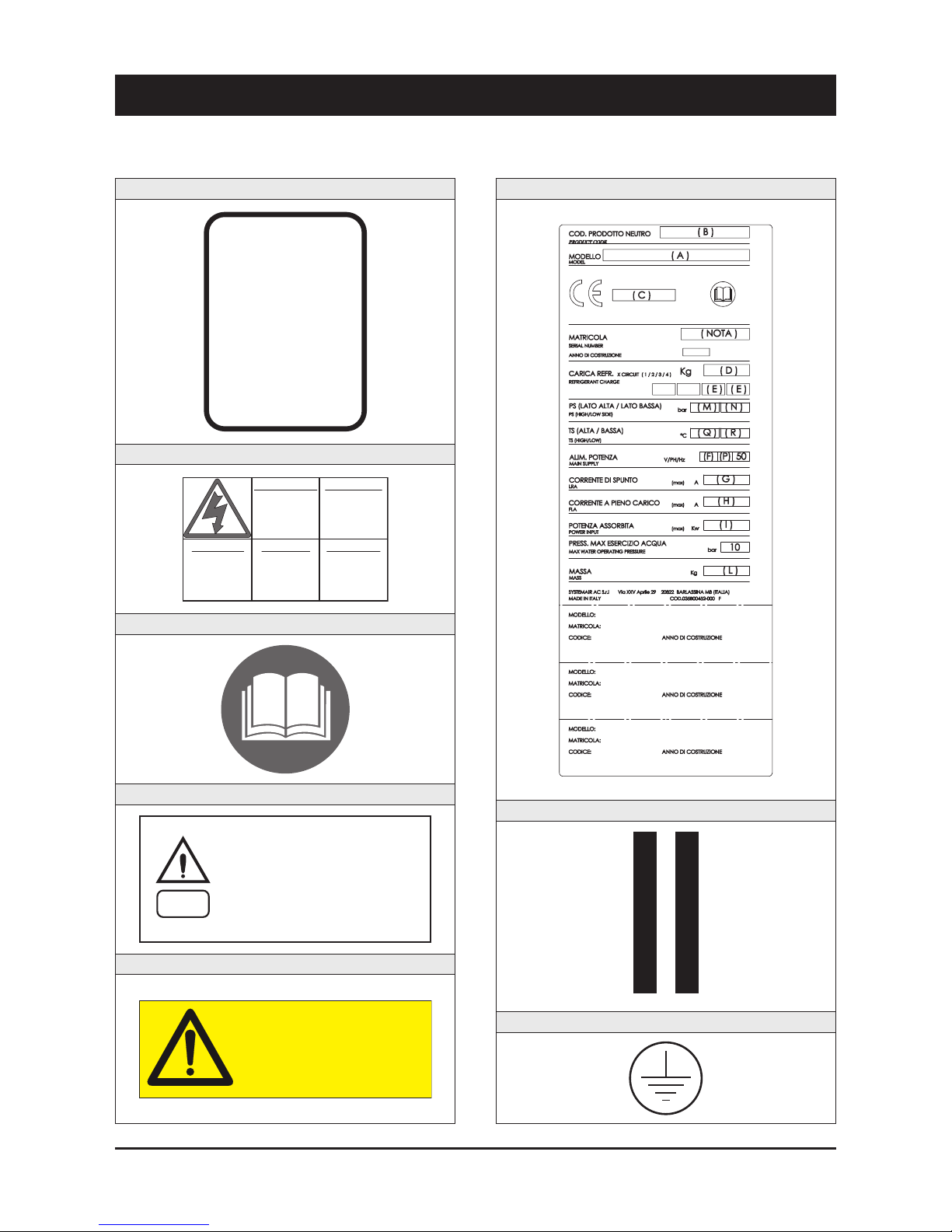
2.7 Safety labels
Identification of the refrigerant - External door
USARE SOLO
R 410A
E
RECUPERARE FLUIDO - NON DISPERDERE NELL’AMBIENTE - REGOLAMENTO CEE N° 3093/94
RECOVER - DO NOT VENT - EEC REGULATION N° 3093/94
SPECIAL ESTER OIL
USE ONLY
Electrical warning - Adjacent to the master switch
ATTENZIONE !
Prima di
aprire togliere
tensione
CAUTION !
Disconnect
electrical
supply before
opening
ACHTUNG !
Vor offne n des
gehauses
hauptschalter
ausschalten
ATENCION !
Cor tar la
corrente antes
de abrir
el aparato
ATTENTION !
Enlever
l’alimentation
electrique
avant d’ouvrir
Read the instruction on the electrical board
On the compressor box
WARNING
Circuit drain - Outside, on the right-hand front column
ATTENTION! Don’t leave the unit with water inside hydraulic circuit during
winter or when it is in stand by.
ATTENZIONE! Non lasciare l’unità con acqua nel circuito idraulico durante
l’inverno o quando non è funzionante.
ATTENTION! Ne laissez pas l’unitè avec de l’eau dans le circuit hydraulique
pendant l’hiver ou quand elle ne travaille pas.
WARNUNG! Lassen Sie nicht das Wasser in die Schaltung während des
Winters oder wenn es nicht funktionient.
¡ATENCÍON! No deje el agua en el circuito hidráulico durante el invierno o
cuando no esta trabajando.
Identification of the unit - Outside, on the right-hand front column
Gravity centre - Base
TENERE SU QUESTA LINEA
GANCIO DI SOLLEVAMENTO
KEEP LIFT HOOK
ON THIS LINE
Grounding connection on the electrical board, adjacent to the connection
DO NOT OPEN THE PANEL
WHILE UNIT IS RUNNING
Page 9
7
English
2 - Safety (continued)
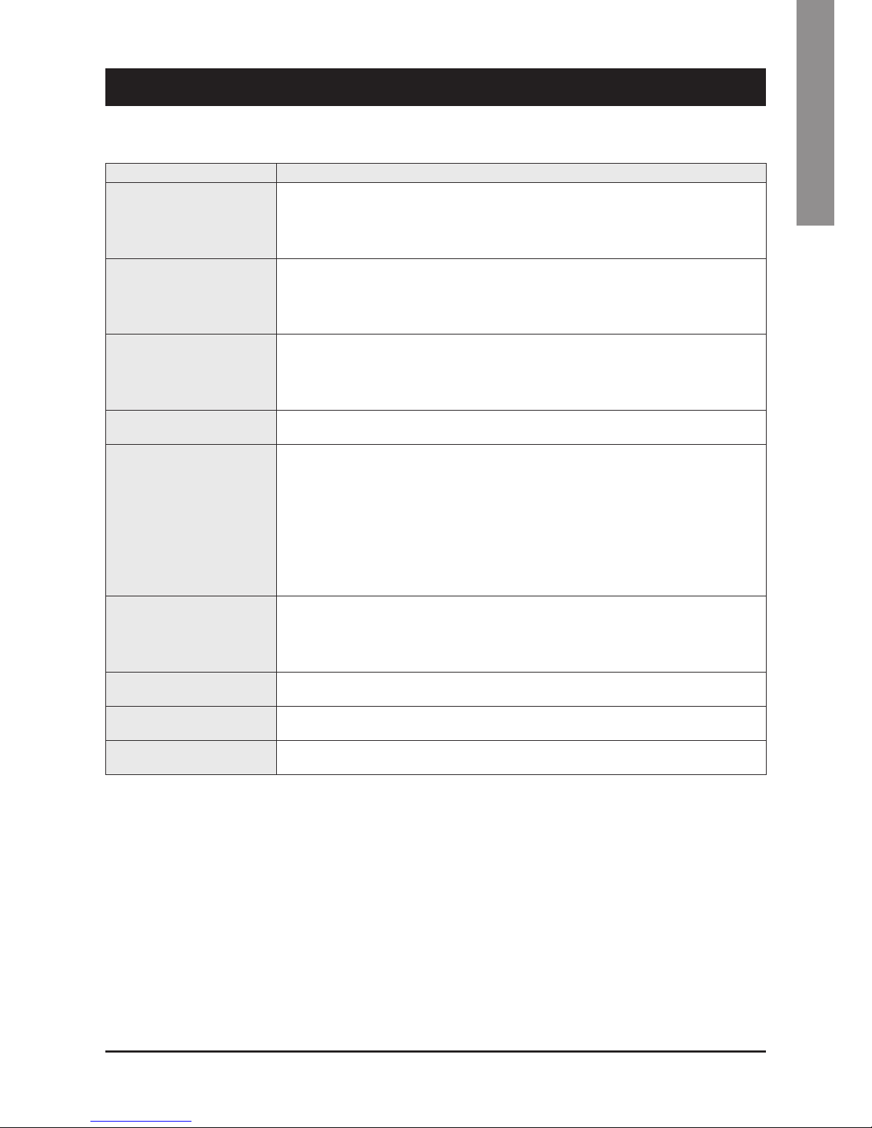
Final Test Certificate - Inside the external door
On the coil
ATTENZIONE! BORDI TAGLIENTI
VORSICHT! SCHARFE RÄNDER
CAUTION! SHARP EDGES
ATTENTION! BORDS COUPANTS
ATENCION! PERFIL AFILADO
Warning - Safety valve vents
Warning - High temperature
zone adjacent to hot pipes or
components
Start-up warning - Outside the door
of the electrical board
ATTENZIONE
INSERIRE LE RESISTENZE DI RISCALDAMENTO OLIO ALMENO 12
ORE PRIMA DI OGNI AVVIAMENTO (SE PREVISTE)
PRIMA DELLA MESSA IN TENSIONE ASSICURARSI CHE LE VITI DEI
CIRCUITI ELETTRICI SIANO SERRATE COMPLETAMENTE
WARNING
ENERGIZE THE CRANCKCASE HEATER FOR AT LEAST 12 HOURS
BEFORE EACH STARTING (IF FITTED)
BEFORE TIGHTENING-UP, TO TIGHTEN ALL TERMINAL SCREWS
ESPECIALLY THOSE IN MAIN CIRCUIT
WARNUNG
OLSUMPFHEIZUNG (FALLS VORHANDEN) 12 STUNDEN VOR DEM
START EINSCHALTEN
VOR INBETRIEBNAHME ALLE SCHRAUBENVERBINDUNGEN
NACHZIEHEN, BESONDERS DIE ELEKTRISCHEN ANSCHLUSSE
ATTENTION
ALIMENTER ELECTRIQUEMENT LA RESISTANCE DE CARTER AU
MOINS 12 HEURES AVANT CHAQUE DEMARRAGE (SI MONTE SUR
LE PRODUIT)
AVANT DE DEMARRER LA MACHINE, VERIFIER LE SERRAGE DE
TOUTES LES BORNES A VIS, SPECIALEMENT DANS LE BOITIER
ELECTRIQUE
ATENTION
ATENCIÓN ALIMENTAR ELÉCTRICAMENTE LA RESISTENCIA DE
CARTER AL MENOS 12 HORAS ANTES DE CADA PUESTA EN
MARCHA (SI ESTA EQUIPADA EN LA UNIDAD)
ANTES DE LA PUESTA EN MARCHA, COMPROBAR QUE LOS
BORNES ESTAN BIEN APRETADOS, ESPECIALMENTE EN EL
CUADRO ELÉCTRICO
035B00057-000 MADE IN ITALY
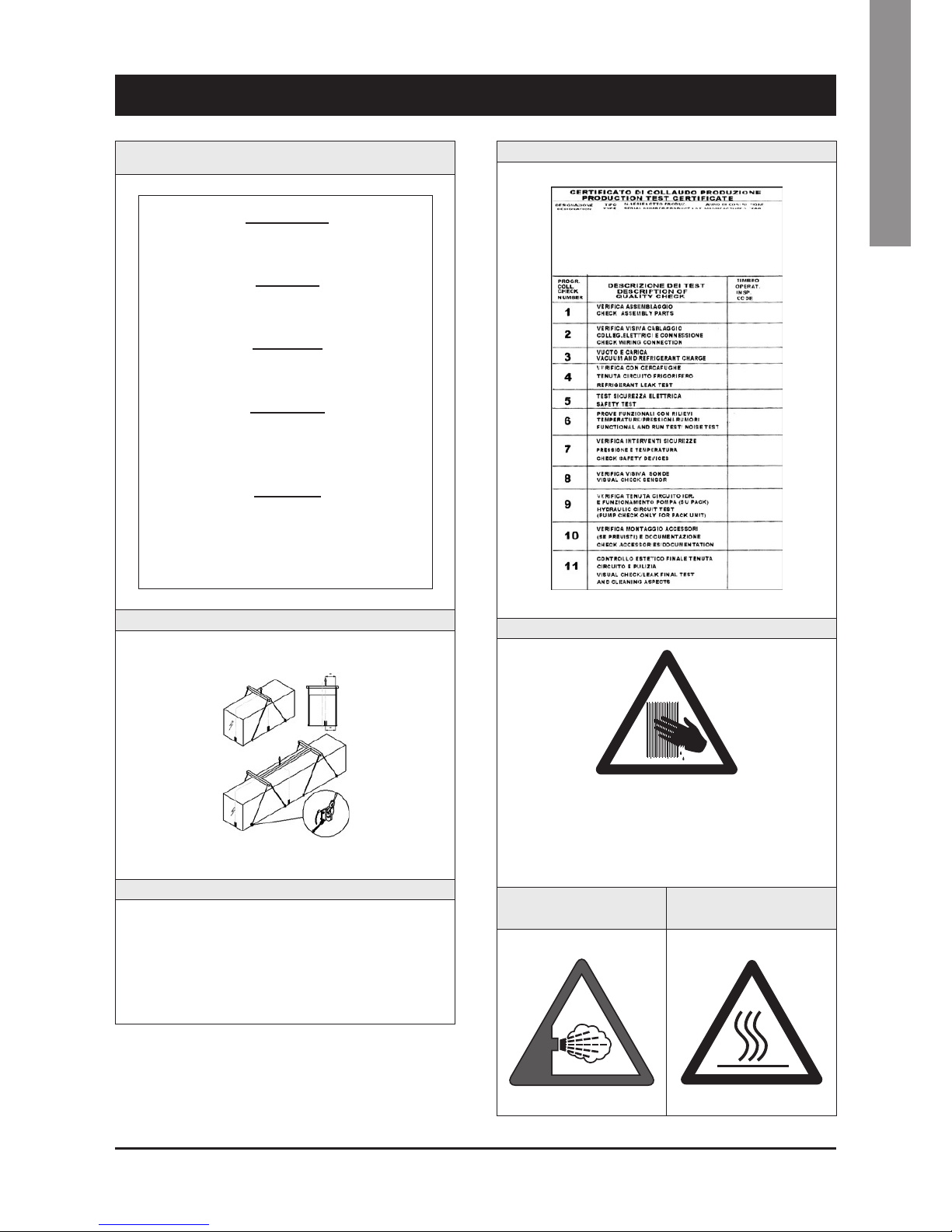
Instruction for the lifting
Fitting identification - Adjacent to fittings
EIN - INLET
ENTRÉE - ENTRATA
AUS - OUTLET
SORTIE - USCITA
Page 10

8
2 - Safety (continued)
REFRIGERANT DATA SAFETY DATA: R410A
Toxicity Low
Contact with skin
If sprayed, the refrigerant is likely to cause frost burns. If absorbed by the skin, the danger is very limited;
it may cause a slight irritation, and the liquid is degreasing. Unfreeze the affected skin with water.
Remove the contaminated clothes with great care - in the presence of frost burns, the clothes may stick
to the skin. Wash with plenty of warm water the affected skin.
In the presence of symptoms such as irritation or blisters, obtain medical attention.
Contact with eyes
Vapours do not cause harmful effects. The spraying of refrigerant may cause frost burns.
Wash immediately with a proper solution or with tap water for at least 10 minutes, and then obtain
medical attention.
Ingestion
Very unlikely - should something happen, it will cause frost burns.
Do not induce vomiting. Only if the patient is conscious, wash out mouth with water and give some
250 ml of water to drink. Then, obtain medical attention.
Inhalation
R410A: remarkable concentrations in the air may have an anaesthetic effect, up to fainting.
The exposure to considerable amounts may cause irregular heartbeat, up to the sudden death of the
patient. Very high concentrations may result in the risk of asphyxia, due to the reduction in the oxygen
percentage in the atmosphere. Remove the patient to fresh air and keep warm and at rest.
If necessary, give oxygen. In case of breathing difficulties or arrest, proceed with artificial respiration.
In case of cardiac arrest, proceed with cardiac massage. Then, obtain medical attention.
Recommendations
Semiotics or support therapy is recommended. Cardiac sensitisation has been observed that, in
the presence of circulating catecholamines such as adrenalin, may cause cardiac arrhythmia and
accordingly, in case of exposure to high concentrations, cardiac arrest.
Prolonged exposure
R410A: a study on the effects of exposure to 50,000 ppm during the whole life of rats has identified the
development of benign testicle tumour.
This situation should therefore be negligible for personnel exposed to concentrations equal to or lower
than professional levels.
Professional levels R410A: Recommended threshold: 1000 ppm v/v - 8 hours TWA.
Stability R410A: Not specified
Conditions to avoid Do not use in the presence of flames, burning surfaces and excess humidity.
Hazardous reactions
May react with sodium, potassium, barium and other alkaline metals.
Incompatible substances: magnesium and alloys with magnesium concentrations > 2%.
Hazardous decomposition
products
R410A: Halogen acids produced by thermal decomposition and hydrolysis.
2.8 Safety regulations
Page 11
9
English
2 - Safety (continued)
REFRIGERANT DATA SAFETY DATA: R410A
General precautions
Do not inhale concentrated vapours. Their concentration in the atmosphere should not exceed the
minimum preset values and should be maintained below the professional threshold. Being more weighty
than the air, the vapour concentrates on the bottom, in narrow areas. Therefore, the exhaust system must
work at low level.
Respiratory system protection
If you are in doubt about the concentration in the atmosphere, it is recommended to wear a respirator
approved by an accident-prevention
Authority, of the independent or oxygen type.
Storage
Cylinders must be stored in a dry and fresh place, free from any fire hazard, far from direct sunlight or
other sources of heat, radiators etc.
Keep a temperature below 50 °C.
Protective clothing Wear overalls, protective gloves and goggles or a mask.
Accidental release measures
It is important to wear protective clothing and a respirator.
Stop the source of the leak, if you can do this without danger. Negligible leaks can be left evaporating
under the sun, providing that the room is well ventilated.
Considerable leaks: ventilate the room. Reduce the leak with sand, earth or other absorbing substances.
Make sure that the liquid does is not channelled into gutters, sewers or pits where the vapours are likely
to create a stuffy atmosphere.
Disposal
The best method is recovery and recycling. If this method is not practicable, dispose according to an
approved procedure, that shall ensure the absorption and neutralization of acids and toxic agents.
Fire fighting information R410A: Not flammable in the atmosphere.
Cylinders The cylinders, if exposed to fire, shall be cooled by water jets; otherwise, if heated, they may explode.
Protective fire fighting equipment In case of fire, wear an independent respirator and protective clothing.
2.8 Safety regulations (continued)
Page 12
10
2 - Safety (continued)
LUBRICANT OIL DATA SAFETY DATA: POLYESTER OIL (POE)
Classification Not harmful.
Contact with skin
May cause slight irritation. Does not require first aid measures. It is recommended to follow usual
personal hygiene measures, including washing the exposed skin with soap and water several times a day.
It is also recommended to wash your overalls at least once a week.
Contact with eyes Wash thoroughly with a suitable solution or tap water.
Ingestion Seek medical advice immediately.
Inhalation Seek medical advice immediately.
Conditions to avoid
Strong oxidising substances, caustic or acid solutions, excess heat.
May corrode some types of paint or rubber.
Protection of the
respiratory system
Use in well ventilated rooms.
Protective clothing
Always wear protective goggles or a mask. Wearing protective gloves is not mandatory, but is
recommended in case of prolonged exposure to refrigerant oil.
Accidental release measures
It is important to wear protective clothing and, especially, goggles.
Stop the source of the leak. Reduce the leak with absorbing substances (sand, sawdust or any other
absorbing material available on the market).
Disposal
The refrigerant oil and its waste will be disposed of in an approved incinerator, in conformity with the
provisions and the local regulations applicable to oil waste.
Fire fighting information
In the presence of hot liquid or flames, use dry powder, carbon dioxide or foam. If the leak is not burning,
use a water jet to remove any vapours and to protect the personnel responsible for stopping the leak.
Cylinders The cylinders exposed to a fire will be cooled with water jets in case of fire.
Fire fighting protective equipment In case of fire, wear an independent respirator.
2.8 Safety regulations (continued)
Page 13
11
English
3 - Transport, Lifting and Positioning
Refrigerators are supplied assembled (apar t from standard
antivibrating rubber supports, that will be installed on site). The
equipment are full of refrigerant and oil, in the quantity required for a
proper operation.
3.1 Inspection
When the unit is delivered, it is recommended to check it carefully
and to identify any damage occurred during transportation. The
goods are shipped ex-factory, at the buyer’s risk. Check that the
delivery includes all the components listed in the order.
In case of damage, note it down on the carrier’s delivery note and
issue a claim according to the instructions provided in the delivery
note.
In the presence of any serious damage, that does not affect the
surface only, it is recommended to inform manufacturer immediately.
Please note that manufacturer may not be held liable for any damage
to the equipment during transportation, even though the carrier has
been appointed by the factory.
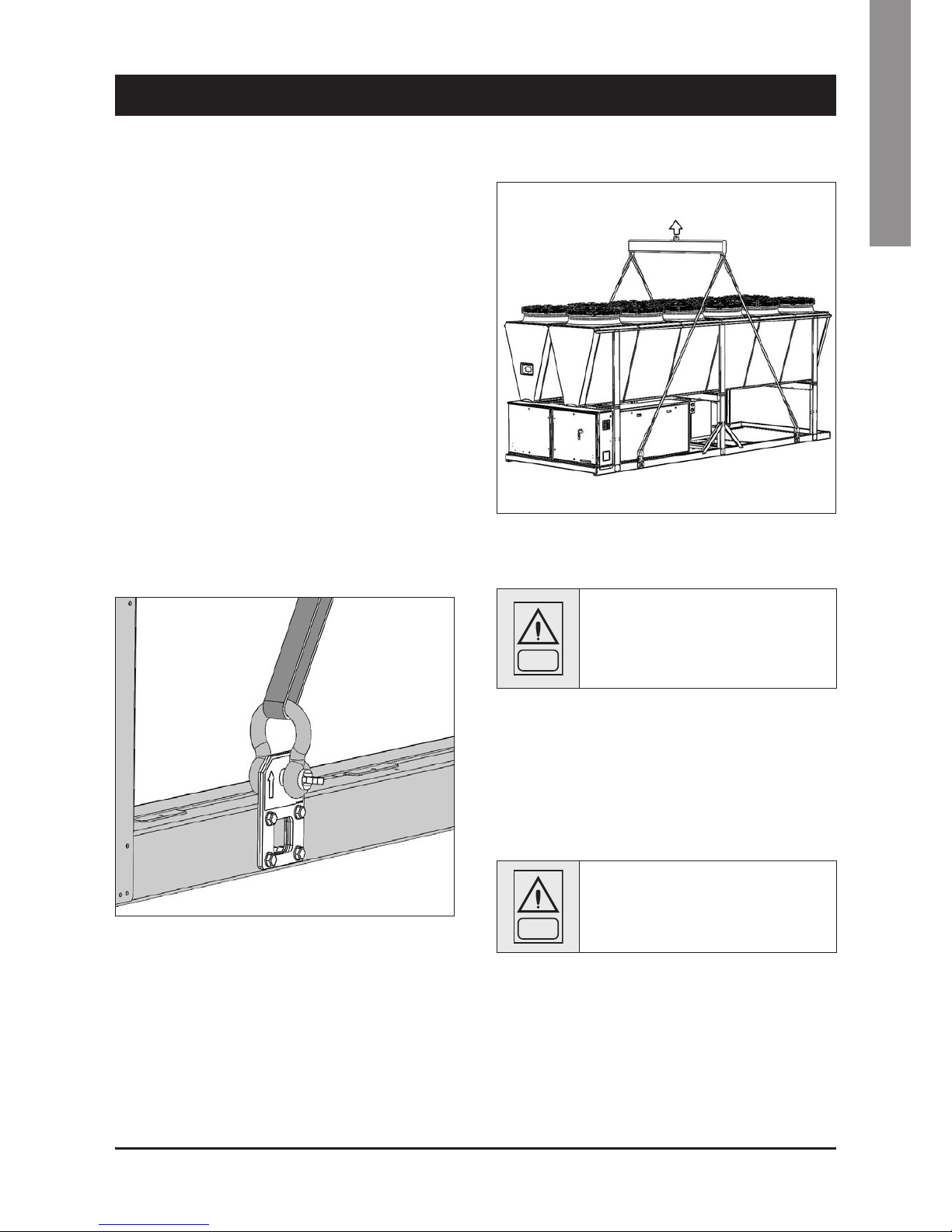
3.2 Lifting
The unit must be lifted by using the hooks inserted into the relevant
eyebolts (see the figure).
It is recommended to use a spacer to prevent cables from
damaging the unit (see the figure).
Before positioning the unit, make sure that the place of installation is
appropriate and sturdy enough to hold the weight and to withstand
the stress caused by the operation of the whole assembly.
WARNING
Do not displace the unit on rollers, and do not
lift it with a lift truck.
Unit must be lifted carefully.
To lift unit slowly and regularly.
To lift and displace the unit:
Q
Insert and secure eyebolts into the holes marked on the frame.
Q
Insert spacer between cables.
Q
Hook near the barycentre of the unit.
Q
The cables must be long enough to form, if tensioned, an angle
of at least 45° with respect to the horizontal plane.
WARNING
For lifting operations, use only tools and
material fit for this purpose, in accordance with
accident-prevention regulations.
Page 14

12
3 - Transport, Lifting and Positioning (continued)
WARNING
During the lifting and handling of the unit, be
careful not to damage the finned pack of the
coils positioned on the sides of the unit.
The sides of the unit must be protected by
cardboard or plywood sheets.
WARNING
It is recommended not to remove the protective
plastic envelope, that should prevent scraps
from penetrating into the appliance and any
damage to the surfaces, until the unit is ready
for operation.
WARNING
The lifting eyebolts protrude from the base
of the unit; it is therefore recommended to
remove them once the unit has been lifted and
positioned, if in your opinion they are likely to
become a source of hazard and injury.
The eyebolts must be mounted on the unit whenever it shall be
displaced and then lifted again.
3.3 Anchoring
It is not essential to secure the unit to the foundations, unless in
areas where there is a serious risk of earthquake, or if the appliance
is installed on the top of a steel frame.
3.4 Storage
When the unit is to be stored before installation, adopt a few
precautions to prevent any damage or risk of corrosion or wear:
Qplug or seal every single opening, such as water fittings
Qdo not store the appliance in a room where the temperature
exceeds 50 °C for the units using R410A and, if possible, do not
expose to direct sunlight
Qminimum storage temperature is -25 °C
Qit is recommended to store the unit in a roof where traffic is
minimized, to prevent the risk of accidental damage
Qthe unit must not be washed with a steam jet
Qtake away and leave to the site manager all the keys providing
access to the control board
Finally, it is recommended to carry out visual inspections at regular
intervals.
Page 15
13
English
4 - Installation
4.1 Positioning of the unit
DANGER
Before installing the unit, make sure that the
structure of the building and/or the supporting
surface can withstand the weight of the
appliance. The weights of the units are listed in
Chapter 8 of this manual.
These units have been designed for outdoor installation on a solid
surface. Standard accessories include antivibrating rubber supports,
that must be positioned under the base.
When the unit is to be installed on the ground, it is necessary to
provide a concrete base, to ensure a uniform distribution of the
weights.
As a general rule, no special sub-bases are required. However, if the
unit is to be installed on the top of inhabited rooms, it is advisable
to rest it on spring shock absorbers (optional), that will minimise the
transmission of any vibration to the structures.
To choose the place of installation of the unit, bear in mind that :
Qthe longitudinal axis of the unit must be parallel to the direction of
prevailing winds, so as to ensure a uniform distribution of the air
on finned exchangers
Qthe unit must not be installed near boilers’ vent pipes
Qthe unit must not be installed leeward with respect to sources of
air contaminated by greases, such as, for example, the outlets
to kitchen exhaust hoods into the atmosphere. Otherwise,
the grease is likely to deposit on the fins of the refrigerant /air
exchangers, and would fix every type of atmospheric impurity,
resulting in the quick clogging of the exchangers
Qthe unit must not be installed in areas subject to considerable
snow falling
Qthe unit must not be installed in areas subject to flooding, under
gutters etc.
Qthe unit must not be installed in air shafts, narrow courts or other
small places, where the noise may be reflected by the walls or
the air ejected by fans may short-circuit itself on refrigerant/air
heat exchangers or condenser
Qthe place of installation must be have all the necessary spaces
for air circulation and maintenance operations (see Chapter 8).
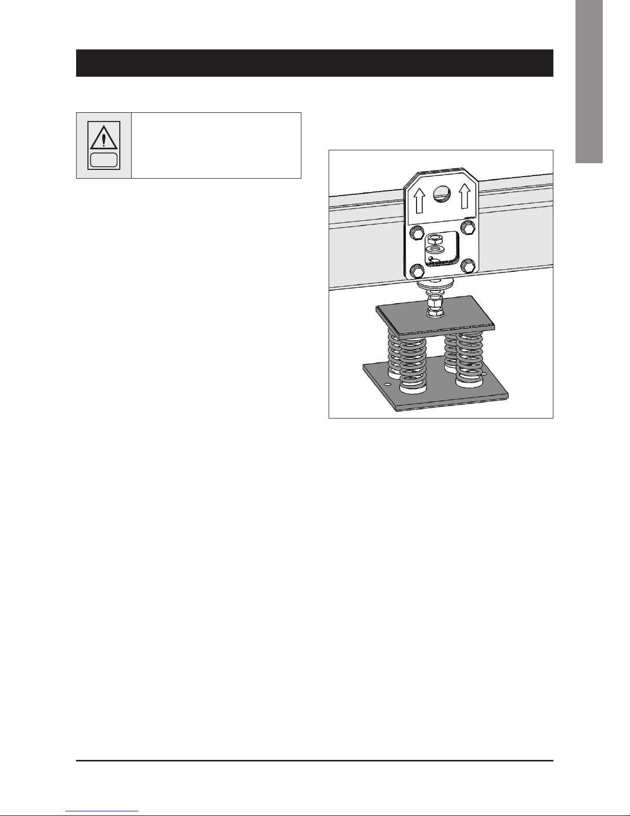
4.2 Spring Isolator Installation
Q
Prepare the base, that must be flat and plane.
Q
Lift the appliance and insert shock absorbers as follows:
Page 16
14
4 - Installation (continued)
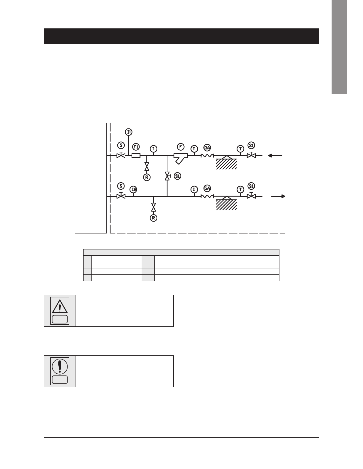
4.3 External Water Circuit
The flow switch and the filter water, although not included in the
supply, must always be fitted such as plant components. Their
installation is mandatory for warranty.
WARNING
The external hydraulic circuit must ensure the
water flow to the evaporator under any working
or adjustment conditions.
The circuit shall be composed by the following elements:
Q
A circulation pump which can ensure the necessary capacity
and discharge head.
Q
The capacity of the primary hydraulic circuit should not be less
than 2.4 litres/KW of cooling capacity, in order to prevent the
repeated start-up of the compressor and any damage to it. If
the water capacity in the primary piping of the circuit and in the
evaporator is lower than this value, an insulated storage tank
shall be installed.
Q
A membrane expansion vessel provided with safety valve with
vent, that must be visible.
NOTE
The capacity of the expansion vessel must allow
for an expansion of at least 2% of the volume of
the fluid in the circuit (evaporator, piping, user
circuit and standby tank, if any). The expansion
vessel needs not be isolated, because no water
can circulate inside it.
A flo w switch, to dis able the appliance when t he water is not
circulating.
WARNING
The flow switch must be connected (terminals
1-2) as s ho wn in the w ir ing diagram of the
“User’s Terminal Box” (Paragraph 4.7).
To install the flow switch, follow the manufacturer’s instructions.
As a general rule, the flow switch shall be mounted on a horizontal
pipe, at a distance from the curves equal to 10 times the diameter
of the pipe and far from valves or other components that are likely
to hinder the water flow upstream of or downstream from the flow
switch.
Q
The bleed valves must be mounted on the highest point of the
piping.
Q
The stop valves must be mounted on the piping of the water entering/leaving the condenser.
Q
The discharge points (provided with plugs, cocks etc.) must be
arranged in the lowest point of the piping.
Page 17
15
English
4 - Installation (continued)
Then:
Q
Provide the evaporator with a by-pass circuit equipped with a
valve to wash the plant.
Q
Insulate the piping, to prevent the risk of heat loss.
Q
Position a filter on the suction side of the evaporator of the heat
recovery condenser.
WARNING
Before filling the circuit, it is important to check
that it is free from any foreign matter, sand,
gravels, rust, welding deposits, waste and other
materials that may damage the evaporator.
When cleaning the lines, it is recommended to create a circuit bypass. It is important to mount a filtering medium (30 mesh) upstream
of the chiller.
NOTE
If necessary, the water required to fill the circuit
must be treated to obtain the requested PH.
If necessary, the water required to fill the circuit must be treated to
obtain the requested PH.
4.4 Hydraulic connection
The water inlet/outlet fittings shall conform to the instructions
provided by the plates affixed near the connection points.
4.5 Draining the defrosting waste water (for
heat pump unit only)
When heat pump units work in heating mode, during defrosting
cycles, they may discharge water from the base. This is why the
units should be installed at least 200 mm above the floor level, so
as to allow the free drainage of waste water, without the risk of
producing ice banks.
The heat pump units must be in stalled in positions whe re th e
defrosting water cannot create any damage.
Installation Flow Switch
External Hydraulic Circuit
Connection Diagram
Unit
COMPONENTS
I Pressure gauge connection R Drain cock
S Gate valve T Thermometer
F1 Flow Switch F Filter
GA Flexible hoses I1/I2 Pressure gauge connection to measure pressure drop or head pressure
Page 18
16
4 - Installation (continued)
4.6 Power supply
DANGER
Before carrying out any operations on the
electrical system, make sure that the unit is
deenergised.
DANGER
It is important that the appliance is grounded.
DANGER
The company in charge of the installation shall
conform to the standards applicable to outdoor
electrical connections.
The manufacturer may not be held liable for any damage and/or
injury caused by failure to comply with these precautions.
The unit conforms to EN 60204-1.
The following connections shall be provided:
QA 3-phase and grounding connection for the power supply
circuit.
QThe electrical distribution system shall meet the power absorbed
by the appliance.
QThe disconnecting and magnetothermal switches must be sized to
control the starting current of the unit.
QThe power supply lines and the insulation devices must be
designed in such a way that every line independent.
QIt is recommended to install differential switches, to prevent any
damage caused by phase drops.
QThe fans and compressors are supplied through contactors
controlled from the control panel.
QEach motor is provided with an internal safety thermal device
and external fuses.
QThe power supply cables must be inserted into dedicated
openings on the front of the unit, and the will enter the electrical
board through holes drilled on the bottom of the board.
4.7 Electrical connections
The unit must be installed on site according to the Machinery
Directive (2006/42/EC), the Low Voltage Directive (2006/95/EC),
the Electromagnetic Interference Directive (2004/108/EC) and
the usual procedures and standards applicable in the place of
installation.
The unit must not be operated if its installation has not been
carried out according to the instructions provided in this manual.
The power supply lines must consist of insulated copper
conductors, dimensioned for the maximum absorbed current.
Connection to terminals must be performed according to the diagram
of connections (User’s Terminal Box) provided in this manual and
according to the wiring diagram which accompanies the unit.
WARNING
Before connecting the power supply lines, check
that the available voltage value does not exceed
the range specified in the Electric Data (Chapter
8).
For 3-phase systems, check also that the unbalance between the
phases does not exceed 2%. To perform this check, measure the
differences between the voltage of each phase couple and their mean
value during operation.
The maximum % value of these differences (unbalance) must not
exceed 2% of the mean voltage.
If the unbalance is unacceptable, contact the Energy Distributor to
solve this problem.
WARNING
Supplying the unit through a line whose
unbalance exceeds the permissible value will
automatically void the warranty.
Page 19
17
English
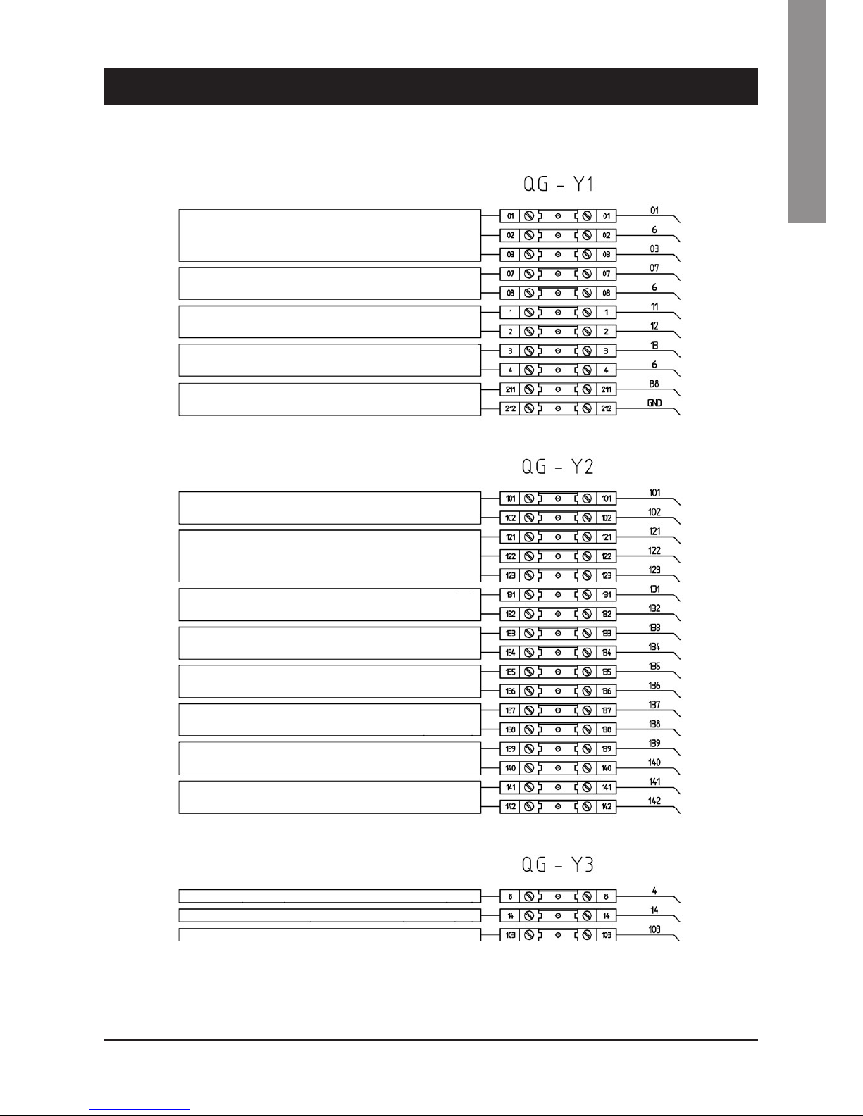
4 - Installation (continued)
REMOTE START/STOP SWITCH
(SRS)
(SDN)
(B8)
(NO)
(NO)
(NO)
(NO)
(NO)
(NO)
(NO)
(NO)
(NC)
(GND)
(COMMON)
(COMMON)
(COMMON)
(COMMON)
(COMMON)
(COMMON)
(COMMON)
(COMMON)
(SRHP)
(COMMON)
REMOTE SUMMER/WINTER SWITCH (ONLY HEAT PUMP)
DOUBLE SET-POINT (DAY/NIGHT)
EXTERNAL INTERLOCK (OPTIONAL) CIRC PUMP ETC
LAN WATER TEMPERATURE PROBE
REMOTE INDICATION VOLTAGE ON
REMOTE INDICATION COMPRESSOR 1 ON
REMOTE INDICATION COMPRESSOR 2 ON
REMOTE INDICATION COMPRESSOR 3 ON
REMOTE INDICATION COMPRESSOR 4 ON
REMOTE INDICATION COMPRESSOR 5 ON
REMOTE INDICATION COMPRESSOR 6 ON
GENERAL ALARM SYSTEM 1-2
FLOW SWITCH (SF)
COMMON (COM)
ANTIFREEZE RELAY CONTROL (NO)
PUMP RELAY CONTROL (NO)
AQWL/AQWH - Electrical connections
Page 20
18
4 - Installation (continued)
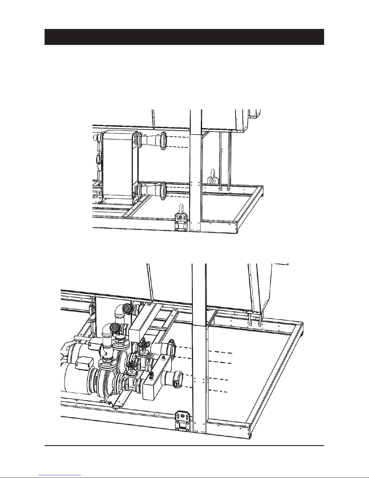
4.8 Connecting plate-type evaporator
temperature sensors
AQWL, AQWH and AQWR units are provided with fittings for hydraulic
connections between heat exchangers and plant.
Water connection units with pump(s)
Each fittings is complete with sensor well to fasten temperature
sensor (BT-IN and BT-OUT). Fittings are supplied separate and must
be mounted during the installation of the unit.
Page 21

19
English
4 - Installation (continued)
4.9 Total heat recovery features
Temperature sensors
Temperature sensors for recovery system water control, BTRin e
BTRout, are supplied by factory with the unit, already wired, and
must be fitted on the water connections at the heat reclaim condenser inlet and outlet (see wiring diagram).
Three-way valve
The three-way valve must be installed on-site. It permits bypassing
the heat reclaim condenser for correct operation at low return water
temperature. Water and electrical connections, as well as thermal
insulation must be made at the time of installation on-site.
The best position is close to heat reclaim condenser (to achieve a
small water circuit).
NOTE: The space required by this valve does not permit installation
on the factory.
Water connection units with pump and buffer tank
Forced shuttering
When recovery system is on, a commutation from air condensing
and water condensing takes place.
At the same time compressor-tandem is automatically shuttered to
allow the control of condensation in the transient phase. The same
process takes place when the system commutates from water condensing to air condensing.
Page 22

20
5 - Start-Up
WARNING
The unit must be started for the first time by
personnel suitably trained by one Authorised
Service Centre. Failure to meet this requirement
will immediately void the warranty.
NOTE
The operations carried out by authorised
personnel are limited to the star t-up of the unit,
and do not include any other operation on the
plant, such as, for example, electrical and
hydraulic connections etc.
All the other operations before start-up, including
oil pre-heating for at least 12 hours, must be
performed by the Installer.
5.1 Preliminary check
The checks listed below shall be performed before starting the unit
and before the arrival of the personnel authorised.
QCheck the section of power supply and grounding cables; make
sure that terminals are tightened and check the correct operation
of contactors, with the main switch open.
QCheck that any voltage and phase variation in the power supply
does not exceed the prefixed thresholds.
QConnect the contacts of the flow switch and the thermal relay of
the pump and of the other devices (if any), to terminals 1-2 and
3-4, respectively.
QCheck that the components of the external water circuit (pump,
user equipment, filters, power supply tank and reservoir, if any)
have been installed properly, and according to the manufacturer’s
instructions.
QCheck the filling of the hydraulic circuits, and make sure that
the fluid circulation is correct, without any trace of leaks and air
bubbles. If you use ethylene glycol as antifreeze, check that its
percentage is correct.
QCheck that the direction of rotation of the pumps is correct, and
that fluids have been circulating for at least 12 hours for both
pumps. Then, clean the filters on the suction side of the pumps.
QAdjust the liquid distribution network in such a way that the flow
rate is within the specified range.
QCheck that the water quality is up to the specifications.
QCheck that oil heaters, if any, have been turned on at least 12
hours before.
5.2 Start-up
Start-up sequence:
QTurn on the Main switch (at least 12 hours before).
QCheck that the oil in the compressor has reached the requested
temperature (the minimum temperature outside the pan must be
approx. 40°C) and that the auxiliary control circuit is energised.
QCheck the operation of all the external equipment, and make sure
that the control devices of the plant are properly calibrated.
QStart the pump and check that the water flow is correct.
QSet the desired fluid temperature on the control board.
QStart the appliance (see Chapter 6).
QCheck the correct direction of rotation of compressors. Scroll
compressors cannot compress the refrigerant when they rotate
in the opposite direction. To make sure that they are rotating in
the correct direction, simply check that, just after the start-up
of the compressor, the pressure drops on the LP side and rises
on the HP side. Furthermore, if a scroll compressor rotate in
the opposite direction, there is a considerable rise in the sound
level of the unit, as well as in a dramatic reduction of current
absorption compared to normal values. In case of wrong
rotation, the scroll compressor can be definitely damaged. Phase
monitor is assembled in the unit as a standard to prevent wrong
compressors rotation.
QAfter about 15 minutes of operation check that there are no
bubbles, through the sight glass on the liquid line.
WARNING
The presence of bubbles may indicate that a
part of the refrigerant charge has been released
in one or more points. It is important to remove
these leaks before proceeding.
QRepeat the start-up procedure after removing the leaks.
QCheck the oil level in the compressor’s sight glass.
5.3 Checking the operation
Check the following:
QThe temperature of the water entering the evaporator.
QThe temperature of the water leaving the evaporator.
QThe level of the water flow rate in the evaporator, if possible.
QThe current absorption upon the start of the compressor and in
case of stabilised operation.
QThe fan’s current absorption.
Check that the condensing and evaporation temperatures, during
operation at high and low pressure detected by the pressure gauges
of the refrigerant, are within the following range:
(On the units not provided with HP/LP pressure gauges for the
refrigerant, connect a pressure gauge to the Shrader valves on the
refrigeration circuit).
HP side
Approx. 15 to 21 °C above the temperature of
the air entering the condenser, for R410A units.
LP side
Approx. 2 to 4 °C below the temperature of the
leaving chilled water, for R410A units.
5.4 Delivery to the customer
QTrain the user according to the instructions provided in Section 6.
Page 23

21
English
6 - Control
General information
Introduction
This document contains the information and the operating
instructions for the units.
This information is for the after-sales service and the production
operators, for the end-of-line testing.
Main characteristics
– Microprocessor control
– User-friendly keyboard
– Proportional and integral control of the return
water temperature (RWT)
– Hysteresis control of the leaving water
temperature (LWT)
– Access code to enter the Manufacturer’s Level
– Access code to enter the Assistance Level
– Alarm and LED
– Backlighted LCD
– Closed-loop condensing pressure control
– Pump-Down logic (start-stop)
– Rotation of the compressor operation
– Oil return function
– Night mode (or Low Noise) control
– Counting of the pump/compressors’ hours of
operation
– Display and control of superheating by EEV
– Display of discharge and suction pressure values
– History of stored alarms (option)
– Programming of different setpoints with 4 ranges
of time/setpoint.
The following accessories can be also connected:
– Real Time Clock Memory Card: alarm history and programming of
different setpoints with ranges of time
– serial communication RS485 card; to connect the “Chiller
Control” to a BMS network
– remote display terminal
– wire remote control.
6.1 The "CHILLER CONTROL" system
Units are provided with a microprocessor card which is fully
programmed in factory for the control of a chiller with 2 circuits,
2/3 compressors per circuit, a high-pressure transducer and an
electronic expansion valve per circuit.
Keyboard & Display Terminal
General information
The figure shows the terminal with the front door open.
It is provided with a LCD 4 lines x 20 columns, keyboard and
microprocessor-controlled LED’s, so as to allow the programming of
the control parameters (setpoint, differential bands, alarm thresholds)
and themain operations to be carried out by the user.
Terminal & Key Board description
The terminal makes it possible to carry out the following operations:
– the initial configuration of the machine
– the change of all the main operating parameters
– the display of the detected alarms
– the display of all the measured quantities
The terminal and the card are connected by a 6-way phone cable.
The connection of the terminal to the basic card is not essential for
the normal operation of the controller.
Page 24

22
6.2 Display
The display is an LCD 4 lines x 20 columns. The quantities and the
information about the operation of the unit are alternated in the form
of subsequent screens, named.
x
Home
Line 0
Line 1
Line 2
Line 3
6.3 Keyboard
Arrows key - Up/Down/Enter
If the cursor is in the top left-hand corner (Home), press the UP/
DOWN keys to access the subsequent masks associated to the
selected branch. If a mask includes some value setting fields and
you press the ENTER key, the cursor will reach these fields.
Once you have reached the quantity setting field, you can modify any
value (within the expected limits) by pressing the UP/DOWN keys.
After you have selected the desired value, press the ENTER key again
to store it.
6 - Control (continued)
Access to the “display mask” of the machine status.
Esc key: allows you to move from one mask to another.
Alarm key: used to display the alarms, to reset them in
manual. Press it one to display the mask of the activated
alarm, press it again to reset the alarm signal.
+
Prg+Esc keys: pressing these keys at the same time,
allows you to turn the unit On/Off.
Up-down keys: allows you to set the control parameters’
values and to move from one mask to another (not
backlighted).
Enter key: used to move the cursor inside the masks and
to save the values of the set parameters.
+
Alarm+Enter keys: press these keys at the same time
to enter the “storical alarm” after 1’ come back at status
machine menu.
User
Manufactured
Maintenance
In/Out
Setpoint
Release
On/Off
Daily time zone
Page 25

23
English
6 - Control (continued)
Alarms
Alarm Description
Comp SYS 1
Status
Comp SYS 2
Status
Fan SYS 1
Status
Fan SYS 2
Status
Pump
Status
Reset
Auto/Man
AL01 Power supply wrong OFF OFF OFF OFF OFF MAN
AL02 Antifreeze alarm OFF OFF OFF OFF OFF MAN
AL03 Interlock OFF OFF OFF OFF OFF MAN
AL04 Lack of flow OFF OFF OFF OFF OFF MAN
AL05 SYS #1 Low suction pressure OFF ON OFF ON ON MAN
AL06 SYS #2 Low suction pressure ON OFF ON OFF ON MAN
AL07 SYS #1 High pressure supply OFF ON OFF ON ON MAN
AL08 SYS #2 High pressure supply ON OFF ON OFF ON MAN
AL91 SYS #2 Thermal compressor 1 OFF COMP1 ON ON ON ON MAN
AL92 SYS #2 Thermal compressor 2 OFF COMP2 ON ON ON ON MAN
AL93 SYS #2 Thermal compressor 3 OFF COMP3 ON ON ON ON MAN
AL101 SYS #1 Thermal compressor 1 ON OFF COMP1 ON ON ON MAN
AL102 SYS #1 Thermal compressor 2 ON OFF COMP2 ON ON ON MAN
AL103 SYS #1 Thermal compressor 3 ON OFF COMP3 ON ON ON MAN
AL11 Recovery antifreeze alarm Recovery disabled
AL141 SYS #1 Thermal cond.fans1 OFF ON OFF ON ON MAN
AL142 SYS #1 Thermal cond.fans2 OFF ON OFF ON ON MAN
AL151 SYS #2 Thermal cond.fans1 ON OFF OFF ON ON MAN
AL152 SYS #2 Thermal cond.fans2 ON OFF OFF ON ON MAN
AL16 SYS #1 Compressor diff.press.alarm OFF ON OFF ON ON MAN
AL17 SYS #2 Compressor diff.press.alarm ON OFF ON OFF ON MAN
AL21 Remote setpoint out of range OFF OFF OFF OFF OFF MAN
AL22 Press.suction SYS1 Sensoralarm OFF ON OFF ON ON MAN
AL23 Press.discharge SYS1 Sensoralarm OFF ON OFF ON ON MAN
AL24 Temp.Return Water Damaged Sensor OFF OFF OFF OFF OFF MAN
AL25 Temp Leaving Water Damaged Sensor OFF OFF OFF OFF OFF MAN
AL26 Press Suction SYS2 Sensoralarm ON OFF ON OFF ON MAN
AL27 Press.Discharge SYS2 Sensoralarm ON OFF ON OFF ON MAN
AL28 Temperatur Chill.net Sensoralarm OFF OFF OFF OFF OFF MAN
AL29 Temperatur Coil SYS1 Sensoralarm OFF ON OFF ON ON MAN
AL30 Temperatur Coil SYS2 Sensoralarm ON OFF ON OFF ON MAN
AL301 Outdoor Air Temper. Sensoralarm OFF OFF OFF OFF OFF MAN
AL302 Temp.Discharge SYS1 Sensoralarm OFF ON OFF ON ON MAN
AL303 Temp.Discharge SYS2 Sensoralarm ON OFF ON OFF ON MAN
AL304 Temp.Return Recovery Sensoralarm OFF OFF OFF OFF OFF MAN
AL305 Temp Leaving Recovery Sensoralarm OFF OFF OFF OFF OFF MAN
AL311 SYS #1 compressor 1 maintenance ON ON ON ON ON MAN
AL312 SYS #1 compressor 2 maintenance ON ON ON ON ON MAN
AL313 SYS #1 compressor 3 maintenance ON ON ON ON ON MAN
AL321 SYS #2 compressor 1 maintenance ON ON ON ON ON MAN
AL322 SYS #2 compressor 2 maintenance ON ON ON ON ON MAN
AL323 SYS #2 compressor 3 maintenance ON ON ON ON ON MAN
AL33 Evaporator Pump Maintenance ON ON ON ON ON MAN
AL37 pCO Eeprom broken OFF OFF OFF OFF OFF MAN
AL44 pCOe disconnected ON ON ON ON ON MAN
AL45 Analog input probe channel 1 broken OFF OFF OFF OFF OFF MAN
AL46 Analog input probe channel 2 broken OFF OFF OFF OFF OFF MAN
AL47 Analog input probe channel 3 broken OFF OFF OFF OFF OFF MAN
AL48 Analog input probe channel 4 broken OFF OFF OFF OFF
OFF MAN
AL50 EVD Eeprom error OFF OFF OFF OFF OFF MAN
AL51 EEV Motor error (check wirings) SYS1 OFF ON OFF ON ON MAN
AL52 MOP timeout (check timeout) SYS1 OFF ON OFF ON ON MAN
AL53 LOP timeout (check timeout) SYS1 OFF ON OFF ON ON MAN
AL54 Low SuperHeat (check timeout) OFF ON OFF ON ON MAN
Page 26

24
Setpoint
Pressing the Set key allows you to enter the Set point level accessible to the user. The parameters that can be set are listed below, along with the
limit values and the default values (standard shop settings):
Each alarm is memorized in alarm history. If it is of manual reset type, its code is indicated in previous table. On the other hand, if it is of automatic
reset type, it is recorded with a special code as shown in table below:
User parameters Control mode Min value Max value Default
Cooling Setpoint
RWT Return Control 8 20 10
LWT Leaving Control 6 20 8
Cooling Setpoint - glycol water
RWT Return Control -15 20 10
LWT Leaving Control -15 20 8
Proportional band RWT Return Control 1 10 5
Neutral band LWT Leaving Control 1 6 2
Heating Setpoint
RWT Return Control 20 45 40
LWT Leaving Control 20 50 40
Languages —— ITA ENG FRE GER SPA ITA
System On/Off
System 1 # —— OFF ON OFF
System 2 # —— OFF ON OFF
Unit management Cooling Heating
6 - Control (continued)
Alarm Description
Comp SYS 1
Status
Comp SYS 2
Status
Fan SYS 1
Status
Fan SYS 2
Status
Pump
Status
Reset
Auto/Man
AL55 Low suction alarm SYS 1 OFF ON OFF ON ON MAN
AL58 S1 sensor fault OFF ON OFF ON ON MAN
AL59 S2 sensor fault OFF ON OFF ON ON MAN
AL61 EVD Lan disconnected OFF OFF OFF OFF OFF MAN
AL62 Regulation alarm SYS 1 OFF ON OFF ON ON MAN
AL63 Autotune alarm SYS 1 OFF ON OFF ON ON MAN
AL64 EEV Motor error (check wirings) ON OFF ON OFF ON MAN
AL65 MOP timeout (check timeout) ON OFF ON OFF ON MAN
AL66 LOP timeout (check timeout) ON OFF ON OFF ON MAN
AL67 Low SuperHeat (check timeout) ON OFF ON OFF ON MAN
AL68 Low suction alarm SYS 2 ON OFF ON OFF ON MAN
AL69 Battery alarm OFF OFF OFF OFF OFF MAN
AL71 S3 sensor fault ON OFF ON OFF ON MAN
AL72 S4 sensor fault ON OFF ON OFF ON MAN
AL74 Regulation alarm SYS 2 ON OFF ON OFF ON MAN
AL75 Autotune alarm SYS 2 ON OFF ON OFF ON MAN
Alarm description Manual reset code Auto reset code
Lack of flow AL04 AL904
SYS#1 low suction pressure AL05 AL905
SYS#2 low suction pressure AL06 AL906
SYS#1 high pressure supply AL07 AL907
SYS#2 high pressure supply AL08 AL908
SYS#2 thermal compressor 1 AL91 AL901
SYS#2 thermal compressor 2 AL92 AL902
SYS#2 thermal compressor 3 AL93 AL903
SYS#1 thermal compressor 1 AL101 AL991
SYS#1 thermal compressor 2 AL102 AL992
SYS#1 thermal compressor 3 AL103 AL993
Page 27

25
English
Compressor protection
Compressors are equipped with a heating element to prevent
oil dilution, which may result in remarkable risks of failure of
compressors.
The windings of the compressors’ motors are provided with a
thermal protection.
For AQW models an accessory kit for thermal protection is available,
for any overcurrent of scroll compressors, which shall be shopmounted.
Electrical flow switch
To ensure the correct operation of the unit, a electrical flow switch
must be installed, to prevent the unit working in case of insufficient
circulation of the chilled fluid.
WARNING
The electrical flow switch must be carefully
installed, according to the instructions given by
the Manufacturer.
The electrical flow switch must be installed on the pressing side
of the circulation pump for the fluid, just upstream of the heat
exchanger’s inlet. The electrical flow switch must be installed in a
horizontal straight length of piping, in a position reasonably far (both
upstream and downstream) from localized pressure drops (curves,
valves etc.).
Continuous Regulation of the Fan Speed
The fans’ speed regulator, if installed, allows the unit to work at an
ambient temperature down to -18 °C.
Differential pressure switch
This pressure switch halts the operation of the unit in the event that
it does not detect a sufficient pressure drop through the exchanger.
6.4 Protection and Safety Equipment
Defrosting System (only for AQWH models)
The AQWH units are provided with an automatic defrosting system,
which prevents the formation of excessive ice banks on coolant/air
exchangers during heat pump operation.
This system, which is part of the electronic control system, is of the
time/suction pressure type, and when the suction pressure detected
by a sensor drops below a fixed limit, once the preset time is over,
switches from heating to cooling the operation of the unit, with the
fans stopped.
During the defrosting cycle the compressor works normally, but the
coil’s fans remain off. The defrosting cycle stops after the coil has
been defrosted, and at this point the unit can work in heating mode
again.
NOTE
For safety purposes, fans are started also during
defrosting, if the discharge pressure reaches
considerable values.
Frost Protection for the Chilled Fluid
These units are provided with frost protection for the chilled fluid. This
protection consists of an electrical resistor positioned in contact with
the coolant/circulating fluid exchanger, which is activated (although
the unit is off) when the temperature of the fluid drops below 5 °C the standard value for a non-glycol unit.
If the leaving water temperature drops below 4 °C (standard value for
a non-glycol unit) the machine’s antifreeze alarm is activated. If the
circulating fluid is water, before the beginning of the cold season it is
advisable to drain the circuit to prevent water frosting.
If the circuit cannot be drained, it is essential to avoid de-energizing
the unit, so as to permit the activation, when necessary, of the frost
protection.
6 - Control (continued)
Page 28

26
6 - Control (continued)
6.5 HPF version configuration
Units equipped with special brushless fans (HPF) can be set-up on the field to give the unit a specific static pressure.
By entering parameter in service level - Max Speed (Vdc) - it is possible to modify high static pressure.
The table below shows the correspondance between chiller model, fan RPM, high static pressure.
Sizes Fan Static Pressure (Pa) Fan rpm
Parameter in Service Level
Max Speed (Vdc)
1404
40 900 8.3
60 930 8.5
80 970 8.8
100 1000 9.1
120 1030 9.3
1604
40 900 8.2
60 930 8.5
80 970 8.8
100 1000 9.1
120 1030 9.3
1806
40 900 8.3
60 930 8.5
80 970 8.8
100 1000 9.1
120 1030 9.3
2106
40 900 8.3
60 940 8.6
80 970 8.8
100 1000 9.1
120 1040 9.4
2406
40 1010 9.1
60 1040 9.4
80 1080 9.7
100 1100 9.8
120 1130 10.0
Note: Values in bold are standard factory settings.
Page 29

27
English
7 - Product Description
7.1 Introduction
AQW units are water chillers /air-water heat pumps provided with
hermetic scroll compressors with two refrigeration circuits.
These units are fit for cooling and heating intermediate fluids (glycoled
water), for air-conditioning applications in industrial processes.
These units can be installed outdoor on the roof of a building or at
ground level.
This series includes the following versions:
7.2 General specifications
AQW units are supplied complete and provided with all connecting
pipes for the refrigerant and internal wiring.
The refrigeration circuit of each unit undergoes a pressure test, is
drained, vacuumised, dehydrated and filled with refrigerant, and
includes the necessary oil. Once assembled, each unit is subjected
to a complete final testing and the correct operation of all refrigeration
circuits is checked.
The base and the frame of each unit are made of very thick
galvanised sheet, and are secured by screw and stainless bolts. All
panels are secured by screw and tropicalised steel bolts, they can be
disassembled for easy access to internal components.
All galvanised steel parts are painted with white polyester resin
(RAL 9001), to ensure the resistance of the unit to corrosion and
weather agents over time.
7.3 Compressors
These units are provided with hermetic scroll compressors, with
built-in motor protection.
Compressors are mounted on shock absorbers to reduce vibrations.
Motors are of direct start-up type, cooled by the sucked refrigerant
gas.
Thermistors protect the windings from any over temperatures and the
electronic control checks that the delivery temperature is within the
permissible range.
The capacity control, as well as the control of the delivered cooling
capacity, are always ensured by the electronic control.
7.4 Refrigeration circuits
Each unit has two complete refrigeration circuits, including: a service
valve to fill the unit with refrigerant, shut-off valves, thermostatic
expansion valve, dehydrating filter, sight glass with humidity indicator,
a differential pressure switch for the water.
The outdoor AQWC units, deriving from the AQWL versions, are
marked by the absence of the evaporator, and are equipped with
shutoff cocks on the suction line and on the liquid line, so as to allow
the connection of remote evaporators.
Furthermore, each circuit is equipped with safety devices in
accordance with PED 97/23/EC: HP and LP pressure switches,
safety valves providing protection in case of fire or malfunction of
compressors.
7.5 Water heat exchanger
The evaporators are of stainless steel plate type.
Their thermal insulation is ensured by a thick flexible closed-cell
heat-insulating jacket. Furthermore, the frost protection is ensured
by electric heaters.
These exchangers can work at pressures up to 10 bar on the
hydraulic side and 45 bar on the refrigerant side.
The hydraulic connections to the evaporator are of 3” Victaulic type.
7.6 Air heat exchanger
Coils are made of copper pipes in staggered rows, mechanically
expanded inside an aluminium finned pack.
7.7 Fans
Fans are of directly coupling propeller type, provided with aluminium
blade with wing profile.
Each fan is provided with galvanised steel accidentprevention guard.
Finally, motors are completely closed, protection class IP54,
protection thermostat immersed in windings.
VERSION (STD/HSE) (1) DESCRIPTION
Base Low Noise version (BLN) (2)
Air condensing chillers/heat pumps, using R410A refrigerant.
Low Noise version (LN)
Extra Low Noise version (ELN)
High Temperature version (HT)
OPTIONS DESCRIPTION
AQWL/D
The heat recovery is carried out by a desuperheater mounted on the compressor’s discharge line.
AQWH/D
AQWR
Total heat recovery is carried out by a heat exchanger mounted on the compressor’s discharge line in parallel with
the condensing circuit. Heat recovery function is activated by mean of a 4-ways valve.
(1) High efficiency units (HSE) with brushless fans (2) A high pressure fan (HPF) version is available
For each AQW version, the corresponding condensing unit version (AQWC) is available.
Available options:
Page 30

28
7 - Product Description (continued)
7.8 Electric power supply and control system
The control compartment contains and electronic card with keyboard
and a display for working parameters, alarms, if any, and operating
blocks.
It is complete with remote control switches and protection fuses for
the motors of compressors, fans and pumps.
7.9 Accessories
List of available accessories, provided separately, to be mounted on
site by the installer:
Water flow switch
Prevents the operation of the unit when the chilled fluid is insufficient.
It is advisable to install a flow switch, to ensure the correct operation
of the unit.
Water filter
Filter to be mounted on the suction side of the water heat exchanger.
Antivibrating supports (AVM)
Isolating spring supports, equipped with bolts for fastening to
the base. They are supplied separated from the unit and must be
mounted on site by the customer, at his own expense.
Fan speed regulator
The speed regulator of the fans is mounted as a standard accessory
for the Extra Low Noise units, and is an optional accessory for the
Standard and Low Noise units. The fan speed is controlled in order to
work at a low room temperature, and allows the unit to work down to
a room temperature of -18 °C.
The control can be of the pressostatic step type, with temperature
correction, or of continuous type (under pressure), with electronic
regulator. The regulator is of electronic type only for the Extra Low
Noise versions.
Wire-type remote control kit
The kit includes a remote control for wall mounting, complete with
3m-long connecting cable, and installation manual and a transformer.
For longer distances (i.e. up to 50m) you can use a multipolar cable
of minimum section (0.25mm). Conductors should be connected
directly and according to the diagram with accompanies the
installation instructions.
Remote wall terminal
Makes it possible to check the unit through a remote terminal, up to
a maximum distance of 200 meters.
RS-485 serial card (for MODBUS or LONWORK or BACNET)
A communication interface makes it possible to control and manage
the unit from a local station, with RS485 connection, up to a distance
of 1000 m.
It is possible to obtain the remote control and the management, by
inserting the control into the management plant of the building.
Page 31

29
English
7 - Product Description (continued)
SAFETY / CONTROL DEVICES HAZARD CATEGORY / EVALUATION MODULE
A High pressure switch (40.5 bar) 4/mod. B+D
AT High pressure transducer
BT Low pressure transducer
C Water differential pressure switch (105 mbar)
D Air temperature sensor
E Outlet water temperature sensor
F Inlet water temperature sensor
G PED pressure relief valve (45 bar) 4/mod. H1 (4/mod. D)
S 5/16” shrader connection (service only)
Pipe connection with shrader valve
COMPONENTS VESSEL CATEGORY (2) / EVALUATION MODULE
1 Tandem or trio Scroll type compressors 2/mod. D1
2 Air cooled condenser
3 Filter drier
4 Electronic expansion valve
5 Globe valve
6 Plate heat exchanger (Dual type) 2-3/mod. B+D
7 Desuperheater (optional)
Note: For reasons of readability, one circuit only is shown. The second circuit is identical.
5
1
D
2
3
4
5
6
BT
C
E
F
G
7
EXV
CONTROL
UNIT
CONTROL
S
S
AT
A
A
S
Refrigerant flow diagram - AQWL units
Page 32

30
7 - Product Description (continued)
Refrigerant flow diagram - AQWH units
SAFETY / CONTROL DEVICES HAZARD CATEGORY / EVALUATION MODULE
A High pressure switch (40.5 bar) 4/mod. B+D
AT High pressure transducer
BT Low pressure transducer
C Water differential pressure switch (105 mbar)
D Air temperature sensor
E Outlet water temperature sensor
F Inlet water temperature sensor
G PED pressure relief valve (45 bar) 4/mod. H1 (4/mod. D)
H Defrost temperature sensor
S 5/16” shrader connection (service only)
Pipe connection with shrader valve
COMPONENTS VESSEL CATEGORY (2) / EVALUATION MODULE
1 Tandem or trio Scroll type compressors 2/mod. D1
2 Air cooled condenser
3 Filter drier
4 Electronic expansion valve
5 Globe valve
6 Check valve
7 Liquid receiver 3/mod. B+D
8 Four-way valve
9 Suction accumulator 2/mod. D1
10 Sight glass
11 Plate heat exchanger (Dual type) 2-3/mod B+D
12 Desuperheater (optional)
Note: For reasons of readability, one circuit only is shown. The second circuit is identical.
G
F
E
ON
C
A
BT
1
6
6
5
5
8
9
7
11
6
6
3
12
2
D
H
A
S
AT
S
G
4
EXV
CONTROL
UNIT
CONTROL
5
10
Page 33

31
English
7 - Product Description (continued)
Refrigerant flow diagram - AQWR units
H
D
3
4
5
7
10
8
G
66
6
BT
ON
A
A
AT
9
G
2
5
EXV
CONTROL
UNIT
CONTROL
S
S
S
F
E
C
1
SAFETY / CONTROL DEVICES HAZARD CATEGORY / EVALUATION MODULE
A High pressure switch (40.5 bar) 4/mod B+D
AT High pressure transducer
BT Low pressure transducer
C Water differential pressure switch (105 mbar)
D Air temperature sensor
E Outlet water temperature sensor
F Inlet water temperature sensor
G PED pressure relief valve (45 bar) 4/mod H1/(4/mod. D)
H Defrost temperature sensor
S 5/16” shrader connection (service only)
Pipe connection with shrader valve
COMPONENTS VESSEL CATEGORY (2) / EVALUATION MODULE
1 Tandem or trio Scroll type compressors 2/mod. D1
2 Air cooled condenser
3 Filter drier
4 Electronic expansion valve
5 Globe valve
6 Check valve
7 Liquid receiver 3/mod. B+D
8 Four-way valve
9 Heat recover (dual type) 2-3/mod B+D
10 Heat exchange (dual type) 2-3/mod B+D
Note: For reasons of readability, one circuit only is shown. The second circuit is identical.
Page 34

32
7 - Product Description (continued)
SAFETY / CONTROL DEVICES HAZARD CATEGORY / EVALUATION MODULE
A High pressure switch (40.5 bar) 4/mod B+D
AT High pressure transducer
BT Low pressure transducer
D Air temperature sensor
G PED pressure relief valve (45 bar) 4/mod. H1 (4/mod D)
S 5/16” shrader connection (service only)
Pipe connection with shrader valve
COMPONENTS VESSEL CATEGORY (2) / EVALUATION MODULE
1 Tandem or trio Scroll type compressors 2/mod D1
2 Air cooled condenser
3 Globe valve
Note: For reasons of readability, one circuit only is shown. The second circuit is identical.
AT
3
A
D
2
A
G
BT
3
3
S
S
S
1
Refrigerant flow diagram - AQWC units
Page 35

33
English
8.1 Pressure drops
8 - Technical Data
PRESSURE DROP IN THE EVAPORATOR *
1404 1604 1806 2106 2406
K kPa/(l/h)^2 1.18 x 10
-8
9.51 x 10
-9
7.56 x 10
-9
7.56 x 10
-9
6.42 x 10
-9
Minimum flow rate l/h 40850 45462 53320 60415 68198
Nominal flow rate l/h 65360 72739 85312 96664 109117
Maximum flow rate l/h 108933 121231 142187 161107 181861
Minimum pressure drop kPa 19.7 19.7 21.5 27.6 29.9
Nominal pressure drop kPa 50.4 50.3 55.0 70.6 76.4
Maximum pressure drop kPa 140.0 139.8 152.8 196.2 212.3
PRESSURE DROP IN THE HEAT RECOVERY CONDENSER *
1404 1604 1806 2106 2406
K kPa/(l/h)^2 1.18 x 10
-8
9.51 x 10
-9
7.56 x 10
-9
7.56 x 10
-9
6.42 x 10
-9
Minimum flow rate l/h 52568 58695 68693 78045 87935
Nominal flow rate l/h 84108 93912 109908 124872 140696
Maximum flow rate l/h 140180 156520 183180 208120 234493
Minimum pressure drop kPa 32.6 32.8 35.7 46.0 49.6
Nominal pressure drop kPa 83.5 83.9 91.3 117.9 127.1
Maximum pressure drop kPa 231.9 233.0 253.7 327.5 353.0
PRESSURE DROP IN THE DESUPERHEATER *
1404 1604 1806 2106 2406
K kPa/(l/h)^2 7.720 x 10
-7
5.009 x 10
-7
5.009 x 10
-7
3.200 x 10
-7
3.200 x 10
-7
Minimum flow rate l/h 5268 5913 6880 7848 8815
Nominal flow rate l/h 8428 9460 11008 12556 14104
Maximum flow rate l/h 14047 15767 18347 20927 23507
Minimum pressure drop kPa 21.4 17.5 23.7 19.7 24.9
Nominal pressure drop kPa 54.8 44.8 60.7 50.4 63.7
Maximum pressure drop kPa 152.3 124.5 168.6 140.1 176.8
¨3 .
.
Q
2
* Data refer to BLN version
¨3 .
.
Q
2
* Data refer to BLN version
¨3 .
.
Q
2
* Data refer to BLN version and to one condenser only
Page 36

34
8 - Technical Data (continued)
8.2 Technical data
(1) Sound levels are at fully loaded conditions. Sound power level values refer to ISO standard 3744 and Eurovent 8/1.
(2) Sound pressure levels refer to ISO standard 3744, parallelepiped shape.
(*) High efficiency units (HSE) with inverter fans.
(**) HPF units with high static pressure fans.
Note: Refrigerant charge data are indicative only. Always refer to data shown on the unit nameplate.
AQWL STD/HSE/HPF - BLN models 1404 1604 1806 2106 2406
Power supply V/Ph/Hz 400 (±10%)/3/50
Number of refrigerant circuits 2 2 2 2 2
Refrigerant charge kg 40 + 40 44 + 44 52 + 52 67 + 52 67 + 67
Total capacity steps % 21-50-71-100 25-50-75-100 17-33-50-67-83-100 15-29-43-62-81-100 17-33-50-67-83-100
COMPRESSORS
Number 4 4 6 6 6
Type Scroll
Oil type POE
N° of loading stages 0/100 0/100 0/100 0/100 0/100
EVAPORATOR
Number 1 1 1 1 1
Type PLATE PLATE PLATE PLATE PLATE
Water volume l 33 35 38 38 40
AIR COOLED CONDENSER
Number of coils 4 4 4 4 4
Total coil face area per coil m² 4.4 4.4 5.6 6.7 6.7
FANS
Number of fans 8 8 10 10 12
Nominal speed rpm 880 880 880 880 880
Total airflow m³/h 162000 153000 190000 204000 227000
Total input power kW 14.4 14.4 18.0 18.0 21.6
Total input power (*) kW 13.0 13.0 16.2 16.2 19.5
External static pressure Pa 0 or 120 Pa (**)
WEIGHT
Shipping weight kg 2633 2850 3559 3814 3932
Operating weight kg 2668 2887 3599 3854 3975
ADDITIONAL WEIGHT
HSE version kg 0 0 0 0 0
HPF version kg 0 0 0 0 0
Desuperheater version kg
Please consult factory
With pump/s kg
With pump/s and tank kg
Copper Fins kg
SOUND LEVELS
Sound power level (1) dB(A) 97 97 98 98 99
Sound pressure level - (10m) (2) dB(A) 65 65 66 66 67
DIMENSIONS
Length mm 4000 4000 5000 6000 6000
Width mm 2200 2200 2200 2200 2200
Height mm 2550 2550 2550 2550 2550
Page 37

35
English
8 - Technical Data (continued)
(1) Sound levels are at fully loaded conditions. Sound power level values refer to ISO standard 3744 and Eurovent 8/1.
(2) Sound pressure levels refer to ISO standard 3744, parallelepiped shape.
(*) High efficiency units (HSE) with inverter fans.
Note: Refrigerant charge data are indicative only. Always refer to data shown on the unit nameplate.
AQWL STD/HSE - LN models 1404 1604 1806 2106 2406
Power supply V/Ph/Hz 400 (±10%)/3/50
Number of refrigerant circuits 2 2 2 2 2
Refrigerant charge kg 40 + 40 44 + 44 52 + 52 67 + 52 67 + 67
Total capacity steps % 21-50-71-100 25-50-75-100 17-33-50-67-83-100 15-29-43-62-81-100 17-33-50-67-83-100
COMPRESSORS
Number 4 4 6 6 6
Type Scroll
Oil type POE
N° of loading stages 0/100 0/100 0/100 0/100 0/100
EVAPORATOR
Number 1 1 1 1 1
Type PLATE PLATE PLATE PLATE PLATE
Water volume l 33 35 38 38 40
AIR COOLED CONDENSER
Number of coils 4 4 4 4 4
Total coil face area per coil m² 4.4 4.4 5.6 6.7 6.7
FANS
Number of fans 8 8 10 10 12
Nominal speed rpm 700 700 700 700 700
Total airflow m³/h 124000 116000 142000 156000 172000
Total input power kW 9.6 9.6 12.0 12.0 14.4
Total input power (*) kW 6.6 6.6 8.2 8.2 9.8
External static pressure Pa 0 Pa
WEIGHT
Shipping weight kg 2633 2850 3559 3814 3932
Operating weight kg 2668 2887 3599 3854 3975
ADDITIONAL WEIGHT
HSE version kg 0 0 0 0 0
Desuperheater version kg
Please consult factory
With pump/s kg
With pump/s and tank kg
Copper Fins kg
SOUND LEVELS
Sound power level (1) dB(A) 91 91 92 92 93
Sound pressure level - (10m) (2) dB(A) 59 59 60 60 61
DIMENSIONS
Length mm 4000 4000 5000 6000 6000
Width mm 2200 2200 2200 2200 2200
Height mm 2550 2550 2550 2550 2550
Page 38

36
8 - Technical Data (continued)
(1) Sound levels are at fully loaded conditions. Sound power level values refer to ISO standard 3744 and Eurovent 8/1.
(2) Sound pressure levels refer to ISO standard 3744, parallelepiped shape.
(*) High efficiency units (HSE) with inverter fans.
Note: Refrigerant charge data are indicative only. Always refer to data shown on the unit nameplate.
AQWL STD/HSE - ELN models 1404 1604 1806 2106 2406
Power supply V/Ph/Hz 400 (±10%)/3/50
Number of refrigerant circuits 2 2 2 2 2
Refrigerant charge kg 40 + 40 44 + 44 52 + 52 67 + 52 67 + 67
Total capacity steps % 21-50-71-100 25-50-75-100 17-33-50-67-83-100 15-29-43-62-81-100 17-33-50-67-83-100
COMPRESSORS
Number 4 4 6 6 6
Type Scroll
Oil type POE
N° of loading stages 0/100 0/100 0/100 0/100 0/100
EVAPORATOR
Number 1 1 1 1 1
Type PLATE PLATE PLATE PLATE PLATE
Water volume l 33 35 38 38 40
AIR COOLED CONDENSER
Number of coils 4 4 4 4 4
Total coil face area per coil m² 4.4 4.4 5.6 6.7 6.7
FANS
Number of fans 8 8 10 10 12
Nominal speed rpm 550 550 550 550 550
Total airflow m³/h 97000 91000 112000 122000 135000
Total input power kW 9.6 9.6 12.0 12.0 14.4
Total input power (*) kW 2.6 2.6 3.2 3.2 3.8
External static pressure Pa 0 Pa
WEIGHT
Shipping weight kg 2633 2850 3559 3814 3932
Operating weight kg 2668 2887 3599 3854 3975
ADDITIONAL WEIGHT
HSE version kg 0 0 0 0 0
Desuperheater version kg
Please consult factory
With pump/s kg
With pump/s and tank kg
Copper Fins kg
SOUND LEVELS
Sound power level (1) dB(A) 88 88 89 89 90
Sound pressure level - (10m) (2) dB(A) 56 56 57 57 58
DIMENSIONS
Length mm 4000 4000 5000 6000 6000
Width mm 2200 2200 2200 2200 2200
Height mm 2550 2550 2550 2550 2550
Page 39

37
English
8 - Technical Data (continued)
(1) Sound levels are at fully loaded conditions. Sound power level values refer to ISO standard 3744 and Eurovent 8/1.
(2) Sound pressure levels refer to ISO standard 3744, parallelepiped shape.
(*) High temperature units (HT) with inverter fans.
Note: Refrigerant charge data are indicative only. Always refer to data shown on the unit nameplate.
AQWL HT 1404 1604 1806 2106 2406
Power supply V/Ph/Hz 400 (±10%)/3/50
Number of refrigerant circuits 2 2 2 2 2
Refrigerant charge kg 40 + 40 44 + 44 52 + 52 67 + 52 67 + 67
Total capacity steps % 21-50-71-100 25-50-75-100 17-33-50-67-83-100 15-29-43-62-81-100 17-33-50-67-83-100
COMPRESSORS
Number 4 4 6 6 6
Type Scroll
Oil type POE
N° of loading stages 0/100 0/100 0/100 0/100 0/100
EVAPORATOR
Number 1 1 1 1 1
Type PLATE PLATE PLATE PLATE PLATE
Water volume l 33 35 38 38 40
AIR COOLED CONDENSER
Number of coils 4 4 4 4 4
Total coil face area per coil m² 4.4 4.4 5.6 6.7 6.7
FANS
Number of fans 8 8 10 10 12
Nominal speed rpm 1100 1100 1100 1100 1100
Total airflow m³/h 198000 187000 232000 249000 277000
Total input power (*) kW 20.8 20.8 26.0 26.0 31.2
External static pressure Pa 0 Pa
WEIGHT
Shipping weight kg 2633 2850 3559 3814 3932
Operating weight kg 2668 2887 3599 3854 3975
ADDITIONAL WEIGHT
Desuperheater version kg Please consult factory
With pump/s kg
See following table
With pump/s and tank kg
Copper Fins kg Please consult factory
SOUND LEVELS
Sound power level (1) dB(A) 103 103 104 104 105
Sound pressure level - (10m) (2) dB(A) 71 71 72 72 73
DIMENSIONS
Length mm 4000 4000 5000 6000 6000
Width mm 2200 2200 2200 2200 2200
Height mm 2550 2550 2550 2550 2550
Page 40

38
8 - Technical Data (continued)
AQWH STD/HSE/HPF - BLN models 1404 1604 1806 2106 2406
Power supply V/Ph/Hz 400 (±10%)/3/50
Number of refrigerant circuits 2 2 2 2 2
Refrigerant charge kg 47 + 47 52 + 52 61 + 61 78 + 61 78 +78
Total capacity steps % 21-50-71-100 25-50-75-100 17-33-50-67-83-100 15-29-43-62-81-100 17-33-50-67-83-100
COMPRESSORS
Number 4 4 6 6 6
Type Scroll
Oil type POE
N° of loading stages 0/100 0/100 0/100 0/100 0/100
EVAPORATOR
Number 1 1 1 1 1
Type PLATE PLATE PLATE PLATE PLATE
Water volume l 33 35 38 38 40
AIR COOLED CONDENSER
Number of coils 4 4 4 4 4
Total coil face area per coil m² 4.4 4.4 5.6 6.7 6.7
FANS
Number of fans 8 8 10 10 12
Nominal speed rpm 880 880 880 880 880
Total airflow m³/h 181000 181000 200000 214500 242000
Total input power kW 14.4 14.4 18.0 18.0 21.6
Total input power (*) kW 13.0 13.0 16.3 16.3 19.6
External static pressure Pa 0 or 120 Pa (**)
WEIGHT
Shipping weight kg 2896 3018 3967 4083 4465
Operating weight kg 2931 3056 4007 4123 4507
ADDITIONAL WEIGHT
HSE version kg 0 0 0 0 0
HPF version kg 0 0 0 0 0
Desuperheater version kg Please consult factory
With pump/s kg
See following table
With pump/s and tank kg
Copper Fins kg Please consult factory
SOUND LEVELS
Sound power level (1) dB(A) 97 97 98 98 99
Sound pressure level - (10m) (2) dB(A) 65 65 66 66 67
DIMENSIONS
Length mm 4000 4000 5000 6000 6000
Width mm 2200 2200 2200 2200 2200
Height mm 2550 2550 2550 2550 2550
(1) Sound levels are at fully loaded conditions. Sound power level values refer to ISO standard 3744 and Eurovent 8/1.
(2) Sound pressure level values refer to ISO standard 3744, parallelepiped shape.
(*) High efficiency units (HSE) with inverter fans.
(**) HPF units with high static pressure fans.
Note: Refrigerant charge data are indicative only. Always refer to data shown on the unit nameplate.
Page 41

39
English
8 - Technical Data (continued)
(1) Sound levels are at fully loaded conditions. Sound power level values refer to ISO standard 3744 and Eurovent 8/1.
(2) Sound pressure levels refer to ISO standard 3744, parallelepiped shape.
(*) High efficiency units (HSE) with inverter fans.
Note: Refrigerant charge data are indicative only. Always refer to data shown on the unit nameplate.
AQWH STD/HSE - LN models 1404 1604 1806 2106 2406
Power supply V/Ph/Hz 400 (±10%)/3/50
Number of refrigerant circuits 2 2 2 2 2
Refrigerant charge kg 47 + 47 52 + 52 61 + 61 78 + 61 78 +78
Total capacity steps % 21-50-71-100 25-50-75-100 17-33-50-67-83-100 15-29-43-62-81-100 17-33-50-67-83-100
COMPRESSORS
Number 4 4 6 6 6
Type Scroll
Oil type POE
N° of loading stages 0/100 0/100 0/100 0/100 0/100
EVAPORATOR
Number 1 1 1 1 1
Type PLATE PLATE PLATE PLATE PLATE
Water volume l 33 35 38 38 40
AIR COOLED CONDENSER
Number of coils 4 4 4 4 4
Total coil face area per coil m² 4.4 4.4 5.6 6.7 6.7
FANS
Number of fans 8 8 10 10 12
Nominal speed rpm 700 700 700 700 700
Total airflow m³/h 142000 142000 153000 165000 183000
Total input power kW 9.6 9.6 12.0 12.0 14.4
Total input power (*) kW 6.6 6.6 8.2 8.2 9.8
External static pressure Pa 0 Pa
WEIGHT
Shipping weight kg 2896 3018 3967 4083 4465
Operating weight kg 2931 3056 4007 4123 4507
ADDITIONAL WEIGHT
HSE version kg 0 0 0 0 0
Desuperheater version kg Please consult factory
With pump/s kg
See following table
With pump/s and tank kg
Copper Fins kg Please consult factory
SOUND LEVELS
Sound power level (1) dB(A) 91 91 92 92 93
Sound pressure level - (10m) (2) dB(A) 59 59 60 60 61
DIMENSIONS
Length mm 4000 4000 5000 6000 6000
Width mm 2200 2200 2200 2200 2200
Height mm 2550 2550 2550 2550 2550
Page 42

40
8 - Technical Data (continued)
(1) Sound levels are at fully loaded conditions. Sound power level values refer to ISO standard 3744 and Eurovent 8/1.
(2) Sound pressure levels refer to ISO standard 3744, parallelepiped shape.
(*) High efficiency units (HSE) with inverter fans.
Note: Refrigerant charge data are indicative only. Always refer to data shown on the unit nameplate.
AQWH STD/HSE - ELN models 1404 1604 1806 2106 2406
Power supply V/Ph/Hz 400 (±10%)/3/50
Number of refrigerant circuits 2 2 2 2 2
Refrigerant charge kg 47 + 47 52 + 52 61 + 61 78 + 61 78 +78
Total capacity steps % 21-50-71-100 25-50-75-100 17-33-50-67-83-100 15-29-43-62-81-100 17-33-50-67-83-100
COMPRESSORS
Number 4 4 6 6 6
Type Scroll
Oil type POE
N° of loading stages 0/100 0/100 0/100 0/100 0/100
EVAPORATOR
Number 1 1 1 1 1
Type PLATE PLATE PLATE PLATE PLATE
Water volume l 33 35 38 38 40
AIR COOLED CONDENSER
Number of coils 4 4 4 4 4
Total coil face area per coil m² 4.4 4.4 5.6 6.7 6.7
FANS
Number of fans 8 8 10 10 12
Nominal speed rpm 550 550 550 550 550
Total airflow m³/h 112000 112000 120000 130000 144000
Total input power kW 9.6 9.6 12.0 12.0 14.4
Total input power (*) kW 2.6 2.6 3.2 3.2 3.8
External static pressure Pa 0 Pa
WEIGHT
Shipping weight kg 2896 3018 3967 4083 4465
Operating weight kg 2931 3056 4007 4123 4507
ADDITIONAL WEIGHT
HSE version kg 0 0 0 0 0
Desuperheater version kg Please consult factory
With pump/s kg
See following table
With pump/s and tank kg
Copper Fins kg Please consult factory
SOUND LEVELS
Sound power level (1) dB(A) 88 88 89 89 90
Sound pressure level - (10m) (2) dB(A) 56 56 57 57 58
DIMENSIONS
Length mm 4000 4000 5000 6000 6000
Width mm 2200 2200 2200 2200 2200
Height mm 2550 2550 2550 2550 2550
Page 43

41
English
8 - Technical Data (continued)
(1) Sound levels are at fully loaded conditions. Sound power level values refer to ISO standard 3744 and Eurovent 8/1.
(2) Sound pressure levels refer to ISO standard 3744, parallelepiped shape.
(*) High temperature units (HT) with inverter fans.
Note : Refrigerant charge data are indicative only. Always refer to data shown on the unit nameplate.
AQWH HT 1404 1604 1806 2106 2406
Power supply V/Ph/Hz 400 (±10%)/3/50
Number of refrigerant circuits 2 2 2 2 2
Refrigerant charge kg 47 + 47 52 + 52 61 + 61 78 + 61 78 +78
Total capacity steps % 21-50-71-100 25-50-75-100 17-33-50-67-83-100 15-29-43-62-81-100 17-33-50-67-83-100
COMPRESSORS
Number 4 4 6 6 6
Type Scroll
Oil type POE
N° of loading stages 0/100 0/100 0/100 0/100 0/100
EVAPORATOR
Number 1 1 1 1 1
Type PLATE PLATE PLATE PLATE PLATE
Water volume l 33 35 38 38 40
AIR COOLED CONDENSER
Number of coils 4 4 4 4 4
Total coil face area per coil m² 4.4 4.4 5.6 6.7 6.7
FANS
Number of fans 8 8 10 10 12
Nominal speed rpm 1100 1100 1100 1100 1100
Total airflow m³/h 220000 220000 244000 278000 295000
Total input power (*) kW 20.8 20.8 26.0 26.0 31.2
External static pressure Pa 0 Pa
WEIGHT
Shipping weight kg 2896 3018 3967 4083 4465
Operating weight kg 2931 3056 4007 4123 4507
ADDITIONAL WEIGHT
Desuperheater version kg Please consult factory
With pump/s kg
See following table
With pump/s and tank kg
Copper Fins kg Please consult factory
SOUND LEVELS
Sound power level (1) dB(A) 103 103 104 104 105
Sound pressure level - (10m) (2) dB(A) 71 71 72 72 73
DIMENSIONS
Length mm 4000 4000 5000 6000 6000
Width mm 2200 2200 2200 2200 2200
Height mm 2550 2550 2550 2550 2550
Page 44

42
8 - Technical Data (continued)
AQWC STD/HSE/HPF - BLN models 1404 1604 1806 2106 2406
Power supply V/Ph/Hz 400 (±10%)/3/50
Refrigerant In/Out connections Inch 1 1/8" - 2 1/8" 1 3/8" - 2 1/8"- 2 5/8" 1 3/8" - 2 5/8" 1 1/8" - 2 1/8" 1 1/8" - 2 1/8"
AQWC STD/HSE - LN models
Power supply V/Ph/Hz 400 (±10%)/3/50
Refrigerant In/Out connections Inch 1 1/8" - 2 1/8" 1 3/8" - 2 1/8"(2 5/8") 1 3/8" - 2 5/8" 1 1/8" - 2 1/8" 1 1/8" - 2 1/8"
AQWC STD/HSE - ELN models
Power supply V/Ph/Hz 400 (±10%)/3/50
Refrigerant In/Out connections Inch 1 1/8" - 2 1/8" 1 3/8" - 2 1/8"(2 5/8") 1 3/8" - 2 5/8" 1 1/8" - 2 1/8" 1 1/8" - 2 1/8"
AQWC HT
Power supply V/Ph/Hz 400 (±10%)/3/50
Refrigerant In/Out connections Inch 1 1/8" - 2 1/8" 1 3/8" - 2 1/8"(2 5/8") 1 3/8" - 2 5/8" 1 1/8" - 2 1/8" 1 1/8" - 2 1/8"
WEIGHT
Shipping weight kg 2513 2714 3400 3655 3753
ADDITIONAL WEIGHT
ELN version kg 0 0 0 0 0
HSE/HT version kg 0 0 0 0 0
HPF version kg 0 0 0 0 0
DIMENSIONS
Length mm 4000 4000 5000 6000 6000
Width mm 2200 2200 2200 2200 2200
Height mm 2550 2550 2550 2550 2550
SHIPPING WEIGHT 1404-1604 1806 2106-2406
Single pump LP kg 165 185 210
Single pump HP kg 180 200 230
Double pump LP kg 310 360 410
Double pump HP kg 340 390 460
Single pump with buffer tank (750 lt) LP kg 345 365 -
Single pump with buffer tank (750 lt) HP kg 360 380 -
Double pumps with buffer tank (750 lt) LP kg 490 540 -
Double pumps with buffer tank (750 lt) HP kg 520 570 -
Single pump with buffer tank (1000 lt) LP kg - - 410
Single pump with buffer tank (1000 lt) HP kg - - 430
Double pumps with buffer tank (1000 lt) LP kg - - 610
Double pumps with buffer tank (1000 lt) HP kg - - 660
OPERATING WEIGHT
Single pump LP kg 167 187 212
Single pump HP kg 182 202 232
Double pump LP kg 312 362 412
Double pump HP kg 342 392 462
Single pump with buffer tank (750 lt) LP kg 1097 1117 -
Single pump with buffer tank (750 lt) HP kg 1112 1132 -
Double pumps with buffer tank (750 lt) LP kg 1242 1292 -
Double pumps with buffer tank (750 lt) HP kg 1272 1322 -
Single pump with buffer tank (1000 lt) LP kg - - 1412
Single pump with buffer tank (1000 lt) HP kg - - 1432
Double pumps with buffer tank (1000 lt) LP kg - - 1612
Double pumps with buffer tank (1000 lt) HP kg - - 1662
Page 45

43
English
8 - Technical Data (continued)
AQWR 1404 1604 1806 2106 2406
Power supply V/Ph/Hz 400 (±10%)/3/50
Number of refrigerant circuits 2 2 2 2 2
Total capacity steps % 21-50-71-100 25-50-75-100 17-33-50-67-83-100 15-29-43-62-81-100 17-33-50-67-83-100
COMPRESSORS
Number 4 4 6 6 6
Type Scroll
Oil type POE
N° of loading stages 0/100 0/100 0/100 0/100 0/100
EVAPORATOR
Number 1 1 1 1 1
Type PLATE PLATE PLATE PLATE PLATE
Water volume l 33 35 38 38 40
RECOVERY CONDENSER
Number 1 1 1 1 1
Type PLATE PLATE PLATE PLATE PLATE
Water volume l 33 35 38 38 40
Inlet/Outlet water connection Inch 3" 3" 3" 3" 3"
WEIGHT
Shipping weight kg 2896 3133 3922 4177 4315
Operating weight kg 2966 3207 4002 4257 4400
ADDITIONAL WEIGHT
ELN version kg 0 0 0 0 0
HSE version kg 0 0 0 0 0
HPF version kg 0 0 0 0 0
DIMENSIONS
Length mm 4000 4000 5000 6000 6000
Width mm 2200 2200 2200 2200 2200
Height mm 2550 2550 2550 2550 2550
Page 46

44
8 - Technical Data (continued)
8.3 Unit electrical data
AQWL/AQWH BLN models 1404 1604 1806 2106 2406
Maximum power input (*) kW 180 201 235 266 302
Maximum current input (*) A 325 358 430 480 538
Start-up current (*) A 651 684 675 806 864
AQWL/AQWH LN models 1404 1604 1806 2106 2406
Maximum power input (*) kW 175 196 228 260 294
Maximum current input (*) A 312 346 414 464 518
Start-up current (*) A 638 672 659 790 844
AQWL/AQWH ELN models 1404 1604 1806 2106 2406
Maximum power input (*) kW 175 196 228 260 294
Maximum current input (*) A 312 346 414 464 518
Start-up current (*) A 638 672 659 790 844
AQWL/AQWH HSE/HT/HPF models 1404 1604 1806 2106 2406
Maximum power input (*) kW 187 208 243 275 312
Maximum current input (*) A 328 361 433 483 541
Start-up current (*) A 654 687 678 809 867
(*) Data to be specified on the unit characteristic plate.
Page 47

45
English
8 - Technical Data (continued)
Compressors @ 400 V / 3 Ph / 50 Hz
Models
Power input at max. conditions
per compressor
(kW)
Current at max. conditions
per compressor
FLA (A)
Start up current
LRA (A)
Crankcase
heater
(W)
1404
Circuit 1
46.7 82.0 408 150
36.1 65.4 310 150
Circuit 2
36.1 65.4 310 150
46.7 82.0 408 150
1604
Circuit 1
46.7 82.0 310 150
46.7 82.0 408 150
Circuit 2
46.7 82.0 408 150
46.7 82.0 408 150
1806
Circuit 1
36.1 65.4 310 150
36.1 65.4 310 150
36.1 65.4 310 150
Circuit 2
36.1 65.4 310 150
36.1 65.4 310 150
36.1 65.4 310 150
2106
Circuit 1
36.1 65.4 310 150
36.1 65.4 310 150
36.1 65.4 310 150
Circuit 2
46.7 82.0 408 150
46.7 82.0 408 150
46.7 82.0 408 150
2406
Circuit 1
46.7 82.0 408 150
46.7 82.0 408 150
46.7 82.0 408 150
Circuit 2
46.7 82.0 408 150
46.7 82.0 408 150
46.7 82.0 408 150
Model
Standard Fans 6 poles
Electronic Fans (Brushless)
BLN - fans D (Delta connection) LN and ELN - fans Y (Star connection)
Fans
number
Nominal
power
(kW)
Max
running
current
(A)
Total
nominal
power
(kW)
Total
max
current
(A)
Fans
number
Nominal
power
(kW)
Max
running
current
(A)
Total
nominal
power
(kW)
Total
max
current
(A)
Fans
number
Nominal
power
(kW)
Max
running
current
(A)
Total
nominal
power
(kW)
Total
max
current
(A)
1404 8 1.8 3.8 14.4 30.4 8 1.15 2.2 9.2 17.6 8 2.67 4.1 21.36 32.8
1604 8 1.8 3.8 14.4 30.4 8 1.15 2.2 9.2 17.6 8 2.67 4.1 21.36 32.8
1806 10 1.8 3.8 18 38 10 1.15 2.2 11.5 22 10 2.67 4.1 26.7 41
2106 10 1.8 3.8 18 38 10 1.15 2.2 11.5 22 10 2.67 4.1 26.7 41
2406 12 1.8 3.8 21.6 45.6 12 1.15 2.2 13.8 26.4 12 2.67 4.1 32.04 49.2
Fans - 400 V / 3 Ph / 50 Hz
Page 48

46
8 - Technical Data (continued)
8.4 Hydraulic features
Pump static head pressure (low head pumps) - Models 1404 & 1604
Pump static head pressure (low head pumps) - Model 1806
Pump static head pressure (low head pumps) - Models 2106 & 2406
Q (l/h)
Q (l/h)
Q (l/h)
Available static pressure (kPa)Available static pressure (kPa)Available static pressure (kPa)
0
50
100
150
200
250
300
1404
1604
36000 41000 46000 51000 56000 61000 66000 71000 76000 81000
0
50
100
150
200
250
1806
48000 58000 68000 78000 88000 98000 108000
0
50
100
150
200
250
2406
2106
54000 64000 74000 84000 94000 104000 114000
Page 49

47
English
8 - Technical Data (continued)
Pump static head pressure (high head pumps) - Models 1404 & 1604
Pump static head pressure (high head pumps) - Model 1806
Pump static head pressure (high head pumps) - Models 2106 & 2406
Q (l/h)
Q (l/h)
Q (l/h)
Available static pressure (kPa)Available static pressure (kPa)Available static pressure (kPa)
0
50
100
150
200
250
300
350
1604
1404
36000 46000 56000 66000 76000 86000
0
50
100
150
200
250
300
1806
54000 64000 74000 84000 94000 104000 114000
0
50
100
150
200
250
300
350
400
2106
2406
54000 64000 74000 84000 94000 104000 114000 124000 134000
Page 50

48
8 - Technical Data (continued)
8.5 Position of shock adsorbers and weight distribution on supports
AQWL/AQWH
Al/Cu
Weight distribution (kg)
Operating
weight
(kg)
Shipping
weight
(kg)
P1-P6 coordinates* CG coordinates
F1 F2 F3 F4 a (mm) b (mm) x (mm) y (mm)
AQWL 1404
STD-LN
798 798 536 536 2668 2633 1070 1678 2070 2680
AQWL 1604
STD-LN
850 850 594 594 2887 2850 1070 1703 2070 2680
AQWL 1806
STD-LN
1187 1187 612 612 3599 3559 1070 1914 2070 3200
AQWL 2106
STD-LN
1318 1318 609 609 3854 3814 1070 2192 2070 3900
AQWL 2406
STD-LN
1350 1350 637 637 3975 3932 1070 2211 2070 3900
AQWH 1404
STD-LN
961 913 635 587 3096 3061 2070 2680 1038 1658
AQWH.1604.
STD-LN
993 945 665 617 3221 3183 2070 2680 1039 1667
AQWH 1806
STD-LN
1383 1329 766 713 4192 4152 2070 3200 1044 1955
AQWH 2106
STD-LN
1474 1413 754 693 4333 4293 2070 3900 1041 2262
AQWH 2406
STD-LN
1571 1511 848 787 4717 4675 2070 3900 1043 2312
AQWC 1404
STD-LN
771 771 425 425 2393 2393 1070 1553 2070 2680
AQWC 1604
STD-LN
821 821 470 470 2581 2581 1070 1575 2070 2680
AQWC 1806
STD-LN
1131 1131 497 497 3255 3255 1070 1802 2070 3200
AQWC 2106
STD-LN
1240 1240 508 508 3496 3496 1070 2093 2070 3900
AQWC.2406.
STD-LN
1264 1264 525 525 3579 3579 1070 2105 2070 3900
AQWR 1404
STD-LN
843 843 640 640 2966 2896 1070 1756 2070 2680
AQWR 1604
STD-LN
896 896 708 708 3207 3133 1070 1783 2070 2680
AQWR 1806
STD-LN
1290 1290 712 712 4002 3922 1070 1963 2070 3200
AQWR 2106
STD-LN
1443 1443 686 686 4257 4177 1070 2217 2070 3900
AQWR 2406
STD-LN
1479 1479 721 721 4400 4315 1070 2238 2070 3900
Page 51

49
English
8 - Technical Data (continued)
8.6 Dimensional drawings - AQWL/AQWH 1404 & 1604
A Water connection 4” Victaulic Ø104 mm
B Water connection 4” Victaulic Ø104 mm
C Water connection 4” Victaulic Ø104 mm
E Water connection 4” Victaulic Ø104 mm
F Electrical power supply
I Gauge kit (accessory)
L Main switch
M Control keypad / Display
N Optional desuperheater water inlet Ø2” gas **
O Optional desuperheater water outlet Ø2” gas **
Hydraulic option Water in Water out
STD B E
1P/2P A E
Water tank C E
2146
2543
M
L
2680
LIFT
3881
1253
**
994
I
F
568222
55
**
147
**
955
**
519
**
600
254
600
C
L
B
E
A
C
2680
AVM
2070
AVM
Page 52

50
8 - Technical Data (continued)
8.6 Dimensional drawings - AQWL/AQWH 1806
A Water connection 4” Victaulic Ø104 mm
B Water connection 4” Victaulic Ø104 mm
C Water connection 4” Victaulic Ø104 mm
E Water connection 4” Victaulic Ø104 mm
F Electrical power supply
I Gauge kit (accessory)
L Main switch
M Control keypad / Display
N Optional desuperheater water inlet Ø2” gas **
O Optional desuperheater water outlet Ø2” gas **
Hydraulic option Water in Water out
STD B E
1P/2P A E
Water tank C E
2543
2180
L
M
4851
3400
LIFT
1640
**
1379
F
568222
955
**
519
**
55
**
147
**
600
254
600
C
L
E
B
A
C
3400
AVM
2070
AVM
Page 53

51
English
8 - Technical Data (continued)
8.6 Dimensional drawings - AQWL/AQWH 2106 & 2406
A Water connection 4” Victaulic Ø104 mm
B Water connection 4” Victaulic Ø104 mm
C Water connection 4” Victaulic Ø104 mm
E Water connection 4” Victaulic Ø104 mm
F Electrical power supply
I Gauge kit (accessory)
L Main switch
M Control keypad / Display
N Optional desuperheater water inlet Ø2” gas **
O Optional desuperheater water outlet Ø2” gas **
Hydraulic option Water in Water out
STD B E
1P/2P A E
Water tank C E
2180
2543
M
L
5821
3900 LIFT
2123
**
1864
3900
AVM
2070
AVM
222
865
55
**
147
**
955
**
519
**
254
600 600
E
B
C
L
A
C
Page 54

52
8 - Technical Data (continued)
8.7 Service spaces - All versions
Installation of single units
Installation of several units
2.0 m
2.0 m
2.0 m 2.0 m
3.0 m
A1
1.5 m
WALL A
WALL CWALL C
WALL A
WALL D WALL B
WALL BWALL D
1.5 m
2.0 m
2.0 m
1.0 m
A2
A1 A2
A3
ARRANGEMENT 1 ARRANGEMENT 2
A and C SCREENED
B and D SOLID
A and B SOLID
C and D SOLID
B and D SCREENED
A and C SOLID
A and B SCREENED
C and D SOLID
A and D SCREENED
B and D SOLID
A1 A2 A3 A1 A2 A3 A1 A2 A3 A1 A2 A3 A1 A2 A3
ARRANGEMENT 1 2 2 2 2 1.5 1.5 1.0 2 1.5 2
ARRANGEMENT 2 2 2 2 2 2 2 1.5 2 1.5 1.0 2 2 2 2 2
Note: No more than one wall can be higher than the unit.
The area enclosed by the wall must be kept clear of all obstructions that would impede air flow to the unit. Dimensions in metre.
Page 55

53
English
Carefully read the “Safety” section of this manual before carrying
out any maintenance operations.
DANGER
Do not discharge the refrigerant into the
atmosphere while the refrigeration circuits
are being drained. Use appropriate recovery
equipment.
When the recovered refrigerant cannot be reused, return it to the manufacturer.
DANGER
Do not throw away the waste oil of the
compressor, because it contains refrigerant in
solution.
The waste oil must be returned to the
manufacturer.
Unless otherwise specified, the operations described below may be
carried out only by a trained maintenance operator.
9.1 General requirements
Units have been designed for continuous operation, providing
that they are subjected to regular maintenance, within the limits
specified in this manual. Each unit must be serviced according to the
programme by the User/Customer, and must be inspected at regular
intervals by the personnel of one authorised Service Centers.
It is the responsibility of the User to meet these maintenance
requirements and/or to enter into an agreement with one of authorised
Service Centers, so as to properly safeguard the operation of the
appliance.
During the warranty period, in case of damage or failures caused
by improper maintenance, manufacturer will not refund the costs
incurred to repair the appliance in its original state.
The provisions of this section apply only to standard units; according
to the order requirements, other documentation may be added,
concerning any modifications or supplementary accessories.
9.2 Planned maintenance
Maintenance inspections must be carried out according to the
program below, by a qualified person.
As a general rule, units cannot be repaired directly by the user, who
shall not try to service or repair any failures or anomalies identified
during daily inspections. If you are in doubt, please contact authorised
Service Centre.
9 - Maintenance
Operations
Daily
Weekly
Monthly
Beginning
of season
End of
season
Check the temperature
of the leaving fluid
Check the pressure drops
in the heat exchanger
Check for electric absorption
Check suction pressure
and temperature
Check delivery pressure
and temperature
Check the oil level in the compressor
Check that there are no gas bubbles
in the liquid line
Check that the fins of
the external coil are clean (if any)
Check the operation of the oil heaters
Check the remote control switches
Check the operation
of the LP pressure switch
Check the operation
of the HP pressure switch
Check the insulation of
the heat exchanger
Check that terminals are tightened
Check that the terminals’
screws are tightened
Clean the exterior of the unit
with water and soap
Check the density
of the antifreeze (if any)
Check the operation
of the flow switches
Check the operation
of the solenoid valve
Page 56

54
9.3 Refrigerant charge
WARNING
Do not inject refrigerant liquid into the LP side
of the circuit. Be very careful, and charge the
circuit properly.
If the charge is insufficient, the efficiency of
the unit will be lower than expected. In the
worst of cases the LP pressure switch may be
activated, resulting in the halting of the unit.
In the presence of an excess charge, the
condensing pressure will rise (in the worst
of cases, the HP pressure switch may
be activated, resulting in the stop of the
equipment), and the consumption will increase
as well.
WARNING
It is strictly forbidden to use the compressor
as a vacuum pump to drain the plant.
Fill the refrigeration circuit after it has been drained for maintenance
purposes (leaks, replacement of the compressor etc.). The amount
of the charge is indicated on the plate affixed to the unit.
Before refilling, it is impor tant to drain and de-hydrate the circuit, thus
obtaining a minimum abs. pressure value of 50 Pa.
Inject the refrigerant fluid before removing the vacuum, then fill the
circuit up to 90% of the total gas requirement (in liquid form). The
appliance must be filled through the filling valve on the liquid line, on
the outlet side of the condenser.
It is recommended to connect the refrigerant cylinder to the filling
valve on the liquid line, and to arrange it in such a way as to inject
only liquid refrigerant.
Then start the compressor and let the gas flow from the cylinder, up
until the liquid flow, which can be observed through the sight glass,
is limpid.
9.4 Compressor
Compressors are delivered with the necessary charge of lubricating
oil. During normal operation, this charge is sufficient for the whole
life of the unit, providing that the efficiency of the refrigeration circuit
is satisfactory and if it has not been overhauled.
If the compressor needs to be replaced (following a mechanical
failure or if burnt), contact one of Service Centers.
WARNING
Compressors use polyester oil. During
maintenance operations on the compressor, or
if you have to open the refrigerant circuit in any
point, remember that this type of oil is highly
hygroscopic, and accordingly it is important
that it is not left exposed to the weather for
prolonged periods, as this would require the
replacement of the oil.
9.5 Condenser
The condenser’s coils consist of copper pipes and aluminium fins.
In the presence of leaks caused by any damage or shock, the coils
shall be repaired or replaced by one authorised Service Center. To
ensure the effective and correct operation of the condenser coils, it
is important to keep the condenser’s surface perfectly clean, and to
check that there is no foreign matter, such as leafs, wires, insects,
waste etc. If the coil becomes dirty, there is an increase in the
absorption of electric energy. Furthermore, the maximum pressure
alarm may be activated and may halt the unit.
WARNING
Be careful not to damage the aluminium fins
during cleaning.
The condenser must be cleaned with a LP compressed air jet, parallel
to the aluminium fins, in the direction opposite to the air circulation.
To clean the coil you can use also a vacuum cleaner, or a jet of water
and soap.
9.6 Fans
The fans of the condenser, of axial type, are complete with impeller
with aerodynamic profile blades and a cylindrical nozzle. The motor’s
bearings are lubricated forever.
Before starting the appliance, after any maintenance operations
involving the disconnection of 3-phase connections, check that the
direction of rotation of the fans is the one indicated by the arrow
(upward air current). If the direction of rotation is wrong, inver t two
of the three supply phases to the motor.
9.7 Dehydrating filter
The refrigeration circuits are provided with dehydrating filters.
The filter clogging is marked by the presence of air bubbles in the
sight glass, or by the difference between the temperatures measured
downstream from and upstream of the drying filter. If, once the
cartridge has been cleaned, there are still some air bubbles, the
appliance has lost a part of the refrigerant charge in one or more
points, that must be identified and serviced.
9 - Maintenance (continued)
Page 57

55
English
9.8 Sight glass
The sight glass is used for inspecting the refrigerant flow and the
humidity % of the refrigerant. The presence of bubbles indicates that
the dehydrating filter is clogged or the charge insufficient.
A colour indicator is positioned inside the sight glass. If you compare
the colour of the indicator to the scale on the ring of the sight glass,
you can calculate the percentage of humidity of the refrigerant. If it
is excessive, replace the filter’s car tridge, operate the appliance for
1 day and then check the humidity % again. When the humidity % is
within the pre-determined range, no other operations are required. If
the humidity % is still too high, replace the dehydrating filter again,
start the unit and operate it for another day.
9.9 Electronic expansion valve
The circuit of the unit is equipped with electronic expansion valve.
The valve is calibrated for an overheating of 6 °C.
Procedure to check for overheating:
– Measure the suction pressure with the pressure gauges on the
board of the unit o using a pressure gauge connected to the
service valve on the suction side.
– From the pressure gauge’s temperature scale, measure the
saturated suction temperature (Tsa) which corresponds to the
pressure value.
– Using a contact pressure gauge affixed to the outlet fitting of the
gas of the evaporator, measure the actual temperature (Tse).
9 - Maintenance (continued)
Overheating calculation (S):
6 7VH7VD
Overheating is regulated through the expansion valve.
If the electronic expansion valve cannot be regulated, it is probably
broken, and shall be replaced. The replacement must be carried out
by a Service Centre.
9.10Evaporator
Check at regular intervals that the water side of the heat exchanger
is perfectly clean. To do this, measure the pressure drop, water side
(see Section 8) or measure the temperature of the liquid leaving
and entering the heat exchanger, and compare it to the evaporation
temperature.
To obtain an effective heat exchange, the difference between the
temperature of the leaving water and the saturated evaporating
temperature must be in the 2 - 4 °C range. A greater difference
would indicate a low efficiency of the heat exchanger (i.e. the heat
exchanger is dirty).
In this case, the heat exchanger must be subjected to chemical
cleaning, an operation that shall be carried out by authorised
engineers.
For other maintenance operations (extraordinary overhauling,
replacement of the heat exchanger etc.), contact an authorised
Service Centre.
Page 58

56
The table below lists the anomalies of operation of the unit, the relevant causes and the corrective measures. For anomalies of any other type or
not listed, contact one of authorised Service Centre for technical assistance.
Anomaly Cause Operation
The unit continues
to work, but without
cooling
Insufficient charge of refrigerant. Refill.
The dehydrating filter is clogged. Replace.
Ice on the suction line Wrong calibration of overheating.
Increase overheating.
Check the charge.
Excessive noise
Vibration of lines. Check the clamping brackets, if any.
Whistler emitted by the thermostatic expansion
valve.
Refill.
Check the dehydrating filter.
Noisy compressor.
Seized bearings; replace the compressor.
Check that the compressor’s locknuts are tightened.
Low oil level in the
compressor
One or more gas or oil leaks in the circuit. Identify and remove leaks.
Mechanical failure of the compressor. Request the intervention of a Service Centre.
Anomaly of the oil heater of the compressor’s
base.
Check the electric circuit and the resistor of the heater of the
motor base, and replace defective components.
One or both
compressors are not
working
Breaking of the electric circuit.
Check the electric circuit and detect any ground dispersions and
short circuits. Check fuses.
Intervention of the HP pressure switch.
Reset the pressure switch and the control panel and restart
the appliance. Identify and remove the cause that enabled the
pressure switch.
The fuse of the control circuit is broken. Check for ground dispersions and short circuits. Replace fuses.
Loosened terminals. Check and tighten.
Halt caused by thermal overload of the electric
circuit.
Check the operation of check and safety devices. Identify and
remove the cause.
Wrong wiring. Check wiring of check and safety devices.
The line voltage is too low.
Check voltage. If problems regard the system, solve them. If
they are caused by the distribution network, inform the Energy
Distributor.
Short-circuit of the compressor’s motor. Check the continuity of the winding.
Seized compressor. Replace the compressor.
Activation of the LP
alarm, stop of the unit
Gas leak. Identify and remove the leak.
Insufficient charge. Refill.
Failure of the pressure switch. Replace the pressure switch.
Activation of the HP
alarm, stop of the unit
Failure of the pressure switch.
Check the operation of the pressure switch, replace it if
defective.
The delivery valve is partially closed. Open the valve and replace it, if faulty.
Substances with condensable gases in the
circuit.
Drain the circuit.
The fan of the condenser is stopped. Check cables and motor. If defective, repair or replace.
The liquid line is too hot Insufficient charge. Identify and remove the cause of the loss of charge and refill.
Frosting of the liquid
line
The valve of the liquid line is partially closed. Check that valves are open.
The liquid filter is clogged. Replace the cartridge or the filter.
10 - Troubleshooting
Page 59

57
English
11.1Spare part list
The table below shows the list of spare parts recommended during
the first two years of operation.
11.2Oil for compressors
The compressors are lubricated with polyester oil (P.O.E.).
11.3Wiring diagrams
The wiring diagrams are installed inside the doors of the electrical
panels of the unit. Any request for wiring diagrams shall be forwarded
to manufacturer’s Service Centre.
Component Number
HP pressure switch 1
LP pressure switch 1
Gas filter 2
Electronic expansion valve 2
Auxiliary relays 2
Fan’s fuses 6
Compressor’s fuses 6
Auxiliary fuses 6
Set of compressor contactors 1
Fan’s contactor 1
Water sensor 1
Air sensor 1
Electronic card 1
Keyboard 1
Compressor oil resistor 1
11 - Spare Parts
Page 60

58
12 - Dismantling, Demolition and Scrapping
DANGER
During the draining of the refrigeration
circuits, do not let the refrigerant overflow in
the surrounding atmosphere.
The circuit must be drained using suitable
recovery equipment.
DANGER
Do not disperse the waste oil of the
compressors in the environment, since it
contains some dissolved refrigerant.
For the disposal, contact the competent authority for information.
Unless otherwise specified, the maintenance operations listed below
may be carried out by any trained maintenance operator.
12.1 Generalities
Open each line that supplies the unit, including the ones of control
circuits. Make sure that all disconnecting switches are secured
in the off position. The power cables can be disconnected and
disassembled. Refer to Chapter 4 for the position of connection
points.
Remove all the refrigerant from the refrigeration circuits of the
unit and store it in suitable containers, using a recovery unit. If its
characteristics have remained the same, the refrigerant can be used
again. Contact the competent authority to obtain information about
disposal. In NO event shall the refrigerant be discharged into the
atmosphere. The oil in each refrigeration circuit must be drained and
collected into a suitable container; then it shall be disposes of in
conformity with local regulations that apply to the disposal of waste
lubricants. Any oil spillage must be recovered and disposed of in like
manner.
Isolate the unit’s heat exchangers from the external hydraulic circuits
and drain the heat exchange sections of the plant.
DANGER
If no shutoff valves have been provided, it may
be necessary to drain the whole plant.
If a glycoled solution or a similar fluid has been
used in the hydraulic circuits, or if chemical
additives have been added to the circulating
water, the circulating fluid MUST be drained in
a proper way.
For NO reason shall a circuit containing
glycoled water or a similar solution be
discharged directly into the drains or surface
waters.
After draining operations, the piping of the hydraulic networks can be
disconnected and disassembled.
Once they have been disconnected as specified, the packaged units
can be disassembled in a single piece. First of all, disassemble
the anchoring screws and then lift the unit from the position of
installation, and hook it to the lifting points provided, using suitable
lifting equipment.
To this end, refer to Chapter 4 for the installation of these appliances,
to Chapter 8 for their weights and Chapter 3 for handling.
The units that, once disconnected, cannot be removed in a single
piece, must be dismantled on site; in this case, be very careful with
the weight and handling of every single component.
It is always advisable to dismantle the units following the installation
steps, but in reverse.
DANGER
Some residues of oil, glycoled water or similar
solutions may remain in certain parts of the
unit. These residues must be recovered and
disposed of according to the procedures
specified above.
It is very impor tant to ensure that, while a component of the unit is
being removed, all the others are properly supported.
DANGER
Use only lifting means of adequate capacity.
Once disassembled, the components of the unit can be disposed of
in conformity with current regulations.
Page 61

59
English
Note
Page 62

60
Note
Page 63

COSTRUTTORE / MANUFACTURE - ITALY
BUONE NORME DI MANUTENZIONE DEI DISPOSITIVI
DI SICUREZZA MONTATI SUL GRUPPO FRIGORIFERO
Gentile Cliente,
Le ricordiamo alcune indicazioni circa le modalità di manutenzione dei dispositivi di sicurezza montati sul
gruppo frigorifero da Lei acquistato.
I dispositivi di sicurezza montati sul gruppo sono stati verificati dal COSTRUTTORE a norma di legge.
È opportuno che l’utente provveda periodicamente (è consigliato ogni anno) a far verificare da personale
qualificato la taratura ed il corretto intervento dei dispositivi di sicurezza montati sul gruppo.
In particolare la taratura della/e valvole di sicurezza dovrebbe essere verificata al banco intercettando
opportunamente il circuito e/o il refrigerante e registrando l’avvenuta verifica sulla scheda di manutenzione
del gruppo frigorifero (a disposizione dei tecnici CE/PED che eventualmente ne prenderanno visione).
L’utente avrà cura di conservare efficienti ed in buono stato l’evaporatore ed i suoi accessori e provvederà
ad eventuali sostituzioni degli stessi con altri di tipo analogo.
In caso di sostituzione, la valvola di sicurezza e i pressostati di alta pressione dovranno avere
caratteristiche equivalenti a quelle fornite e rilasciate con certificato CE/PED.
Si consiglia in occasione della verifica delle valvole di sicurezza di far controllare il corretto intervento dei
pressostati di alta pressione.
Per informazioni circa le modalità operative, la strumentazione e la scelta di personale qualificato, è
possibile contattare IL COSTRUTTORE.
IMPORTANT NOTICE – Maintenance instructions
Please read carefully the following instructions for the maintenance of safety devices fitted on this
refrigeration machine.
All safety devices fitted on the machine by MANUFACTURE have been checked and tested in accordance
with European Regulations.
The machine has been designed to operate continuously provided it is regularly maintained and operated
within the limitations given in the “Installation, Commissioning, Operation and Maintenance Manual”. The
unit should be maintained in accordance with the schedule by the operator/customer, backed up regular
service and maintenance visit by an authorised service Centre.
It is the responsibility of the owner to provide for these regular maintenance requirements by a competent
person. If in any doubt contact your local Service Centre.
In particular, all safety valves where fitted and safety pressure switches should be tested and calibrated.
Where necessary test certificate provided by a certified authority must be retained as a record together with
the Maintenance Log.
Date: 18/01/2012
Nazareno Mantovani
Quality / Service Director
Page 64

As part of our ongoing product improvement programme, our products
are subject to change without prior notice. Non contractual photos.
Dans un souci d’amélioration constante, nos produits peuvent être
modifiés sans préavis. Photos non contractuelles.
In dem Bemühen um ständige Verbesserung können unsere Erzeugnisse
ohne vorherige Ankündigung geändert werden. Fotos nicht vertraglich
bindend.
A causa della politica di continua miglioria posta in atto dal costruttore,
questi prodotti sono soggetti a modifiche senza alcun obbligo di
preavviso. Le foto pubblicate non danno luogo ad alcun vincolo
contrattuale.
Con objeto de mejorar constantemente, nuestros productos pueden
ser modificados sin previo aviso. Fotos no contractuales.
 Loading...