

Page 1
Air-water Heat Pump
Installation and maintenance manual
12.0 â 17.9kW
12-6 / 18-9
Aqu@ Scop HT V2
Page 2

Page 3

INSTALLATION INSTRUCTION
NOTICE D’INSTALLATION
INSTALLATIONSHANDBUCH
ISTRUZIONI INSTALLAZIONE
INSTRUCCIONES DE INSTALACIÓN
English
Français
Español
Deutsch
Italiano
Page 4

English
2
Aqu@Scop HT V2
CONTENTS
1. GENERAL RECOMMENDATIONS ........................................................................................................................................................ 3
1.1. SAFETY DIRECTIONS .......................................................................................................................................................................................................................3
1.2. WARNING .........................................................................................................................................................................................................................................3
1.3. EQUIPEMENT SAFETY DATA ...........................................................................................................................................................................................................4
2. INSPECTION AND STORAGE .............................................................................................................................................................. 5
3. WARRANTY ...................................................................................................................................................................................... 5
4. CONTENTS OF PACKAGE ................................................................................................................................................................... 5
5. PRODUCT PRESENTATION ................................................................................................................................................................. 5
6. ACCESSORIES .................................................................................................................................................................................... 6
7. DIMENSIONS .................................................................................................................................................................................... 6
8. HANDLING ........................................................................................................................................................................................ 6
8.1. NET WEIGHT .....................................................................................................................................................................................................................................7
9. TECHNICAL SPECIFICATIONS ............................................................................................................................................................. 7
9.1. PHYSICAL CHARACTERISTICS ........................................................................................................................................................................................................7
9.2. ELECTRICAL CHARACTERISTICS .....................................................................................................................................................................................................7
9.3. OPTIONS COMPATIBILITY ...............................................................................................................................................................................................................7
9.4. OPERATING LIMITS ..........................................................................................................................................................................................................................8
9.5. THERMODYNAMIC DOMESTIC HOT WATER PRODUCTION ........................................................................................................................................................9
10. REFRIGERATION AND HYDRAULIC DIAGRAM ............................................................................................................................... 10
11. INSTALLATION .............................................................................................................................................................................. 10
11.1. SITING THE INSTALLATION.........................................................................................................................................................................................................10
11.2. CLEARANCE .................................................................................................................................................................................................................................11
11.3. ATTACHEMENT TO THE GROUND ..............................................................................................................................................................................................11
12. HYDRAULIC LINKS ........................................................................................................................................................................ 12
12.1. GENERAL RECOMMENDATIONS................................................................................................................................................................................................12
12.2. STANDARD CIRCUITS ..................................................................................................................................................................................................................13
12.3. WATER QUALITY ..........................................................................................................................................................................................................................19
12.4. CONNECTION TO THE CENTRAL HEATING LOOP ....................................................................................................................................................................20
12.5. HEAT INSULATION .......................................................................................................................................................................................................................20
12.6. FILLING THE SYSTEM WITH WATER ..........................................................................................................................................................................................21
12.7. ELECTRONIC FLOW METER ........................................................................................................................................................................................................21
12.8. WATER FLOW REGULATION .......................................................................................................................................................................................................21
13. WIRING DIAGRAM AND LEGEND ..................................................................................................................................................22
13.1. WIRING DIAGRAM ......................................................................................................................................................................................................................22
13.2. LEGEND ........................................................................................................................................................................................................................................22
14. ELECTRICAL CONNECTIONS ........................................................................................................................................................... 25
14.1. PHASE SEQUENCE AND CUT-OUT CONTROLLER ....................................................................................................................................................................25
14.2. PROGRESSIVE START-UP ............................................................................................................................................................................................................26
14.3. CONNECTIONS .............................................................................................................................................................................................................................27
15. DOMESTIC HOT WATER ................................................................................................................................................................. 29
15.1. CONNECTION TO THE CENTRAL HEATING LOOP ....................................................................................................................................................................29
15.2. DOMESTIC HOT WATER PRODUCTION MODES .......................................................................................................................................................................30
15.3. DOMESTIC HOT WATER HEATING FUNCTION ACTIVATION ....................................................................................................................................................30
16. IN-LINE ELECTRIC HEATER ............................................................................................................................................................31
16.1. ELECTRICAL CONNECTIONS .......................................................................................................................................................................................................31
16.2. OPERATING MODE ......................................................................................................................................................................................................................31
16.3. ELECTRIC HEATER FUNCTION ACTIVATION ..............................................................................................................................................................................31
17. BOILER RELIEF .............................................................................................................................................................................. 32
17.1. ELECTRICAL CONNECTIONS .......................................................................................................................................................................................................32
17.2. OPERATING MODES ....................................................................................................................................................................................................................32
17.3. BOILER RELIEF FUNCTION ACTIVATION ...................................................................................................................................................................................32
18. DUAL ZONE ...................................................................................................................................................................................33
18.1. ELECTRICAL CONNECTIONS .......................................................................................................................................................................................................33
18.2. ACTIVATING THE DUAL ZONE FUNCTION ................................................................................................................................................................................33
18.3. AMBIENCE TERMINAL ................................................................................................................................................................................................................33
19. COMMISSIONING .......................................................................................................................................................................... 34
19.1. PRE-START CHECK LIST ..............................................................................................................................................................................................................34
20. STARTING THE APPLIANCE ........................................................................................................................................................... 35
20.1. USER INTERFACE .........................................................................................................................................................................................................................35
20.2. SIMPLIFIED START-UP PROCEDURE ..........................................................................................................................................................................................37
20.3. OPERATING CHECK LIST .............................................................................................................................................................................................................42
21. FINAL TASKS ................................................................................................................................................................................43
22. IN CASE OF WARRANTY - MATERIAL RETURN PROCEDURE .........................................................................................................43
23. ORDERING SERVICE AND SPARE PARTS ORDER ........................................................................................................................... 43
24. MAINTENANCE ............................................................................................................................................................................. 44
24.1. SERVICING CHECKLIST ................................................................................................................................................................................................................44
25. ALARM LIST AVAILABLE ON THE AQU@ SCOP HT DISPLAY ...........................................................................................................46
26. FAULTY DIAGNOSIS GUIDE ............................................................................................................................................................53
Page 5

English
3
Aqu@Scop HT V2
POWER SUPPLY MUST BE
SWITCHED OFF
BEFORE STARTING WORK IN THE
ELECTRIC CONTROL BOX
1. GENERAL RECOMMENDATIONS
Please read the following safety precautions very carefully before installing the unit.
1.1. SAFETY DIRECTIONS
Follow the safety rules in forces when you are working on your appliance.
The installation, commissioning and maintenance of these units should be performed by qualied personnel
having a good knowledge of standards and local regulations, as well as experience of this type of equipment.
This appliance has not been designed for use by persons (including children) with reduced physical, sensorial
or mental faculties or by persons without any experience or knowledge of heating systems, unless they act
under the safety and supervision of a responsible person or have received prior training concerning the use
of the appliance.
Children should be supervised to ensure that they do not play with the appliance.
The unit should be handled using lifting and handling equipment appropriate to the unit's size and weight.
Any wiring produced on site must comply with the corresponding national electrical regulations.
Make sure that the power supply and its frequency are adapted to the required electric current of operation,
taking into account specic conditions of the location and the current required for any other appliance
connected to the same circuit.
The unit must be EARTHED to avoid any risks caused by insulation defects.
It is forbidden to start any work on the electrical components if water or high humidity is present on the
installation site.
1.2. WARNING
Cutoff power supply before starting to work on the appliance.
When making the hydraulic connections, ensure that no impurities are introduced into the pipe work.
The manufacturer declines any responsibility and the warrantly becomes void if these instructions are
not respected.
If you meet a problem, please call the Technical Department of your area.
If possible, assemble the compulsory or optional accessories before placing the appliance on its nal location.
(see instructions provided with each accessory).
In order to become fully familiar with the appliance, we suggest to read also our Technical Instructions.
The information contained in these Instructions are subject to modication without advance notice.
Page 6

English
4
Aqu@Scop HT V2
1.3. EQUIPEMENT SAFETY DATA
Safety Data R407C
Toxicity Low
In contact with skin
Liquid splashes or sprays may cause freeze burns. Unlikely to be hazardous by skin absorption.
However, R407C may be slightly irritant and, if liquid, it has a strong degreasing effect. Flush contaminated skin
areas with running water. If it comes into contact with fabrics, the liquid refrigerant will cause them to freeze
and adhere to the skin. Carefully remove the contaminated clothing since it might adhere to the skin and cause
freeze burns. Contact a doctor if the affected skin areas are reddened or irritated.
In contact with eyes
Vapours have no effect. Liquid splashes or sprays may cause freeze burns. In these cases rinse your eyes with
running water or with a solution for eye lavages for at least 10 minutes. Immediately contact a doctor.
Ingestion
Very unlikely to occur. If this should be the case, it may cause freeze burns. Never induce vomiting.
Keep the patient awake. Make him rinse his mouth with running water and make him drink about 1/4 of a litre.
Immediately contact a doctor.
Inhalation
R407C: High concentration levels of its vapours in the air can produce an anaesthetic effect, including the loss of
consciousness. Particularly severe exposures may cause heart arrhythmia and sometimes prove to be also fatal.
At high concentrations there is a danger of asphyxia due to a reduced oxygen content in the atmosphere.
In these cases take the patient to the open air, in a cool place and keep him at rest. Administer oxygen, if
required. Apply artificial respiration if breathing has ceased or if it has become irregular. In case of heart failure
immediately apply cardiac massage. Immediately contact a doctor.
Further Medical Advice
A symptomatic and supportive therapy is generally suitable. A heart sensitisation has been observed in some
cases, as a result of exposures to particularly high concentrations. In the presence of catecholamines (such
as for example adrenaline) in the blood flow, it has increased the irregularity of the cardiac rhythm and then
caused the heart failure.
Long-term exposure
R407C: A lifetime study which has been conducted on the effects inhalation may have on rats at 50,000 ppm
has shown the onset of benign tumours of the testicle. These remarks suggest that there is no danger for
human beings if they are exposed to concentrations below the occupational limits or equal to them.
Occupational exposure
limits
R407C: Recommended limits: 1,000 ppm v/v
8 hours TWA.
Stability R407C: Not specified.
Conditions to avoid Use in the presence of exposed flames, red heat surfaces and high humidity levels.
Hazardous reactions
Possibility of violent reactions with sodium, potassium, barium and other alkaline substances.
Incompatible materials: magnesium and all the alloys containing over 2% of magnesium.
Hazardous
decomposition
products
R407 C: Halogen acids deriving from thermal decomposition and hydrolysis.
General precautions
Avoid the inhalation of high concentrations of vapours. The concentration in the atmosphere shall be kept at the
minimum value and anyway below the occupational limits. Since vapours are heavier than air and they tend to
stagnate and to build up in closed areas, any opening for ventilation shall be made at the lowest level.
Breathing protection
In case of doubt about the actual concentration, wear breathing apparatus. It should be self-contained and
approved by the bodies for safety protection.
Storage Preservation
Refrigerant containers shall be stored in a cool place, away from fire risk, direct sunlight and all heat sources,
such as radiators. The maximum temperature shall never exceed 45°C in the storage place.
Protection clothes Wear boots, safety gloves and glasses or masks for facial protection.
Behaviour in case of
leaks or escapes
Never forget to wear protection clothes and breathing apparatus. Isolate the source of the leakage, provided
that this operation may be performed in safety conditions. Any small quantity of refrigerant which may have
escaped in its liquid state may evaporate provided that the room is well ventilated.In case of a large leakage,
ventilate the room immediately. Stop the leakage with sand, earth or any suitable absorbing material. Prevent
the liquid refrigerant from flowing into drains, sewers, foundations or absorbing wells since its vapours may
create an asphyxiating atmosphere.
Disposal
The best procedure involves recovery and recycle. If this is not possible, the refrigerant shall be given to a
plant which is well equipped to destroy and neutralise any acid and toxic by-product which may derive from its
disposal.
Combustibility features R407C: Non flammable in the atmosphere.
Containers
If they are exposed to the fire, they shall be constantly cooled down by water sprays.
Containers may explode if they are overheated.
Behaviour in case of
fire
In case of fire wear protection clothes and self-contained breathing apparatus.
Page 7

English
5
Aqu@Scop HT V2
2. INSPECTION AND STORAGE
THE WARRANTY SHALL BE NULL AND VOID IN THE EVENT
OF NON-COMPLIANCE WITH ANY OF THE ABOVE CONDITIONS.
This range of air/water Aqu@ Scop HT (High Temperature) appliances offers the special feature of producing
hot water at 65° C at outdoor temperatures between 0° C and -20° C, while guaranteeing a high COP.
Between 0°C and +42°C, the temperature of the hot water produced varies between 65°C and 55°C for the
Heating mode and is maintained at 60°C for the Domestic Hot Water (DHW) mode.
Consequently, this Aqu@ Scop HT system is ideally suited to replace a traditional hot water boiler in producing
DHW without alterations to the rest of the system.
This technology uses two-stage compressors connected to a patented refrigeration circuit.
This technology ensures remarkably accurate "capacity supplied/heating needs" matching due to its ability
to run each compressor independently. Depending on the demand for heating capacity and the operating
temperature of heat emitters (i.e. radiators, etc.) the Aqu@ Scop HT regulator selects either the small or
large compressor to operate on its own or in a two-stage mode.
3. WARRANTY
4. CONTENTS OF PACKAGE
5. PRODUCT PRESENTATION
At the time of receiving the equipment carefully cross check all the elements against the shipping documents
in order to ensure that all the crates and boxes have been received. Inspect all the units for any visible or
hidden damage.
In the event of shipping damage, write precise details of the damage on the shipper’s delivery note and
send immediately a registered letter to the shipper within 48 hours, clearly stating the damage caused.
Forward a copy of this letter to the manufacturer or his representative.
Never store or transport the unit upside down. It must be stored indoors, completely protected from
rain, snow etc. The unit must not be damaged by changes in the weather (high and low temperatures).
Excessively high temperatures (above 60 °C) can harm certain plastic materials and cause permanent
damage. Moreover, the performance of certain electrical or electronic components can be impaired.
The units are delivered fully assembled and tested.
Any modication to the units without the manufacturer’s prior approval, shall automatically render the
warranty null and void.
The following conditions must be respected in order to maintain the validity of the warranty:
² Commissioning shall be performed by specialised technicians from technical services approved by
the manufacturer.
² Maintenance shall be performed by technicians trained for this purpose.
² Only Original Equipment spare parts shall be used.
² All the operations listed in the present manual shall be performed within the required time limits.
1 HEAT Pump Aqu@ Scop HT
1 Documentation pouch
1 Water lter kit
1 stop cock
4 Anti-vibration pads
Page 8
English
6
Aqu@Scop HT V2
6. ACCESSORIES
7. DIMENSIONS
SEE APPENDIX
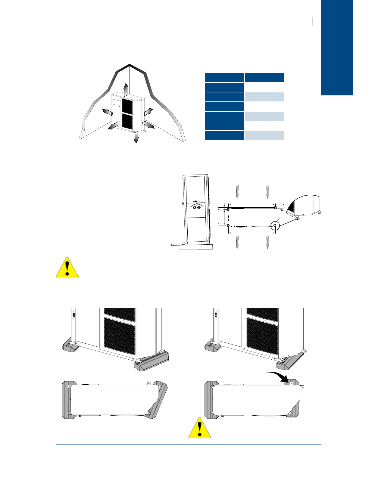
8. HANDLING
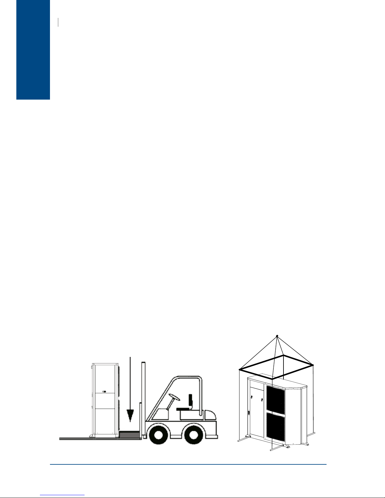
Take care to avoid any rough handling or impacts when unloading and moving the appliance. Only push or
pull the appliance by its base. Place a safety wedge between the unit base and the fork lift truck to avoid
damaging the unit’s structure and casing.
The handles present on the appliance's panels are intended for the removal/retting of the latter and must
not be used for handling the complete appliance (too heavy to be supported by the panels).
Transit holes
Ø30mm
Wedge required along the
entire length of the unit.
² Set of stop cocks with pressure tap
² Set of 2 exible pipes (length 1m)
² Hydraulic connection kit
² Sludge pot (decanting lter)
² Domestic hot water tank (300l)
² Domestic hot water plate exchanger kits for:
Wall-mounted electric tank (DHW outow via the bottom)
Floor-mounted electric tank (DHW outow via the top)
² Directional valve to be linked to the:
Domestic Hot Water function.
Boiler substitution function
Swimming pool function (with temperature probe kit)
² 140 litre buffer tank
² Anti-vibration pads (Anti-vibration mountings)
² 6kW in-line electric heater
² Dual zone Under-oor / Radiator heating kit (modulating valve + electric control box + temperature
probe)
² Dual zone management kit for existing valve (electric control box + temperature probe)
² Wired programmable ambience terminal
² Wireless programmable ambience terminal
}
Accessory recommended for an
optimal functioning
Page 9
English
7
Aqu@Scop HT V2
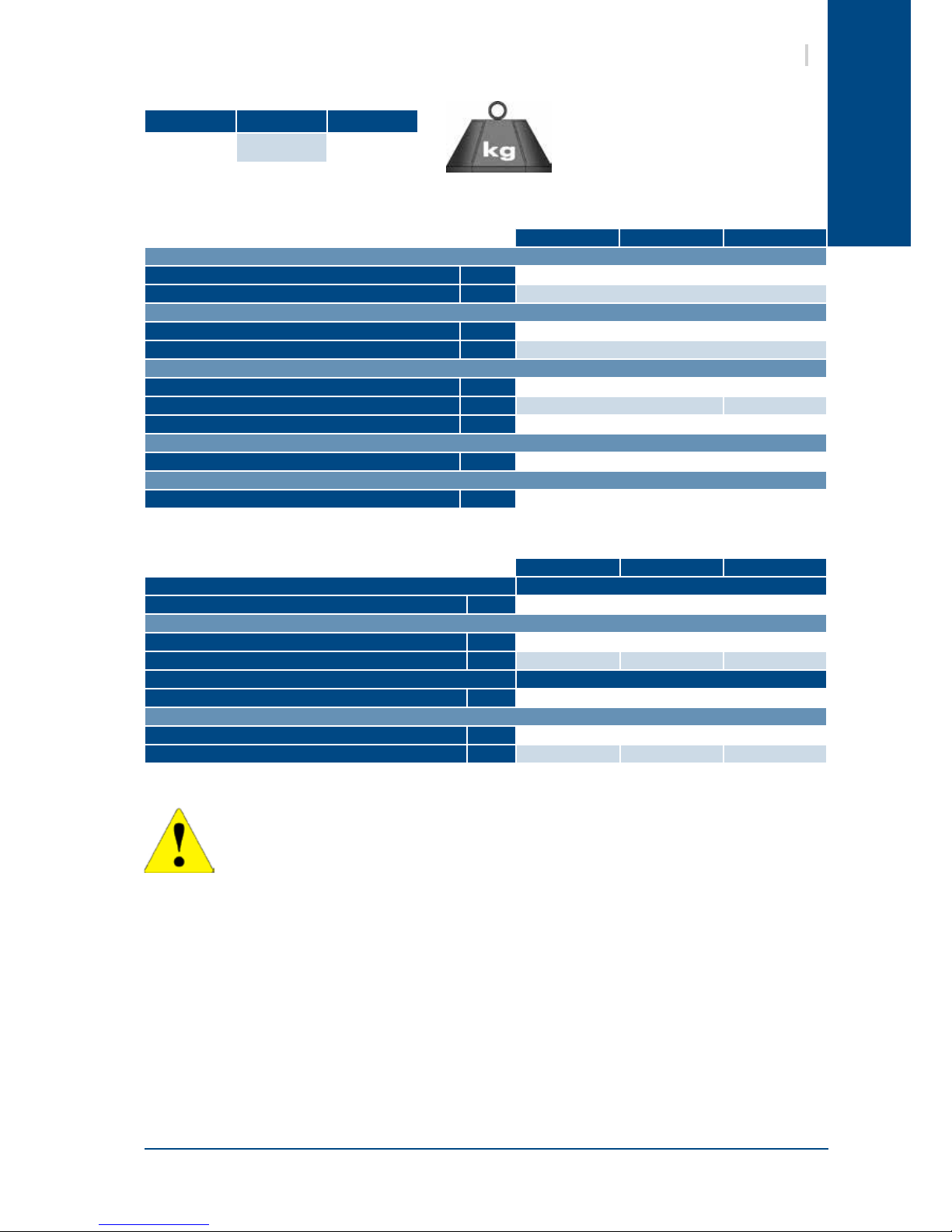
8.1. NET WEIGHT
9. TECHNICAL SPECIFICATIONS
9.1. PHYSICAL CHARACTERISTICS
This equipment contains uorinated gas with greenhouse gas effects covered by the Kyoto agreement.
12-6 14-7 18-9
REFRIGERANT
Type
R407C
Factory charge g
SEE NAME PLATE
HYDRAULIC LINKS
Inlet water gas
1" Female / Rotating nut
Outlet water gas
1" Female / Rotating nut
WATER FLOW
Nominal l/h
1030 / 1230 1480
Minimum l/h
880 / 1050 1260
Maximum l/h
1170 / 1390 1670
FANS
Fans (x2)
206W - 700tr/mn - 6000m3/h
ACOUSTIC PRESSURE
Acoustic pressure – outdoor unit dB(A)
65 65 65
12-6 14-7 18-9
184 209 213
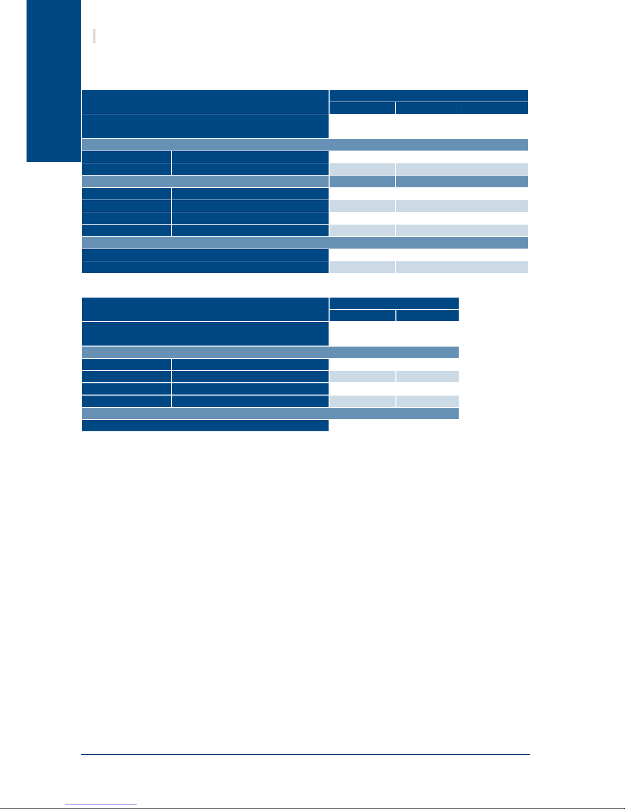
9.2. ELECTRICAL CHARACTERISTICS
12-6 14-7 18-9
SUPPLY VOLTAGE 400V / 3 Ph / 50Hz
Start-up current draw with limiter A
< 60
Maximum current
Only Aqu@ Scop HT A
12.2 13.2 15.2
Aqu@ Scop HT + accessories A
15.5 16.5 18.5
SUPPLY VOLTAGE 230V / 1 Ph / 50Hz
Start-up current draw with limiter A
< 45
Maximum current
Only Aqu@ Scop HT A
25.7 27.2 /
Aqu@ Scop HT + accessories A
29 30.5 /
9.3. OPTIONS COMPATIBILITY
² Domestic hot water plate exchanger kits (SE4287)
² Dual zone kit (SE4288)
² Boilier relief (SE4289 or SE4290)
² Electric heater kit (SE4291 or SE4292)
² Domestic hot water tank (SE4290 or SE4291 or SE4293)
² Dual zone kit + boilier relief (SE4289)
² Dual zone kit + electric heater kit (SE4292)
² Dual zone kit + Domestic hot water tank (SE4293)
² Domestic hot water tank + boilier relief (SE4290)
² Domestic hot water tank + electric heater kit (SE4291)
The card µPC allows to install one or two options at most. The various possible congurations
are the following ones:
Page 10

English
SINGLE /TWO STAGE OPERATING LIMITATIONS
10
15
20
25
30
35
40
45
50
55
60
65
70
-15 -10 -5 0 5 10 15 20-20-25 25
Outdoor temperature (°C)
Leaving water temperature setpoint (°C)
Two stage – min. entering water T.
Two stage – max. leaving water T.
Single stage – max. leaving water T.
TWO
STAGE
SINGLE
STAGE
8
Aqu@Scop HT V2
Aqu@ Scop HT appliances are equipped with a 2-stage output system with a ratio of 1:2.
When heating needs are low and when the required outlet water temperature is below 55° C, only the
rst stage is used at reduced capacity until the temperature balance point is reached. In other cases, the
Aqu@ Scop HT operates at full capacity to supply heating needs until the chosen balance point is reached.
The outlet water temperature is automatically adjusted to the water rule (heating curve) up to a maximum
temperature of 65° C.
9.4. OPERATING LIMITS
Page 11
English
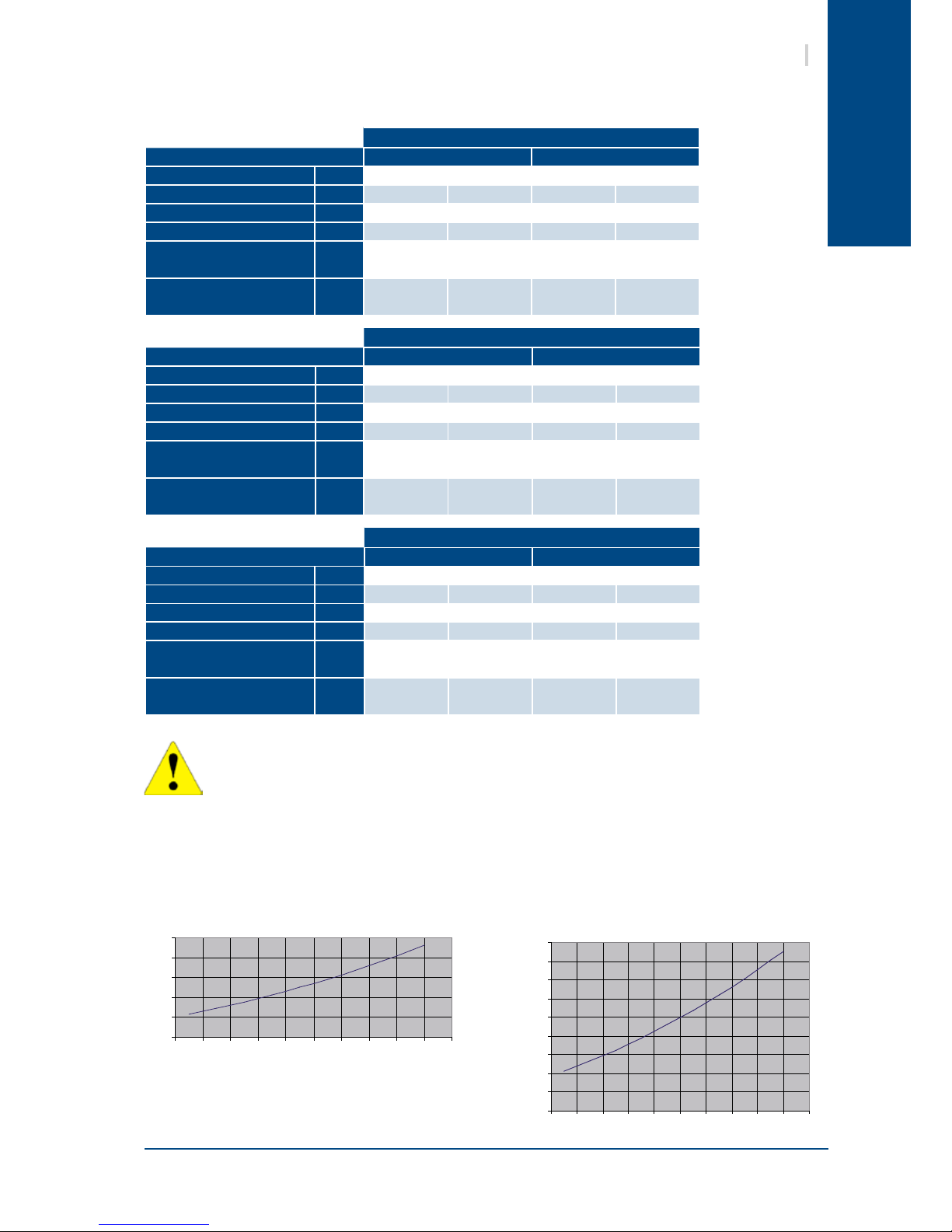
0
0.5
1
1.5
2
2.5
800 900 1000 1100 12 00 1300 1400 1500 1600 1700 1800
kPa
Pressure loss
Water flow (l/h)
P
ressure loss
Water flow (l/h)
kPa
0
0.05
0.10
0.15
0.20
0.25
0.30
0.35
0.40
0.45
800 900 1000 1100 1200 1300 1400 1500 1600 1700 1800
9
Aqu@Scop HT V2
9.5. THERMODYNAMIC DOMESTIC HOT WATER PRODUCTION
Tank capacity: 300l
9.5.1. PERFORMANCE
9.5.2. PRESSURE LOSS
DHW TANK
300l
3-WAY-VALVE
HEATING/DHW
The tank is equipped with a 2.5kW back-up heating element for single or three phase connection. The
performances obtained and stated in the above table are without back-up heating. For higher domestic
hot water temperatures or for Legionnaires disease protection treatment, the use of the back-up electric
heating resistances is required.
The above performance gures are stated for a system with the Domestic Hot Water tank
accessory.
12-6
Conguration C2 Compressor C1+C2 Compressor
Outdoor temp. °C
40 7 0 -10
PAC max. outlet temp. °C
60 60 65 65
Average capacity kW
9 5.5 10.6 9.3
DHW temperature °C
56 58 58 58
Time [min]
Initial temperature: 15°C
min
97 163 85 98
Time [min]
Initial temperature: 35°C
min
49 87 45 53
14-7
Conguration C2 Compressor C1+C2 Compressor
Outdoor temp. °C
40 7 0 -10
PAC max. outlet temp. °C
60 60 65 65
Average capacity kW
11 7.1 13.6 12
DHW temperature °C
54 57 56 57
Time [min]
Initial temperature: 15°C
min
72 124 63 73
Time [min]
Initial temperature: 35°C
min
35 65 32 38
18-9
Conguration C2 Compressor C1+C2 Compressor
Outdoor temp. °C
40 7 0 -10
PAC max. outlet temp. °C
60 60 65 65
Average capacity kW
13.3 8.3 16 14.1
DHW temperature °C
53 56 55 56
Time [min]
Initial temperature: 15°C
min
60 103 52 61
Time [min]
Initial temperature: 35°C
min
28 53 26 31
Page 12

English
10
Aqu@Scop HT V2
10. REFRIGERATION AND HYDRAULIC DIAGRAM
SEE APPENDIX
11. INSTALLATION
The unit is not designed to withstand weights or stresses from adjacent equipment, pipe work
or constructions. Any foreign weight or stress on the unit structure could lead to a malfunction
or a collapse with dangerous consequences for personnel and property. In such an event, the
warranty shall be null and void.
Unit operation depends on air temperature. Any recycling of air extracted by the fan lowers the
air intake temperature across the exchanger ns and alters the standard operating conditions.
The outdoor unit must be installed outdoors with sufcient surrounding clearance to enable unobstructed
air circulation through the appliance and access for maintenance work.
In the case of the unit being sited in areas exposed to high winds, you must avoid the wind hitting the
fan blowing surface areas directly to avoid any risk of recycling cooled air. Exchanger fan operation can be
disrupted by strong winds, which can cause de-icing problems and fan malfunctions.
The arrows show the direction of air circulation through the appliance. (Refer to the § ATTACHEMENT TO THE
GROUND, page 11).
Depending on temperature and outdoor air humidity conditions, water vapour contained in the air can
condense on the nned heat exchanger and even form ice under low outdoor temperature conditions (around
< 5°C). This condensate water and defrosted water runs off via outlets provided under the exchanger. To
aid water run-off and avoid frozen water remaining in the appliance in winter, we recommend that it is
mounted at a height of around 10cm off the ground by installing the ant-vibration mounting kit. In this way,
condensate and defrosted water can run off freely and be absorbed into the ground or channelled to a basin
built under the appliance in order to protect the environment.
In areas where outdoor temperatures fall below 1°C, the system can be equipped with a condensate antifreeze protection system (e.g. a heated pipe sheath, Not supplied).
In order to contain noise levels, we equip our appliances with quiet fans and encase the technical compartment
in sound-proofed panels. However, noise levels can be reduced even further by following a few installation
precautions:
² Do not install the appliance near a bedroom window. Avoid locating the appliance in a corner
(increased reverberated noise).
² Install the rubber pads supplied or anti-vibration pads (available as an option) under the appliance.
² Do not join the concrete slab supporting the appliance to the structure of the dwelling (structure-
borne noise transmission).
11.1. SITING THE INSTALLATION
11.1.1. PREVAILING WIND
11.1.2. CONDENSATE WATER MANAGEMENT
11.1.3. HOW TO REDUCE NOISE POLLUTION
Page 13
English
517
1711244
57414
1244.5
A
B
D
E
C
F
1%
11
Aqu@Scop HT V2
11.2. CLEARANCE
When choosing the location for the appliance, take care to leave sufcient free clearance on all sides to
ensure easy access for maintenance work. The minimum free clearance dimensions indicated must be
observed to ensure both proper system operation and allow access for maintenance and cleaning.
11.3. ATTACHEMENT TO THE GROUND
Unit mounting measurements are shown
on the drawing opposite. A slope of
1 cm/m should be created to assist
rainwater drainage.
Vibration dampers must be tted during
installation to overcome any risks of
vibration being transmitted due to direct
contact with a rigid support surface.
AIR FLOW
THE UNIT MUST NEVER BE
INSTALLED ON A WALL BRACKET.
The appliance must be sited on a level and solid oor and preferably on a masonry surface.
11.3.1. MOUNTING WITH ANTI-VIBRATION SUPPORTS
ANGLED FEET PARALLEL FEET
The rear mounting foot has not
been designed to support the
weight of the unit on its own.
THE REAR FOOT MUST BE USED IN
ACCORDANCE WITH THE ASSEMBLY
ILLUSTRATED BELOW.
REF. DIMENSION
A
800mm
B
500mm
C
500mm
D
400mm
E
800mm
F
100mm
Page 14

English
12
Aqu@Scop HT V2
12. HYDRAULIC LINKS
When choosing and installing water pipes, you must consult and observe all current local standards,
regulations and instructions.
12.1. GENERAL RECOMMENDATIONS
You must design the pipe network with the minimum number of bends and keep the number of changes in
height to the strict minimum. This will reduce installation costs and ensure optimum system performance.
The pipe network must include:
² A vibration elimination system (e.g.: link hoses available as an accessory) on all pipes connected to
the appliance in order to reduce vibrations and noise transmitted to the building fabric.
² Stop cocks to isolate the hydraulic circuit during maintenance.
² Manual or automatic bleed valves at the highest point on the water circuit.
² A suitable system for maintaining water pressure in the circuit (expansion tank).
² The installation of thermometers and pressure gauges on the heat exchanger inlet and outlet to
facilitate day-to-day controls and system maintenance.
12.1.1. ANTI-CLOGGING PROTECTION
When installing Aqu@ Scop HT appliances in existing water circuits,
a sludge trap and a removable mesh lter should be installed
upstream of the appliance.
To avoid any risk of foreign bodies entering the appliance and
to guarantee operating performance, WE STRONGLY RECOMMEND
THAT YOU INSTALL THE WATER FILTER ACCESSORY on the
Aqu@ Scop HT inlet pipe.
To ensure that the system operates correctly you must use suitably sized and properly routed pipes for the
hydraulic links between the Heat pump and the mains network.
The volume of water contained in the installation must be sufcient to avoid any possibility of the compressor
"short cycling", and to guarantee adequate compressor running times in order to provide optimum service
life and to ensure that de-icing cycles are performed properly.To ensure the Aqu@ Scop HT functions
efciently, available installation water volume must be:
12.1.2. MINIMUM HEATED WATER VOLUME REQUIREMENTS – BUFFER TANK.
200l < available water volume < 250l
When water circulation through heat emitters can be interrupted (thermostatic radiator valves closed) or the
heating supply halted, you must ensure that:
² The heat pump maintains its nominal water ow,
² The heat pump operates in a loop with a minimum available volume of 200 litres.
The use of a 3-speed circulation pump enables water ow through the appliance to be adapted to pressure
losses in the system. (Pump supplied set on Max position).
Page 15
English
1
3
2
1 1
1
1
1
1
3
1
5
6
7
8
1
1
12
15
1
14
13
13
Aqu@Scop HT V2
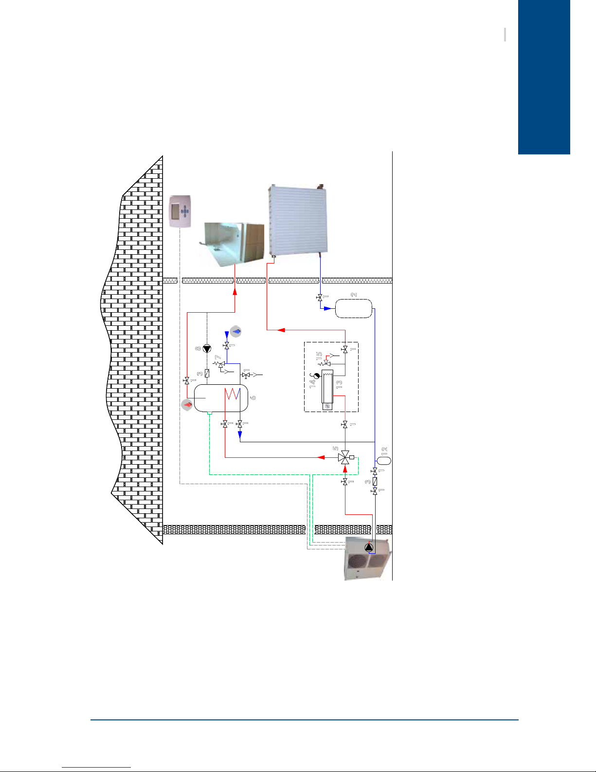
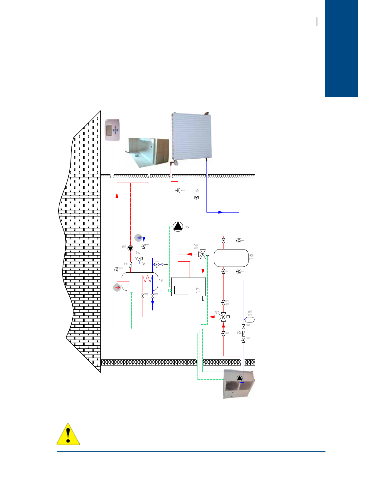
Layout 1: Application without room by room regulation
This layout is recommended when the Aqu@ Scop HT water ow is continuous and close to the nominal
value (no thermostatic valves).
The buffer tank (2) provides extra circulating water volume to maintain the minimum volume.
12.2. STANDARD CIRCUITS
12.2.1. AQU@ SCOP HT ONLY
1. Stop cocks
2. Buffer tank (optional)
3. Filter or sludge trap
4. Relief valve
5. 3-way valve – Domestic Hot Water
6. Domestic Hot Water tank
7. Safety devices
8. Recycling circulation pump
(optional)
12. Expansion tank
13. In-line heater
14. Bleed
15. Safety valve
Page 16
English
1
3
2
4
1 1
1
1
1
1
3
1
5
6
7
8
9
1
1
11
12
15
1
14
13
14
Aqu@Scop HT V2
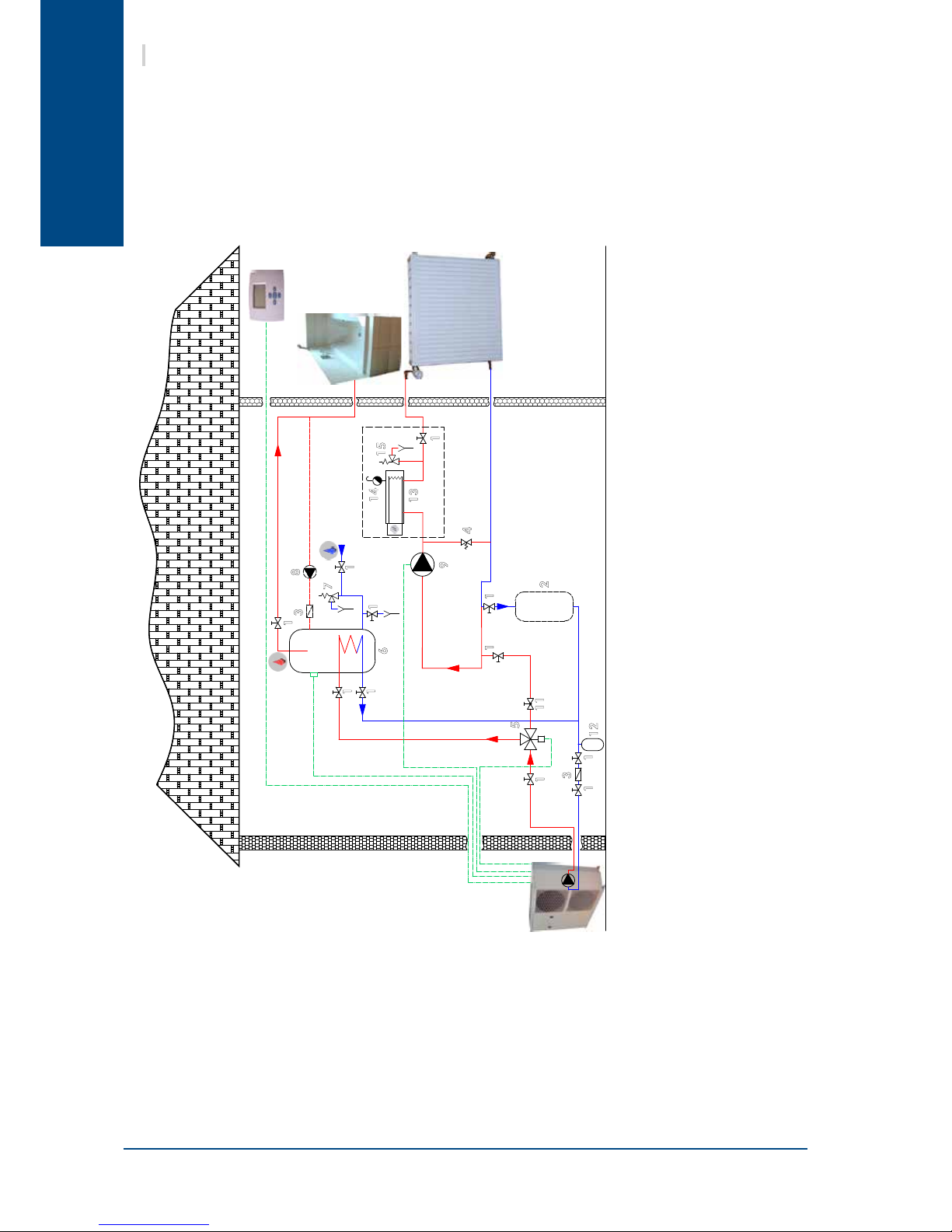
Layout 2: Application with room by room regulation
This layout is recommended for heating installations with wide operating water ow variations (radiator
thermostatic valves present in the system). We strongly recommend including the buffer tank (2) as it
guarantees that the heating loop capacity is higher than the minimum volume when the maximum number
of thermostatic valves are closed.
The ow regulating valve (11) is used to balance the ow in heating mode and domestic hot water production
mode to always ensure optimum Aqu@ Scop HT operation.
1. Stop cocks
2. Buffer tank (optional)
3. Filter or sludge trap
4. Relief valve
5. 3-way valve – Domestic Hot Water
6. Domestic Hot Water tank
7. Safety devices
8. Recycling circulation pump
(optional)
9. Circulation pump
11. Flow regulating valve
12. Expansion tank
13. In-line heater
14. Bleed
15. Safety valve
Page 17
English
1
3
10
4
1 1
1
1
1
3
1
5
6
7
8
9
1
1
1
1
1
11
12
15
1
14
13
15
Aqu@Scop HT V2
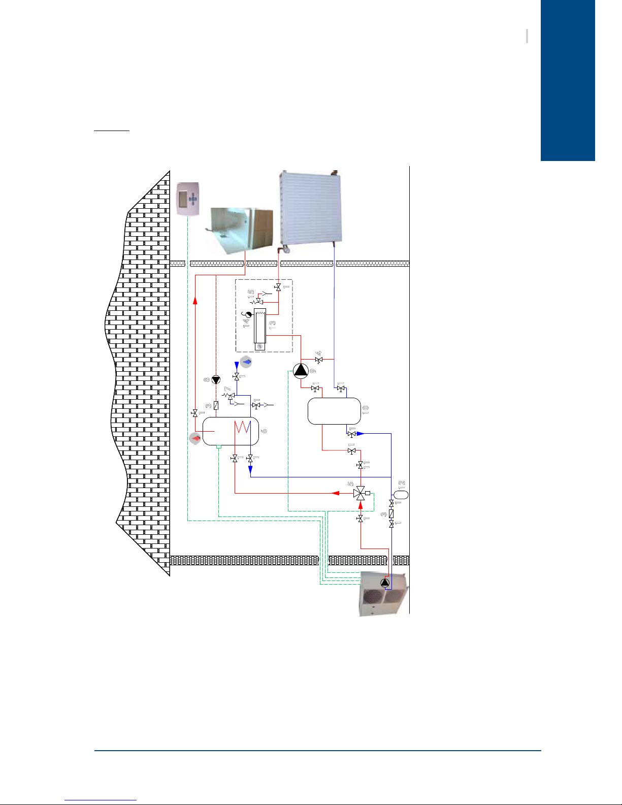
Layout 3: Application with room by room regulation
This layout is also recommended for heating installations with wide operating water ow variations (radiator
thermostatic valves present in the system). Minimum system volume is guaranteed by a mixing tank (10).
Take care when calculating the volume of water in the installation and only take account of 50% of the
mixing tank's volume.
Example: For a useful volume of 100 litres the actual mixing tank volume will be 200 litres.
The ow regulating valve (11) is used to balance the ow in heating mode and domestic hot water production
mode to always ensure optimum Aqu@ Scop HT operation.
1. Stop cocks
3. Filter or sludge trap
4. Relief valve
5. 3-way valve – Domestic Hot Water
6. Domestic Hot Water tank
7. Safety devices
8. Recycling circulation pump
(optional)
9. Circulation pump
10. Mixing tank
11. Flow regulating valve
12. Expansion tank
13. In-line heater
14. Bleed
15. Safety valve
Page 18

English
1
3
10
4
1 1
1
3
1
5
6
7
8
9
1
1
1
1
1
11
12
15
1
14
13
1
1
11
18
16
Aqu@Scop HT V2
1. Stop cocks
3. Filter or sludge trap
4. Relief valve
5. 3-way valve – Domestic Hot Water
6. Domestic Hot Water tank
7. Safety devices
8. Recycling circulation pump
(optional)
9. Circulation pump
10. Mixing tank
11. Flow regulating valve
12. Expansion tank
13. In-line heater
14. Bleed
15. Safety valve
18. Non-return valve
Layout 4: Domestic Hot Water (DHW) production by way of the plate exchanger kit for tment on the
existing DHW tank
Example for a wall-mounted tank (DHW outow via the bottom)
A different kit is required for a oor-mounted tank (DHW outow via the top). Please refer to the corresponding
documentation.
Page 19
English
1
3
4
1 1
1
1
1
3
1
6
7
8
9
1
11
12
1
16
17
5
10
1
1
1
1
17
Aqu@Scop HT V2
12.2.2. AQU@ SCOP HT AS A BOILER SUBSTITUTE
We recommend the tting of a zone valve to avoid heat losses via the boiler when the Aqu@ Scop HT is
working on its own.
All system devices should be of a suitable size to limit pressure losses.
Water ow within the heating circuit is normally driven by the circulation pump already present in the
installation (recommended solution) or by the Aqu@ Scop HT's circulation pump. In this case, you must
ensure that the circulation pump generates sufcient water pressure.
There is no need to replace the existing buffer tank on the circuit to take account of the small volume of
water added by the presence of the Aqu@ Scop HT.
IMPORTANT: the hydraulic kit available as an option enables you to prepare the circuit for connection to the
Aqu@ Scop HT in accordance with our recommendations. The hydraulic kit is available with or without zone
valves.
DO NOT FIT A BOILER SUBSTITUTE VALVE
1. Stop cocks
3. Filter or sludge trap
4. Relief valve
5. 3-way valve – Domestic Hot Water
6. Domestic Hot Water tank
7. Safety devices
8. Recycling circulation pump
(optional)
9. Circulation pump
10. Mixing tank
11. Flow regulating valve
12. Expansion tank
16. 3-way boiler substitute valve
17. Boiler
² WALL-MOUNTED GAS-FIRED BOILER with domestic hot water production and a single
circulation pump used for both heating and domestic hot water.
² BOILER with a circulation pump.
Page 20
English
1
3
1 1
1
1
1
3
1
6
7
8
1
11
12
16
17
5
10
1
1
1
1
9a
9b
19
20
21
21
18
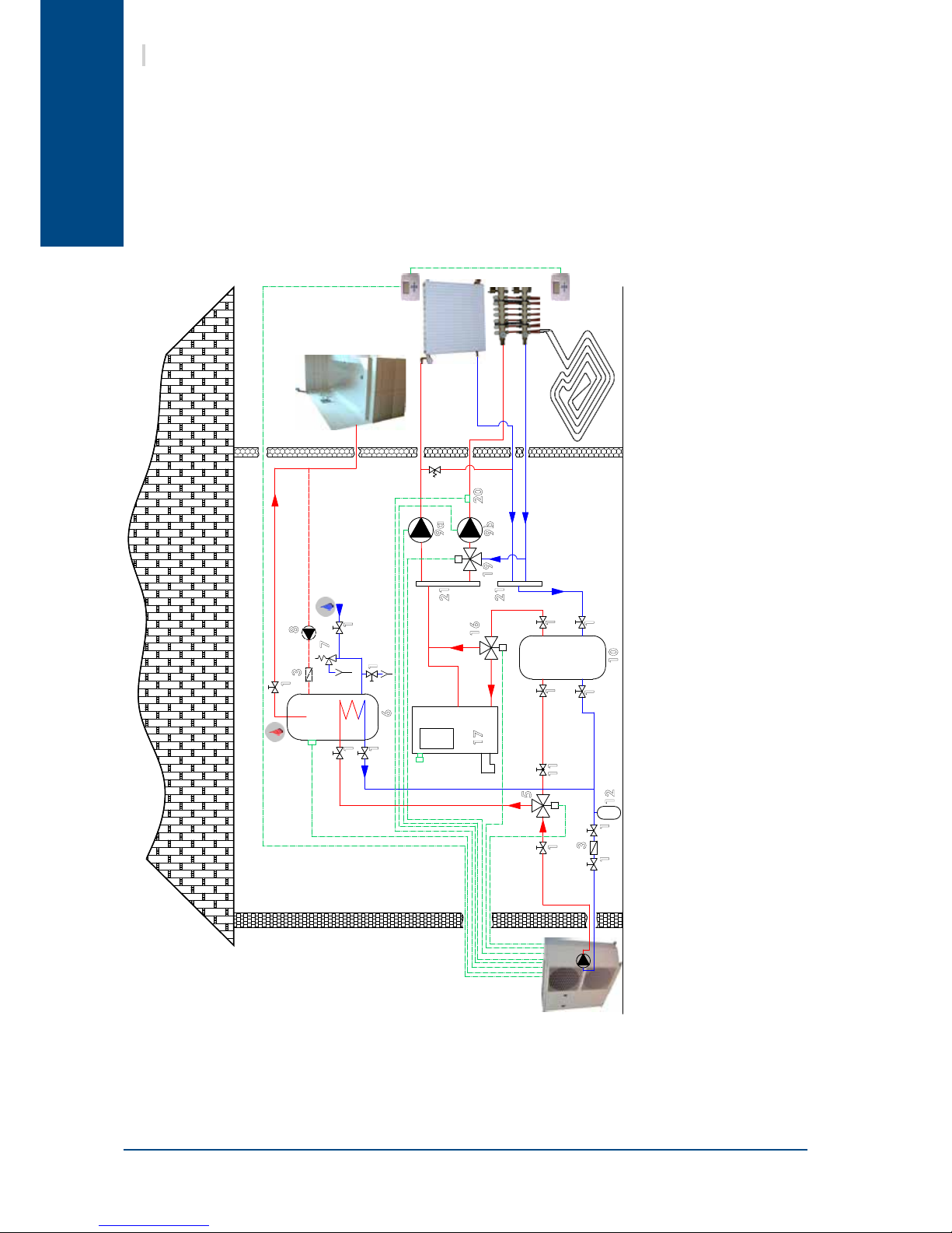
Aqu@Scop HT V2
1. Stop cocks
3. Filter or sludge trap
4. Relief valve
5. 3-way valve – Domestic Hot Water
6. Domestic Hot Water tank
7. Safety devices
8. Recycling circulation pump (optional)
9. Circulation pump (a: radiator / b:
under-oor heating)
10. Mixing tank
11. Flow regulating valve
12. Expansion tank
16. 3-way boiler substitute valve
17. Boiler
19. Low temperature zone
(under-oor heating) 3-way
modulating valve)
20. Under-oor heating outlet
temperature probe (DZWT)
21. Collector
12.2.3. AQU@ SCOP HT – DUAL ZONE INSTALLATION (UNDER-FLOOR HEATING + RADIATORS)
The Aqu@ Scop HT manages a radiator zone (high temperature, zone 2) and an under-oor heating zone
(low temperature, zone 1) by way of an under-oor temperature outlet probe, a modulating 3-way valve
(230V 3 phase motor) and a water circulation pump for each zone.
Each zone can be controlled by a dedicated ambience terminal, which then enables the Aqu@ Scop HT to
manage 2 independent water laws. When the radiators zone is not in operation, the Aqu@ Scop HT switches
over automatically to the under-oor heating water law, and thereby optimises the seasonal COP for the
entire installation.
Page 21

English
19
Aqu@Scop HT V2
The Aqu@ Scop HTmust not run on a network with open loops, likely to cause incidents related to
oxygenation, or with non treated table water.
If the water circuit is to be drained for a time exceeding one month, the circuit must be fully
charged with nitrogen to prevent any risk of corrosion by differential venting.
The manufacturer is not liable for recommendations in terms of water treatment (call a specialized
company).
However, this matter has a critical nature, and particular care must be given to ensure that the type
of treatment applied is effective.
The liability of the manufacturer or its representative will not be sought when non treated water
or non compliant quality water is used.
12.3. WATER QUALITY
The water must be analyzed; the hydraulic network system installed must include all elements necessary
for water treatment: lters, additives, intermediate exchangers, drain valves, vents, check valves, etc.,
according to the results of the analysis.
Using improperly treated or non treated water in the Aqu@ Scop HT may cause scaling, erosion, corrosion
or algae or sludge deposits in the exchangers. Refer to a specialist skilled in water treatment to determine
any treatment to apply. The manufacturer will not be held liable for damages caused when non treated or
improperly treated water, demineralized water, salty water or sea water are used.
Apply the following guidelines :
² No NH4+ ammonium ions in the water, highly detrimental to copper. <10mg/l
² Cl- chloride ions are detrimental to copper with a risk of puncture by picking corrosion. <10mg/l.
² SO42- sulphate ions may cause perforating corrosion. < 30mg/l.
² No uoride ions (<0.1 mg/l)
² No Fe2+ and Fe3+ ions, particularly in case of dissolved oxygen. Fe< 5mg/l with dissolved oxygen
< 5mg/l. The presence of these ions with dissolved oxygen indicates corrosion of steel parts, likely
to generate corrosion of copper parts under Fe deposits, particularly in the case of multitubular
exchangers.
² Dissolved silica: silica is an acid element of water and may also cause corrosion. Content < 1mg/l.
² Water hardness: TH > 2.8K. Values between 10 and 25 may be recommended. This facilitates scaling
deposits likely to limit copper corrosion. Excess TH values may lead to clogging the pipes.
² TAC<100
² Dissolved oxygen: Prevent any sudden change in the water's oxygenation conditions. Also, avoid
deoxygenating water by sparging inert gas as well as overoxygenating it by pure oxygen sparging.
Disturbing oxygenation conditions destabilizes copper hydroxides and particle salting-out.
² Electrical Resistivity - Conductivity: The higher the resistivity, the slower the corrosion. Values above
3000 ohm/cm are preferred. A neutral environment favours maximum resistivity. For electrical
conductivity, values around 200-600 S/cm can be recommended.
² pH: neutral pH at 20°C (7 < pH < 8)
Page 22
English
20
Aqu@Scop HT V2
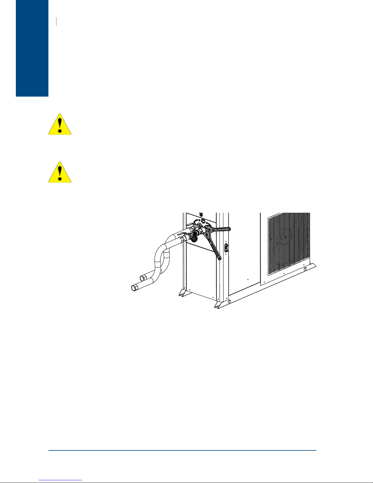
You must check water tightness and the cleanliness of the installation before connecting the Aqu@ Scop HT .
For the Aqu@ Scop HT 's WATER INLET and OUTLET connections, you must install manual stop cocks with
the same diameter as the main pipe work. This will enable maintenance work to be carried out on the
Aqu@ Scop HT without having to bleed the entire system.
A link valve with pressure tap kit is available.
The Aqu@ Scop HT must be protected by a water lter. When connecting this device to the Aqu@ Scop HT ,
take care to keep the water lter sieve pointing downwards. A sludge trap should be tted in the event of
high sludge build-ups.
WARNING!
Take care not to damage the hydraulic pipe links by applying too much tightening pressure. Use a second
wrench to compensate for the tightening torque.
You should always use a counter-wrench for
tightening valves.
To guarantee proper energy efciency and compliance with current standards, water pipes passing through
uninhabited zones should be properly lagged to retain heat.
To achieve correct insulation with conductivity of 0.04 W/mK, lag the pipes with insulating material with a
radial thickness between 25mm and 30 mm.
THE MANUFACTURER'S WARRANTY IS VOID IF THE FILTER SUPPLIED WITH THE AQU@ SCOP HT IS
NOT INSTALLED TO PROTECT THE APPLIANCE
AN EXPANSION TANK ADAPTED TO THE VOLUME OF WATER IN THE INSTALLATION MUST BE
INSTALLED.
It is important to ensure that the mains water supply pressure is sufficient to fill the installation.
12.4. CONNECTION TO THE CENTRAL HEATING LOOP
12.5. HEAT INSULATION
Page 23
English
21
Aqu@Scop HT V2
12.6. FILLING THE SYSTEM WITH WATER
Once the installation is complete and after having clean and rinsed out the circuit network, you must ll
the water circuit in accordance with current professional standards until you obtain the service pressure
which will be:
0.5 bar < P. service < 2.5 bars.
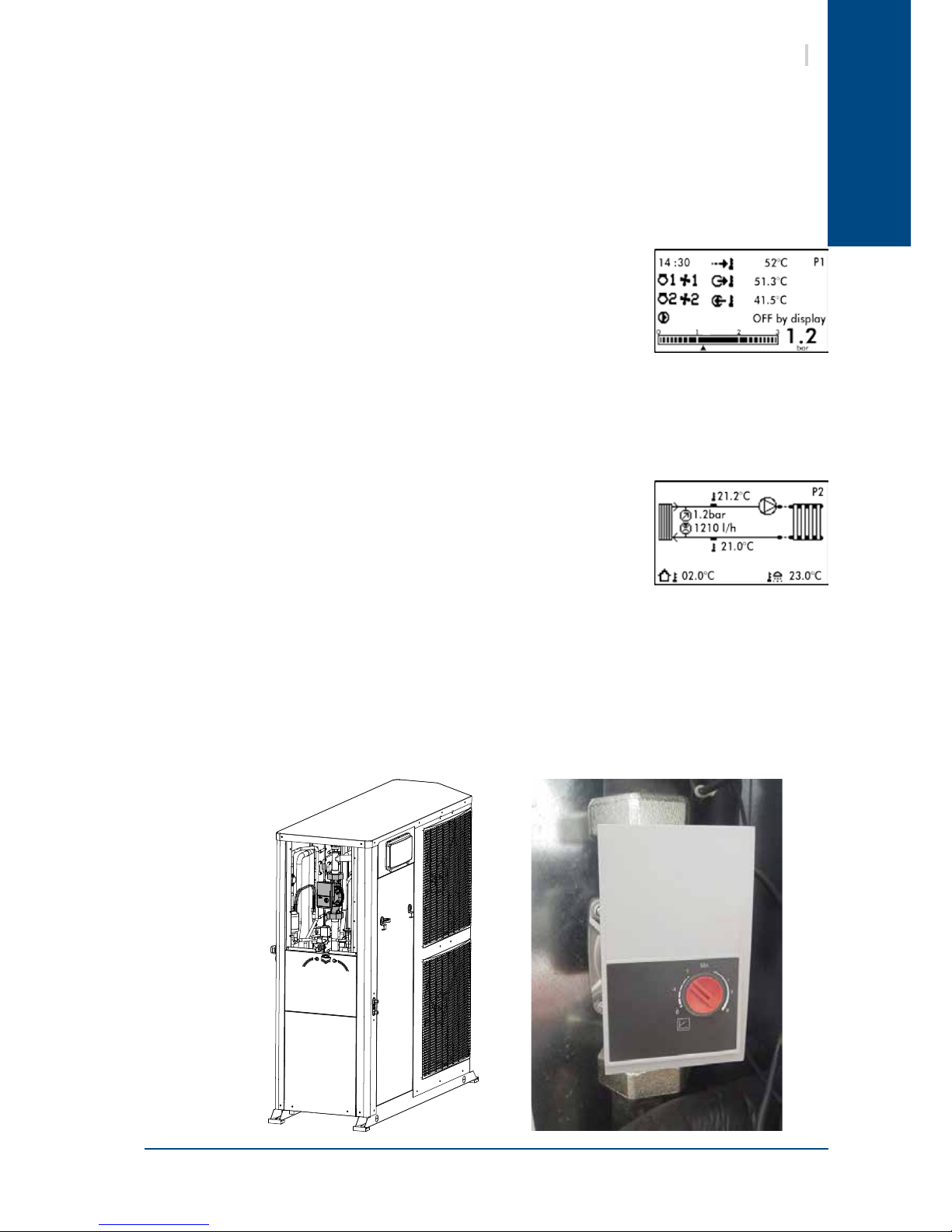
The Aqu@ Scop HT is equipped with an electronic water pressure sensor. This can be viewed on the main P1
screen on the display, as well as on the Maintenance screens.
The water supply should come either from the mains network or from the
Heat Pump or from any other point on the installation.
Check that the automatic bleed valve operates correctly.
You must completely bleed the circuit of all air to ensure efcient operation.
Close the inlet water valve once the hydraulic circuit is lled correctly.
The condenser water circuit is equipped with a vortex effect electronic ow
meter. This device provides real-time readings of the installation's water ow
and reassurance that this ow is adequate before starting the unit.
The appliance is also equipped with a group of safety devices including a
valve set at 3 bars, and a manual relief valve.
Water ow can be viewed on screen P2 as well as on the Maintenance screens.
Use the water circulation pump speed selector to adjust the ow in the installation at the recommended
nominal value (Refer to the § PHYSICAL CHARACTERISTICS, page 7). Pressure drop of the installation
must be situated in the circulator operating range.
12.7. ELECTRONIC FLOW METER
12.8. WATER FLOW REGULATION
Page 24

English
22
Aqu@Scop HT V2
13. WIRING DIAGRAM AND LEGEND
N 802
13.1. WIRING DIAGRAM
SEE APPENDIX
13.2. LEGEND
13.2.1. POWER SUPPLY
13.2.2. WIRING DIAGRAM KEY DESCRIPTIONS
FT1/2 : M1/2 compressors thermo-magnetic relay (three phase models)
FF1/2 : M1/2 compressors protection fuse carrier (single phase models)
KM1/2 : M1/2 compressors power contactor or relay
M1/2 : Compressors
CM1/2 : M1/2 compressors capacitors (single phase models)
AS1/2 : "Soft START" starter
R1/2 : Sump resistance
OF1/2 : Air exchanger fan motor
KOF1 : OF1 fan motor relay
FOF1/2 : OF1/2 motors internal safety
COF1/2 : OF1/2 motors capacitors
CF : OF1/2 fan motor variator
RAG : anti-freeze resistance
TAG : anti-freeze thermostat
FFC : Control circuit protection fuse carrier
Terminal connections:
230V +/-10% 50Hz
² L : phase
² N : neutral
² : ground
3N~400V +/-10% 50Hz
² L1 (L1) : phase
² L2 (L2) : phase
² L3 (L3) : phase
² N (N) : neutral
² : ground
This supply comes from a CIRCUIT BREAKER or a FUSE HOLDER equipped with aM type fuses supplied by the
installer. Fuse sizes are indicated on the chart on the following page.
The appliance's electrical installation and wiring must comply with the country's current standards.
SE 4213 Aqu@ Scop HT 12-6 Power 1-Phase 230V +/-10% 50Hz
SE 4214 Aqu@ Scop HT 12-6 Control 1-Phase 230V +/-10% 50Hz
SE 4215 Aqu@ Scop HT 14-7 Power 1-Phase 230V +/-10% 50Hz
SE 4216 Aqu@ Scop HT 14-7 Control 1-Phase 230V +/-10% 50Hz
SE 4217 Aqu@ Scop HT 12-6/14-7 Power 3-Phases 3N~400V +/-10% 50Hz
SE 4218 Aqu@ Scop HT 12-6/14-7 Control 3-Phases 3N~400V +/-10% 50Hz
SE 4219 Aqu@ Scop HT 18-9 Power 3-Phases 3N~400V +/-10% 50Hz
SE 4220 Aqu@ Scop HT 18-9 Control 3-Phases 3N~400V +/-10% 50Hz
Page 25

English
23
Aqu@Scop HT V2
KA1 : Phase sequence and cut-out control module (three phase models)
µPC : Controller
FT1/2 : Thermo-magnetic relays ancillary contacts for M1/2 compressors
HP : Automatic reset high pressure switch
EEV : Electronic pressure relief valve
IHP : Intermediate high pressure switch
DHP : De-icing high pressure switch
RV : 4-way cycle changeover valves
ISV : Injection valve
DRV : De-icing valve
ESV : Oil equalization valve
EP : Pressure transducer (evaporation pressure)
OCT : De-icing temperature probe (evaporator inlet)
OAT : Outdoor temperature probe
CDT : High discharge temperature
CST : Evaporation temperature probe
FFT : T1 transformer protection fuse (24V secondary circuit)
T1 : Ambience terminal 230/24V power supply transformer
WFL : Flow meter (water flow measurement)
WPR : Water pressure sensor
WP : Water pump
KWP : WP water pump relay
EWT : Inlet water temperature probe
LWT : Outlet water temperature probe
13.2.2.1. OPTIONS
DZ WP/2 : Dual zone water pumps
DZ MV : Dual zone mixer valve
AEH1 : Backup electric heating (Stage 1)
AEH2 : Backup electric heating (Stage 2)
BOILER : Hot water boiler (ON dry switch)
DHW WP : Domestic Hot Water circulation pump (kit with plate exchanger)
DHW V : Domestic Hot Water 3-way valve
DHW EH : Domestic Hot Water tank electric heating resistance
BR V : Substitute Boiler 3-way valve
DZWT : Dual zone water temperature probe (Under-floor heating outlet)
DHWT : Domestic hot water temperature probe
SPWT : Swimming pool water temperature probe
ON/OFF : Remote ON/OFF switch (Summer/Winter parameter settings)
LS : Off-peak hours electricity contact (DHW)
EMH : Backup heating switch (electric heater and boiler substitution)
Page 26
English
24
Aqu@Scop HT V2
13.2.3. CONTACTOR FUSE RATINGS, NOMINAL CURRENTS SETTINGS (CLASS AC3/AC1)
Supply voltages
3N~400V +/-10% 50Hz
12-6 14-7 18-9
Only Aqu@ Scop HT
General protection fuse rating (not supplied) aM type (1)
16A 16A 20A
Fuse ratings
FFC aM type
6A 6A 6A
FFT T type
1.6A 1.6A 1.6A
Thermo-magnetic cut-out switch
FT1 Plage
9 - 14A 9 - 14A 9 - 14A
Réglage
10A 11A 13A
FT2 Plage
4 - 6.3A 4 - 6.3A 4 - 6.3A
Réglage
4.2A 5.1A 5.6A
Contactors
KM1
12A 12A /
KM2
9A 9A 9A
(1) These values are provided for information purposes only and must be checked and adjusted in relation to
currently applicable standards. They vary depending on the type of installation and the choice of conductors.
Supply voltages
230V +/-10% 50Hz
12-6 14-7
Only Aqu@ Scop HT
General protection fuse rating (not supplied) aM type (1)
32A 32A
Fuse ratings
FF1 aM type
25A 25A
FF2 aM type
12A 16A
FFC aM type
6A 6A
FFT T type
1.6A 1.6A
Contactors
KM2
12A /
Page 27

English
25
Aqu@Scop HT V2
14. ELECTRICAL CONNECTIONS
WARNING
Before carrying out any work on the equipment,
make sure that the electrical power supply is
disconnected and that there is no possibility
of the unit being started inadvertently.
Non-compliance with the above instructions
can lead to injury or death by electrocution.
The electrical installation must be performed by a fully qualied electrician, and in accordance with local
electrical standards and the wiring diagram corresponding to the unit model.
Any modication performed without our prior authorisation may result in the unit’s warranty being declared
null and void.
The power supply cable section must be sufcient to provide the appropriate voltage to the unit’s power
supply terminals, both at start-up and under full load operating conditions.
The use of under-sized power supply cables can lead to major losses of around 100W to 200W.
The power supply cable shall be selected in accordance with the following criteria:
1. Power supply cable length.
2. Maximum unit starting current draw – the cables shall supply the appropriate voltage to the unit
terminals for starting.
3. Power supply cables’ installation mode.
4. Cables’ capacity to transport the total system current draw.
Short circuit protection shall be provided. This protection shall comprise fuses or circuit breakers with high
breaking capacity, mounted on the distribution board.
If the planned installation includes an ambience terminal, the latter must be connected with shielded cable
which must not run through the same conduits as the power supply cables, as the possible voltage generated
could cause a unit operating fault.
VERY IMPORTANT:
3N~400V-50HZ
The outdoor unit is equipped as standard with a phase sequence and cut-out controller located in the
electrical box.
THE LED’s INDICATE THE FOLLOWING CONDITIONS:
Green LED = 1
Yellow LED =1
Power ON
The compressor rotation
direction is correct.
Green LED = 1
Yellow LED =0
Phase inversion or phase
absent (L1)
The compressor and the fans
do not start.
Green LED = 0
Yellow LED =0
Phase absent (L2 or L3)
The compressor and the fans
do not start.
14.1. PHASE SEQUENCE AND CUT-OUT CONTROLLER
Page 28

English
26
Aqu@Scop HT V2
14.2. PROGRESSIVE START-UP
The Aqu@ Scop HT 18-9 is equipped with a progressive starter
(soft start) for the C1 compressor. The starter is situated in the
electrical box of the outdoor unit and marked "AS1".
It is important to check the following settings:
² Start slope 1s
² Stop slope 0s
² Minimum starting voltage 60%
Start slope
Stop slope
Minimum
starting
voltage
3N~400V-50HZ
IMPORTANT :
The compressors are equipped with a soft starter. The starter is situated in the electrical box of the outdoor
unit and marked "AS1/2".
230V +/-10% 50Hz
THE LED’s INDICATE THE FOLLOWING CONDITIONS:
Green
diode
Red diode Meaning Recommended action Comments
On Off No fault
Off Off
No supply voltage present
at starter terminals.
Check the power supply to the PAC.
Check the condition of the 230V
protection fuse. Replace the fuse if it
has melted.
Flashing Off
Insufficient supply voltage
(compressor stopped).
Measure the compressor starter
supply voltage at rest. Cut the power
supply to the PAC and check whether
or not the fault reappears. Refer to
the following cause in the event of
repeated failure.
Defective starter power
supply component.
Cut the power supply to the PAC. If the
fault persists, replace the starter.
On
Flashing
twice
Insufficient compressor
starting voltage (<190V).
Check the mains supply voltage at
rest. Contact the electricity supplier if
< 207V.
The alarm resets itself automatically
after 5 min. If the fault re-occurs
during the next start-up procedure,
the compressor seizes and the power
supply has to be disconnected to reset
it.
With the compressor running, check
the mains supply voltage and the
starter output voltage. In the event of
major voltage drop, check the diameter
of the PAC power supply cable. As
a last resort, contact the electricity
supplier.
On
Flashing 3
times
Excessive compressor
starting current.
Force the compressor to start several
times and check whether it is a oneoff or recurring fault.
The alarm resets itself automatically
after 5 min. If the fault re-occurs
during the next start-up procedure,
the compressor seizes and the power
supply has to be disconnected to reset
it.
If the fault persists, when the
compressor is running, check for
normal current draw. In the event of
excessively-high current draw, replace
the compressor.
Starter fault. Replace the starter.
On
Flashing 4
times
Starter internal condenser Replace the starter.
On
Flashing 5
times
Incomplete or defective
compressor starting
sequence
Force the compressor to start several
times and check whether it is a oneoff or recurring fault.
The alarm resets itself automatically
after 5 min. If the fault re-occurs
during the next start-up procedure,
the compressor seizes and the power
supply has to be disconnected to reset
it.
In the event of a persistent fault, check
the compressor power supply cable.
Page 29

English
NN L LNN
L1
L1 L2 L3
27
Aqu@Scop HT V2
14.3. CONNECTIONS
A circuit breaker or fuse holder ( not supplied ) must be installed on the main power supply of the unit in
accordance with the circuit diagram; for the ratings, refer to the electrical specications.
Remove the inspection cover to gain access to the electrical connection box.
Pass the power supply cable through the cable passage provided on the appliance.
Install end ttings suitable for the cable section to ensure a good contact. Make the connections as shown.
14.3.1. MAINS POWER SUPPLY
INSPECTION
COVER
MAINS POWER SUPPLY
ELECTRICAL CABLE
PASSAGE
MAINS POWER
SUPPLY 400V
MAINS POWER SUPPLY
230V
MAINS POWER
SUPPLY
3N~400V-50HZ 230V +/-10% 50Hz
Page 30

English
A
B
24V AC
24V AC
GND
{
{
A
B
24V AC/1
24V AC/2
GND
{
{
28
Aqu@Scop HT V2
14.3.2. AMBIENCE TERMINAL
AMBIENCE TERMINAL
CONNECTION
COMMUNICATION
POWER SUPPLY
2 separate cables for
power supply (24V) and
communication (A-B-GND).
Power supply 24V:
Single pair cable: 1 mm²
Communication:
Shielded twisted single pair
cable with screen 0.33 mm²
to 0.5mm² (AWG 20/22)
COMMUNICATION
POWER SUPPLY
Page 31

English
µPC
µPC
µPC
29
Aqu@Scop HT V2
15. DOMESTIC HOT WATER
Fit the valve in accordance with the ow direction marks etched on the valve.
THE CONNECTIONS MUST CORRESPOND EXACTLY WITH THE FLOW DIRECTIONS INDICATED ON THE LAYOUT
DIAGRAM FOR THE TYPE OF INSTALLATION.
15.1. CONNECTION TO THE CENTRAL HEATING LOOP
An On-Off 3-way valve directs hot water produced by the Aqu@ Scop HT to either the heating circuit or
the domestic hot water tank. Hydraulic connections must be made in accordance with the circuit layout
diagrams provided.
Warning: You must ensure that the 3-way valve orices (marked A, B and AB) are connected correctly to the
circuit in order for the valve to operate in accordance with the electrical diagram provided.
Position the ow changeover
control in the Y1 position.
A
B
AB
Motor disengagement
DOMESTIC HOT
WATER TANK
Aqu@ Scop HT
HEATING
CIRCUIT
DHW VALVE DHW TANK DHW SENSOR
15.1.1. 3-WAY HEATING / DOMESTIC HOT WATER VALVE
15.1.1.1. ELECTRICAL CONNECTIONS
Page 32

English
PROG
Main screens P1 P4
Screen Reference
INSTALLATION MENU
ENTER
Power on screen
ESC
INSTALLATION MENU
MAIN MENU
MP
ON/OFF-SUM/WIN
O0
HEAT CURVE
L1 L4
DOMESTIC HOT WATER
ES0 ES10
ROOM TERMINAL
TH0 TH3
ALARM LOG
H1 H2
OPERATING TIME
TM1 TM2
Screen Reference
Password
NEW PASSWORD
MANUAL OUPUTS
MANUAL DEICING
COMPRESSOR MNGT
MAINTENANCE
INSTALLATION CONFIG
DUAL ZONE
BOILER RELIEF
ELECTRIC HEATER
IE1 IE7
DOMESTIC HOT WATER
WATER SETPOINT
WATER PUMP
MI
ENTER ENTER
ENTER
BOILER RELIEF
R0 R1
30
Aqu@Scop HT V2
The Aqu@ Scop HT controller manages domestic hot water production in accordance with the following
operating modes:
² PERMANENT COMFORT MODE
Domestic hot water production has priority over heating except when the ambiance temperature /
set temperature difference is greater than 2° C (Maximum one hour).
Example: Set temperature = 20°C, Ambience < 18°C
² ECONOMY MODE
Domestic hot water is produced during off-peak hours (dry contact) or in accordance with times
programmed in the controller.
Option: Possibility to restart domestic hot water production outside off-peak hours if the water
temperature has reached a programmable minimum temperature.
² IMMEDIATE DOMESTIC HOT WATER PRODUCTION
The Aqu@ Scop HT 's regulator enables domestic hot water production to be forced as required. At
the end of the cycle, the system returns to its usual operating mode.
15.2. DOMESTIC HOT WATER PRODUCTION MODES
15.3. DOMESTIC HOT WATER HEATING FUNCTION ACTIVATION
The Legionnaires' Disease protection treatment managed by the Aqu@ Scop HT 's controller is fully
programmable (frequency, temperature threshold, treatment length).
The PERMANENT COMFORT and ECONOMY modes place priority on thermodynamic heating. In the event of
excessive demand for Domestic Hot Water Temperature that does not permit the compressor(s) to operate,
the backup electric heating function is activated. In order to achieve energy savings, it is important to use
the lowest possible set temperature points.
We recommend:
Eco set temperature < Comfort set temperature < 53°C
Page 33

English
PROG
Main screens P1 P4
Screen Reference
INSTALLATION MENU
ENTER
Power on screen
ESC
INSTALLATION MENU
MAIN MENU
MP
ON/OFF-SUM/WIN
O0
HEAT CURVE
L1 L4
DOMESTIC HOT WATER
ES0 ES10
ROOM TERMINAL
TH0 TH3
ALARM LOG
H1 H2
OPERATING TIME
TM1 TM2
Screen Reference
Password
NEW PASSWORD
MANUAL OUPUTS
MANUAL DEICING
COMPRESSOR MNGT
MAINTENANCE
INSTALLATION CONFIG
DUAL ZONE
BOILER RELIEF
ELECTRIC HEATER
EH0 EH7
DOMESTIC HOT WATER
WATER SETPOINT
WATER PUMP
MI
ENTER ENTER
ENTER
BOILER RELIEF
R0 R1
31
Aqu@Scop HT V2
16. IN-LINE ELECTRIC HEATER
16.1. ELECTRICAL CONNECTIONS
16.2. OPERATING MODE
SEE APPENDIX
Operating parameters for these modes can be set via the display on the Aqu@ Scop HT .
16.2.1. BOOST MODE
The backup electric heating offers additional capacity when the demand for heating is higher than the
capacity of the Aqu@ Scop HT. The aim is to maintain occupant comfort, while favouring thermodynamic
operation for optimised performance.
The resistances are only activated below a certain outdoor temperature (values can be set for Stage 1, AEH1
and Stage 1+2, AEH1+AEH2) and only if the Aqu@ Scop HT regulation system detects a lack of capacity in
compressor only mode (check on water temperature and ambient temperature).
Activation of the EMH Back-up switch on the heater switches the Aqu@ Scop HT into Back-up mode.
16.2.2. BACK-UP MODE
As opposed to Booster mode, this mode operates only when the user activates the EMH Back-up switch
(this supposes an alarm on the Aqu@ Scop HT ). Outdoor temperature conditions are overridden and priority
is no longer given to the thermodynamic mode but to the heating resistances that are nevertheless still
controlled by the Aqu@ Scop HT .
16.3. ELECTRIC HEATER FUNCTION ACTIVATION
Page 34

English
PROG
Main screens P1 P4
Screen Reference
INSTALLATION MENU
ENTER
Power on screen
ESC
INSTALLATION MENU
MAIN MENU
MP
ON/OFF-SUM/WIN
O0
HEAT CURVE
L1 L4
DOMESTIC HOT WATER
ES0 ES10
ROOM TERMINAL
TH0 TH3
ALARM LOG
H1 H2
OPERATING TIME
TM1 TM2
Screen Reference
Password
NEW PASSWORD
MANUAL OUPUTS
MANUAL DEICING
COMPRESSOR MNGT
MAINTENANCE
INSTALLATION CONFIG
DUAL ZONE
BOILER RELIEF
IR0 IR4
ELECTRIC HEATER
DOMESTIC HOT WATER
WATER SETPOINT
WATER PUMP
MI
ENTER ENTER
ENTER
BOILER RELIEF
R0 R1
32
Aqu@Scop HT V2
17. BOILER RELIEF
17.1. ELECTRICAL CONNECTIONS
The boiler relief function uses the digital outputs of the in-line electric heater function to control the hot
water boiler ON/OFF switch (Boiler dry contact switch) as well as a 3-way valve output (230V BRV). A
switch should be wired to the ICS input to ensure operation in Back-up mode.
We strongly recommend the installation of the ambience terminal for effective operation
of the Boiler Relief function. In the absence of an ambience terminal the Aqu@ Scop HT will
be unable to optimise hot water boiler operation and this will lead to unnecessary energy
consumption.
17.2. OPERATING MODES
Operating parameters for these modes can be set via the display on the Aqu@ Scop HT.
17.2.1. BOOST MODE
Hot water boiler operation is only authorised below a certain set outdoor temperature value and the appliance
can also be placed in forced shutdown mode below a different outdoor temperature value. Just as the
electric heater, the Aqu@ Scop HT continuously checks the water temperature and the ambient temperature
to optimise compressor operation and to only start the hot water boiler when absolutely necessary.
The Aqu@ Scop HT can also be set to manage a heat curve on the hot water boiler higher than the
temperature set for the appliance (65° C maximum).
17.2.2. BACK-UP MODE
Activation of the EMH switch (to be wired by the installer) or the Back-up parameter, via the "Boiler Relief"
tab on the main menu of the Aqu@ Scop HT display, switches the system into Back-up mode and both
outdoor temperature and ambient temperature conditions are overridden.
17.3. BOILER RELIEF FUNCTION ACTIVATION
Page 35

English
PROG
Main screens P1 P4
Screen Reference
INSTALLATION MENU
ENTER
Power on screen
ESC
INSTALLATION MENU
MAIN MENU
MP
ON/OFF-SUM/WIN
O0
HEAT CURVE
L1 L4
DOMESTIC HOT WATER
ES0 ES10
ROOM TERMINAL
TH0 TH3
ALARM LOG
H1 H2
OPERATING TIME
TM1 TM2
Screen Reference
Password
NEW PASSWORD
MANUAL OUPUTS
MANUAL DEICING
COMPRESSOR MNGT
MAINTENANCE
INSTALLATION CONFIG
DUAL ZONE
DZ1 DZ8
BOILER RELIEF
ELECTRIC HEATER
DOMESTIC HOT WATER
WATER SETPOINT
WATER PUMP
MI
ENTER ENTER
ENTER
BOILER RELIEF
R0 R1
You MUST install one room terminal per zone.
33
Aqu@Scop HT V2
18. DUAL ZONE
18.1. ELECTRICAL CONNECTIONS
SEE APPENDIX
18.2. ACTIVATING THE DUAL ZONE FUNCTION
18.3. AMBIENCE TERMINAL
CHANGING THE AMBIENCE TERMINAL ADDRESS FOR ZONE 2.
See the communicating ambiance terminal's installation manual (IOM WATTS 01-N-2ALL).
The double zone function requires the use of one ambiance terminal per zone. You must specify one address
per ambiance terminal.
² Zone 1 : Address 1
² Zone 2 : Address 2
You must specify the type of emitter for each zone. Zone 1 corresponds to the
low temperature zone. Setting the Aqu@Scop HT controls the water output
temperature using the DZMV modulating valve and the DZWT temperature
sensor.
Page 36

English
34
Aqu@Scop HT V2
19. COMMISSIONING
19.1. PRE-START CHECK LIST
1. Electrical installation has been carried out according to unit wiring diagram and the Supply Authority
Regulations.
2. Size fuses or circuit breaker has been installed at the main power supply.
3. Supply voltages as specied on unit wiring diagram.
4. Check the tightness of wire to component connections.
5. the cables and wires are clear of or protected from pipework and sharp edges.
6. Check the electrical grounding of the appliance.
1. Check that the external water circuit components (pumps, user equipment, lters, expansion tank
and reservoir if supplied) have been correctly installed in accordance with the manufacturer’s
recommendations and that the water inlet and outlet connections are correct.
2. Check the presence, direction and position of the water lter upstream of the appliance. Rinse the
lter after the rst 2 hours of operation.
3. Check that the water quality complies with stated standards.
4. Check that the hydraulic circuit is lled correctly and that the uid ows freely without any signs of
leaks or air bubbles.
5. Adjust the water ow in order to comply with the specications. (Refer to the § WATER FLOW
REGULATION, page 21)
6. Check the presence and position of the stop cocks to isolate the appliance for maintenance.
7. Check the presence of the air bleed valve.
8. Check protection against freezing (heat isolation, antifreeze percentage if required...).
9. Check that the bleed valve in the appliance has been opened.
Before commissioning the system, you must carry out a certain number of installation checks to ensure that
the appliance will operate in the best possible conditions. The following list of checks is not exhaustive and
only serves as a minimum reference guide.
19.1.1. VISUAL CHECK
1. Check free clearances around the unit, including the exchanger air intake and outlet, and access for
maintenance work.
2. Comply with the free clearance dimensions around the domestic hot water tank.
3. Check unit assembly in accordance with specications.
4. Check presence and tightness of all screws and bolts.
5. Check the position of the rubber anti-vibration pads or the vibration-absorbing supports.
6. Check that the unit is level and that condensates drain freely away from the unit.
7. Check that there is no possibility of blown air being recycled through the fans due to wind exposure.
8. In arduous climates (sub-zero temperature, snow, high humidity), check that the appliance is raised
10 cm off ground.
9. Check that the ambience terminal is located correctly (frequently occupied area, 1.5 m above ground
level, etc.).
10. For refrigerant leaks in connections and components.
19.1.2. ELECTRICAL CHECK
19.1.3. HYDRAULIC CHECK
Page 37

English
35
Aqu@Scop HT V2
20. STARTING THE APPLIANCE
20.1. USER INTERFACE
The terminal is a 6-button, 8-line x 22-character LCD model, which can display text in various sizes and
icons.
ALARM
: When you press the Alarm key (the red bell is apparent if an alarm is active), the
rst active alarm is displayed on the screen and the screen buzzer is switched off (if
active). Use the UP/DOWN keys to view all the active alarms. Press the Alarm key
a second time to cancel all alarms that can be cancelled in this manner. Alarms that
remain active are still displayed. If no alarm is active, pressing the key returns the
system to the "NO ALARM ACTIVE" screen.
ESC
: Moves to previous level in the menu arborescence. Press this to change an
analogue or integer variable, such as 34.5 for example (as opposed to a digital
variable such as Yes/No), to cancel the current change and return to the previous
menu. This function is very important if a parameter is changed by mistake.
PROG
: From any screen, this key returns to the main menu. Just as the ESCAPE key, this key
cancels the current change.
UP/DOWN
: These keys have several functions:
In a menu, they enable you to scroll through the list of available selections.
When the cursor is placed in the top left hand corner of the screen it is possible to
scroll through the screens available in this arborescence.
Finally, these keys enable you to change the value of a parameter when the cursor
is placed on the parameter in question.
ENTER
: On those screens where it is possible to change one or several parameters, the
rst press on the key moves the cursor to the rst parameter on the screen. A
second press validates the current parameter and the cursor scrolls to the following
parameter until it returns to the upper left hand corner.
All the screen keys are backlit.
The ALARM key diode lights up when at least one alarm is active. The
key is lit when you are in the
main menu or in one of its sub-menus. The , , and keys light up along with the display
backlighting.
If no key is pressed during a 5 minute period, the display automatically reverts to the rst main screen (P1)
and all backlighting is switched off.
Alarm
Prog
Escape
Up
Down
Enter
After checking all the electrical connections and making any rectications as required, proceed with starting
up the installation.
20.1.1. KEYPAD
20.1.2. BACKLIGHTING
Page 38

English
PROG
Main screens P1 P4
Screen Reference
INSTALLATION MENU
ENTER
Power on screen
ESC
INSTALLATION MENU
MAIN MENU
MP
ON/OFF-SUM/WIN
O0
HEAT CURVE
L1 L4
DOMESTIC HOT WATER
ES0 ES10
ROOM TERMINAL
TH0 TH3
ALARM LOG
H1 H2
OPERATING TIME
TM1 TM2
Screen Reference
Password
NEW PASSWORD
NI1
MANUAL OUPUTS
S1 S6
MANUAL DEICING
D1 D2
COMPRESSOR MNGT
CP1
MAINTENANCE
M1 M21
INSTALLATION CONFIG
CI1 CI6
DUAL ZONE
DZ1 DZ8
BOILER RELIEF
IR0 IR4
ELECTRIC HEATER
EH0 EH7
IE1 IE7
DOMESTIC HOT WATER
CE1 CE2
WATER SETPOINT
WATER PUMP
C1 C5
MI
ENTER ENTER
ENTER
BOILER RELIEF
R0 R1
36
Aqu@Scop HT V2
20.1.3. MENUS
The display comprises several menus. Some have unrestricted
access and one (the Installation menu) is password protected.
All the screens include a reference in the top right hand corner
to make it easier to navigate between the different menus.
20.1.4. ICONS
P1
Outlet water set temperature, calculated from the heat curve parameters, the outdoor temperature, the ambience
set temperature and the variance between the set and the ambience temperature.
Compressor 1 (large) in operation - Flashing => Compressor in time delay
Compressor 2 (small) in operation- Flashing => Compressor in time delay
Fan 1 (upper) in operation
Fan 2 (lower) in operation
Outlet water temperature
Inlet (return) water temperature
Aqu@ Scop HT in Summer mode
Flashing: Countdown for de-icing
Fixed on: De-icing in progress
Circulation pump in operation
P3
Instantaneous outdoor temperature
ref.
Reference outdoor temperature used by the Aqu@ Scop HT (upper fan special management)
Dégiv.
Evaporator inlet temperature (used for calculating the length of the de-icing time period).
Domestic hot water temperature (when the option is installed)
Aqu@ Scop HT in domestic hot water production mode (flashing)
Electric heater Stage 1 in operation (flashing)
Electric heater Stage 2 in operation (flashing)
Hot water boiler in operation (flashing)
Page 39

English
PROG
Main screens P1 P4
Screen Reference
INSTALLATION MENU
ENTER
Power on screen
ESC
INSTALLATION MENU
MAIN MENU
MP
ON/OFF-SUM/WIN
O0
HEAT CURVE
L1 L4
DOMESTIC HOT WATER
ES0 ES10
ROOM TERMINAL
TH0 TH3
ALARM LOG
H1 H2
OPERATING TIME
TM1 TM2
Screen Reference
Password
NEW PASSWORD
MANUAL OUPUTS
MANUAL DEICING
COMPRESSOR MNGT
MAINTENANCE
INSTALLATION CONFIG
CI1 CI6
DUAL ZONE
BOILER RELIEF
ELECTRIC HEATER
DOMESTIC HOT WATER
WATER SETPOINT
WATER PUMP
MI
ENTER ENTER
ENTER
BOILER RELIEF
R0 R1
37
Aqu@Scop HT V2
On the Aqu@ Scop HT display, after having checked the coherence of the temperature probes on the main
screens P1, P2 and P3, as well as effective communication with the ambience terminal, it is advisable to set
the heat curve parameters before starting the Aqu@ Scop HT. The main screen P1 is accessible by pressing
the key
several times. The main screen P1 also appears after 5 minutes of display inactivity.
20.2. SIMPLIFIED START-UP PROCEDURE
20.2.1. MAIN SCREENS
20.2.2. INSTALLATION CONFIGURATION
First of all, certain installation parameters must be congured via the "Cong
installation" menu.
CI1 Conguration of the type of heating emitter: radiators or under-oor heating. Changing this parameter
automatically leads to changes in the water law parameters. It is very important to congure this
parameter before making any alterations whatsoever to the water law parameters and before starting
the Aqu@ Scop HT for the rst time.
Page 40

English
38
Aqu@Scop HT V2
CI5 Refer to the § TIME AND DATE VERIFICATION, page 40.
CI6 Display buzzer authorisation in the event of an alarm (Default setting:
authorised).
CI3 Ambience terminal Activation/deactivation (Default setting: activated).
The temperature differential parameters in relation to the set ambient
temperature control the starting and stopping of the Aqu@ Scop HT
in terms of ambient temperature (even though the water law is also
managed by ambient temperature conditions). As a default setting,
the PAC will stop at the set ambient temperature + 1°C and restart
at the set ambient temperature + 0.5°C (this enables the installation
to anticipate any drop in ambient temperature and avoid excessive
temperature uctuations).
CI2 Outdoor temperature probe. This probe should not be installed
remotely.
CI4 Configuration of the remote all or nothing ON/OFF input. Refer to the Indoor unit wiring diagram.
In SUMMER/WINTER conguration, this input stops the Heating
function while maintaining the DHW function active (equivalent to
the ambience terminal switching to OFF). NO (Normally Open) or NC
(Normally Closed) conguration is also possible.
In ON/OFF conguration, this input enables the Aqu@ Scop HT to be
stopped completely. When the boiler substitution function is activated,
switching to OFF automatically activates the boiler. It is possible to
congure this input as Normally Open or Closed (Default setting: NO).
Page 41

English
Screen L3
Screen L4
Screen L1
Screen L2
RADIATOR HEAT CURVE PARAMETERS
20
25
30
35
40
45
50
55
60
65
70
-15 -10 -5 0 5 10 15
20
Outdoor temperature (°C)
Leaving water temperature setpoint (°C)
Correction Coef. 0,
5
Correction Coef. 0,
8
Correction Coef. 1,
0
Base outd. T.
Base water SPT
39
Aqu@Scop HT V2
Information screen for the outdoor temperature calculated automatically by
the Aqu@ Scop HT . With the preceding default parameters, the value of 5.4°
C means that below an outdoor temperature of 5.4° C the Aqu@ Scop HT will
start the large compressor or the two-stage compressor. Above 5.4° C the
Aqu@ Scop HT will start the small compressor.
The value of the outdoor balance temperature displayed on L4 is the one
updated by the Aqu@ Scop HT after running for some time, in the event that
the Aqu@ Scop HT detects a lack of capacity with the small compressor.
Zero reset: This is required in the event of changes to the heat curve parameters
in order for the Aqu@ Scop HT to register these changes. The parameter on
screen L3 is then recopied into screen L4.
Altitude: Installation site altitude, in km (e.g. 0.5km equals 500m. Default
setting: 0).
Base outd. T.: Typical outdoor temperature for the installation region (Default
setting: -7°C).
Corr. Coef.: Correction Coefcient for the base of the slope. This is a simple
way of changing the water set temperature (Default setting: 0.8).
20.2.3. HEAT CURVE PARAMETERS
On the main menu (key
), use the / arrows to highlight the "HEAT CURVE" menu. Validate this
selection with the key. This moves the display to the L1 screen. Use the and / keys to set
the following parameters:
Losses at base Outdoor Temp : Estimated heat loss for the dwelling for an
ambient temperature of 20°C and a base outdoor temperature (e.g. -7°C).
This parameter is used to calculate the outdoor temperature that triggers
the change from small compressor mode to two-stage compressor mode.
This value is capped at the maximum capacity of the Aqu@ Scop HT model in
question for this same outdoor temperature (Default value = Maximum value).
Water outlet temperature at -07°C Outdoor temperature : Outlet water
temperature required at the base outdoor temperature (-7°C for example) to have an ambient temperature
of 20°C (Default setting: 65°C).
Page 42

English
Screen TH1
Screen TH0
PROG
Main screens P1 P4
Screen Reference
INSTALLATION MENU
ENTER
Power on screen
ESC
INSTALLATION MENU
MAIN MENU
MP
ON/OFF-SUM/WIN
O0
HEAT CURVE
L1 L4
DOMESTIC HOT WATER
ES0 ES10
ROOM TERMINAL
TH0 TH3
ALARM LOG
H1 H2
OPERATING TIME
TM1 TM2
Screen Reference
Password
NEW PASSWORD
MANUAL OUPUTS
S1 S6
MANUAL DEICING
COMPRESSOR MNGT
MAINTENANCE
INSTALLATION CONFIG
DUAL ZONE
BOILER RELIEF
ELECTRIC HEATER
DOMESTIC HOT WATER
WATER SETPOINT
WATER PUMP
MI
ENTER ENTER
ENTER
BOILER RELIEF
R0 R1
40
Aqu@Scop HT V2
20.2.4. VERIFICATION OF COMMUNICATION WITH THE COMMUNICATING AMBIENCE TERMINAL
By default, the ambience terminal is declared in the regulator. This means that
an alarm will be visible on the screen of the Aqu@ Scop HT a few seconds
after the power supply is switched on, if the terminal is not connected. Proper
terminal operation can be checked on screens TH1 to TH3.
All the terminal parameters are accessible via the "Ambience Terminal" menu
in the main menu (key
).
Screens: TH0 to TH3.
20.2.5. COMPRESSOR SUMP HEATER FUNCTION ACTIVATION
After the rst power ON (compressors OFF), and for any outdoor air temperature, manually switch ON the
compressor sump heaters.
Before starting the compressors, the sump heaters must be powered On for at
least 2 hours in order to evaporate any liquid refrigerant that could be in the
compressors to ensure their lubrication at the rst start-up.
The screen TH0 appears when the terminal is deactivated (installation menu)
or disconnected. This screen provides access to a set temperature to facilitate
the inputting of water law offset values.
20.2.6. TIME AND DATE VERIFICATION
The time and the date are used to manage the:
² Alarm log.
² The DHW Legionnaires Disease protection function.
When a communicating ambience terminal is connected to the Aqu@ Scop HT, the time is automatically
updated in the regulator. The date is managed solely by the regulator. At commissioning, check:
² The date, screen P4. Update as required in the "Cong installation" CI5
menu.
² The time (screen P4) if no ambient terminal is connected. Update as
required in the "Cong installation" CI5 menu.
Page 43

English
Screen O0
Screen O0
41
Aqu@Scop HT V2
Press the key twice to move the cursor to the GENERAL OFF parameter.
Use the
/ arrows to change this parameter to ON.
Press
to validate and then on the key ..
From the main menu, use the
/ arrows to highlight the "ON/OFF-
SUMMER/WINTER" menu. Validate this selection by pressing the key. The
display moves to the O0 screen.
In order to start, the Aqu@ Scop HT must always be ON at the level of the appliance's display. In addition, the
ambience terminal must be in demand mode (when it is connected). To force the terminal to enter demand
mode, change it to Comfort mode
with an ambience temperature set at 30° C.
The appliance OFF function will always have priority and therefore you will never be able to start the
Aqu@ Scop HT in this mode.
If the ambience terminal is in demand mode, and if no alarm is active and the water temperature condition
permits (inlet water
at least 7° C below set temperature ), the Aqu@ Scop HT will start operating.
Normal Aqu@ Scop HT operation is guaranteed with an appliance inlet (system return) water temperature
above 20° C.
20.2.7. AQU@ SCOP HT ON/OFF SETTINGS
Page 44

English
42
Aqu@Scop HT V2
20.3. OPERATING CHECK LIST
20.3.1. GENERAL
Cheek for any unusual noises or vibration in the running components, particularly the fan drive system.
20.3.2. PHASE ROTATION PROTECTION
If the phase of the power supply are not correct, the phase rotation protection device will prevent the
machine from starting.
20.3.3. ELECTRICAL
20.3.3.1. OPERATING VOLTAGE:
Recheck voltage at unit supply terminals.
20.3.3.2. CONTROL
1. Verify all sensor inputs, using the controller display.
20.3.4. FAN & DRIVE
20.3.5. COMPRESSOR AND REFRIGERATION SYSTEM
1. Check that the fans rotate freely, in a balanced manner without any rubbing.
1. Checking operation: Start the Aqu@ Scop HT . Check for any abnormal noises or vibrations.
2. After a few minutes operation, the evaporator outlet superheating should be:
3K (±1K) with C2 compressor operating on its own,
5K (±1K) with C1 + C2 compressors or C1 operating on its own.
(*)
* These checks can be performed at the time of commissioning with the help
of qualied technical personnel.
1. All panels and fan guards are in place and secured.
2. Unit clean and free of remainder installation material.
20.3.6. FINAL CHECK
Page 45

English
43
Aqu@Scop HT V2
Place the plugs back on the valves and check that they are properly tightened.
If needed, x the cables and the pipes on the wall with clamping collars.
Operate the Aqu@ Scop HT in the presence of the user and explain all functions.
21. FINAL TASKS
Material must not be returned without permission of our After Sales Department.
To return the material, contact your nearest sales ofce and ask for a "return form". The return form shall
be sent with the returned material and shall contain all necessary information concerning the problem
encountered.
The return of the part is not an order for replacement. Therefore, a purchase order must be entered through
your nearest distributor or regional sales ofce. The order should include part name, part number, model
number and serial number of the unit involved.
Following our personal inspection of the returned part, and if it is determined that the failure is due to faulty
material or workmanship, and in warranty, credit will be issued on customer's purchase order. All parts shall
be returned to our factory, transportation charges prepaid.
The part number, the order conrmation and the unit serial number indicated on the name plate must be
provided whenever service works or spare parts are ordered.
For any spare part order, indicate the date of unit installation and date of failure. Use the part number
provided by our service spare parts, if it not available, provide full description of the part required.
22. IN CASE OF WARRANTY - MATERIAL RETURN PROCEDURE
23. ORDERING SERVICE AND SPARE PARTS ORDER
Page 46

English
44
Aqu@Scop HT V2
24. MAINTENANCE
The user is responsible for ensuring that the unit is in perfect working order and that the technical installation
and minimum annual maintenance operations have been performed by a qualied technician in accordance
with the procedures described in the present manual.
Some alarms can only be cancelled by switching the Aqu@ Scop HT to OFF.
Generally, an alarm means that there is an anomaly present on the appliance. We strongly
recommend that you refrain from repeatedly resetting an alarm without rectifying its cause in
order to avoid the risk of causing irrevocable damage to one or several components.
24.1. SERVICING CHECKLIST
WARNING : Isolate unit from power supply before working on unit.
Depending on actual operational constraints and regulatory changes, the installer might recommend
increased maintenance operations and more frequent inspections.
Carry out a visual inspection of the complete installation in service.
24.1.1. OUTDOOR UNIT
1. Clean the outer panels.
2. Remove the panels.
3. Check that the insulation is not damaged. Repair as required.
24.1.2. CONDENSATE RECOVERY TRAY
1. Check that the drainage orices are not blocked.
2. Eliminate all accumulated dirt.
3. Check that no traces of rust are present.
24.1.3. REFRIGERATION CIRCUIT
1. Check the absence of gas leaks.
A control of gas leaks absence should be performed on this device at least once a year, by a
qualied technician. Referred to national requirements for the frequency of such controls.
2. Check that the copper tubes or the capillary tubes do not rub against any metal or vibrate.
3. Check that the compressors do not generate any abnormal noises or vibrations.
4. Check the compressor discharge temperature.
5. Check that the crankcase heater is energised during the OFF cycle. (Switch on manually if necessary)
24.1.4. FIN EXCHANGER
1. Clean the heat exchanger using a special product for aluminium-copper heat exchangers, and rinse
with water. Do not use hot water or steam, as this could cause the pressure of the refrigerant to rise.
2. Check for signs of wear on the fan bearings.
3. Verify the condition of the fans and the motors.
Page 47

English
45
Aqu@Scop HT V2
1. Check the proper operation of the high pressure protection devices.
24.1.5. ELECTRICAL EQUIPMENT
1. Check that the main power supply cable is not damaged or altered in such a way as to affect the
insulation.
2. Check that the interconnecting cables between the two units are not damaged or altered, and that
they are correctly connected.
3. Check the tightness of the screw terminals.
4. Check the general tightness of all cable connections.
5. Perform a visual check of the condition of the contacts.
6. Inspect the relay contact surfaces and the contractors and replace them if necessary.
7. Check nominal current draw and the condition of the fuses.
8. Clean the control box with compressed air to remove any build-ups of dust or dirt.
9. Check the earth grounding connection.
Les interventions dans les boitiers électriques sont réalisées pars des techniciens habilités.
1. Check that the hydraulic circuit is lled correctly and that the uid circulates freely without any sign
of leaks or air bubbles.
2. Inspect lter cleanliness.
3. Check water pressure and ow.
24.1.6. PROTECTION DEVICES
24.1.7. HYDRAULIC CIRCUIT
CAUTION
BEFORE CARRYING OUT ANY OPERATION ON THE EQUIPMENT, CHECK
THAT THE ELECTRICAL POWER SUPPLY IS SWITCHED OFF AND THAT IT
CANNOT BE SWITCHED ON INADVERTENTLY.
IT IS RECOMMENDED THAT THE DISCONNECT SWITCH BE PADLOCKED
Page 48

English
46
Aqu@Scop HT V2
25. ALARM LIST AVAILABLE ON THE AQU@ SCOP HT DISPLAY
Software version: 6.0
Some terms may differ depending on the software version.
Ref. Alarm description AQU@ SCOP HT action Alarm cancellation Time delay Possible cause(s) Recommended action(s)
AL01
Entering water
temperature sensor
disconnected or damaged
Complete shutdown Manual 10 s
Disconnected or faulty sensor
Check the probe wiring, replace the
probe if faulty.
AL02
Leaving water
temperature sensor
disconnected or damaged
Complete shutdown Manual 10 s
AL03
Outdoor temperature
sensor disconnected or
damaged
Complete shutdown Manual 10 s
AL04
Domestic hot water
temperature sensor
disconnected or damaged
DHW function stopped. Manual 10 s
AL05
Deicing temperature
sensor (coil bend)
disconnected or damaged
Thermodynamic function
stopped completely.
Manual 10 s
AL06
Lack of water flow,
freezing risk
Complete stoppage and
forced water circulation
pump operation during
stoppage
Manual
30s after start of
circulation pump
Seized water pump Check water pump operation
Clogged water filter. Clean the filter.
Water flow too low or air in the system
Check the PAC's temperature difference in
operation. Increase the flow (change the
water pump speed)
AL07
Double zone temperature
sensor disconnected or
damaged
Radiator zone stoppage,
under-floor heating water
law, modulating valve
100% open.
Manual 10 s Probe disconnected or faulty.
Check the probe wiring, replace the probe if
faulty.
AL08
Outdoor fans fault
Thermodynamic function
stopped completely.
Manual None
Internal temperature protection cut-
out in one of the fans
Reset the alarm after allowing the motors to
cool. Check which fan is overheating. Replace
the defective fan.
AL09
Compressor 1 / big
overload
Automatic changeover to C2
compressor
WARNING: De-icing
impossible.
Manual (Aqu@ SCop HT
OFF via keypad)
None
Thermo-magnetic circuit breaker
tripped (three phase)
Reset the circuit breaker. Check that the
setting corresponds to specifications
AL10
Compressor 2 / small
overload
Automatic changeover to C1
compressor
Manual (Aqu@ SCop HT
OFF via keypad)
None
Thermo-magnetic circuit breaker
tripped (three phase)
Reset the circuit breaker. Check that the
setting corresponds to specifications
Page 49

English
47
Aqu@Scop HT V2
Ref. Alarm description AQU@ SCOP HT action Alarm cancellation Time delay Possible cause(s) Recommended action(s)
AL11
High pressure lockout
Complete thermodynamic
function stoppage (no
manual reset ).
Manual (Aqu@ SCop HT
OFF via keypad) after at
least 2 minutes stoppage
None
Refer to the fault diagnosis guide
in the Installation and Maintenance
Manual
Refer to the fault diagnosis guide in the
Installation and Maintenance Manual
Water flow too low or air in the system
Re-establish nominal water flow or bleed the
system
AL12
Low pressure lockout
Complete thermodynamic
function stoppage (no
manual reset ).
Manual (Aqu@ SCop HT
OFF via keypad) after at
least 2 minutes stoppage
60 s after
compressor
start-up
Refer to the fault diagnosis guide
in the Installation and Maintenance
Manual
Refer to the fault diagnosis guide in the
Installation and Maintenance Manual
Coil blocked Clean the finned coil
ncomplete de-icing (lack of refrigerant
charge)
Check the amount of refrigerant charge
AL13
Internal clock of the
controller faulty.
Information Manual None Defective internal regulator clock.
Confirm the problem by switching the mains
power on several times.
Replace the Indoor unit regulator.
AL14
Both compressor alarm,
unit stopped
Complete thermodynamic
function stoppage
Manual (Aqu@ SCop HT
OFF via keypad)
None Both compressors in Alarm mode
Find the cause of the alarm for each
compressor
AL16
Comm. loss PAC HT /
room terminal, heating
forced.
Switchover to forced
Heating mode by changing
the adjustable ambient
temperature (Default
setting: 20° C)
Manual
Variable
depending on
the cause of the
problem (clean
trip or trip due
to electrical
interference)
Ambiance terminal is not connected Deactivate it via the Aqu@ SCop HT keypad
One of the communication cables is
disconnected
Check the connections on the Aqu@ SCop HT
and the terminal as well as the polarities (A
and B)
Too much interference on the
communication bus
Use shielded cable as recommended
AL17
Phase inversion or one
phase missing
Complete shutdown Manual None
Power supply fault detection by the
phase controller (three phase)
Two phases have been inverted or one
phase is missing. Refer to the Installation and
Maintenance Manual
AL18
Deicing required,
compressor 1 / big not
available
Complete shutdown
Auto. If outdoor
conditions permit natural
de-icing
None
There is a fault on the large C1
compressor at a time when it is
required by the Aqu@ SCop HT for
de-icing
Rectify the fault on the C1 compressor
Page 50

English
48
Aqu@Scop HT V2
Ref. Alarm description AQU@ SCOP HT action Alarm cancellation Time delay Possible cause(s) Recommended action(s)
AL20
Deicing by evaporating
pressure < 0.6bar
De-icing
Automatic after 30 min.
compressor operation. D
Variable
Outdoor temperature or De-icing probe
defective but undetected.
Check the values recorded by the Outdoor
and De-icing temperature probes. Replace the
probe if necessary.
Evaporation pressure sensor defective
but undetected.
Check the evaporation pressure value in
operation. Replace the sensor if necessary.
Outdoor temperature too low for
Aqu@ Scop HT operation.
AL21
2 deicings by evaporating
pressure < 0.6bar in 30
minutes
Thermodynamic function
stopped completely.
Refrigerant leak.
Checked for leaks. Check the refrigerant
charge.
Ineffective de-icing, exchanger
blocked.
Clean the fin exchanger.
Outdoor temperature too low for
Aqu@ Scop HT operation.
AL22
Deicing ended
abnormally by maximum
duration
De-icing stopped
Auto. Alarm displayed
for 10 minutes for
information purposes
None
De-icing has lasted over 10 minutes.
This is abnormal as de-icing usually
takes between 3 and 4 minutes
Monitor the appliance to see if this fault is a
one-off occurrence, If not, check all possible
causes of poor de-icing (lack of refrigerant
charge)
AL23
Deicing ended
abnormally by leaving
water temp. < 10°C
De-icing stopped
Auto. Alarm displayed
for 10 minutes for
information purposes
None
Outlet water temperature during de-
icing has fallen below 10° C
Check that there is sufficient water volume
in the system, as recommended in the
Installation and Maintenance Manual
AL25
Discharge temperature
too high
Thermodynamic function
stopped completely.
Manual None
Cut out by the N°2 compressor outlet
temperature probe
Monitor to determine whether this fault is a
one-off incident. If not, check the overheating
value on the display (may be too high in the
event of outflow being cut off).
AL27
Deicing valve failure
Thermodynamic function
stopped completely.
Manual (Aqu@ SCop HT
OFF via keypad)
90 s
De-icing valve fault detected
automatically by the control system.
Valve disconnected, inverted or
blocked
Check valve wiring. Activate the Manual
controller outputs and check that the valve
operates. Replace the valve if the slide is
blocked or the coil is burnt out
AL28
Compressor 1 alarm by
controller, 2 successive
AL34
Automatic changeover to C2
compressor
WARNING: De-icing
impossible.
Manual (Aqu@ SCop HT
OFF via keypad)
90 s
Fault detected automatically by the
system management (e.g. when the
Temp. difference is too low, indicating
that the compressor has not started)
Refer to fault diagnosis guide in the
Installation and Maintenance Manual
Probable cause: Faulty single phase
soft starter, compressor protection fuse
melted, excessively low supply voltage
or phase missing on the compressor.
AL29
Compressor 2 alarm by
controller, 2 successive
AL35
Automatic changeover to C1
compressor
Manual (Aqu@ SCop HT
OFF via keypad)
90 s
Page 51

English
49
Aqu@Scop HT V2
Ref. Alarm description AQU@ SCOP HT action Alarm cancellation Time delay Possible cause(s) Recommended action(s)
AL30
Deicing problem
- Compressor 1 or
compressor valve
Automatic changeover to C2
compressor
Manual (Aqu@ SCop HT
OFF via keypad)
90 s
Zero temperature difference during de-
icing due to C1 compressor not starting
or non activation of the compressor
changeover valve. Impossible to
determine the cause of the blockage in
compressor C1 with certainty
Check that C1 is operating correctly.
Check the compressor changeover valve
wiring. Activate the Manual controller outputs
and check that the valve operates. Replace
the valve if the slide is blocked or the coil is
burnt out
AL31
Compressor reversing
valve failure
Automatic changeover to C2
compressor
Manual (Aqu@ SCop HT
OFF via keypad)
10 s
Alarm generated by the intermediate
pressostat. Compressor changeover
valve disconnected, blocked or coil
burnt out
Check the compressor changeover valve
wiring. Activate the Manual controller outputs
and check that the valve operates. Replace
the valve if the slide is blocked or the coil is
burnt out
AL32
Entering/leaving water
sensors reversed
Complete shutdown
Manual (Aqu@ SCop HT
OFF via keypad)
90 s
Auto detection by checking whether
the water temperature probes are
inverted.
Invert the probes at the level of the
regulator. Check the probe values when the
compressor(s)is/are running.
AL33
D
T > 20°C, low water
flow
Complete thermodynamic
function stoppage
Manual (Aqu@ SCop HT
OFF via keypad)
90 s
Insufficient water flow in the
circuit, flow too low for proper
Aqu@ SCop HT operation
Check that the water flow in the system is
always adequate (presence of thermostatic
radiator valves)
Clean the inlet water filter on the
Aqu@ SCop HT
AL34
Compressor 1 alarm by
controller (water
DT <
1°C)
Complete shutdown during
7 minutes. 2 cut-outs
AL28
Automatic 90 s
Fault detected automatically by the
system management (e.g. when the
Temp. difference is too low, indicating
that the compressor has not started)
Refer to fault diagnosis guide in the
Installation and Maintenance Manual
Probable cause: Faulty single phase soft
starter, compressor protection fuse melted,
excessively low supply voltage or phase
missing on the compressor
AL35
Compressor 2 alarm by
controller (water
DT <
1°C)
Complete shutdown during
7 minutes. 2 cut-outs
AL29
Automatic 90 s
INF36
--Information-- Back-up
heater Boiler/Electric
heater enabled
Information Stop backup mode None
Activation of the EMH digital input of
the controller or backup mode through
the display for boiler relief
AL39
Water pressure < 0.5bar
in the heating circuit
Information
Pressure > 1 bar for 5s.
10 s
Insufficient water pressure in the
Heating circuit.
Add water to the heating circuit. Check proper
expansion tank operation.
Check for leaks on the Heating network.
Page 52

English
50
Aqu@Scop HT V2
Ref. Alarm description AQU@ SCOP HT action Alarm cancellation Time delay Possible cause(s) Recommended action(s)
AL40
No communication with
the outdoor unit
Complete thermodynamic
function stoppage
Manual and Com OK
for 22s.
22s
Incorrect wiring. Check bus connections at both ends.
Communication bus cable cut. Check the condition of the bus cable
Unshielded cable. Install shielded cable.
Outdoor unit not auto-detected. Check the wiring of the Outdoor unit probes.
AL41
1 Aqu@ ScOP HT unit
not recognized on the
communication bus
Information Automatic None
Probes B1 to B4, B8 and B9 partially
or totally disconnected on the unit in
question.
Check the probe values on the display and
check the probe connections.
AL42
Indoor/outdoor units
software versions
incompatible
Complete thermodynamic
function stoppage
Power supply cut.
None
Different versions for Indoor and
Outdoor units.
Update the programme for both units.
AL43
No Aqu@ ScOP HT
model detected Split or
Monobloc
Complete stoppage. Power supply cut. None
Probes B1 to B4, B8 and B9 partially
or totally disconnected on the unit in
question.
Check the probe values on the display and
check the probe connections.
AL44
Aqu@ ScOP HT model
modified for the indoor
unit
Information None
Probes B1 to B4, B8 and B9 partially
or totally disconnected on the unit in
question
=> incorrect model detection
Check the probe values on the display and
check the probe connections.
µPC replaced by that of another
Aqu@ ScOP HT (Split Indoor/Outdoor /
Monobloc)
Confirm once the situation is understood.
Programme taken from another
Aqu@ ScOP HT (Split Indoor/Outdoor/
Monobloc)
AL45
Aqu@ ScOP HT model
modified for the outdoor
unit
Information None
Probes B1 to B4, B8 and B9 partially
or totally disconnected on the unit in
question
=> incorrect model detection
Check the probe values on the display and
check the probe connections.
µPC replaced by that of another
Aqu@ ScOP HT (Split Indoor/Outdoor /
Monobloc)
Confirm once the situation is understood.
Programme taken from another
Aqu@ ScOP HT (Split Indoor/Outdoor/
Monobloc).
Page 53

English
51
Aqu@Scop HT V2
Ref. Alarm description AQU@ SCOP HT action Alarm cancellation Time delay Possible cause(s) Recommended action(s)
AL46
Size modified for the
outdoor unit
Information None
Modification of the wiring of the
analogue inputs B5 and B12 of the
Outdoor unit configuration.
Check the status and the wiring of B5 and B12
Programme or µPC replaced by another
Outdoor unit.
Confirm once the situation is understood.
AL47
Different indoor and
outdoor unit sizes
Information None Different Indoor and Outdoor unit sizes.
Check the sizes and their correspondence on
the makers plates.
Check the status and the wiring of inputs B5
and B12 on the Outdoor unit.
AL48
Water flow meter
disconnected or damaged
Complete stoppage. Manual 10 s
Flow meter disconnected or faulty.
Check the wiring of the flow meter, replace
the flow meter if it is faulty.
Faulty 0-5V supply. Measure the 0-5V voltage.
AL49
Water pressure sensor
disconnected or damaged
Information Manual 10 ss
Water pressure sensor disconnected or
damaged.
Check the sensor wiring, replace the sensor if
it is faulty.
Faulty 0-5V supply. Measure the 0-5V voltage.
AL50
Compressor discharge
sensor disconnected or
damaged
Complete thermodynamic
function stoppage
Manual 10 s Probe disconnected or damaged.
Check the probe wiring, replace the probe if it
is faulty.
AL51
Evaporating temperature
sensor disconnected or
damaged
Complete thermodynamic
function stoppage
Manual 10 s Probe disconnected or damaged.
Check the probe wiring, replace the probe if it
is faulty.
AL52
Evaporating pressure
sensor disconnected or
damaged
Complete thermodynamic
function stoppage
Manual 10 s Transducer disconnected or damaged.
Check the transducer wiring, replace the
transducer if it is faulty.
INF56
Software updated or new
controller in the indoor
unit
Information Manual None
Programme update or µPC replaced in
the Indoor unit.
Confirm once the situation is understood.
INF57
Software updated or new
controller in the outdoor
unit
Information Manual None
Programme update or µPC replaced in
the Outdoor unit.
Confirm once the situation is understood.
INF58
No indoor unit size in
controller memory
Information Manual None
Programme update or µPC replaced in
the Indoor unit.
Check the size of the Indoor unit on the
makers plate. Key in the details and then
confirm
Page 54

English
52
Aqu@Scop HT V2
General comments:
² If you have a doubt about a Aqu@ Scop HT component, use the Manual activation function for the outputs (all the all or nothing outputs excluding
the compressors) via the "INSTALLATION" menu on the appliances display. Use a voltmeter to check that the regulator output is activated (230V)
and that the component is question in also activated.
² The Aqu@ Scop HT retains a very comprehensive log of alarms, i.e. the 150 last alarms, as well as temperature probe values (water inlet and outlet,
outdoor and outdoor battery) when the alarm appears. You can access this log from the main menu (sub-menu "Alarm log").
Press the ENTER (
) key to switch back and forth between the log screen and the probes screen.
Generally, an alarm means that there is an anomaly with the appliance. We strongly advise against repeatedly resetting an alarm at the risk
of causing irreparable damage to one or several components.
Ref. Alarm description AQU@ SCOP HT action Alarm cancellation Time delay Possible cause(s) Recommended action(s)
AL59
Swimming pool sensor
disconnected or damaged
Swimming pool function
stopped.
Manual 10 s Probe disconnected or damaged.
Check the probe wiring, replace the probe if it
is faulty.
AL76
PAC HT stopped by
outdoor temperature too
high
Complete thermodynamic
function stoppage
Automatic None
Outdoor temperature too high (>40°C)
for Heating or DHW operation.
Wait until the outdoor temperature drops
(restart value visible on the alarm screen).
Page 55

English
53
Aqu@Scop HT V2
26. FAULTY DIAGNOSIS GUIDE
Simple diagnosis advice. In the event of a breakdown, you should contact your local after sales department
for conrmation and assistance.
Compressor does not start
Problem symptoms Probable cause Recommended action
Power is present at the
compressor terminal but the motor
does not rotate
Motor burnt out Replace the compressor
Motor contactor inoperable Coil burnt out or contacts broken Repair or replace the contactor
No current upstream of the motor
contactor
Circuit breaker tripped
Check the fuses / thermo-magnetic circuit
breakers and electrical connections
Current upstream of the fuse, but
not on the contactor side
Fuse blown or thermo-magnetic circuit breaker
tripped
Replace the fuse. Reset the thermo-magnetic
circuit breaker
Check current values
Low voltage measured on
voltmeter
Voltage too low Contact your electricity supplier
No power supply to contactor coil Regulation open circuit
Use the appliance display to check that the
system is actually calling for compressor
operation
Compressor operates but current
draw is abnormally high
Compressor damaged Replace the compressor
"Growling" compressor motor
Excessive output pressure
Abnormally low voltage on start-up in single phase
Check the supply voltage. Refer to the single
phase soft start faults chart
Check the controller control relays and their
wiring (refer to wiring diagrams)
Compressor stops.
Problem symptoms Probable cause Recommended action
HP pressostat triggered Excessively high outlet pressure
Refer to instructions provided for "high outlet
pressure"
Discharge thermostat triggered
Lack of refrigerant fluid
Repair the leak. Add refrigerant fluid or
completely replace the charge
Abnormal Compressor superheat Set the superheat on the expansion valve
Defective de-icing Check proper de-icing operation
Inlet pressure too low
Dryer filter blocked Replace dryer filter
Lack of refrigerant fluid
Repair the leak. Add refrigerant fluid or
completely replace the charge
Faulty expansion valve Replace the expansion valve
Abnormal icing up of finned exchanger Check proper operation of de-icing function
Dryer filter iced up Blocked dryer filter Replace the dryer filter
Compressor lubrication problem
Problem symptoms Probable cause Recommended action
Noisy compressor Fault in oil equalisation system
Check operation of the oil equalisation valve.
Contact your After Sales Service
Page 56

English
54
Aqu@Scop HT V2
Excessively high discharge pressure
Problem symptoms Probable cause Recommended action
Major difference between
condensing and water outlet
temperatures
Presence of incondensable matter in the system or
excessive refrigerant fluid charge
Presence of air in water circuit
Bleed the incondensable matter and drain off
the excess refrigerant fluid
Bleed the air from the circuit
High output pressure and very
high water
DT
Insufficient water flow
Flow meter control
Ensure that there is an adequate water flow
through the entire system
Excessively high inlet pressure
Problem symptoms Probable cause Recommended action
Presence of liquid in the intake
line
Expansion valve open too far
Check the overheating value on the display.
Check the position of the pressure sensor and
the evaporation temperature probe.
Check the values present on the display.
Refrigerant fluid flow back
towards the compressor,
irrespective of the expansion
valve setting
Expansion valve blocked in open position
Inspect the electronic regulator wiring on the
Outdoor unit regulator.
Replace the regulator if it does not react when
mains power is switched on to the unit.
Excessively low inlet pressure
Problems - symptoms Probable cause Recommended action
Excessive pressure loss across the
dryer filter
Clogged dryer filter Replace the dryer filter
Refrigerant does not pass through
the electronic pressure relief
valve, irrespective of the regulator
settings.
The electronic pressure relief valve is faulty. Replace the electronic pressure relief valve.
The electronic pressure relief valve is disconnected
from the Outdoor unit's regulator
Reconnect the electronic pressure relief valve
wiring.
Loss of power
Expansion valve blocked Replace the expansion valve
Lack of refrigerant fluid
Repair the leak. Add refrigerant fluid or
completely replace the charge
Evaporator blocked Clean the finned evaporator
Insufficient air flow Check proper operation of the fan/motor units
Defective de-icing Check proper operation of de-icing function
Page 57

APPENDIX / ANNEXE / ANLAGE / ALLEGATO / ANEXO
APPENDIX
ANNEXE
ANLAGE
ALLEGATO
ANEXO
Page 58

II
Aqu@Scop HT V2
APPENDIX / ANNEXE / ANLAGE / ALLEGATO / ANEXO
ANLAGE
APPENDIX
ALLEGATO
ANEXO
ABMESSUNGEN .....................................................................III
KÜHL- UND HYDRAULIKDIAGRAMM .....................................IV
BERECHNUNGSKURVE DER WASSERDURCHFLUSSMENGE .... VI
STROMLAUFPLANS .............................................................. VII
AQU@ SCOP HT 12-6 230V +/-10% 50HZ .....................................VIII
AQU@ SCOP HT 14-7 230V +/-10% 50HZ ........................................X
AQU@ SCOP HT 12-6 / 14-7 3N~400V +/-10% 50HZ ..................XII
AQU@ SCOP HT 18-9 3N~400V +/-10% 50HZ ..............................XIV
BAUSÄTZE SANITÄRES WARMWASSER MIT PLATTENAUSCHER ..... XVI
DOPPELZONEN-VERWALTUNGSBAUSATZ HEIZFUSSBODEN/HEIZKÖR-
PER ........................................................................................................... XVI
HEIZKESSELEINBINDUNG + DOPPELZONEN-VERWALTUNGSBAUSATZ
XVII
HEIZKESSELEINBINDUNG + BRAUCHWASSERVERSORGUNG ...........XVII
ELEKTRISCHE HEIZUNG + BRAUCHWASSERVERSORGUNG .............XVIII
ELEKTRISCHE HEIZUNG + DOPPELZONEN-VERWALTUNGSBAUSATZ XVIII
BRAUCHWASSERVERSORGUNG + DOPPELZONEN-VERWALTUNGSBAU-
SATZ ..........................................................................................................XIX
BRAUCHWASSERVERSORGUNG .............................................................XX
ZUSATZLICHE ELEKTROHEIZUNG ............................................................XX
LEISTUNGSTABELLE ............................................................ XXI
AQU@ SCOP HT 12-6 ...........................................................................XXI
AQU@ SCOP HT 14-7 ..........................................................................XXII
AQU@ SCOP HT 18-9 ..........................................................................XXII
DIMENSIONS ..........................................................................III
REFRIGERATION AND HYDRAULIC LINKS DIAGRAM ..............IV
WATER FLOW CALCULATION GRAPH .................................... VI
WIRING DIAGRAM ............................................................... VII
AQU@ SCOP HT 12-6 230V +/-10% 50HZ .....................................VIII
AQU@ SCOP HT 14-7 230V +/-10% 50HZ ........................................X
AQU@ SCOP HT 12-6 / 14-7 3N~400V +/-10% 50HZ ..................XII
AQU@ SCOP HT 18-9 3N~400V +/-10% 50HZ ..............................XIV
DOMESTIC HOT WATER PLATE EXCHANGEUR KIT .............................. XVI
DUAL ZONE UNDER-FLOOR/RADIATOR HEATING KIT ....................... XVI
BOILER RELIEF + DUAL ZONE KIT .........................................................XVII
BOILER RELIEF + DOMESTIC HOT WATER TANK .................................XVII
ELECTRIC HEATER + DOMESTIC HOT WATER TANK ..........................XVIII
ELECTRIC HEATER + DUAL ZONE KIT ..................................................XVIII
DOMESTIC HOT WATER TANK + DUAL ZONE KIT ................................XIX
DOMESTIC HOT WATER TANK .................................................................XX
ADDITIONAL ELECTRIC HEATER ..............................................................XX
PERFORMANCES ................................................................. XXI
AQU@ SCOP HT 12-6 ...........................................................................XXI
AQU@ SCOP HT 14-7 ..........................................................................XXII
AQU@ SCOP HT 18-9 ..........................................................................XXII
DIMENSIONES ........................................................................III
ESQUEMA FRIGORÍFICO E HIDRÁULICO ..................................IV
ÁBACO DE CÁLCULO DE CAUDAL DE AGUA ........................... VI
ESQUEMA ELECTRICO ........................................................... VII
AQU@ SCOP HT 12-6 230V +/-10% 50HZ .....................................VIII
AQU@ SCOP HT 14-7 230V +/-10% 50HZ ........................................X
AQU@ SCOP HT 12-6 / 14-7 3N~400V +/-10% 50HZ ..................XII
AQU@ SCOP HT 18-9 3N~400V +/-10% 50HZ ..............................XIV
KIT AGUA CALIENTE SANITARIA CON CAMBIADOR DE PLACAS ..... XVI
KIT DOBLA ZONA SUOLA RISCALDANTE/RADIADOR ........................ XVI
RELEVO DE CALDERA + KIT DOBLA ZONA ..........................................XVII
RELEVO DE CALDERA + ACUMULADOR DE AGUA CALIENTE SANITARIA
XVII
CALENTADOR ELECTRICO + ACUMULADOR DE AGUA CALIENTE SANI-
TARIA .....................................................................................................XVIII
CALENTADOR ELECTRICO + KIT DOBLA ZONA .................................XVIII
ACUMULADOR DE AGUA CALIENTE SANITARIA + KIT DOBLA ZONA XIX
ACUMULADOR DE AGUA CALIENTE SANITARIA ..................................XX
CALEFACCION ELECTRTICA ADICIONAL .................................................XX
POTENCIA ........................................................................... XXI
AQU@ SCOP HT 12-6 ...........................................................................XXI
AQU@ SCOP HT 14-7 ..........................................................................XXII
AQU@ SCOP HT 18-9 ..........................................................................XXII
DIMENSIONI ..........................................................................III
SCHEMA FRIGORIFERO ED IDRAULICO ...................................IV
ABACO DI CALCOLO DELLA PORTATA DELL'ACQUA ............... VI
SCHEMA ELETRICO ............................................................... VII
AQU@ SCOP HT 12-6 230V +/-10% 50HZ .....................................VIII
AQU@ SCOP HT 14-7 230V +/-10% 50HZ ........................................X
AQU@ SCOP HT 12-6 / 14-7 3N~400V +/-10% 50HZ ..................XII
AQU@ SCOP HT 18-9 3N~400V +/-10% 50HZ ..............................XIV
KIT ACQUA CALDA SANITARIA CON SCAMBIATORE A PIASTRE ....... XVI
KIT RADDOPPIA ZONA PISO CALIENTE/RADIATORE ......................... XVI
CAMBIO DI CALDAIA + KIT RADDOPPIA ZONA ..................................XVII
CAMBIO DI CALDAIA + PALLA DI ACQUA CALDA SANITARIA ..........XVII
RISCALDATORE ELETTRICO + PALLA DI ACQUA CALDA SANITARIA XVIII
RISCALDATORE ELETTRICO + KIT RADDOPPIA ZONA .......................XVIII
PALLA DI ACQUA CALDA SANITARIA + KIT RADDOPPIA ZONA.........XIX
PALLA DI ACQUA CALDA SANITARIA .....................................................XX
RESISTENZE ELETTRICHE ADDIZIONALE ................................................XX
POTENZA ............................................................................ XXI
AQU@ SCOP HT 12-6 ...........................................................................XXI
AQU@ SCOP HT 14-7 ..........................................................................XXII
AQU@ SCOP HT 18-9 ..........................................................................XXII
DIMENSIONS ..........................................................................III
SCHEMA FRIGORIFIQUE ET HYDRAULIQUE .............................IV
ABAQUE DE CALCUL DE DEBIT D'EAU .................................... VI
SCHEMAS ELECTRIQUES ....................................................... VII
AQU@ SCOP HT 12-6 230V +/-10% 50HZ .....................................VIII
AQU@ SCOP HT 14-7 230V +/-10% 50HZ ........................................X
AQU@ SCOP HT 12-6 / 14-7 3N~400V +/-10% 50HZ ..................XII
AQU@ SCOP HT 18-9 3N~400V +/-10% 50HZ ..............................XIV
KIT EAU CHAUDE SANITAIRE AVEC ECHANGEUR A PLAQUES ...........XIV
KIT DOUBLE ZONE PLANCHER CHAUFFANT/RADIATEURS ................XIV
RELEVE DE CHAUDIERE + KIT DOUBLE ZONE .....................................XVII
RELEVE DE CHAUDIERE + BALLON D'EAU CHAUDE SANITAIRE .......XVII
RECHAUFFEUR ELECTRIQUE + BALLON D'EAU CHAUDE SANITAIRE XVIII
RECHAUFFEUR ELECTRIQUE + DOUBLE ZONE ...................................XVIII
BALLON D'EAU CHAUDE SANITAIRE + DOUBLE ZONE .......................XIX
BALLON D'EAU CHAUDE SANITAIRE ......................................................XX
CHAUFFAGE ELECTRIQUE ADDITIONNEL ...............................................XX
PERFORMANCES ................................................................. XXI
AQU@ SCOP HT 12-6 ...........................................................................XXI
AQU@ SCOP HT 14-7 ..........................................................................XXII
AQU@ SCOP HT 18-9 ..........................................................................XXII
ANNEXE
Page 59

1374
130810
1456.60
206
84
69310
466
517
1711244
57414
1244.5
III
Aqu@Scop HT V2
APPENDIX / ANNEXE / ANLAGE / ALLEGATO / ANEXO
DIMENSIONS
DIMENSIONS
ABMESSUNGEN
DIMENSIONI
DIMENSIONES
Page 60

IV
Aqu@Scop HT V2
APPENDIX / ANNEXE / ANLAGE / ALLEGATO / ANEXO
REFRIGERATION AND HYDRAULIC LINKS DIAGRAM
SCHEMA FRIGORIFIQUE ET HYDRAULIQUE
KÜHL- UND HYDRAULIKDIAGRAMM
SCHEMA FRIGORIFERO ED IDRAULICO
ESQUEMA FRIGORÍFICO E HIDRÁULICO
1 Large compressor
2 Small compressor
3 Plate heat exchangers. Counter-current
heating
4 Liquid tank
5 Plate heat exchangers. economiser
6 Finned heat exchanger and fans
7 Circulation pump
8 Oil separator
9 Dehydrator lter
10 Liquid warning light
11 Non-return valve
12 Automatic bleed
13 Flowmeter
V1 Four-way valve
V2 Four-way valve
V3 Injection electrovalve
V4 Electrovalve
V5 Injection expansion valve
V6 Electronic expansion valve
V7 Safety valve (3 bar)
P1 High Pressure safety pressostat
P2 High Pressure pressostat
P3 Defrost system high pressure control
pressostat
P4 Evaporation pressure probe
P5 Water pressure probe
P Pressure take-off
CDT Outlet temperature probe
CST Evaporation temperature probe
LWT Water temperature probe (outlet)
EWT Water temperature probe (inlet)
OCT Outdoor coil temperature probe
OAT Outdoor air temperature probe
1 Gros compresseur
2 Petit compresseur
3 Echangeur à plaques Contre courant
chauffage
4 Réservoir liquide
5 Echangeur à plaques. économiseur
6 Echangeur à ailettes et ventilateurs
7 Circulateur
8 Séparateur d'huile
9 Filtre déshydrateur
10 Voyant liquide
11 Clapet anti-retour
12 Purgeur automatique
13 Débitmètre
V1 Vanne 4 voies
V2 Vanne 4 voies
V3 Electrovanne d'injection
V4 Electrovanne
V5 Détendeur d'injection
V6 Détendeur électronique
V7 Soupape sécurité (3 bar)
P1 Pressostat sécurité haute pression
P2 Pressostat haute pression intermédiaire
P3 Pressostat contrôle haute pression
dégivrage
P4 Capteur de pression d'évaporation
P5 Capteur de pression d’eau
P Prise de pression
CDT Sonde de température de refoulement
CST Sonde de température d'évaporation
LWT Sonde de température d'eau (sortie)
EWT Sonde de température d'eau (entrée)
OCT Sonde contrôle de condensation
OAT Sonde de température d'air extérieure
1 Kompressor Niederdruck
2 Kompressor Hochdruck
3 Plattenwärmeaustauscher. Gegenstrom
Heizung
4 Flüssigkeitsbehälter
5 Plattenwärmeaustauscher. economiser
6 Lamellenwärmetauscher und
Ventilatoren
7 Umlaufpumpe
8 Olabscheider
9 Filtertrockner
10 Anzeigelampe Flüssigkeit
11 Rückschlagklappe
12 Automatischer Ablasshahn
13 Durchussmesser
V1 Vierwegventil
V2 Vierwegventil
V3 Injektionelektroventil
V4 Elektroventil
V5 Expansionsventil Injektion
V6 Elektronisches Minderventil
V7 Sicherheitsventil (3 Bar)
P1 Hochdruck-Sicherheitspressostat
P2 Hochdruck-Pressostat
P3 Hochdruckkontrollpressostat Abtauen
P4 Verdampfungsdrucksensor
P5 Wasserdrucksensor
P Druckanschluss
CDT Fördertemperatursensor
CST Verdampfungstemperatursensor
LWT Wassertemperaturfühler (Austritt)
EWT Wassertemperaturfühler (Eintritt)
OCT Messfühler Verüssigungskontrolle
OAT Lufttemperaturfühler
1 Compressore bassa pressione
2 Compressore alta pressione
3 Intercambiador térmico de placas
Controcorrente riscaldamento
4 Serbatoio liquido
5 Intercambiador térmico de placas
economizador
6 Scambiatore ad alette e ventilatori
7 Circolatore
8 Separador de aceite
9 Filtro disidratante
10 Indicador luminoso líquido
11 Válvula antirretorno
12 Valvola di scarico automatica
13 Flujómetro
V1 Válvula de cuatro vias
V2 Válvula de cuatro vias
V3 Electroválvula de inyección
V4 Electroválvula
V5 Valvola d’espansione de inyección
V6 Reductor electrónico
V7 Valvola di sicurezza (3 bar)
P1 Pressostato sicurezza alta pressione
P2 Pressostato alta pressione
P3 Pressostato controllo alta pressione
sbrinamento
P4 Captador de presión de evaporación
P5 Captador de presión de agua
P Toma de presión
CDT Sonda de temperatura de descarga
CST Sonda de temperatura de evaporación
LWT Sonda di temperatura acqua (uscita)
EWT Sonda di temperatura acqua (ingresso)
OCT Sonda de control de condensación
OAT Sonda di temperatura aria
1 Compresor baja presión
2 Compresor alta presión
3 Scambiatori di calore a piastre
Contracorriente calefacción
4 Depósito líquido
5 Scambiatori di calore a piastre
economizzatore
6 Intercambiador de aletas y ventiladores
7 Circulador
8 Separatore d'olio
9 Filtro deshidratador
10 Spia liquido
11 Valvola antiritorno
12 Purgador automático
13 Flussometro
V1 Valvola a quattro vie
V2 Valvola a quattro vie
V3 Elettrovalvola di iniezioni
V4 Elettrovalvola
V5 Válvula de expansión di iniezioni
V6 Riduttore di pressione elettronico
V7 Válvula de seguridad (3 bares)
P1 Presostato de seguridad alta presión
P2 Presostato alta presión
P3 Presostato de control alta presión
descongelación
P4 Sensore di pressione dell’evaporazione
P5 Sensore di pressione dell’acqua
P Presa di pressione
CDT Sonda di temperatura di espulsione
CST Sonda di temperatura di evaporazione
LWT Sonda de temperatura de agua (salida)
EWT Sonda de temperatura de agua
(entrada)
OCT Sonda controllo di condensazione
OAT Sonda de temperatura de aire
Page 61

OUT
IN
12
7
V7
5
OFF
V1
OFF
V2
V3
V4
8
8
V5
9
11
11
V6
10
OCT
OAT
6
EWT
LWT
3
4
1
2
CDT
CST
P5
P3
P2
P4
P1
P
P
13
V
Aqu@Scop HT V2
APPENDIX / ANNEXE / ANLAGE / ALLEGATO / ANEXO
Page 62

0
10
20
30
40
50
60
70
80
0 500 1000 1500 2000 2500 3000 3500
4000
Water flow / Débit d'eau / Wasserdurchflussmenge / Portata dell’acqua / Caudal de agua (l/h)
Available pressure / Pression disponible / verfügbare Druck /
Pressione disponibile / Presión disponible
[kPa]
C
B
A
Circulator operating range
Plage de fonctionnement du circulateur
Betriebsbereich des Umlaufpumpe
Zona di funzionamento del circulador
Gama de funcionamiento del circolatore
VI
Aqu@Scop HT V2
APPENDIX / ANNEXE / ANLAGE / ALLEGATO / ANEXO
WATER FLOW CALCULATION GRAPH
ABAQUE DE CALCUL DE DEBIT D'EAU
BERECHNUNGSKURVE DER WASSERDURCHFLUSSMENGE
ABACO DI CALCOLO DELLA PORTATA DELL'ACQUA
ÁBACO DE CÁLCULO DE CAUDAL DE AGUA
Aqu@ Scop HT 12-6
Aqu@ Scop HT 14-7
Aqu@ Scop HT 18-9
A Nominal ow
B Minimal ow
C Maximal ow
A Débit nominal
B Débit minimal
C Débit maximal
A Nenndurchussmenge
B Minimaler Absatz
C Maximaler Absatz
A Portata nominale
B Portata Minimo
C Portata massimo
A Caudal nominal
B Caudal mínimo
C Caudal máximo
Page 63

VII
Aqu@Scop HT V2
APPENDIX / ANNEXE / ANLAGE / ALLEGATO / ANEXO
WIRING DIAGRAM
SCHEMAS ELECTRIQUES
STROMLAUFPLANS
SCHEMA ELETRICO
ESQUEMA ELECTRICO
TAKE CARE!
These wiring diagrams are correct at the time of publication. Manufacturing changes can lead to modications.
Always refer to the diagram supplied with the product.
ATTENTION
Ces schémas sont corrects au moment de la publication. Les variantes en fabrication peuvent entraîner des
modications. Reportez-vous toujours au schéma livré avec le produit.
ACHTUNG!
Diese Stromlaufplans sind zum Zeitpunkt der Veröffentlichung gültig. In Herstellung bendliche Varianten
können Änderungen mit sich bringen. In jedem Fall den mit dem Produkt gelieferten Stromlaufplan
hinzuziehen.
ATTENZIONE !
Questi schemi sono corretti al momento della pubblicazione. Le varianti apportate nel corso della
fabbricazione possono comportare modiche. Far sempre riferimento allo schema fornito con il prodotto.
ATENCIÓN !
Esto esquemas son correctos en el momento de la publicación. Pero las variantes en la fabricación pueden
ser motivo de modicaciones. Remítase siempre al esquema entregado con el producto.
PUESTA FUERA DE TNESIÓN OBLIGATORIA ANTES DE CUALQUIER
INTERVENCIÓN EN LAS CAJAS ELÉCTRICAS!
PRIMA DI OGNI INTERVENTO SULLE CASSETTE ELETTRICHE ESCLUDERE
TASSATIVAMENTE L’ALIMENTAZIONE !
VOR JEDEM EINGRIFF AN DEN ANSCHLUßKÄSTEN UNBEDINGT DAS GERÄT
ABSCHALTEN!
MISE HORS TENSION OBLIGATOIRE AVANT TOUTE INTERVENTION DANS LES
BOITIERS ELECTRIQUES.
POWER SUPPLY MUST BE SWITCHED OFF BEFORE STARTING TO WORK IN
THE ELECTRIC CONTROL BOXES!
Page 64

BK
BN
BU
GNYE
GY
OGRDVT
WH
BLACK
BROWN
BLUE
GREEN/YELLOW
GREY
ORANGE
RED
VIOLET
WHITE
230VAC:
SE 4213
CONTROL WIRING DIAGRAM
SE 4214 A
BN
BK
24
22
21
OG
GY
WH
9
VT
10
11
BUBU
BN
BN
BK
J38411
AQU@SCOP HT V2 (12-6) 230V
23
25
OG
12
LEGEND N 802
9
10
11
12
21 22
24 25
2
KM1
KM2
KOF1
RV
ESV
DRV
R1
R2
HP
PHDPHI
OAT
OCT
CDT
CST
EP
WH
GN
BK
BN
BU
26
26
BK
BK
26
26
26
BN
OG
WH
SE 4213
BU
BN
EEV
ROOM TERMINAL
B
A
GND24V 24V
A
B
24V
FFT
T1
WH
VT
WH
BU
BN
KWP
1
WPR
1
4
3
WFL
1
2
3
OG
EWT
LWT
DAY/NIGHT
ON/OFF
BRANCHEMENT
CLIENT
CUSTOMER
INPUT
>
P
>
P
J1
G G0 B1
GND
+5Vref
B2
+VDC
B3
B6
GND
J2
J3 J4
+VDC
GND Y1
Y2
Y3
Y4DI1
DI2 DI4
DI5DI3 DI6 DI7 DIC1
GND
B8
B11
B10
B9
B12
DI9 DI10DI8
J5
J18
J6
J16
µPC
Rx-/Tx-
Rx+/Tx+
GND
NO2
C1
NO3
NO1
C2
NO6
C3
NC7
NO7
C4
NO8
N012
NO9 NO11NO10
J7
J11
J12
J13
J14
J10
J15
J8
DIC2
GND
Rx+/Tx+
Rx-/Tx-
Vout
B4
B5 B7
NO4 NO5
J9
J17
>
P
A1
A2
A1
A2
A2
A1
A1
A2
VIII
Aqu@Scop HT V2
APPENDIX / ANNEXE / ANLAGE / ALLEGATO / ANEXO
AQU@ SCOP HT 12-6 230V +/-10% 50HZ
Page 65

BK
BN
BU
GNYE
GY
OGRDVT
WH
BLACK
BROWN
BLUE
GREEN/YELLOW
GREY
ORANGE
RED
VIOLET
WHITE
230V +
BU
BK
BN
BU
BU
2
BU
BK
GY
BN
CM1
R
ON
N
L
S
RC
RD
BK
GY
BU
BK
BN
CM2
GY
BU
BU
BU
BK
FF1
FF2
FFC
M1
M2
VT
OG
OG
AS1
GNYE
41
40
1
KM1
BN
KM2
BK
N
L
BU
BK
BN
BU
RD
GY
BN
BN
BN
GY
BK
RD
RD
BK
KOF1
5
6
BN
BN
BN
3
OF2
OF1
COF1
COF2
KM1
KM2
ISV
BN
BU
SE 4214
GY
BK
GY
BK
4
OG
WH
CF
KWP
CWP
WP
BU
BN
BNVT
RAG
TAG
7
8
POWER WIRING DIAGRAM
SE 4213 A
J38410
LEGEND N 802
AQU@SCOP HT V2 (12-6) 230V
BN
00
00
00
00
00
00
00 00
00
00
00
00 00
C
R
S
C
R
S
<
L
LOAD
+
++
+
-
--
-
N
N
21
24
N
N
64
51
2
3
N
N
13
14
11
14
11
14
11
14
N
IX
Aqu@Scop HT V2
APPENDIX / ANNEXE / ANLAGE / ALLEGATO / ANEXO
Page 66

BK
BN
BU
GNYE
GY
OGRDVT
WH
BLACK
BROWN
BLUE
GREEN/YELLOW
GREY
ORANGE
RED
VIOLET
WHITE
230VAC:
SE 4215
CONTROL WIRING DIAGRAM
SE 4216 A
BN
BK
24
22
21OG
GY
WH
9
VT
10
11
BUBU
BN
BN
BK
J38413
AQU@SCOP HT V2 (14-7) 230V
23
25
OG
12
LEGEND N 802
9
10
11
12
21 22
24 25
2
KM1
KM2
KOF1
RV
ESV
DRV
R1
R2
HP
PHDPHI
OAT
OCT
CDT
CST
EP
WH
GN
BK
BN
BU
26
26
BK
BK
26
26
26
BN
OG
WH
SE 4215
BU
BN
EEV
ROOM T
ERMINAL
B
A
GND24V 24V
A
B
24V
FFT
T1
WH
VT
WH
BU
BN
KWP
1
WPR
1
4
3
WFL
1
2
3
OG
EWT
LWT
DAY/NIGHT
ON/OFF
BRANCHEMENT
CLIENT
CUSTOMER
INPUT
>
P
>
P
J1
G G0 B1
GND
+5Vref
B2
+VDC
B3
B6
GND
J2
J3 J4
+VDC
GND Y1 Y2 Y3 Y4
DI1
DI2 DI4 DI5DI3
DI6 DI7
DIC1 GND
B8
B11B10B9 B12
DI9 DI10
DI8
81J5J
J6
J16
µPC
Rx-/Tx-
Rx+/Tx+
GND
NO2
C1
NO3
NO1
C2
NO6
C3
NC7
NO7
C4
NO8
N012
NO9 NO11NO10
J7
J11
J12
J13
J14
J10
J15
J8
DIC2
GND
Rx+/Tx+
Rx-/Tx-
Vout
B4
B5
B7
NO4
NO5
J9
J17
>
P
A1
A2
A1
A2
A2
A1
A1
A2
X
Aqu@Scop HT V2
APPENDIX / ANNEXE / ANLAGE / ALLEGATO / ANEXO
AQU@ SCOP HT 14-7 230V +/-10% 50HZ
Page 67

BK
BN
BU
GNYE
GY
OGRDVT
WH
BLACK
BROWN
BLUE
GREEN/YELLOW
GREY
ORANGE
RED
VIOLET
WHITE
POWER WIRING DIAGRAM
BU
BK
BN
BU
BU
2
BU
BK
GY
BN
CM1
R
ON
N
L
S
RC
RD
BK
GY
BK
GY
CM2
BU
BU
BU
BK
FF1
FF2
FFC
M1
M2
VT
OG
OG
AS1
41
40
1
KM1
BN
KM2
SE 4215 A
J38412
LEGEND N 802
AQU@SCOP HT V2 (14-7) 230V
BN
R
ON
N
L
S
RC
RD
BK
GY
AS2
BU
VT
230V +
GNYE
N
L
BU
BK
BN
BU
SE 4216
RD
GY
BN
BN
BN
BN
GY
BK
RD
RD
BK
KOF1
5
6
BN
BN
BN
3
OF2
OF1
COF1
COF2
KM1
KM2
ISV
BN
BU
GY
BK
GY
BK
4
OG
WH
CF
KWP
CWP
WP
BU
BN
BNVT
RAG
TAG
7
8
C
R
S
C
R
S
<
L
LOAD
+
++
+
-
--
-
N
N
21
24
N
N
21
24
N
N
11
14
11
14
11
14
11
14
N
XI
Aqu@Scop HT V2
APPENDIX / ANNEXE / ANLAGE / ALLEGATO / ANEXO
Page 68

BK
BN
BU
GNYE
GY
OGRDVT
WH
BLACK
BROWN
BLUE
GREEN/YELLOW
GREY
ORANGE
RED
VIOLET
WHITE
230VAC:
SE 4217
CONTROL WIRING DIAGRAM
BN
BK
24
22
21
OG
GY
WH
9
VT
10
11
BUBU
BN
BN
BK
23
25
OG
12
9
10
11
12
21 22 24 25
2
KM1
KM2
KOF1
RV
ESV
DRV
R1
R2
HP
IHP
DHP
OAT
OCT
CDT
CST
EP
WH
GN
BK
BN
BU
26
26
BK
BK
OG
WH
GY
BN
OG
WH
SE 4217
BU
BN
EEV
ROOM T
ERMINAL
B
A
GND24V 24V
A
B
24V
FFT
T1
WH
VT
WH
BU
BN
KWP
1
WPR
1
4
3
WFL
1
2
3
FT2
FT1
26
26
KA1
26
SE 4218 A
AQU@SCOP HT V2 (12-6+14-7) 3N400V
J38415
LEGEND N 802
OG
EWT
LWT
DAY/NIGHT
ON/OFF
BRANCHEMENT
CLIENT
CUSTOMER
INPUT
>
P
>
P
J1
G G0 B1
GND
+5Vref
B2
+VDC
B3
B6
GND
J2
J3 J4
+VDC
GND Y1
Y2
Y3
Y4
DI1
DI2 DI4
DI5DI3
DI6 DI7
DIC1
GND
B8
B11
B10
B9
B12
DI9 DI10
DI8
81J5J
J6
J16
µPC
Rx-/Tx-
Rx+/Tx+
GND
NO2
C1
NO3
NO1
C2
NO6
C3
NC7
NO7
C4
NO8
N012
NO9 NO11NO10
J7
J11
J12
J13
J14
J10
J15
J8
DIC2
GND
Rx+/Tx+
Rx-/Tx-
Vout
B4
B5
B7
NO4 NO5
J9
J17
>
P
A1
A2
A1
A2
11
14
43
44
43
44
A2
A1
A1
A2
XII
Aqu@Scop HT V2
APPENDIX / ANNEXE / ANLAGE / ALLEGATO / ANEXO
AQU@ SCOP HT 12-6 / 14-7 3N~400V +/-10% 50HZ
Page 69

BK
BN
BU
GNYE
GY
OGRDVT
WH
BLACK
BROWN
BLUE
GREEN/YELLOW
GREY
ORANGE
RED
VIOLET
WHITE
BK
BN
BK
BN
BK
BN
RD
BU
POWER WIRING DIAGRAM
3N400V +
SE 4217 A
BK
BK
BN
BN
RD
RD
GNYE
L1
L2L3
IMPERATIVE: RESPECT THE CORRECT
PHASE CONNECTIONS
L1
L2
L3
KA1
(BU)=GY
BK
BN
RD
RD
BN
BN
BU
BU
SE 4218
BU
RD
GY
BN
BN
BN
BN
GY
2
BK
RD
BK
BN
RD
BK
BN
RD
BU
AQU@SCOP HT V2 (12-6+14-7) 3N400V
J38414
RD
BK
KOF1
LEGEND N 802
1
5
6
KM2
KM1
(BU)=GY
BN
BN
BN
3
OF2
OF1
1
FT2 FFC
M1
M2
COF1
COF2
KM1
KM2
ISV
BN
BU
N L1
L2 L3
GY
BK
GY
BK
4
OG
WH
CF
KWP
CWP
WP
BU
BN
BNVT
RAG
TAG
7
8
02
02 02
02
02
02
02
02
02
02
02
02
02
<
L
LOAD
+
++
+
-
--
-
T1 T2 T3
1
2
3
4
5
6
2
1
4
3
6
5
T1 T2 T3
1
2
3
4
5
6
2
1
4
3
6
5
N
N
13
14
13
14
11
14
11
14
N
XIII
Aqu@Scop HT V2
APPENDIX / ANNEXE / ANLAGE / ALLEGATO / ANEXO
Page 70

BK
BN
BU
GNYE
GY OGRDVTWH
BLACK
BROWN
BLUE
GREEN/YELLOW
GREY
ORANGE
RED
VIOLET
WHITE
CONTROL WIRING DIAGRAM
BN
BK
24
22
21
OG
GY
WH
9
VT
10
11
BUBU
BN
BN
BK
23
25
OG
12
9
10
11
12
21 22
24 25
2
KM2
KOF1
RV
ESV
DRV
R1
R2
HP
PHDPHI
OAT
OCT
CDT
CST
EP
WHGN
BK
BN
BU
26
26
BK
BK
OG
WH
GY
BN
OG
WH
SE 4219
BU
BN
EEV
ROOM TERMINAL
B
A
GND24V 24V
A
B
24V
FFT
T
1
WH
VT
WH
BU
BN
KWP
1
WPR
1
4
3
WFL
1
2
3
FT2
FT1
26
26
KA1
26
SE 4220 A
AQU@SCOP HT V2 (18-9) 3N400V
J38583
LEGEND N 802
230VAC:
SE 4219
AS1.ST
OG
EWT
LWT
DAY/NIGHT
ON/OFF
BRANCHEMENT
CLIENT
CUSTOMER
INPUT
>
P
>
P
J1
G G0 B1
GND
+5Vref
B2
+VDC
B3
B6
GND
J2
J3 J4
+VDC
GND Y1
Y2
Y3
Y4
DI1
DI2 D I4
DI5DI3
DI6 DI7
DIC1
GND
B8
B11
B10
B9
B12
DI9 D I10
DI8
J5
J18
J6
J16
µPC
Rx-/Tx-
Rx+/Tx+
GND
NO2
C1
NO3
NO1
C2
NO6
C3
NC7
NO7
C4
NO8
N012
NO9 NO11NO10
J7
J11
J12
J13
J14
J10
J15
J8
DIC2
GND
Rx+/Tx+
Rx-/Tx-
Vout
B4
B5
B7
NO4
NO5
J9
J17
>
P
A1
A2
11
14
43
44
43
44
A2
A1
A1
A2
XIV
Aqu@Scop HT V2
APPENDIX / ANNEXE / ANLAGE / ALLEGATO / ANEXO
AQU@ SCOP HT 18-9 3N~400V +/-10% 50HZ
Page 71

uPC
BK
BN
BU
GNYE
GY
OGRDVT
WH
BLACK
BROWN
BLUE
GREEN/YELLOW
GREY
ORANGE
RED
VIOLET
WHITE
(BU)=GY
BK
BN
BK
BK
BN
BN
RD
RD
L1
L2L3
IMPERATIVE: RESPECT THE CORRECT
PHASE CONNECTIONS
M1
M2
L1
L2
L3
KA1
(BU)=GY
BK
BN
RD
RD
BN
BU
BU
2
L1
L2
L3
T1
T2 T3
A1 A2
AS1
BK
BN
RD
BK
BN
RD
BU
BN
BN
BK
BU
3
1
ST
GY
SE 4220
RUN
VT
BN
POWER WIRING DIAGRAM
SE 4219 A
J38416
LEGEND N 802
AQU@SCOP HT V2 (18-9) 3N400V
ISV
FFC
KM2
J12
KM2
BK
BN
RD
BU
3N400V +
GNYE
N L1
L2 L3
BN
BU
SE 4220
RD
GY
BN
BN
BN
BN
GY
BK
RD
RD
BK
KOF1
5
6
OF2
OF1
COF1
COF2
BN
BU
GY
BK
GY
BK
4
OG
WH
CF
KWP
CWP
WP
BU
BN
BNVT
RAG
TAG
7
8
<
L
LOAD
+
++
+
-
--
-
T1 T2 T3
2
1
4
3
6
5
1
T1 T2 T3
1
2
3
4
5
6
62
1
4
3 5
FT2
N
N
13
14
11
14
11
14
N
XV
Aqu@Scop HT V2
APPENDIX / ANNEXE / ANLAGE / ALLEGATO / ANEXO
Page 72

AQU@SC OP HT V2
KIT ECS
SE 4 287
µPC
AQU@ SC OP HT V2
KIT DOUBLE ZONE
SE 4288
µPC
XVI
Aqu@Scop HT V2
APPENDIX / ANNEXE / ANLAGE / ALLEGATO / ANEXO
DOMESTIC HOT WATER PLATE EXCHANGEUR KIT
KIT EAU CHAUDE SANITAIRE AVEC ECHANGEUR A PLAQUES
BAUSÄTZE SANITÄRES WARMWASSER MIT PLATTENAUSCHER
KIT ACQUA CALDA SANITARIA CON SCAMBIATORE A PIASTRE
KIT AGUA CALIENTE SANITARIA CON CAMBIADOR DE PLACAS
DUAL ZONE UNDER-FLOOR/RADIATOR HEATING KIT
KIT DOUBLE ZONE PLANCHER CHAUFFANT/RADIATEURS
DOPPELZONEN-VERWALTUNGSBAUSATZ HEIZFUSSBODEN/HEIZKÖRPER
KIT RADDOPPIA ZONA PISO CALIENTE/RADIATORE
KIT DOBLA ZONA SUOLA RISCALDANTE/RADIADOR
Page 73

AQU@ SCOP HT V2
KIT
RELEVE D E CHAUDIERE
+ DOUBLE ZONE
SE 4289
µPC
AQU@SCOP HT V2
KIT
RELEVE DE CHAUDIERE
+ BALLON ECS
SE 4290
µPC
XVII
Aqu@Scop HT V2
APPENDIX / ANNEXE / ANLAGE / ALLEGATO / ANEXO
BOILER RELIEF + DOMESTIC HOT WATER TANK
RELEVE DE CHAUDIERE + BALLON D'EAU CHAUDE SANITAIRE
HEIZKESSELEINBINDUNG + BRAUCHWASSERVERSORGUNG
CAMBIO DI CALDAIA + PALLA DI ACQUA CALDA SANITARIA
RELEVO DE CALDERA + ACUMULADOR DE AGUA CALIENTE SANITARIA
BOILER RELIEF + DUAL ZONE KIT
RELEVE DE CHAUDIERE + KIT DOUBLE ZONE
HEIZKESSELEINBINDUNG + DOPPELZONEN-VERWALTUNGSBAUSATZ
CAMBIO DI CALDAIA + KIT RADDOPPIA ZONA
RELEVO DE CALDERA + KIT DOBLA ZONA
Page 74

AQU@SC OP HT V 2
KIT RECHAUFFE UR
+ BALLON ECS
SE 4 291
µPC
AQU@ SCOP HT V2
KIT RE CHAUFFEUR
+ DOUBLE ZON E
SE 4292
µPC
XVIII
Aqu@Scop HT V2
APPENDIX / ANNEXE / ANLAGE / ALLEGATO / ANEXO
ELECTRIC HEATER + DOMESTIC HOT WATER TANK
RECHAUFFEUR ELECTRIQUE + BALLON D'EAU CHAUDE SANITAIRE
ELEKTRISCHE HEIZUNG + BRAUCHWASSERVERSORGUNG
RISCALDATORE ELETTRICO + PALLA DI ACQUA CALDA SANITARIA
CALENTADOR ELECTRICO + ACUMULADOR DE AGUA CALIENTE SANITARIA
ELECTRIC HEATER + DUAL ZONE KIT
RECHAUFFEUR ELECTRIQUE + DOUBLE ZONE
ELEKTRISCHE HEIZUNG + DOPPELZONEN-VERWALTUNGSBAUSATZ
RISCALDATORE ELETTRICO + KIT RADDOPPIA ZONA
CALENTADOR ELECTRICO + KIT DOBLA ZONA
Page 75

AQU@ SC OP HT V2
KIT BALLON ECS
+ DOUBLE ZONE
SE 4 293
µPC
XIX
Aqu@Scop HT V2
APPENDIX / ANNEXE / ANLAGE / ALLEGATO / ANEXO
DOMESTIC HOT WATER TANK + DUAL ZONE KIT
BALLON D'EAU CHAUDE SANITAIRE + DOUBLE ZONE
BRAUCHWASSERVERSORGUNG + DOPPELZONEN-VERWALTUNGSBAUSATZ
PALLA DI ACQUA CALDA SANITARIA + KIT RADDOPPIA ZONA
ACUMULADOR DE AGUA CALIENTE SANITARIA + KIT DOBLA ZONA
Page 76

AQU@SCOP HT
DHW WT BALLON D'EAU CHAUDE SANITAIRE
DHW WT
DHW WT DOMESTIC HOT WATER TANK
DHW WT BRAUCHWASSERVERSORGUNG
DHW WT ACUMULADOR DE AGUA CALIENTE SANITARIA
DHW WT PALLA DI ACQUA CALDA SANITARIA
µPC
µPC REGULATEUR DE L'AQU@SCOP HT
µPC AQU@SCOP HT CONTROLLER
µPC KONTROLLEUR DES AQU@SCOP HT
µPC CONTROLLO ELETTRONICO DEL AQU@SCOP HT
µPC CONTROL DE LA AQU@SCOP HT
AQU@SCOP HT
µPC
AEH CHAUFFAGE ELECTRIQUE ADDITIONNEL
µPC REGULATEUR DE L' AQU@SCOP HT
AEH
AEH ADDITIONAL ELECTRIC HEATER
µPC AQU@SCOP HT CONTROLLER
AEH ZUSATZLICHE ELEKTROHEIZUNG
µPC KONTROLLEUR DES AQU@SCOP HT
AEH CALEFACCION ELECTRICA ADICIONAL
µPC CONTROL DE LA AQU@SCOP HT
AEH RESISTENZE ELETTRICHE ADDIZIONALE
µPC CONTROLLO ELETTRONICO DEL AQU@SCOP HT
XX
Aqu@Scop HT V2
APPENDIX / ANNEXE / ANLAGE / ALLEGATO / ANEXO
DOMESTIC HOT WATER TANK
BALLON D'EAU CHAUDE SANITAIRE
BRAUCHWASSERVERSORGUNG
PALLA DI ACQUA CALDA SANITARIA
ACUMULADOR DE AGUA CALIENTE SANITARIA
ADDITIONAL ELECTRIC HEATER
CHAUFFAGE ELECTRIQUE ADDITIONNEL
ZUSATZLICHE ELEKTROHEIZUNG
RESISTENZE ELETTRICHE ADDIZIONALE
CALEFACCION ELECTRTICA ADICIONAL
Page 77

XXI
Aqu@Scop HT V2
APPENDIX / ANNEXE / ANLAGE / ALLEGATO / ANEXO
PERFORMANCES
PERFORMANCES
LEISTUNGSTABELLE
POTENZA
POTENCIA
AQU@ SCOP HT 12-6
(1) According to EHPA and EN 14511
A7
W35
A2
W35
A-7
W35
A-15
W35
A7
W45
A7
W55
A-7
W55
A20
W55
Outdoor temperature
T entré air
T Lufteingang
Temperatura entrata di aria
Temperatura entrada por aire
7 2 -7 -15 7 7 -7 20
Outlet water temperature
T sortie eau
T Wasserausgang
Temperatura uscita di acqua
Temperatura sacada de agua
35 35 35 35 45 55 55 55
Water ow
Débit d'eau
Wasserdurchuss
Flusso dell'acqua
Flujo de agua
L/h 1 008 1 008 1 008 1 008 960 584 584 584
Heating capacity
Puissance calorique
wärmeerzeugend
Potenza calorico
Potencia caloríca
W 6 000 8 640 8 960 7 200 5 760 5 520 9 000 7 600
Power input (1)
Puissance absorbée (1)
Stromverbrauch (1)
Potenza assorbita (1)
Potencia absorbida (1)
W 1 459 2 784 2 934 2 796 1 868 2 286 3 681 2 176
COP 4.11 3.10 3.05 2.57 3.08 2.42 2.45 3.49
Compressor
Compresseur
Kompressor
Compressore
Compresor
C2 C1+C2 C1+C2 C1+C2 C2 C2 C1+C2 C2
Page 78

XXII
Aqu@Scop HT V2
APPENDIX / ANNEXE / ANLAGE / ALLEGATO / ANEXO
AQU@ SCOP HT 14-7
(1) According to EHPA and EN 14511
AQU@ SCOP HT 18-9
(1) According to EHPA and EN 14511
A7
W35
A2
W35
A-7
W35
A-15
W35
A7
W45
A7
W55
A-7
W55
A20
W55
Outdoor temperature
T entré air
T Lufteingang
Temperatura entrata di aria
Temperatura entrada por aire
7 2 -7 -15 7 7 -7 20
Outlet water temperature
T sortie eau
T Wasserausgang
Temperatura uscita di acqua
Temperatura sacada de agua
35 35 35 35 45 55 55 55
Water ow
Débit d'eau
Wasserdurchuss
Flusso dell'acqua
Flujo de agua
L/h 1 260 1 260 1 260 1 260 1 200 730 730 730
Heating capacity
Puissance calorique
wärmeerzeugend
Potenza calorico
Potencia caloríca
W 7 500 10 800 11 200 9 000 7 200 6 900 11 250 9 500
Power input (1)
Puissance absorbée (1)
Stromverbrauch (1)
Potenza assorbita (1)
Potencia absorbida (1)
W 1 820 3 473 3 660 3 488 2 330 2 851 4 592 2 714
COP 4.12 3.11 3.06 2.58 3.09 2.42 2.45 3.50
Compressor
Compresseur
Kompressor
Compressore
Compresor
C2 C1+C2 C1+C2 C1+C2 C2 C2 C1+C2 C2
A7
W35
A2
W35
A-7
W35
A-15
W35
A7
W45
A7
W55
A-7
W55
A20
W55
Outdoor temperature
T entré air
T Lufteingang
Temperatura entrata di aria
Temperatura entrada por aire
7 2 -7 -15 7 7 -7 20
Outlet water temperature
T sortie eau
T Wasserausgang
Temperatura uscita di acqua
Temperatura sacada de agua
35 35 35 35 45 55 55 55
Water ow
Débit d'eau
Wasserdurchuss
Flusso dell'acqua
Flujo de agua
L/h 1 487 1 487 1 487 1 487 1 416 861 861 861
Heating capacity
Puissance calorique
wärmeerzeugend
Potenza calorico
Potencia caloríca
W 8 850 10 800 11 200 9 000 7 200 6 900 11 250 9 500
Power input (1)
Puissance absorbée (1)
Stromverbrauch (1)
Potenza assorbita (1)
Potencia absorbida (1)
W 2 085 3 372 3 554 3 387 2 262 2 768 4 458 2 635
COP 4.24 3.20 3.15 2.66 3.18 2.49 2.52 3.61
Compressor
Compresseur
Kompressor
Compressore
Compresor
C2 C1+C2 C1+C2 C1+C2 C2 C2 C1+C2 C2
Page 79

XXIII
Aqu@Scop HT V2
APPENDIX / ANNEXE / ANLAGE / ALLEGATO / ANEXO
Page 80

XXIV
Aqu@Scop HT V2
APPENDIX / ANNEXE / ANLAGE / ALLEGATO / ANEXO
Page 81

Page 82

Page 83

Page 84

IOM PAC HT 02-N-5GB
Part number : J38573
Supersedes : IOM PAC HT 02-N-4GB
As part of our ongoing product improvement programme, our products are subject to change without prior notice. Non contractual photos.
Systemair AC SAS
Route de Verneuil
27570 Tillières-sur-Avre
FRANCE
& : +33 (0)2 32 60 61 00
6 : +33 (0)2 32 32 55 13
 Loading...