

SystemAir AXC Series, AXR Series, AJR Series, AXCBF Series, AJ8 Series Installation And Operating Instructions Manual
...Page 1
Axial Fans/Jet fans
Installation and Operating Instructions
Document in original language | · 003
GB
Page 2

© Copyright Systemair AB
All rights reserved
E&OE
Systemair AB reserves the rights to alter their products without notice.
This also applies to products already ordered, as long as it does not affect the previously agreed specifications.
| 003
Page 3

Contents
1 General information ......... .... ......... .... .... ......... ..1
1.1 Notice symbols . .... ............. .... ............. ...1
1.1.1 Instruction symbols...... .... ...........1
2 Important safety information ..... .... .... ..... .... .... ...1
2.1 Personnel .... ............. .... .... ..... .... .... .......2
2.2 Personal protective equipment.. .... .... ........2
2.3 5 rules of electrical safety ......... .... .... .......2
3 Warranty....... .... .... ............. .... .... ......... .... .... ..2
4 Delivery, transport, storage ........ .... .... ......... .... ..2
4.1 Safety information.......... .... ......... .... .... ...2
4.2 Delivery .... .... ......... .... .... ............. .... .....3
4.3 Transport... .... ............. .... .... ......... .... .... .3
4.3.1 Safety information...... .... .... ........3
4.4 Storage... .... .... ......... .... .... ......... .... .... ...3
4.4.1 Safety information...... .... .... ........3
4.4.2 Preconditions ......... .... ............. ..3
4.4.3 Long storage time ... .... ............. ..3
5 Description ... .... .... ..... .... .... ......... .... .... ...........4
5.1 General........... .... ............. .... .... ......... ...4
5.1.1 Sensors (optional) . .... .... ......... .... 4
5.1.2 Standstill heating
(optional) ..... .... .... ..... .... .... .......4
5.1.3 Technical data of the fan.... .... .... ..4
5.1.4 Motor data .. .... ............. .... .... ....4
5.1.5 Temperature types .... .... .... ..... ....5
5.2 Description axial fans (AXR, AXC) ............. ..5
5.2.1 Construction.... .... ......... .... .... .....5
5.2.2 Types ..... .... .... ......... .... .... ........6
5.2.3 Dimensions....... .... .... ............. ...7
5.2.4 Accessories........ .... .... ......... .... ..8
5.3 Description Jet fans .... .... ......... .... .... ........9
5.3.1 Description AJR/AJ8 . ......... .... .... ..9
5.3.2 Description IV fan .... .... .... ......... 10
5.4 Description AXCBF ... ......... .... .... ......... ...11
5.4.1 Construction.... .... ......... .... .... ... 11
5.4.2 Dimensions....... .... .... ............. . 12
5.5 Intended use .... .... .... ......... .... .... .......... 12
5.5.1 Intended use axial fans........ .... .. 12
5.5.2 Intended use jet fans.... .... .... ..... 12
5.6 Incorrect use . .... .... ......... .... .... ............. 12
6 Name plate and type key .... .... ......... .... .... ....... 13
7 Installation.. .... .... ......... .... .... ............. .... ....... 14
7.1 Safety information...... .... .... ......... .... .... . 14
7.2 Preconditions ............. .... ......... .... .... ....14
7.3 Tightening torques of screw-type
connections according to DIN 13....... .... ... 15
7.4 Mounting feet . .... .... ..... .... .... ............. .. 15
7.5 Avoid resonance frequencies . .... .... ......... 15
7.5.1 Vibration dampers .... .... ......... ...15
7.6 Lifting and positioning ......... .... .... ......... . 15
7.6.1 Anchor the fan..... .... ............. ...16
7.7 Installation axial fans/AXCBF.. .... ............. 16
7.7.1 Installation of the ventilation
system ......... .... ......... .... .... ....16
7.7.2 Distance from the wall/
ceiling......... .... .... ......... .... .... .. 17
7.7.3 Installation of flexible
connections ......... .... ............. .. 17
7.7.4 Installation silencer ... .... ......... ...18
7.7.5 Special points of
installation.. .... ..... .... .... .... ....... 19
7.7.6 Air gap........ .... ............. .... .... .. 19
7.8 Installation jet fans AJR, AJ8 and
IV ..... .... .... ......... .... .... ......... .... .... ...... 20
7.8.1 Air gap........ .... ............. .... .... .. 20
7.8.2 Deflector ......... .... .... ......... .... .. 20
8 Electrical connection ........ .... ............. .... .... ..... 21
8.1 Safety information...... .... .... ......... .... .... . 21
8.2 Preconditions ............. .... ......... .... .... ....21
8.3 Protecting the motor... .... ............. .... .... . 21
8.4 Connection . ......... .... .... ............. .... ...... 22
8.4.1 Connection diagrams..... .... .... ....23
8.5 Frequency converter (if used) . ............. ...23
8.6 Protective grounding wire ... .... ......... .... .. 24
8.7 Residual current circuit breaker. ............. .. 24
9 Commissioning .... .... ............. .... .... ......... .... ... 24
9.1 Safety information...... .... .... ......... .... .... . 24
9.2 Preconditions ............. .... ......... .... .... ....24
9.3 Tests before activation .... .... .... ..... .... .... . 24
9.4 Tests when activated ........ .... .... ......... ...24
9.5 Commissioning of speed-controlled
fans .... .... ............. ............. .... .... ........25
| 003
Page 4

Contents
9.6 Adjusting the blade angle.. .... ............. .... 25
10 Operation . ............. .... .... ......... .... .... ......... .... 25
10.1 Safety information.......... .... ......... .... .... . 25
10.2 Preconditions ............. .... ............. .... .... 25
10.3 Speed-controlled fan operation .... ..... .... .. 25
11 Troubleshooting/maintenance/repair ........ .... .... 25
11.1 Safety information.......... .... ......... .... .... . 25
11.2 Troubleshooting.. .... .... ..... .... .... ......... ...26
11.3 Maintenance... ..... .... .... ............. .... ...... 26
11.3.1 Variable-speed fans ......... .... .... . 27
11.3.2 Maintenance intervals . ..... .... .... . 27
11.3.3 Monthly maintenance .... ......... .. 27
11.3.4 Half-yearly maintenance.. .... .... .. 27
11.3.5 Annual maintenance .... ............. 27
11.3.6 Overhaul/further
maintenance.... .... ............. .... .. 28
11.3.7 After 20,000 hours of
operation or 5 years of normal
operation .... .... ............. .... .... .. 28
11.3.8 After 30,000 to 40,000 hours
of operation ... ..... .... .... ......... ...28
11.4 Work before switching on again ..... ......... 28
11.5 Spare parts ... ......... .... .... ............. .... ....28
12 Cleaning....... .... .... ............. .... .... ..... .... .... ..... 28
12.1 Safety information.......... .... ......... .... .... . 28
12.2 Preconditions ............. .... ............. .... .... 28
12.3 Procedure.... ............. .... .... ..... .... .... ..... 29
13 Deinstallation/dismantling. .... ......... .... .... ......... 29
14 Disposal .... .... .... ......... .... .... ......... .... ............29
15 EU Declaration of conformity — Axial
fans .... ............. .... ............. .... .... ......... .... .... 30
16 Commissioning Report.. .... ............. .... .... ......... 31
| 003
Page 5
1 General information
1.1 Notice symbols
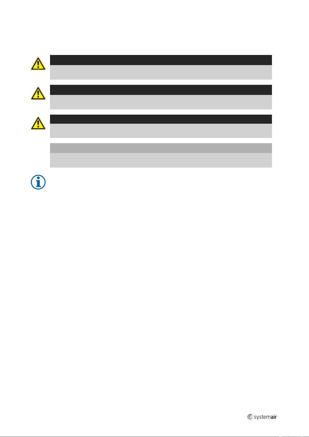
Danger
Direct hazard
Failure to comply with this warning will lead directly to death or to serious injury.
Warning
Potential hazard
Failure to comply with this warning may lead to death or serious injury.
Caution
Hazard with a low risk
Failure to comply with this warning may lead to moderate injuries.
Important
Hazard with risk of damage to objects
Failure to comply with this warning will lead to damage to objects.
General information |
1
Note:
Useful information and instructions
1.1.1 Instruction symbols
Instruction
♦ Carry out this action
♦ (if applicable, further actions)
Instruction with xed sequence
1. Carry out this action
2. Carry out this action
3. (if applicable, further actions)
2 Important safety information
Planners, plant builders and operators are responsible for the proper assembly and intended use.
♦ Read the operating instructions completely and carefully.
♦ Keep the operating instructions and other valid documents, such as the circuit diagram or motor instructions, with
the fan. They must always be available at the place of use.
♦ Observe and respect local conditions, regulations and laws.
♦ Only use the fan in a awless condition.
♦ Provide generally prescribed electrical and mechanical protective devices.
♦ During installation, electrical connection, commissioning, troubleshooting, and maintenance, secure the location and
premises against unauthorised access.
♦ Do not circumvent any safety components or put them out of action.
♦ Keep all the warning signs on the fan complete and in a legible condition.
♦ The device is not to be used by persons (including children) with reduced physical, sensory or mental capabilities, or
lack of experience and knowledge, unless they have been given supervision or instruction.
♦ Do not allow children to play with the device.
| 003
Page 6
Warranty
|
2
2.1 Personnel
The fan may only be used by qualified, instructed and trained personnel. The persons must know the relevant safety directives in order to recognise and to avoid risks. The individual activities and qualifications can be found in Table 1 Qual-
ifications, page 2.
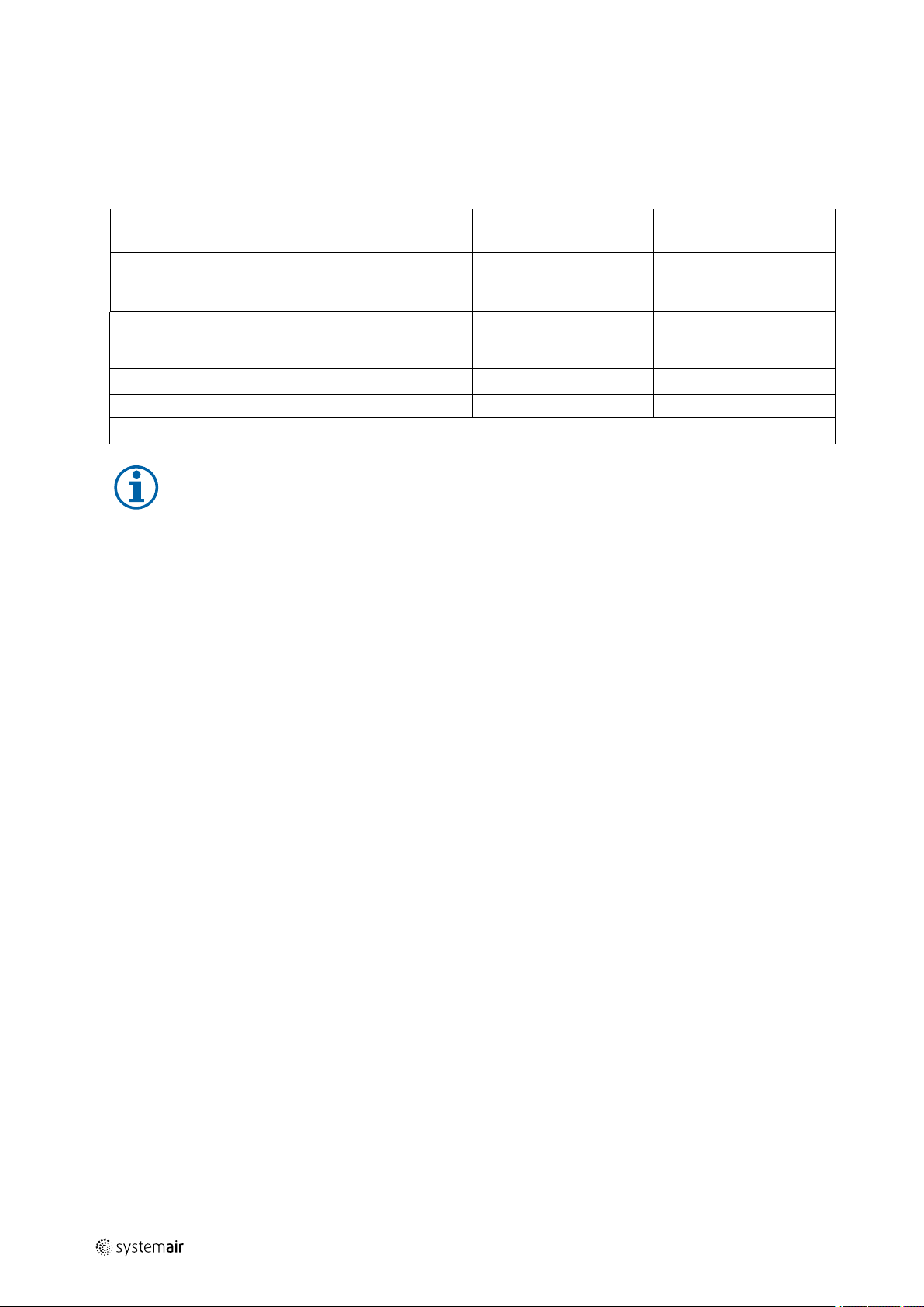
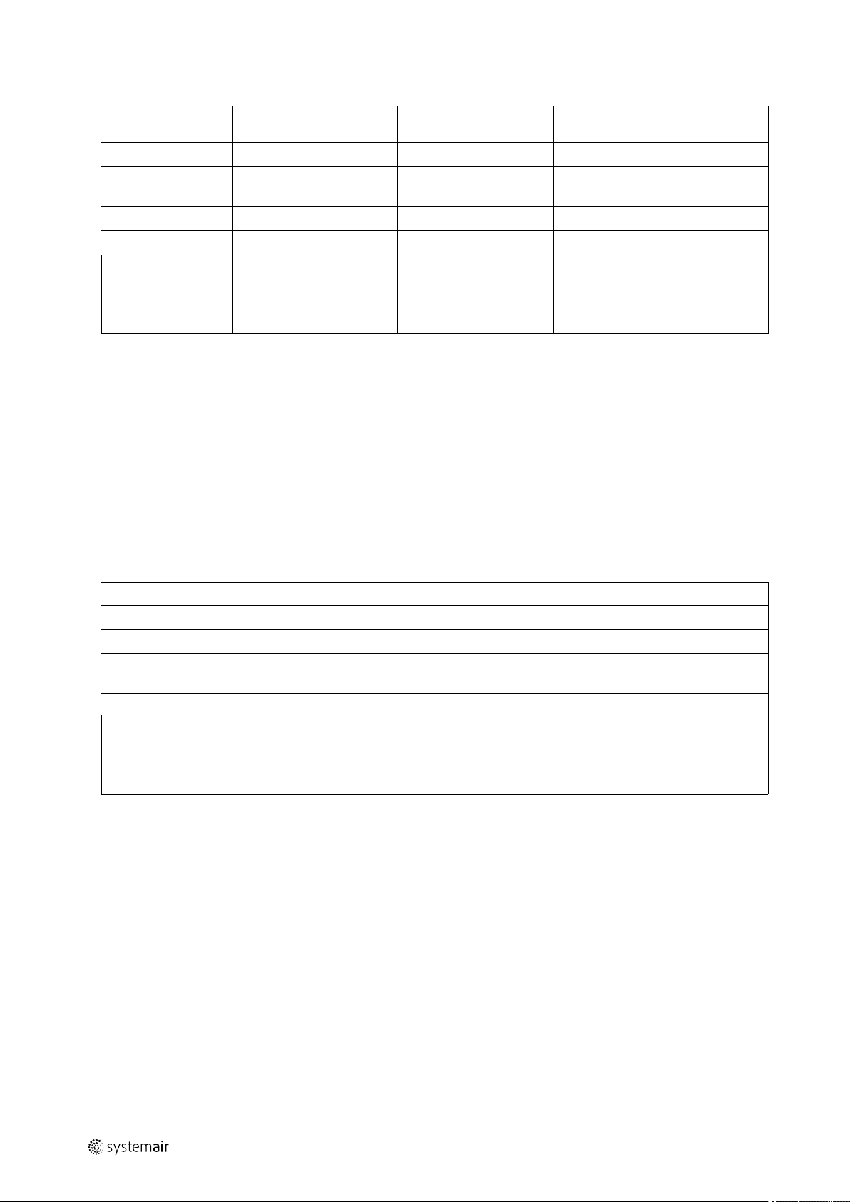
Table 1 Qualifications
Activities
Storage, operation,
transport, cleaning,
disposal
Electrical connection,
commissioning, electrical
disconnection
Installation, disassembly
Maintenance X X
Repair
Electrical expert or
matching qualification
X
Smoke extraction fans and EX fans only by agreement with Systemair.
Fitter or matching
qualification
Note:
The operator is responsible for ensuring that personnel are instructed and have understood the contents of
the operating instructions. If something is unclear, please contact Systemair or its representative.
2.2 Personal protective equipment
Wear protective equipment during all work in the vicinity of the fan.
• protective working clothes
• protective working shoes
• protective working gloves
• helmet
• goggles
• hearing protection
Trained personnel (see
following note)
X
X
2.3 5 rules of electrical safety
• Disconnect (disconnection of the electrical system from live components at all terminals)
• Prevent reactivation
• Test absence of voltage
• Ground and short-circuit
• Cover or restrict adjacent live parts
3 Warranty
The warranty for our products is determined by the contractual stipulations, our offers and our Terms and Conditions.
Warranty claims presuppose that the product is properly connected, operated according to data sheets and serviced as
needed. A correct commissioning report must also be presented upon request. Please find the commissioning report attached to this document.
4 Delivery, transport, storage
4.1 Safety information
Warning: Risk from rotating fan blades
♦ Prevent access by unauthorised persons by safety personnel or access protection.
Warning: Suspended loads
♦ Wear protective equipment during all work in the vicinity of the fan, details see 2.2 Personal protective equipment,
page 2.
♦ Do not walk under suspended loads.
| 003
Page 7
Delivery, transport, storage |
♦ Make sure that there is nobody under a suspended load.
4.2 Delivery
Each fan leaves our plant in an electrically and mechanically proper condition. We recommend transporting the fan to
the installation site in the original packaging.
Checking delivery
♦ Check completeness of the delivery.
♦ Check the packaging for transport damage.
Unpacking
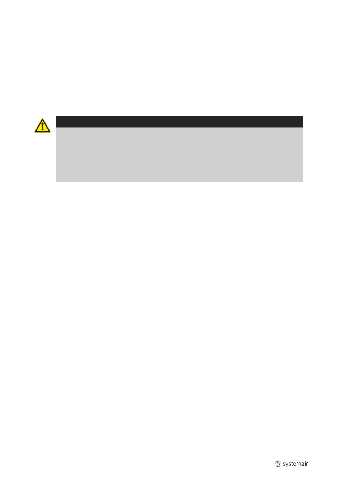
Warning
When opening the transport packaging, there is a risk of damage from sharp edges, nails, staples,
splinters etc.
♦ Unpack the fan carefully.
♦ Check the fan for obvious transport damage.
♦ Only remove the packaging shortly before assembly.
♦ Wear protective equipment during all work in the vicinity of the fan, details see 2.2 Personal protective
equipment, page 2.
3
4.3 Transport
4.3.1 Safety information
Warning: Electrical or mechanical hazards due to fire, moisture, short circuit or malfunction.
♦ Never transport the fan by the connecting wire, terminal box, rotor, protective grille, inlet cone or silencer.
♦ In open transport, please make sure that no water can penetrate into the motor or other sensitive parts.
♦ We recommend transporting the fan to the installation site in the original packaging.
Caution: If transported without care during loading and unloading, the fan may be damaged.
♦ Load and unload the fan carefully.
♦ Use hoisting equipment that is suitable for the weight to be hoisted.
♦ Observe the transportation arrows on the packaging.
♦ Use the fan packaging exclusively as transport protection and not as a lifting aid.
4.4 Storage
4.4.1 Safety information
Warning: Risk of injury and damage to the fan.
♦ Do not stack the fans on top of one another.
♦ Do not use transport packaging as hoisting aids.
♦ Use hoisting equipment that is suitable for the weight to be hoisted.
4.4.2 Preconditions
♦ Store the devices in a clean, dry and vibration-free environment.
♦ Storage temperature should be between –20°C and 60°C.
4.4.3 Long storage time
Storage more than 3 months
♦ Turn the rotor at least 10 revolutions once a month.
♦ Please ensure that the rotor is at a different position afterwards.
| 003
Page 8

Description
|
4
Storage more than 12 months
♦ We recommend an inspection by the after-sales service of Systemair before commissioning.
Test the motor windings:
♦ Measure the insulation resistance of each motor winding against grounding at 500 V DC. The insulation resistance
must be > 10 mΩ.
Measures for an insulation resistance < 10 mΩ:
1. If the motor has drain plugs, remove them to allow any moisture to drain and replace them when the motor windings
are suitably dry.
2. Dry the motor in a warm dry airflow (typically 40 degrees Celsius).
3. Measure the insulation resistance of each motor winding against grouding at 500 V DC.
4. Repeat the aforementioned steps until the measurement outcome > 10 mΩ.
Test the motor:
♦ Connect an ammeter to each phase of the motor.
♦ Switch the fan on and check the current consumption.
♦ Compare the current consumption with the nominal consumption on the name plate.
5 Description
5.1 General
• The fan conveys air in an axial direction from the intake side via the electric motor to the outlet side. (except AXCBF).
• The electrical connection is made through a terminal box installed on the outside of the housing (except AXCBF).
5.1.1 Sensors (optional)
Sensors can be connected to the fan to monitor the roller bearings and for vibration monitoring.
5.1.2 Standstill heating (optional)
The standstill heating starts when the motor switches off and vice versa.
5.1.3 Technical data of the fan
The technical data of the fan can be seen on the name plate or the data sheet.
5.1.4 Motor data
The motor data can be found on the name plate of the motor or in the technical documents of the motor manufacturer.
| 003
Page 9
5.1.5 Temperature types
Table 2 Types of fans
Description
|
5
Type
AXC/AXR
AXC (K)/AXR (K)
AXC (B)/AXR (B)
AXC (F)/AXR (F)
AJR/AJ8
AJR (K)/AJ8 (K)
AJR (B)/AJ8 (B)
AJR (F)/AJ8 (F)
IV 50, 85, 100
IV (B)
IV(F)
AXCBF- Thermo fans are equipped with an encapsulated motor, permanent operation temperature up to 200°C.
F250, F300, F400 according to DIN EN 12101–3
Diameter [mm]
315 — 1600
315 — 1600
315 — 1600
315 — 1600
315 — 400
315 — 400
315 — 400
315 — 400
50, 85, 100
50, 85, 100
Long-term
operation –20°
C...55°C
X
X X
X X
X X
X
X X
X X
X X
X
X X
X X
(K) 250°C/120
min.
(B) 300°C/120
min.
(F) 400°C/120
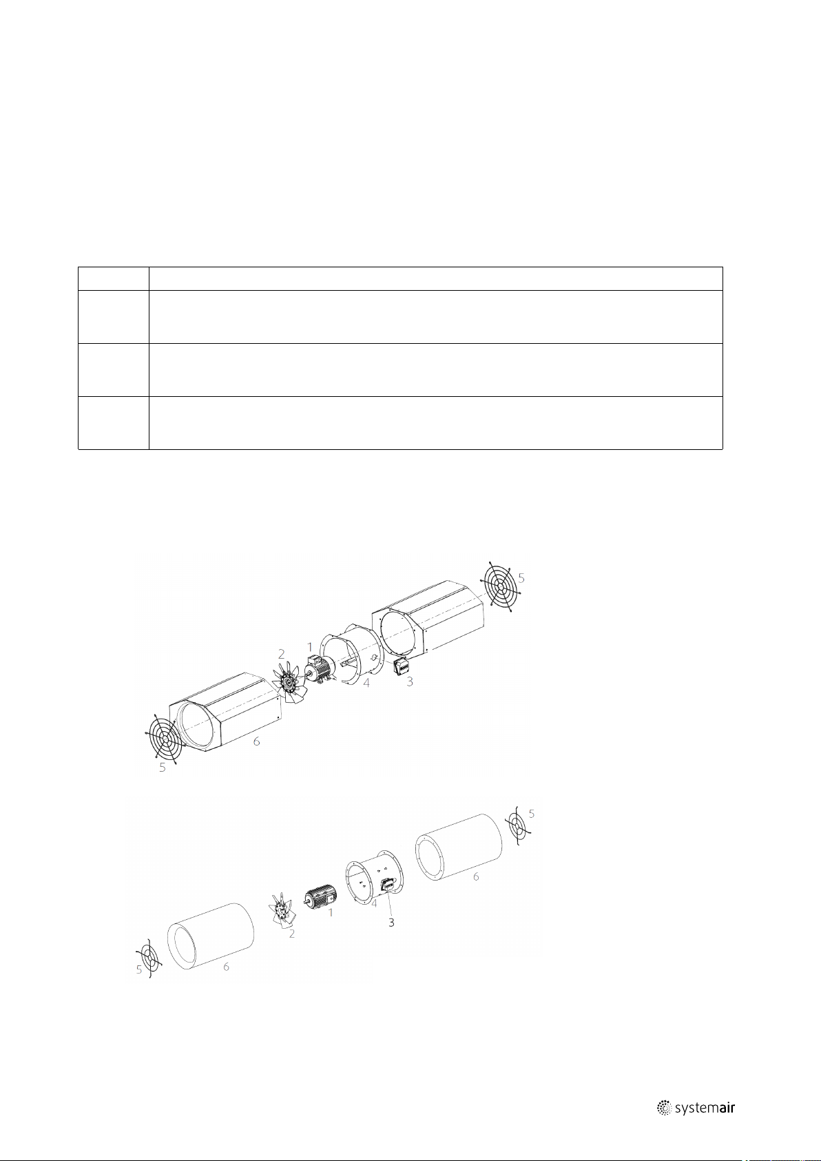
5.2 Description axial fans (AXR, AXC)
min.
• In B3 conventional motors, the motor bracket is made from galvanized steel sheet. B30 “pad mounted” motors are
fitted in the housing via threaded rods or a welded motor support.
• The motor with impeller is mounted to a sturdy supporting structure made of galvanized steel sheet.
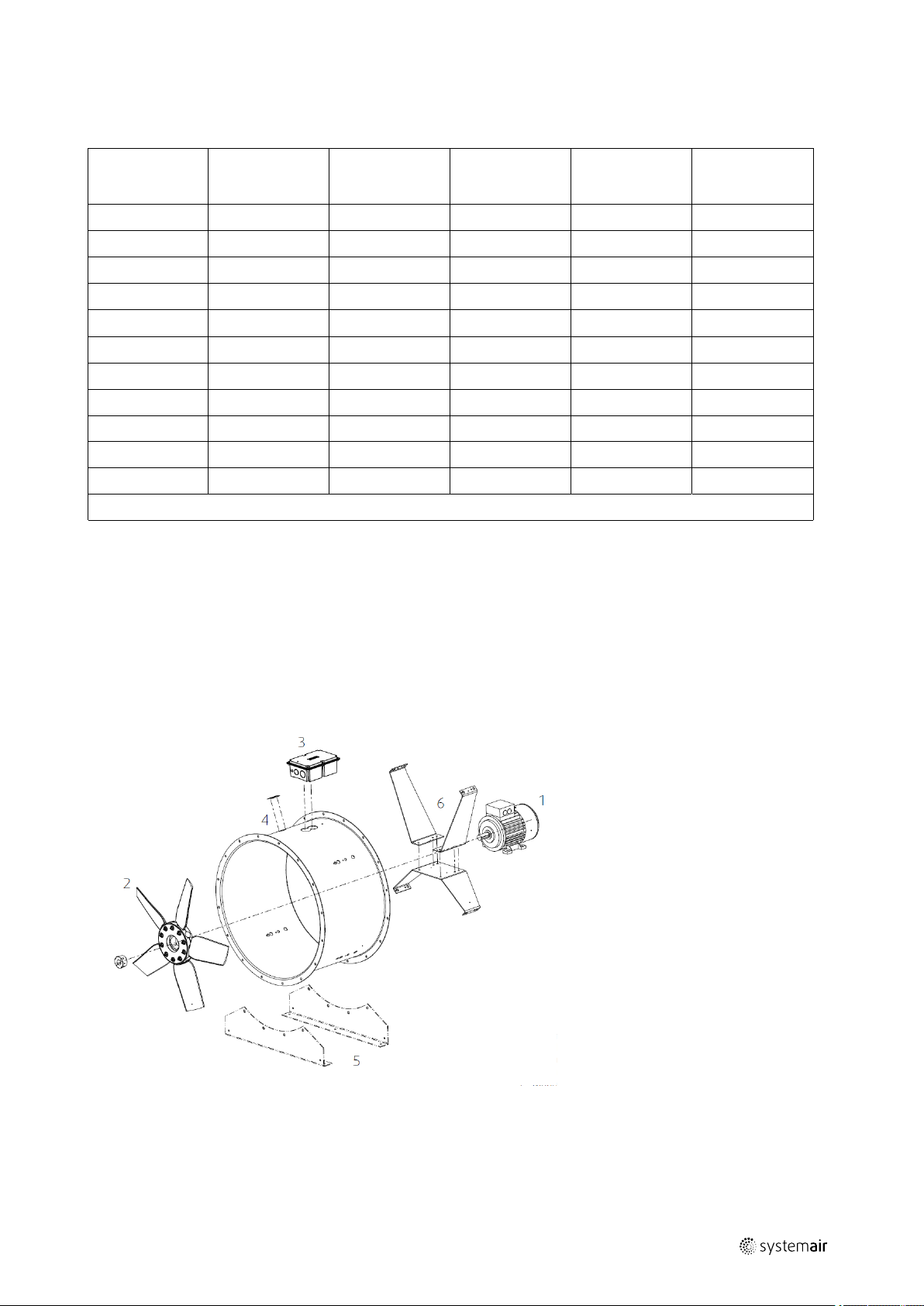
5.2.1 Construction
1 Motor
2
Impeller
3
Terminal box
4
Housing
5
Mounting feet
6
Motor brackets
| 003
Page 10
Description
|
6
5.2.2 Types
Table 3 Constructive features
Type
AXC
AXC-G
AXR
Constructive features
As a default, the fans are provided in protection class IP55, ISO F.
Fans constructed as garage version. Arrangement of two fans in series, switched behind one another.
The conveying direction can be reversed by switching the direction of rotation.
AXC(K),
AXR(K)
AXC(B),
AXR(B)
AXC(F),
AXR(F)
Table 4 Possible Combinations
AXC...-B
AXC...-G
AXC...-G-B
AXC...(B)-B
AXC...(B)-G Smoke extraction axial fan, 2 fans connected in series (2–stage)
AXC...(B)-G-B Smoke extraction axial fan, 2 fans connected in series (2–stage) inside a sound-isolated box
AXC...(F)-B
AXC...(F)-G Smoke extraction axial fan, 2 fans connected in series (2–stage)
AXC...(F)-G-B Smoke extraction axial fan, 2 fans connected in series (2–stage) inside a sound-isolated box
As a default, the fans are provided in protection class IP54/55, ISO H. The connection wire from the motor
to the terminal box is protected via an additional flexible metal hose. The standard motors (400 V type
B3) are without motor protection.
As a default, the fans are provided in protection class IP54/55, ISO H. The connection wire from the motor
to the terminal box is protected via an additional flexible metal hose. The standard motors (400 V type
B3) are without motor protection.
As a default, the fans are provided in protection class IP54/55, ISO H. The connection wire from the motor
to the terminal box is protected via an additional flexible metal hose. The standard motors (400 V type
B30) are without motor protection.
Axial fan, inside a sound-insulated box
Axial fan, 2 fans connected in series (2-stage)
Axial fan, 2 fans connected in series (2-stage) inside a sound-isolated box
Smoke extraction axial fan in sound-isolated box
Smoke extraction axial fan in sound-isolated box
| 003
Page 11
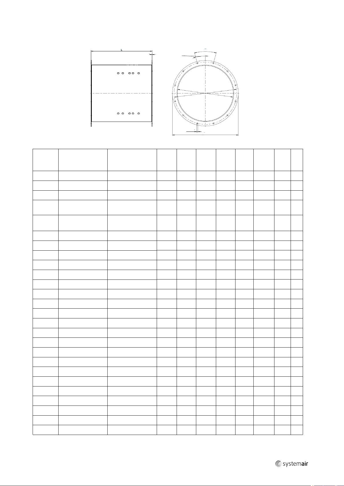
5.2.3 Dimensions
L
W
1/2 W
Ø B x T
ØDa
ØDi
ØTk
S
Description
|
7
Size
(AXC/
AXR)
315
355
400
450
500
560
560
630
630
710
710
710
800
800
900
900
1000
1000
1120
1120
1250
1250
1400
1400
1600
1600
Motor size B3/IEC Motor size B30/
IEC
71/80/90 80/90
71/80/90 80/90
71/80/90/100 80/90/100
71/80/90/100/
112
71/80/90/100/
112/132
80/90/100/112 80/90/100/112
132/160 132/160/180
80/90/100/112 80/90/100/112
132/160 132/160/180
80/90/100/112 80/90/100/112
132/160M 132/160
160L/180 160/180/200
90/100/112 90/100/112
132/160 132/160
100/112/132 100/112/132
160/180/20 160/180/200
100/112/132 100/112/132
160/180/200 160/180/200
132/160 132/160/180
180/200/220/250 200/225/250
132/160/180/200 132/160/180/200
225/250/280M 225/250/280
160/180/200/225 160/180/200/225
250/280/315 250/280
160/180/200/225 160/180/200/225
250/280/315 250/280
80/90/100/112
80/90/100/112/
132
Ø Di
[mm]
315 395 355 375 2.5 45° 10 8
355 435 395 375 2.5 45° 10 8
400 480 450 450 2.5 45° 12 8
450 530 500 500 2.5 45° 12 8
500 590 560 540 3.0 30° 12 12
560 650 620 500 3.0 30° 12 12
560 650 620 750 3.0 30° 12 12
630 720 690 500 3.0 30° 12 12
630 720 690 750 3.0 30° 12 12
710 800 770 500 3.0 22.5° 12 16
710 800 770 700 3.0 22.5 12 16
710 800 770 800 4.0 22.5 12 16
800 800 860 500 3.0 22.5 12 16
800 890 860 700 3.0 22.5 12 16
900 1005 970 640 4.0 22.5 15 16
900 1005 970 850 4.0 22.5 15 16
1000 1105 1070 640 4.0 22.5 15 16
1000 1105 1070 850 4.0 22.5 15 16
1120 1260 1190 700 4.0 18.0° 15 20
1120 1260 1190 1000 5.0 18.0° 15 20
1250 1390 1320 850 5.0 18.0° 15 20
1250 1390 1320 1050 6.0 18.0° 15 20
1400 1540 1470 950 5.0 18.0° 15 20
1400 1540 1470 1360 6.0 18.0° 15 20
1600 1740 1680 950 5.0 15.0° 19 24
1600 1740 1680 1360 6.0 15.0° 19 24
Ø Da
[mm]
Ø Tk
[mm]
L
[mm]
s
[mm]
w
[mm]
Ø B
[mm]
T
| 003
Page 12
Description
1
2
3
4
5
6 7
8
9
10
11
12
13
8
14
15
1
2
3
4
5
11
6
13
14
|
8
5.2.4 Accessories
Horizontal installation
Vertical Installation
1 SG
2 ESD-F
3 RSA
4
EV, EVH (F400)
5 MPR
6
7
REV (60°C)
REV (fire rated)
8 MP
9 MFA
10 SD
11 FSD
12 ZSD
Protection guard
Inlet cone
Silencer
Flexible connection
Mounting ring from size 315 to 1000
Isolator switch
Isolator switch
Mounting bracket from size 1120
Mounting foot
Rubber anti-vibration mounts
Spring anti-vibration mounts
Suspension spring anti-vibration
mounts
13 LRK
14 GFL
15 ABS
Air operated damper
Counter flange
Outlet cowl
Note:
Some accessories are also available for jet fans and AXCBF, please
check our online catalogue or contact Systemair.
| 003
Page 13
Description
|
5.3 Description Jet fans
5.3.1 Description AJR/AJ8
• In B3 conventional motors, the motor bracket is made from galvanized steel sheet. B30 “pad mounted” motors are
fitted in the housing via threaded rods or a welded motor support.
• The fan conveys air in an axial direction from the intake side via the electric motor to the outlet side.
• The silencers are equipped with protection grille made of galvanized steel.
• The acoustic insulation is non-flammable in accordance with DIN 4102 as described in directive 97/69 EC.
Table 5 Constructive features
AJR, AJ8
As a default, the fans are provided in protection class IP55, ISO F.
9
AJR(K),
AJ8(K)
AJR(B),
AJ8(B)
AJR(F),
AJ8(F)
As a default, the fans are provided in protection class IP54/55, ISO H. The wiring from the motor to the
terminal box is protected via an additional flexible metal hose. The standard motors (400 V type B3) are
without motor protection.
As a default, the fans are provided in protection class IP54/55, ISO H. The wiring from the motor to the
terminal box is protected via an additional flexible metal hose. The standard motors (400 V type B3) are
without motor protection.
As a default, the fans are provided in protection class IP54/55, ISO H. The wiring from the motor to the
terminal box is protected via an additional flexible metal hose. The standard motors (400 V type B30)
are without motor protection.
5.3.1.1 Construction
AJ8
AJR
| 003
1 — Motor
2 — Impeller
3 — Terminal box
4 — Housing
5 — Protective guard
6 — Silencer
Page 14

Description
|
10
5.3.1.2 Dimensions AJ8, AJR
AJ8
AJR
Size
AJ8 315 (B), (F)
AJ8 355 (B), (F)
AJ8 400 (B), (F)
ARJ 315 (B), (F)
ARJ 355 (B), (F)
ARJ 400 (B), (F)
H [mm] B [mm] E [mm] F [mm] L [mm]
365 550 635 678 1535
395 550 635 678 1695
445 600 684 727 1875
365 223 265 433 1535
465 243 305 473 1695
505 266 350 516 1875
5.3.2 Description IV fan
The induction fan is equipped with a radial fan with revision switch (optional).
5.3.2.1 Construction
1
Integrated deflector
2
Safety guard
3
Terminal box
4
Impeller
5 Motor 7 Fastener
6
Motor bracket
| 003
Page 15

5.3.2.2 Dimensions
Description
|
11
Size
50 790 834 870 1248 285 370 185 210 13.5
85 1140 1184 1220 1900 340 420 210 230 13.5
A [mm] B [mm] C [mm] D [mm] E [mm] F [mm] H [mm] I [mm] 6xØK
[mm]
5.4 Description AXCBF
Directly powered axial fan with motor outside the air flow. The fan can be run in permanent operation up to a conveying
media temperature of 200°C. Maximum ambient temperature 55°C. Housing flanges on both sides with bores according to eurovent 1/2 standard. B3 conventional motors with add-on terminal box.
5.4.1 Construction
1 — Motor
2 — Impeller
3 — Housing
4 — Mounting feet
5 — Motor bracket
| 003
Page 16

Description
F
A
B
C
D
H
I
I/2
E
B
A
C
I/2
I
H
|
12
5.4.2 Dimensions
Size 250 — 500 Size 630 — 800
Size
A [mm] ØB [mm] ØC [mm] ØD [mm] ØF [mm] ØH [mm]
I
250 535 448 328 250 280 10 4x90°
315 535 452 385 320 355 10 8x45°
400 625 585 480 401 450 10 8x45°
500 660 695 590 504 560 12 12x30°
630 790 728 634
800 880 890 797
-
-
690 12 12x30°
860 12 16x22.5°
5.5 Intended use
• The maximum admissible operating data on the name plate apply to an air density of 1.2 kg/3³ (sea level) and a
maximum air humidity of 80%.
• The temperature of the air transported through the fan must not exceed 55°C/131°F nor be lower than -20°C/-4°F.
• For the temperature resistance of the smoke extraction fans (K), (B), (F), which can also be used to extract CO, please
refer to the name plate (e.g. 300°C/120 min).
• The standard motors are suitable for operation with frequency converters.
5.5.1 Intended use axial fans
• The axial fans of the series AXC/AXR/AXCBF in the versions G (K), (B), (F) are intended for installation in ventilation
systems.
• The axial fans of the series AXC/AXR/AXCBF are ready-to-use products and are used as components for ventilation
devices, machines and systems. These fans can be used to extract, draw in or convey air.
• The fans can be installed both in duct systems and also with free suction via an inlet cone and a suction-side contact
protection grille. Free discharge via a contact protection grille is also possible.
5.5.2 Intended use jet fans
• The model AJ8, AJR and IV jet fans are intended for installation in underground and above-ground parking structures,
to facilitate ventilation and smoke extraction (K), (B), (F).
• For optimum operation, the jet fan must be suspended horizontally from the ceiling in such a position that intake and
outlet are unobstructed.
5.6 Incorrect use
Use the fans only for the requirements described in “intended use” and within the limits for use stated on the name
plate.
• The fan is not suitable for intake of aggressive media or media with a dust content so high that dust deposits on the
impeller or fan housing can affect the operation of the fan.
• The fan must not be installed in hazardous areas (areas with a potentially explosive atmosphere).
• The motors cannot be voltage controlled.
| 003
Page 17
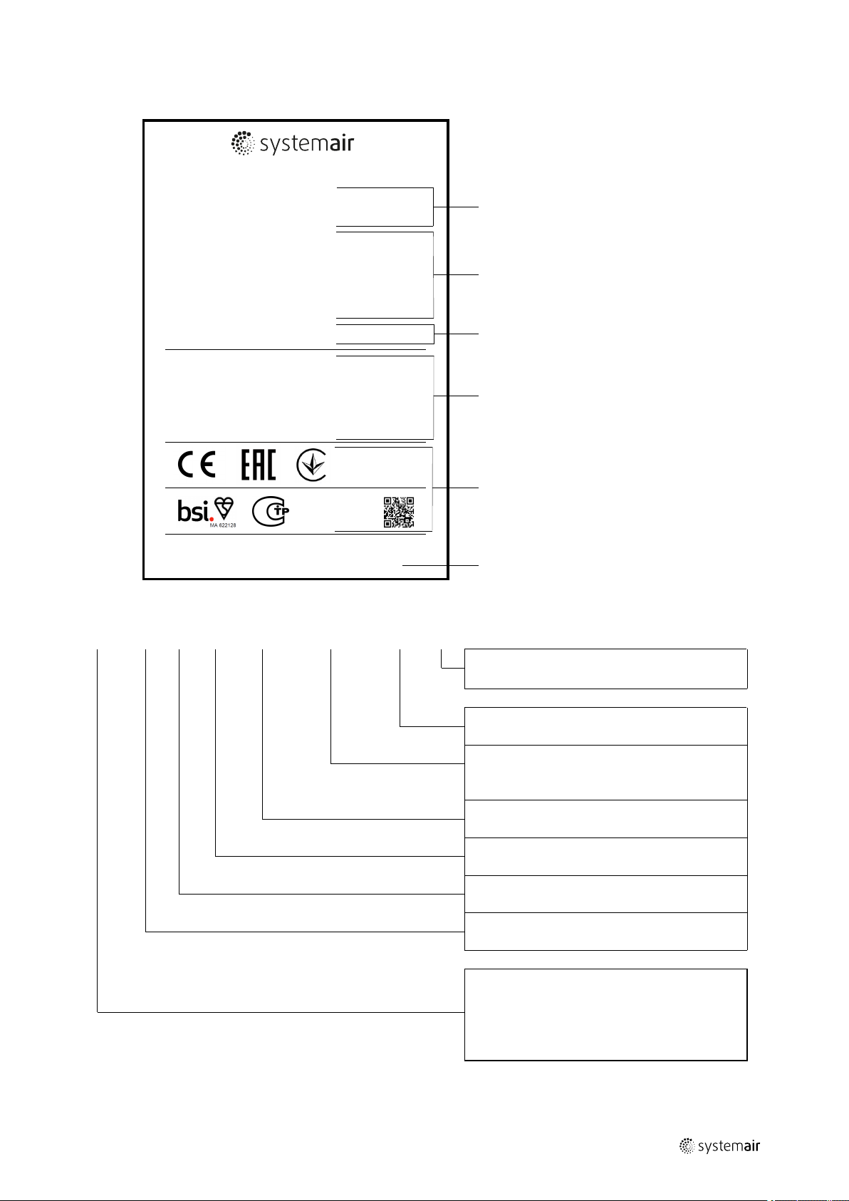
6 Name plate and type key
Type: AXC 400-7/10°-2 (F)
Manufacturing order no.: 1002888063
Manufacturing date: 03/2017
Made in: Germany
Voltage: 230 / 400 V Y
Frequency: 50 Hz
Nominal power at shaft (P2): 0,75 kW
Current: 2,95 / 1,69 A
Insulation class: H
Enclosure class, motor: IP55
Fan impeller speed: 2850 1/min
Weight: 36 kg
Max. temperature of transported air: 55 °C - 400 °C/2h
Number of certificate: 0036-CPR-RG04-11
EN 12101-3 (2015)
Powered Smoke and Heat Control ventilator
Systemair GmbH - Seehöferstraße 45 - 97944 Boxberg - Germany
Values for the fan unit at optimal energy efficiency point,
determined without speed control:
η: 48,2 % Pitch angle: 14°
V: 11.105 m³/h psf: 574 Pa
P1: 3,67 kW RPM: 2940
Measurement cat. / Efficiency cat.: A / Static
Efficiency grade: (N38) N= 51,0
This Powered Smoke and Heat Control ventilator shall be installed as per the manufacturer's instruction.
Installation and Operating Instructions are within the delivery.
20
1
2
3
4
5
6
Name plate and type key |
1
General data
2
Technical data
Temp./Time information/
3
only listed on smoke
extraction fans
4
ErP data
Certifications and QR—
5
Codes
6
Manufacturer Address
13
Table 6 Type key
AXC 400 -7
/10°* -2*
(-)(K), (B), (F)
-* —**
TR — Reversible
No sign — Uni-directional
-G – 2 fans in series
-B — Axial fan with insulated box
Temperature- Time information (smoke
extraction fan), see 5.1.5 Temperature types,
page 5
Number of poles
Blade angle
Number of blades
Nominal diameter of the fan
AXC
AXR
AJR
AJ8
Axial fan
Axial fan — reversible
Circular jet fan
Octagonal jet fan
*only AXC and AJ // **only AJR and AJ8
| 003
Page 18

| Installation
14
Table 7 AXCBF Type key
AXCBF 500– D2 20° IE2
Axial fan bifurcated Nominal diameter of
the fan
Table 8 IV Type key
IV 50– 4
Induction fan Thrust 50N Number of poles
3-phase motor 2–
pole
Blade angle International
efficiency
-
Temperature- Time
information (smoke
extraction fan), see 5.1.5
Temperature types, page 5
7 Installation
7.1 Safety information
Danger: Risk that the fan does not work in case of fire.
♦ Spring vibration mounts made from unsuitable materials do not fulfil their function! For smoke extraction fans (K),
(B) and (F) only use spring vibration mounts made of steel!
♦ Use installation material with fire resistance classes that meet temperature requirements.
Warning: Danger from falling fan or fan parts.
♦ Check the surface before installation for load bearing capacity.
♦ Consider all static and dynamic loads when selecting hoisting equipment and fastening components.
♦ Tighten all screw-type connections according to the data, see Table 9 Tightening torques according to DIN 13, page
15.
General safety information
♦ Installation may only be carried out by adequately qualified persons, details see Table 1 Qualifications, page 2.
♦ Wear protective equipment during all work in the vicinity of the fan, details see 2.2 Personal protective equipment,
page 2.
♦ Abide by the system-related conditions and requirements of the system manufacturer or plant constructor.
♦ Safety elements may not be dismantled, circumvented or deactivated.
♦ Move the impeller of the fan by hand before you install it in order to check whether that moves freely.
♦ Provide the fan at least with an IP 20 protective grille, if the fan is not installed in a duct system.
♦ Prevent the possibility of foreign bodies being drawn in.
♦ To reduce transmission of vibration to the duct system, we recommend flexible connections from our accessory
range, see 5.2.4 Accessories, page 8.
♦ Bear in mind that parts of the impeller may protrude out of the fan housing.
7.2 Preconditions
• Ensure that the fan and all its components are undamaged.
• Ensure that the information on the name plates (fan and motor) matches up with the operating conditions.
• Ensure that there is enough space to install the fan.
• Protect against dust and moisture when installing.
• Fit the fans in such a way that there is sufficient access for troubleshooting, maintenance and repair.
| 003
Page 19

7.3 Tightening torques of screw-type connections according to DIN 13
Table 9 Tightening torques according to DIN 13
Installation |
15
Screw size
Thread
M6 10 9 10 15 18 8
M7 11+12 14 17 25 28 14
M8 13+14 22 26 35 42 21
M10 15+17 42 50 71 85 40
M12 19+21 74 87 123 147 70
M14 22+23 117 138 194 235 110
M16 24+26 178 210 299 358 159
M18 27 245 289 412 490 231
M20 30 348 412 579 696 330
M22 32 471 559 785 941 447
M24 36 598 711 1000 1196 569
M27 41 888 1049 1481 1775 839
M30 46 1206 1422 2010 2403 1138
M33 50 1628 1932 2716 3266 1546
M36 55 2099 2481 3491 4197 1985
M39 60 2716 3226 4531 5443 2581
M42 65 3364 3991 5609 6727 3193
Key width
SW
6.9 M [Nm] 8.8 M [Nm] 10.9 M [Nm] 12.9 M [Nm] Aluminium
hubs [Nm]
7.4 Mounting feet
Depending on the kind of fan and the construction size, mounting feet are either included in the delivery or available as
accessories. If you are not sure, check the online catalogue or contact Systemair.
7.5 Avoid resonance frequencies
Important
Risk of damage to the fan due to resonance frequencies
♦ The minimum fan speed should be double the resonance frequency of the anti-vibration system
(vibration dampers).
♦ To avoid resonance frequencies, see 8.5 Frequency converter (if used), page 23.
7.5.1 Vibration dampers
Important
Risk of damage to the fan due to incorrect vibration dampers
♦ Use the vibration dampers suitable for the respective weight.
♦ Use the vibration dampers with fire resistance classes that match the respective application.
7.6 Lifting and positioning
The weight of the fan units varies depending on the motor size and accessories. As a result, the fan unit can also be
very bulky and heavy. You can find precise information on the name plate or the data sheet.
| 003
Caution
Risk of parts falling down
♦ When fitting the fan, pay attention to its weight and the weight of the components.
Page 20
| Installation
3
min. 2,5xD
3
1
2
min. 2,5xD
16
Lifting
♦ Lift the fan unit slowly and carefully.
♦ Use hoisting gear permitted for the weight of the fan.
♦ Attach the hoisting equipment to flanges and foot bores or at the marked places.
♦ Use transport equipment (e.g. lifting eyes) if available.
♦ Please observe the marking “oben/top” on the fan.
Positioning
♦ Observe the arrows on the name plate or the housing of the fan. They show the direction of rotation and air flow.
♦ Position the fan unit so that it is standing in the planned direction of flow.
♦ Provide enough free space for inspection and maintenance work on the fan unit.
7.6.1 Anchor the fan
Anchor
♦ Use suitable fittings.
♦ Screw the fittings with the correct tightening torques, see Table 9 Tightening torques according to DIN 13, page 15
♦ If you are not sure, contact Systemair.
7.7 Installation axial fans/AXCBF
Installation is possible in any mounting position. From size 1250 and above, please contact Systemair if the mounting
position should be different to horizontal or vertical.
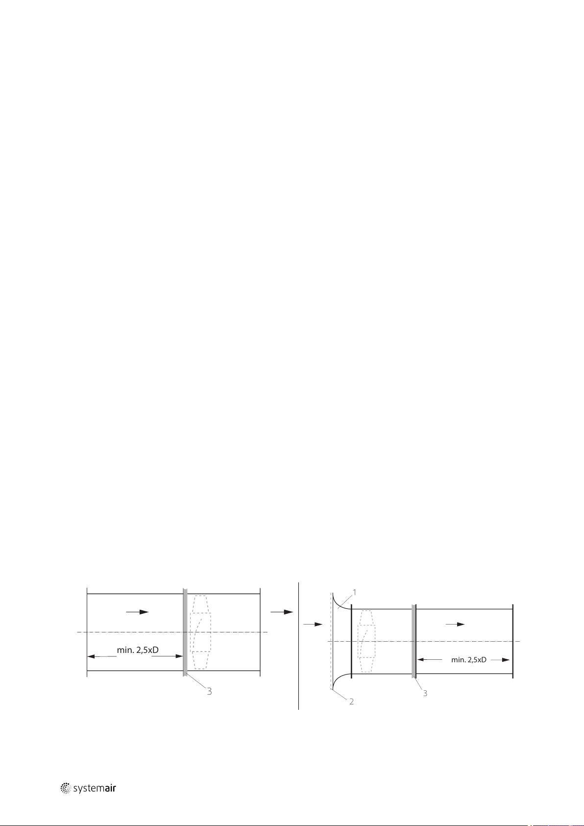
7.7.1 Installation of the ventilation system
7.7.1.1 Preconditions
♦ The air flow of the fan must be able to open the air operated damper (LRK).
7.7.1.2 Installation duct
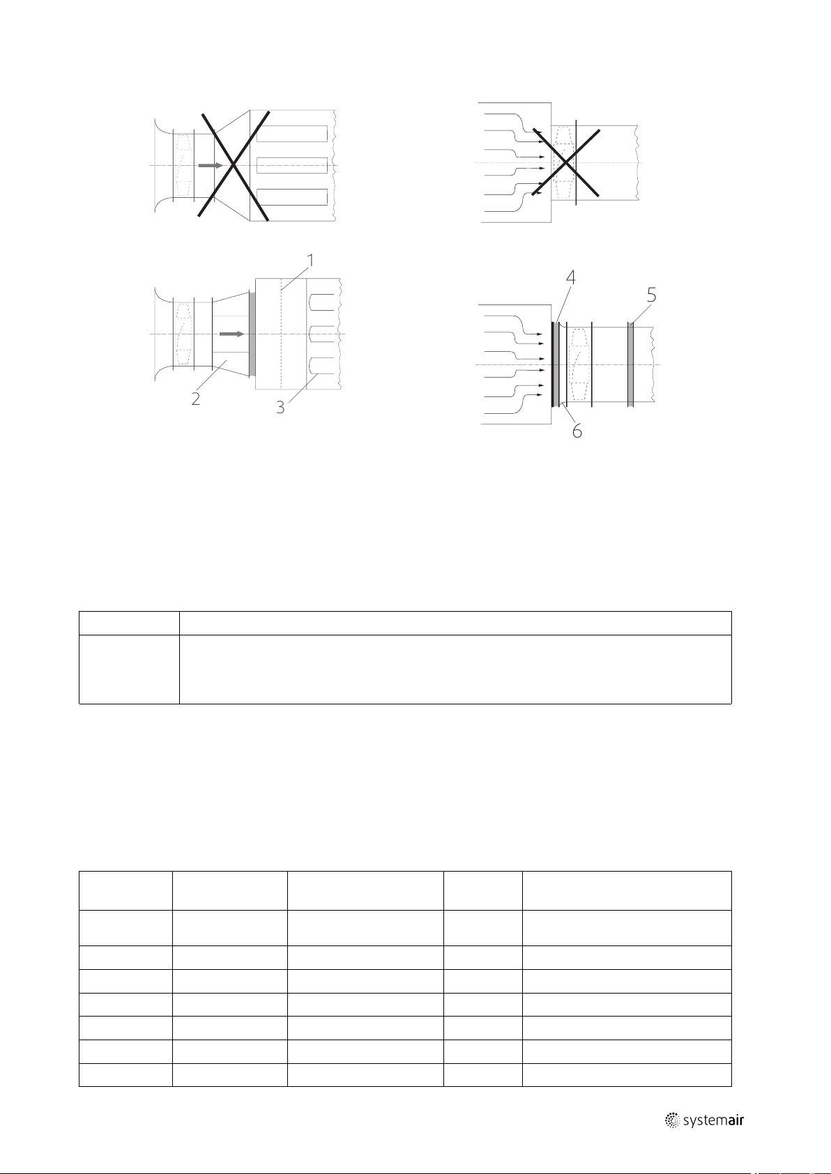
♦ Do not place a duct bend directly before or after the fan!
• This can cause damage to the bearings or other parts of the fan.
• The duty point may not be reachable.
• The fan may make noise.
♦ Ensure a direct, smooth and constant air flow to the device. Ensure a free exhaust, see the following pictures.
♦ Install an inlet cone or a channel section with a length of at least 2.5 x D
♦ To reduce transmission of vibration to the duct system, we recommend flexible connections from our accessory
range, see 5.2.4 Accessories, page 8.
D = nominal diameter
1
Inlet cone
2
Protective guard
3
Flexible connection
| 003
Page 21
Installation |
min. 1xD
1xD
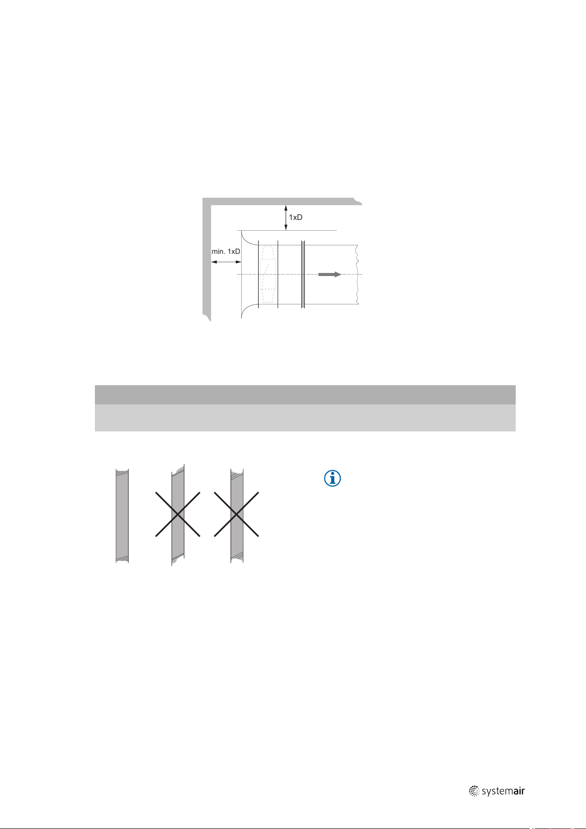
7.7.2 Distance from the wall/ceiling
♦ Ensure enough distance between the ceiling and the wall.
• The duty point may not be reachable.
• The fan may make noise.
If the minimal distances are not possible for construction reasons, install a deflector in front of the fan in a way that en-
sures a direct, smooth and constant flow of air. On the pressure side, provide a duct with a length of at least 2.5xD in order to reach the duty point. Contact with rotating parts must be ruled out at all times – either by ducts of a
corresponding length or by protective grids.
D = Nominal diameter
17
distance wall/ceiling
7.7.3 Installation of flexible connections
Important
Increasing noise emission
♦ Do not install the flexible connections at an angle.
Note:
When fitting the flexible connections,
make sure that they are fitted according
to the installation length (Table 10
Flexible connections — Installation length,
page 18), without compression or tensile
strain. They must not be used to
compensate any lack of precision in the
assembly.
| 003
Page 22

| Installation
LB
18
Table 10 Flexible connections — Installation length
Size
315
355
400
450
500
560
630
710
800
900
1000
1120
1250
1400
1600
EV (-25...70°C) EVH (400°C/2h)
LB full length
[mm]
157 (+/-5)
157 (+/-5)
157 (+/-5)
157 (+/-5)
157 (+/-5)
157 (+/-5)
157 (+/-5)
157 (+/-5)
157 (+/-5)
157 (+/-5)
157 (+/-5)
157 (+/-5)
157 (+/-5)
157 (+/-5)
157 (+/-5)
LE Installation
length [mm]
LB — 10
LB — 10
LB — 10
LB — 10
LB — 10
LB — 10
LB — 10
LB — 10
LB — 10
LB — 10
LB — 10
LB — 15
LB — 15
LB — 15
LB — 15
LB Overall
length [mm]
147 (+/-5)
147 (+/-5)
147 (+/-5)
147 (+/-5)
147 (+/-5)
147 (+/-5)
147 (+/-5)
147 (+/-5)
147 (+/-5)
147 (+/-5)
147 (+/-5)
147 (+/-5)
147 (+/-5)
200 (+/-5)
200 (+/-5)
LE Installation
length [mm]
LB — 10
LB — 10
LB — 10
LB — 10
LB — 10
LB — 10
LB — 10
LB — 10
LB — 10
LB — 10
LB — 10
LB — 15
LB — 15
LB — 15
LB — 15
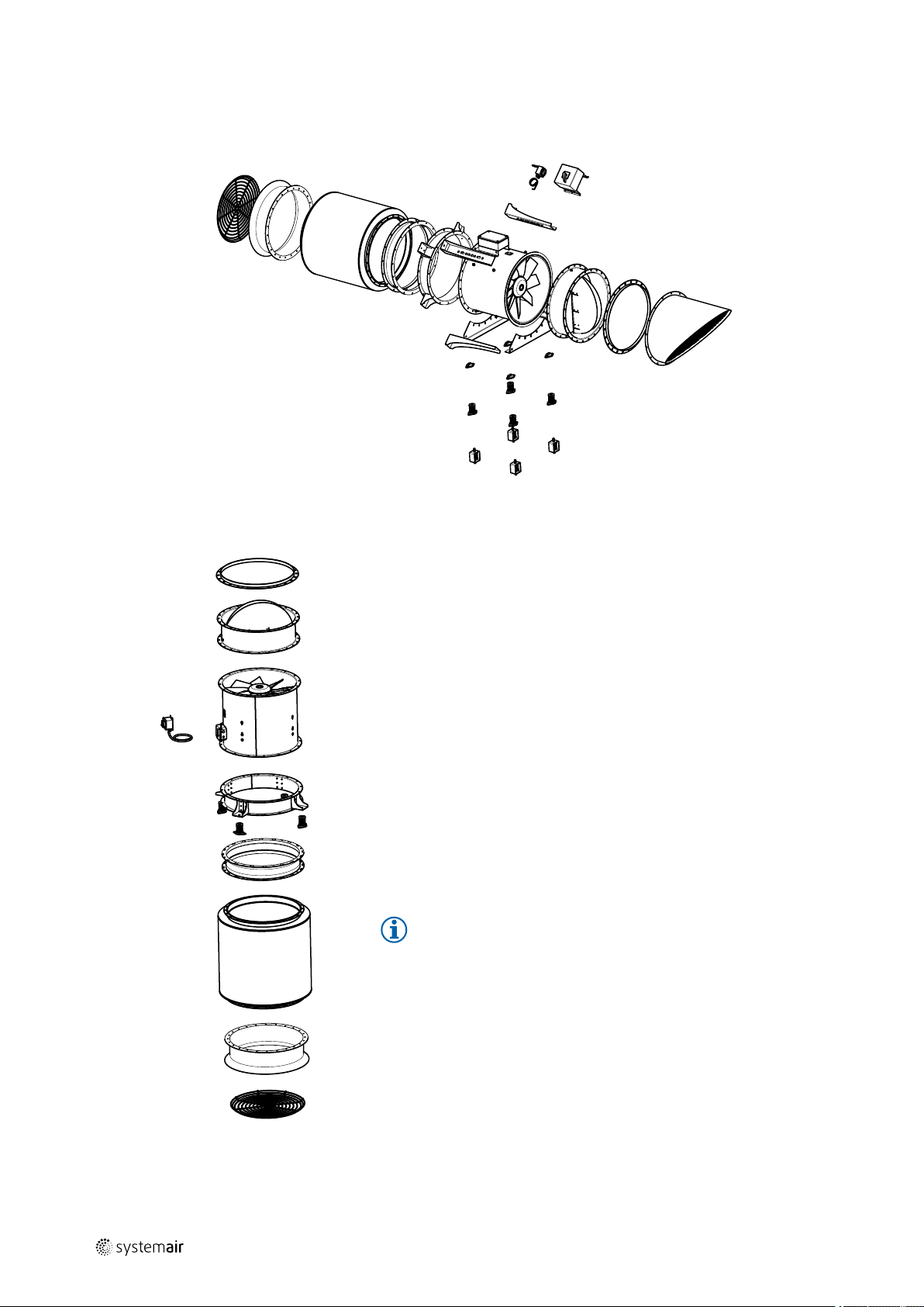
7.7.4 Installation silencer
♦ Ensure correct installation of the silencer.
• This can cause damage to the bearings or other parts of the fan.
• The duty point may not be reachable.
• The fan may make noise.
♦ Ensure a direct, smooth and constant air flow to the device. Ensure a free exhaust, see the following pictures.
♦ To reduce transmission of vibration to the duct system, we recommend flexible connections from our accessory
range, see 5.2.4 Accessories, page 8.
| 003
Page 23
Installation |
3
1
2
6
4
5
19
1
Plenum box with perforated sheet (flow straightener)
2
Deflector with inner core
3
Baffles
4
Flexible connection
5
Flexible connection
6
Inlet cone
7.7.5 Special points of installation
Type
AXC (B), (K), (F)
AXR (B), (K), (F)
Special points for assembly
Smoke exhaust fans are suitable for installation inside or outside a smoke reservoir, as well as
outdoors. If positioned outside the smoke reservoir, but still inside the building, the fan must be
provided with heat insulation by the customer. The heat insulation must be provided with fire
proof material L120 according to DIN 4102-4.
7.7.6 Air gap
Ensure that the air gap between the housing and the impeller is complied with.
♦ Check if the air gap complies with the table.
♦ Do not install the fan if the gap in the table below is not complied with.
♦ Contact Systemair.
Table 11 Air gap AXC/AXR
AXC/AXR
(K) + (B)
Nominal
width
315
355
400
450
500
560
Housing tolerance
+/– 1mm
+/– 1mm
+/– 1mm
+/– 1mm
+/– 1mm
+/– 1mm
AXC/AXR (Standard
temperature)
Rotor Ø Rotor Ø Rotor Ø
312 mm 310 mm 306 mm
352 mm 350 mm 346 mm
397 mm 395 mm 391 mm
445 mm 443 mm 440 mm
495 mm 493 mm 489 mm
555 mm 551 mm 547 mm
AXC/AXR (F)
| 003
Page 24

| Installation
20
Air gap AXC/AXR cont'd
630
710
800
900
1000
1120
1250
1400
1600
+/– 1mm
+/– 1mm
+/– 1mm
+/– 1mm
+/– 2mm
+/– 2mm
+/– 2mm
+/– 2mm
+/– 3mm
625 mm 621 mm 615 mm
705 mm 701 mm 695 mm
795 mm 789 mm 783 mm
895 mm 889 mm 881 mm
992 mm 988 mm 978 mm
1112 mm 1105 mm 1095 mm
1242 mm 1234 mm 1223 mm
1386 mm 1383 mm 1370 mm
1583 mm 1581 mm 1567 mm
7.8 Installation jet fans AJR, AJ8 and IV
Always install in a horizontal position.
7.8.1 Air gap
Ensure that the air gap between the housing and the impeller is complied with.
♦ Check if the air gap complies with the table.
♦ Do not install the fan if the gap in the table below is not complied with.
♦ Contact Systemair.
Table 12 Air gap
Nominal
width
315
355
400
Housing tolerance
+/– 1 mm
+/– 1 mm
+/– 1 mm
AJR/AJ8 (Standard temperature) AJR/AJ8
(K) + (B)
Rotor Ø Rotor Ø Rotor Ø
312 mm 310 mm 306 mm
352 mm 350 mm 346 mm
397 mm 395 mm 391 mm
AJR/AJ8 (F)
7.8.2 Deflector
For optimal guidance of the air current, a deflector made of galvanized steel sheet can be mounted on the pressureside silencer (accessory).
The deflector as accessory for AJR/AJ8 is delivered in a separate package.
♦ Before installing the jet fan, fasten the deflector on the silencer of the pressure side (see arrow).
♦ Position the deflector fins so that after fastening the jet fan to the ceiling, the air flow is directed downwards at a
10° angle. It may be possible to readjust the fans afterwards depending on the structures located in the immediate
vicinity, such as girders.
| 003
Page 25

Electrical connection |
A
B
C
D
A — Position the fins to the specified angle and secure
them with 4.2 x 13 self-drilling screws..
B — Use M4 x 12 self- locking screws to fasten the
deflector to the fan.
C— Fasten the deflector with an M6 x 40 screw, an M6
nut and a Ø6 serrated washer.
D— Position the fins to specified angle and secure them
with 4.2 x 13 self-drilling screws.
21
8 Electrical connection
8.1 Safety information
Warning: Danger from electrical voltage.
♦ Observe the 5 rules of electrical safety, see 2.3 5 rules of electrical safety, page 2.
♦ Prevent the ingress of water into the connection box.
♦ Electrical connection may only be carried out by adequately qualified persons, details see Table 1 Qualifications, page
2.
♦ Wear protective equipment during all work in the vicinity of the fan, details see 2.2 Personal protective equipment,
page 2.
8.2 Preconditions
♦ Observe and respect local conditions, regulations and laws.
♦ Abide by the system-related conditions and requirements of the system manufacturer or plant constructor.
♦ Safety elements may not be dismantled, circumvented or deactivated.
♦ Install a circuit breaker in the permanent electrical installation, with a contact opening of at least 3 mm at each pole.
8.3 Protecting the motor
Important
| 003
Damage as a result of motor overheating.
The motor can overheat and be destroyed if the thermo-contacts or cold conductor have not been
functionally connected.
♦ Always connect thermo-contacts or cold conductors to a motor protection device.
Page 26
| Electrical connection
22
Table 13 Motor protection
Type
AXC,-B,-D,-G,-P By customer PTC
AXC (B),(F),(K)
AXR (B),(F),(K)
AXR By customer PTC
AXCBF By customer PTC
AJ8 (B), (K), (F)
AJR (B), (K), (F)
AJ8
AJR
Motor protection
By customer- must be
bypassed in case of fire
By customer- must be
bypassed in case of fire
By customer PTC
Thermal protection,
standard
without (PTC optional)
without (PTC optional)
Speed regulation
Possible via frequency converter
Possible via frequency converter—
must be bypassed in case of fire
Possible via frequency converter
Possible via frequency converter
Possible via frequency converter—
must be bypassed in case of fire
Possible via frequency converter
8.4 Connection
♦ Check that the data on the name plate matches the connection data.
♦ Complete the electrical connection according to the circuit diagram.
♦ Lay the connection cables in the terminal box in such a way that allows the cover of the terminal box to be closed
without resistance.
♦ Use all of the locking screws.
♦ Insert the screws by hand to avoid damaging the thread.
♦ Tighten all glands well in order to guarantee protection class IP.
♦ Screw the lid of the terminal box/REV switch evenly tight.
♦ Connect the cable end in a dry environment!
Type
AXC,-B,-D,-G
AXR
AXC (B), (K), (F)
AXR (B), (K), (F)
AXCBF
AJ8 (B), (K), (F)
AJR (B), (K), (F)
AJ8
AJR
Electrical Connection
Connection via terminal box. The terminal box is fitted on the outside of the housing.
Connection via terminal box. The terminal box is fitted on the outside of the housing.
Connection via terminal box. The terminal box is fitted on the outside of the housing.
Connection via terminal box. The terminal box is attached to the motor.
Connection via terminal box. The terminal box is fitted on the outside of the housing.
Connection via terminal box. The terminal box is fitted on the outside of the housing.
| 003
Page 27

8.4.1 Connection diagrams
3–phase motor with
optional thermal
contacts or cold
conductor.
Electrical connection |
23
Dahlander motor
with optional
thermal contacts or
cold conductor.
Motor, 2 windings
with optional
thermal contacts or
cold conductor.
8.5 Frequency converter (if used)
Risk from resonant frequencies when using frequency converter.
♦ Only operate the fan outside these speed ranges.
♦ Pass through these speed ranges so quickly that any vibration cannot exceed the admissible resonant frequency
values.
♦ For variable-speed fans, use a permanent vibration monitoring for long-term safe operation.
♦ Observe the operating instructions of the frequency converter.
| 003
Page 28

Commissioning
|
24
Commissioning of the frequency converter
♦ Install the fan and frequency converter as near as possible to one another.
♦ Use shielded cables.
♦ All components (fan, frequency converter and motor) must be grounded.
♦ We recommend using all-pole sinus filters.
Operation of the frequency converter
♦ Avoid running the fan via the frequency converter below 10 Hz.
♦ If controlling the fans via a frequency converter, provide thermal protection in the form of a PTC resistor or thermal
contacts (TC) in the motor.
♦ Starting time: min. 60 sec.
8.6 Protective grounding wire
• The terminal box is provided with a labeled grounding connection.
• The protective grounding must have a cross-section equal to or greater than that of the phase conductor.
8.7 Residual current circuit breaker
♦ Observe and respect local conditions, regulations and laws.
♦ If controlling the fans via a frequency converter, provide thermal protection in the form of a PTC resistor or thermal
contacts (TC) in the motor.
9 Commissioning
9.1 Safety information
♦ Commissioning may only be carried out by adequately qualified persons, details see Table 1 Qualifications, page 2.
♦ Wear protective equipment during all work in the vicinity of the fan, details see 2.2 Personal protective equipment,
page 2
9.2 Preconditions
♦ Installation and electrical connection have been correctly performed.
♦ Residual material from installation and foreign objects have been removed from the fan and ducts.
♦ Inlet and outlet are free.
♦ Safety devices have been fitted.
♦ Ground cable is connected.
♦ Cable glands are tight.
♦ Nominal current (from the name plate) is not exceeded.
♦ Data on the name plate corresponds with the connection data.
9.3 Tests before activation
♦ Check that safety elements and protective grilles are securely fastened.
9.4 Tests when activated
1. Before switching the fan on, check for externally visible damage and ensure that the protective equipment functions
properly.
2. Switch the fan on.
3. Checks:
♦ Direction of rotation/conveyance. The direction of rotation always applies looking at the rotor
♦ Smooth running (any vibrations and noise)
♦ Current consumption
♦ Tightness of all connections
| 003
Page 29

Operation
4. Switch the fan off.
9.5 Commissioning of speed-controlled fans
Check the fan for vibrations at all normal operation speeds during commissioning. Determine and evaluate vibrations
on the housing and bearing areas in accordance with DIN ISO 14694 depending on motor power and positioning.
Measurable vibration velocities depend e.g. on following factors:
• positioning
• bottom section/foundation state
• flow conditions
The working point of the fan, as well as used external devices and accessories, also influence the running
characteristics.
9.6 Adjusting the blade angle
If the working point of the fan has to be changed and it is necessary to adjust the blade angle, please contact
Systemair!
10 Operation
10.1 Safety information
|
25
Warning: Hazard from electrical voltage or moving components.
♦ Operation may only be carried out by adequately qualified persons, details see Table 1 Qualifications, page 2.
♦ The device may only be operated by people who are instructed in and have understood the function and risks, and
can act accordingly.
♦ Abide by the system-related conditions and requirements of the system manufacturer or plant constructor.
10.2 Preconditions
♦ Ensure access only to persons who can safely handle the device.
♦ Only use the fan in accordance with the operating instructions and the operating instructions for the motor.
♦ Safety elements may not be dismantled, circumvented or deactivated.
10.3 Speed-controlled fan operation
Please observe 8.5 Frequency converter (if used), page 23.
11 Troubleshooting/maintenance/repair
11.1 Safety information
♦ Troubleshooting/maintenance/repair may only be carried out by adequately qualified persons, details see Table 1
Qualifications, page 2.
♦ Wear protective equipment during all work in the vicinity of the fan, details see 2.2 Personal protective equipment,
page 2
♦ Observe the 5 rules of electrical safety, see 2.3 5 rules of electrical safety, page 2.
♦ Observe and respect local conditions, regulations and laws.
♦ Abide by the system-related conditions and requirements of the system manufacturer or plant constructor.
♦ The rotor has to be at a standstill.
| 003
Page 30
| Troubleshooting/maintenance/repair
26
11.2 Troubleshooting
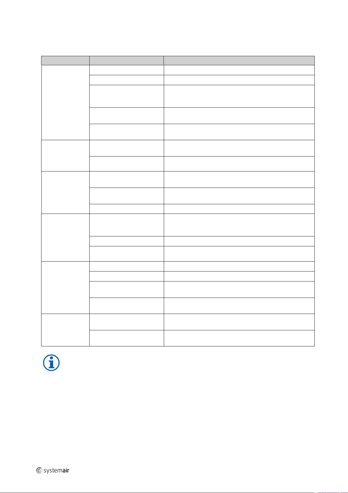
Table 14 Troubleshooting
Problem Possible causes
Fan does not run
smoothly
Air output of fan
too low
Thermal contacts/
resistors have
triggered
Fan does not
reach nominal
speed
Motor does not
rotate
Rotor imbalance Rebalancing by a specialist company
Soiling on the rotor Clean carefully, rebalance
Material decomposition on
the rotor due to aggressive
material conveyed
Rotor rotates in wrong
direction
Deformation of rotor due to
excessive temperature
Rotor rotates in wrong
direction
Intake or pressure paths are
blocked
Motor overheated
Rotor rotates in wrong
direction
Motor blocked
Electrical devices
(transformer, frequency
converter, etc.) set incorrectly
Defective motor winding
Improperly aligned drive
motor
Mechanical blockage Remove the blockage
Incorrect supply voltage Check the supply voltage, re-establish the voltage supply
Incorrect connection
Corrective actions
Contact Systemair
Change direction of rotation (swap two phases in case of a 3–
phase motor)
Ensure that the temperature does not exceed the certified
value/Install new rotor
Change direction of rotation (swap two phases in case of a 3–
phase motor)
Remove the blockage
Check the cooling impeller (if used), measure the motor
winding (if possible) / contact Systemair
Change direction of rotation (swap two phases in case of a 3–
phase motor)
Contact Systemair
Check and possibly reset setting of the devices
Contact Systemair
Contact Systemair
Disconnect from the power supply, correct the connection, see
circuit diagram
Temperature monitor has
responded
Electronics/motor
overheated
Insufficient cooling Check, if the correct fan is used for your application/improve
Ambient temperature too
high
Note:
For all other damage/defects, please contact Systemair. Defective fans must be completely replaced.
11.3 Maintenance
Draw up maintenance plan
♦ Draw up a regular maintenance plan.
♦ Document the work performed.
Allow the motor to cool down, find and resolve the cause of
the fault
cooling
Check, if the correct fan is used for your application
| 003
Page 31
Troubleshooting/maintenance/repair |
11.3.1 Variable-speed fans
Important
The fan may be destroyed due to unpermitted frequencies.
♦ Pay particular attention to damage from vibrations.
♦ After commissioning, start with shorter maintenance intervals.
♦ If no damage occurs, adjust the maintenance intervals up to the those stated in the operating
instructions.
♦ Responsibility for gradual adaptation is with the system operator.
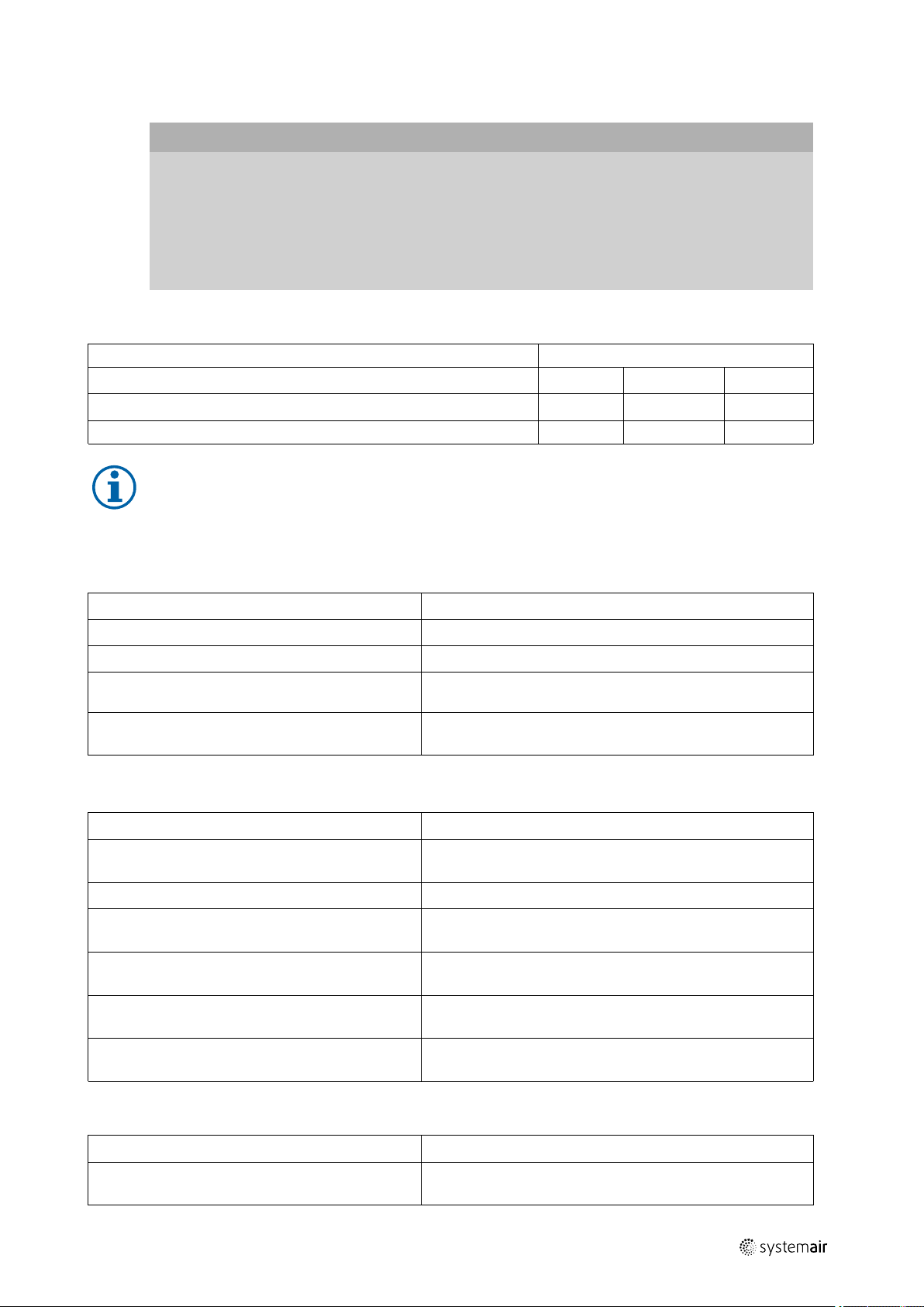
11.3.2 Maintenance intervals
Conditions Maintenance intervals
monthly biannually annually
Fan unit in rare use (less than once a month) or in emergency operation
Fan unit in use under normal conditions
X X X
-
X X
Note:
The following sections contain suggestions from Systemair on the maintenance intervals.
♦ Shorten the intervals if the fan unit is used in a particularly dirty environment.
27
11.3.3 Monthly maintenance
Check (if present)
Operational readiness of the fan unit Allow the fan to run for 2 hours
Operational readiness of the emergency system Allow the "emergency" system to run for 15 minutes
Function of the “emergency” control Test whether the “emergency” control effectively bridges all
Function of the standstill heating Switch the motor off. The standstill heating must switch on
Measures
the other controls and switches
automatically and remain switched on
11.3.4 Half-yearly maintenance
Check (if present)
Condition of the ventilation system Remove all deposits, dirt and objects, which can influence
Cooling ribs of the motor Remove all contaminations between the ribs of the motor
Fastening components (screws, nuts, cable glands,
etc.)
Blades Remove all dirt and dust deposits. Make sure that the blades
Condition of the safety devices and protective
devices
Measures
proper condition
Check the fastening components (screws, nuts, cable glands,
etc.) and tighten them if necessary.
are tight. Replace any rotors which may be damaged
Clean the safety devices and protective devices
Replace them if there are indications of damage/rust
Condition of the standstill heating Remove the motor from the electric mains
Check whether the standstill heating is activated
11.3.5 Annual maintenance
Check (if present)
Air gap between the blades and the housing of the
fan
| 003
Measures
Make sure that the air gap between the blade and the
housing is correct. See chapter Air gap.
Page 32

| Cleaning
28
Pitch angle setting and the safety of the blades Make sure that the blades are tight. If any changes are
necessary, contact Systemair
Tightening torques of the fan fittings on the base/
foundation
Fittings of the motor, fan and ancillary equipment Make sure that all fittings are present, correct, and as tight as
Condition of the anti-vibration system Check for unusual movement and screw the connection tight
Motor voltage and motor current Make sure that the measured data matches with the data on
Optional lubrication device: regreasing See manual of the motor
Make sure that the tightening torques are as tight as possible
If in doubt about the suitable tightening torques, contact
Systemair
possible
If in doubt about the suitable tightening torques, contact
Systemair.
if necessary
the name plate
Line connections of the fan accessories
Check all line connections (including grounding) for safety
and condition
11.3.6 Overhaul/further maintenance
Pay attention to the safety references and preconditions as in normal maintenance. For the following activities and
functions, contact Systemair:
• complete overhaul of motors
• replacement of bearings
• re-winding of motors
• monitoring of condition
• vibration analysis
11.3.7 After 20,000 hours of operation or 5 years of normal operation
♦ Replace the shaft sealing rings and shaft bearings.
11.3.8 After 30,000 to 40,000 hours of operation
♦ The bearings must be replaced at the end of the grease service life (about 30,000 to 40,000 h in standard
applications).
11.4 Work before switching on again
♦ Attach all the safety and protective devices tightly and securely.
♦ Remove all the devices with which you have blocked the rotor.
♦ Remove all assembly residues and foreign bodies from the area around the fan unit.
11.5 Spare parts
♦ Use original spare parts from Systemair only!
♦ When ordering spare parts, please specify the serial number of the fan. This can be found on the name plate.
12 Cleaning
12.1 Safety information
♦ Cleaning may only be carried out by adequately qualified persons, details see Table 1 Qualifications, page 2.
♦ Wear protective equipment during all work in the vicinity of the fan, details see 2.2 Personal protective equipment,
page 2.
♦ Observe the 5 rules of electrical safety, see 2.3 5 rules of electrical safety, page 2!
12.2 Preconditions
♦ The power supply has been switched off (all-pole circuit breaker).
| 003
Page 33

Deinstallation/dismantling |
♦ The rotor is at a standstill.
12.3 Procedure
Note:
Keeping the fan clean extends its service life.
♦ Install a filter monitor.
♦ Do not use steel brushes or sharp-edged objects.
♦ Do not use a high-pressure cleaner (steam jet cleaner) under any circumstances.
♦ Do not bend the fan blades when cleaning.
♦ When cleaning the rotor, pay attention to balance weights that have been positioned.
♦ Keep the airways of the fan clear and clean them if necessary with a brush.
13 Deinstallation/dismantling
Deinstall and dismantle the fan in reverse order of installation (7 Installation, page 14) and electrical connection (8 Electrical connection, page 21).
14 Disposal
29
♦ Ensure material is recycled. Observe national regulations.
♦ The device and the transport packaging are predominantly made from recyclable raw materials.
♦ Disassemble the fan into its components.
♦ Separate the parts according to:
• reusable material
• material groups to be disposed of (metal, plastics, electrical parts, etc.)
| 003
Page 34

| EU Declaration of conformity — Axial fans
30
15 EU Declaration of conformity — Axial fans
The manufacturer: Systemair GmbH
Seehöfer Straße 45
97944 Boxberg
Germany
Product designation: Axial Fans
Type designation:
Since of manufacture:
The manufacturer declares that the above mentioned products in their design and construction and the version
marketed by us complies with the Harmonization legislation listed below:
EU directives: 2006/42/EC Machinery directive
Regulations: 327/2011 only for fans above 125W, CE marked
The following standards have been considered:
Harmonized standards:
AXC; AXC (K); AXC (B); AXC (F); AXC-G; AXC (B)-G; AXC-P; AXC (B)-P; AXS;
AXC-E; AXC-EK; AXC(B)- EK; AXR; AXR (K); AXR (B); AXR (F); AXCBF; AXS; AJ;
AJ (K); AJ (B); AJ (F); AJ-TR; AR; AW
2016
2014/30/EU Directive electromagnetic compatibility
(EMC)
2011/65/EU RoHS directive
2009/125/EC ErP guidelines
fans used as components are CE
marked by other manufacturer.
DIN EN ISO 12100:2013
DIN EN 60204-1:2010
DIN EN 61000-6-1:2007
DIN EN 61000-6-2:2011
DIN EN 12101-3:2015*
Safety of machinery - General
principles for design Riskassessment
and risk reduction
Safety of machinery - Electrical
equipment of machines - Part1: General
requirements
Electromagnetic compatibility (EMC) Part 6-1: Generic standards - Immunity
for residential, commercial and lightindustrial environments
Electromagnetic compatibility (EMC) Part 6-2: Generic standards - Immunity
for industrial environments
Smoke an heat control systems, Part 3:
Specification for powered smoke and
heat exhaust ventilators
*only smoke extract fans
Boxberg, 20.04.2016
ppa. Harald Rudelgass, technical director
| 003
Page 35

16 Commissioning Report
Fan
Description:
Article no.: Manufacturing order no.:
Installer
Company: Contact person:
Company address:
Tel. no.: Email:
Operator (Place of installation)
Company: Contact person:
Company address:
Tel. no.: Email:
Commissioning Report
|
31
Type of connection
Directly to mains
0-10 V signal (EC motor)
via contactor control
Transformer
Frequency converter
Sinus filter
Shielded cables
Motor protection
Motor protection switch or motor protection relay
PTC resistor
Resistance value [Ω]:
Thermal contact
Electrical motor protection
Others:
Functional check
Impeller easily rotatable (by hand)
Rotation direction acc. to directional arrow
Yes No
□ □
□ □
□ □
□ □
□ □
□ □
□ □
Yes No
□ □
□ □
□ □
□ □
Yes No
□ □
□ □
Nominal data - Fan (name plate on fan housing)
Voltage [V]: Current [A]:
Frequency [Hz]: Power [kW]:
Fan impeller speed [rpm]:
| 003
Page 36
Commissioning Report
|
32
Measured data at commissioning
Voltage [V]: Temp. of transported air [°C]:
Current L1 [A]*:
Fan impeller speed [rpm]:
Current L2 [A]: Air volume [m3/s]:
Current L3 [A]:
*For single-phase fans, fill in line “Current L1 [A]” *Δ- Pressure between suction-side and discharge of the fan
Differential pressure [Pa]*:
If an air flow measurement is not possible, this value can be calculated using the following formula:
=
Air volume [m³/s]:
Duct cross-section [m²]
X
Flow speed [m/s]
Grille measurement acc. to VDI 2044
Yes No
Commissioning of the fan successful?
□ □
Date, installer's signature
Date, operator's signature
Please keep the completed commissioning report in a safe place. In the case of a warranty claim, this report can
be requested by Systemair GmbH. This document can also be downloaded from our online catalogue.
For technical questions, please contact the technical support division of Systemair GmbH (tel. +49 7930/9272 730).
| 003
Page 37

| 003
Page 38

Systemair GmbH
Seehöfer Str. 45
97944 Boxberg
Germany
Tel.: +49 (0)7930/9272-0
Fax: +49 (0)7930/9273-92
info@systemair.de
www.systemair.de
Axial Fans/Jet fans · Installation and Operating Instructions · · en_GB · 2017-09-26 · 003
 Loading...