

Page 1
Quick Guide
Access software 4.0-1-04 to 4.1-1-00
Document in original language | 151671 · A005
GB
Page 2

© Copyright Systemair AB
All rights reserved
E&OE
Systemair AB reserves the rights to alter their products without notice.
This also applies to products already ordered, as long as it does not affect the previously agreed specifications.
151671 | A005
Page 3

1 General.... . ...... . ...... . ...... . . ..... . . ..... . . ...... . ...... . ..1
1.1 Start-up wizard . ...... . ...... . ...... . ...... . ...... . . .2
1.2 Key board ...... . ...... . ...... . ...... . ...... . . ..... . . ..3
1.3 Symbol description . ...... . ...... . . ..... . . ...... . ...3
1.4 User levels ..... . . ..... . . ...... . ...... . ...... . ...... . ..4
2 Alarms..... . ...... . ...... . ...... . ...... . ...... . . ..... . . ..... . . ..4
2.1 Alarm list..... . ...... . . ..... . . ...... . ...... . ...... . ....4
3 Controller settings ... . . ...... . ...... . ...... . ...... . ...... . ...5
3.1 Data & Settings.... . ...... . ...... . ...... . ...... . . ....5
3.1.1 Operation overview .... . ...... . ...... . .5
3.1.2 In- and output status... . ...... . ...... . .5
3.1.3 Temperature control . . . ...... . ...... . ..6
3.1.4 Fan control .... . ...... . ...... . ...... . . ....6
3.1.5 Demand control . . . ..... . . ...... . ...... . .6
3.1.6 Fire/Smoke.... . . ..... . . ..... . . ..... . . ....6
3.1.7 Humidity control . . . ...... . ...... . ...... . 7
3.2 Flow chart . ...... . ...... . ...... . ...... . . ..... . . ...... .7
3.3 Language ...... . . ..... . . ..... . . ...... . ...... . ...... . ..7
3.4 Time Settings ..... . . ..... . . ...... . ...... . ...... . .....8
3.5 Configuration ...... . ...... . ...... . ...... . ...... . .....9
4 Advanced HMI (Human Machine Interface)
Settings ...... . . ..... . . ..... . . ...... . ...... . ...... . ...... . .... 10
5 No communication . . ..... . . ..... . . ...... . ...... . ...... . ... 11
Contents
151671 | A005
Page 4

Page 5
General |
1 General
NaviPad is Systemair's user interface with a 7” capacitive touch screen. The user interface provides operation information about the connected air handling units and allows you to control all functions. You navigate by pressing the
touchscreen, to activate a function, change setting or by reading values in real time.
After 5 min inactivity the screen activate sleep mode, you return to the screen you left by pressing the touchscreen.
After additional 10 min. inactivity you return to the system overview dashboard (figure 3) and have to log in again.
Editable text and values are shown in blue and differs depending on user level.
Since the user interface of the air handling unit consists of a web server with web pages it is possible to use a computer
to browse the user interface. Identify the IP address of the air handling unit with NaviPad, see Example 4 and then write
it in the address field of an internet browser.
Important
• The air handling unit and the NaviPad as well as any computer has to be connected on a local network
with the same IP subnet.
• Chrome browser for computer is supported to navigate the web pages of the air handling unit.
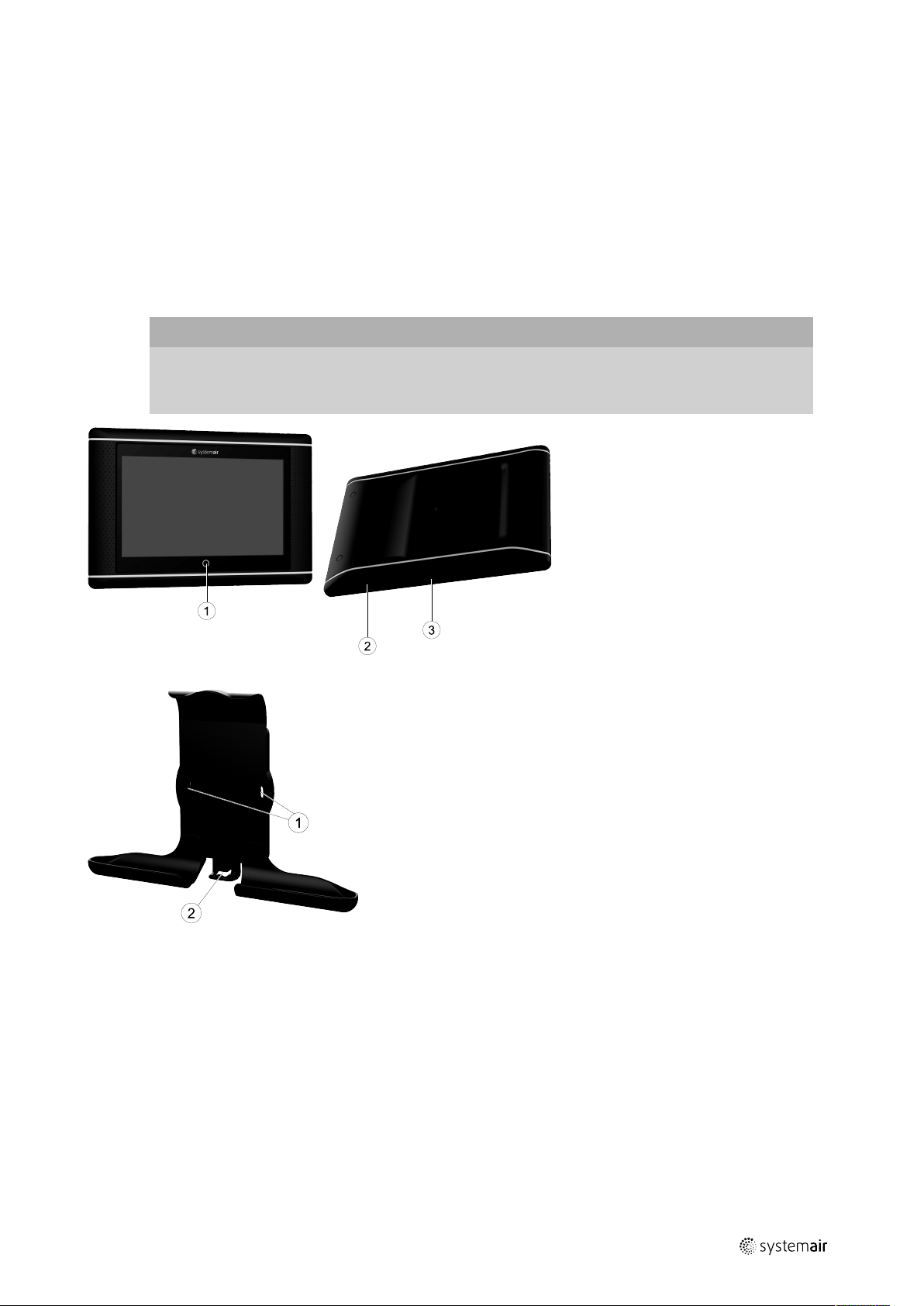
1
Fig. 1 (1) Home button, (2) USB connection, reboot button, (3) power supply and communication
Fig. 2 Holder for NaviPad, (1) fixing points, (2) cable hook
Attach holder to air handling unit with enclosed screws (wall mounting is also possible, use fastenings suitable to the walls structure).
151671 | A005
Page 6

| General
2
1.1 Start-up wizard
At the first start up of NaviPad you need to calibrate the screen by pressing lightly on the cross marks.
Then you will be requested to fill in following information:
• Language
• Time & Date
Available air handling units will be shown in the device list. Choose the air handling unit you want to pair with your NaviPad. Use the controller’s serial number in the air handling unit to be sure to pair the correct air handling unit with
NaviPad.
If the start-up wizard is cancelled it will start again during next power up of the NaviPad, this will continue until start-up
wizard is successfully finished.
Version: PR1.2 (1.1.0.128) and later
Start-up wizard
started
↓
Scan for air handling
units
↓
Show air handling
units selection menu
← 0
Numbers of air
handling units
detected
≥1
↓
Select air handling unit
↓
User input
After the start-up wizard is completed the system overview dashboard is shown. Press on the picture of the air handling unit to access.
Home > Available devices
Select language
↓
Set Time & Date
↓
System overview
dashboard
13 Dec 11:33
Unit name
Normal operation
Figure 3: System dashboard
151671 | A005
Page 7

Unit name 13 Dec 11:33
-2°C +2°C0
General |
3
Running mode
Normal speed
Extended run
120
min
Figure 4: The home page shows an overview of the air handling unit operation status.
Outdoor
31.3 °C 16.1 °C
Setpoint adjustment
Note:
You can always return to system overview dashboard by pressing the home button, figure 1, (1).
1.2 Key board
Supply
When a name, value or password need to be changed/written a key board will appear at the bottom of the
touchscreen.
1.3 Symbol description
Home (home page)
Data and settings
Shows operating information and settings
Flow diagram
A schematic overview of the air handling unit and its components
Language
Change language
Time and date
Weekly schedule
Configuration
Alarm and functions configurations, I/O allocation settings
Alarm symbol, indicates if there are active alarms. One press on the symbol will direct you to the alarm
list.
151671 | A005
Page 8

| Alarms
4
1.4 User levels
End user
When logged out
Read /write — Home page (Figure 1)
Possible actions in end user mode are to stop the air handling unit for
maintenance (e.g. filter exchange), change the time for extended run and
change the temperature setpoint.
Flow diagram and active alarms in alarm list are visible.
Operator mode — log in
with 1111
Logged in
Service mode — log in
with 0612
Logged in
Read and write privileges (except Configuration).
Acknowledge/block/unblock alarms and view the alarm history.
Full read and write privileges.
2 Alarms
A LED-light in the home button, figure 1, (1) indicate the status of the air handling unit.
• Fixed green — Status ok (no active alarms).
• Flashing red — Active/returned alarms in one or several air handling units.
• Fixed red — Acknowledged/blocked alarms in one or several air handling units, alarms not reset.
Different alarm levels
Class A alarm
Needs to be acknowledged
Class B alarm
Needs to be acknowledged
Class C alarm
Returns when the cause of the alarm disappear
2.1 Alarm list
Data & Settings > Alarm list
Acknowledge all
Name:
Filter guard 1
Show all alarms
Alarm history
Alarm status:
• Alarmed
• Acknowledged
• Blocked
• Returned
Accessible when pressing the alarm symbol.
13 Dec 11:33
Level:
No
Status:
Alarmed
>
>
Enter the current alarm and choose action; acknowledge, block or unblock.
151671 | A005
Page 9

Controller settings |
3 Controller settings
Menus and functions may differ depending on actual configuration and/or application version running in the air handling
unit.
3.1 Data & Settings
5
Data & Settings
Operation overview
In-/Output status
Temperature control
Fan control
Demand control
Fire/Smoke
Alarm list
3.1.1 Operation overview
Value of active signals
I/O signals and operation mode.
• Temperature
• Air flow/pressure
• CO2
• RH
• Heating
• Exchanger
• Cooler
• Recirculation
13 Dec 11:33
>
>
>
>
>
>
>
3.1.2 In- and output status
I/O status
Total overview of:
• Sensors
• I/O
• Fan control
• Temperature sequencing
• Running mode
All can be controlled in manual mode.
• Manual setting of temperature sensor
• Locking of fans at adjustment
• Manually I/O testing of external functions
• Raw values
151671 | A005
Page 10

| Controller settings
6
3.1.3 Temperature control
Settings for temperature.
• Limit values
• Setpoint for current control type (Example 1)
• Min/max limitation
• Outdoor temperature values
Example 1: Setpoint for current control type
Data & Settings > Temperature control > Supply air controller
Supply air temperature
Setpoint adjustment
Setpoint adjustment low speed
Setpoint adjustment high speed
Setpoint Supply air
Example show temperature control type set to supply air. To change the setpoint, press on the current value and
change to desired setting in the following pop-up menu. Confirm with ok. (Editable text and values are shown in blue
on NaviPad.)
13 Dec 11:33
10.4 °C
0 °C
0 °C
0 °C
18 °C
3.1.4 Fan control
Settings for fan control.
• Setpoint for different fan speed
• Fan compensation e.g. outdoor compensated fan curves
• Start delay of fans, shut of dampers etc.
• SFP menu
• External fans
3.1.5 Demand control
Settings for:
• CO2
• Recirculation
• Support control
• Free cooling
3.1.6 Fire/Smoke
Settings for:
• Fire dampers
• Smoke detector status
• Fire damper test
151671 | A005
Page 11

3.1.7 Humidity control
199 Pa
198 Pa
18 000 m³/h
18 000 m³/h
100 %
54 Pa
34 Pa
22,1 °C
22,1 °C
-6,8 °C
-12,2 °C
71 %
74 %
16,7 °C
21,8 °C
19,9 °C
25 % RH71 % RH
32 % RH
84 %
h
Open
Open
0 %
OFF
42 %
ON
Setpoints and settings for dehumidification and humidification
3.2 Flow chart
Controller settings |
7
Flow diagram
13 Dec 11:33
Dynamic flow chart of current configured air handling unit. Active sensors and components are visible
with values shown in real time. When pressing on values or items marked in blue you will be forwarded
to related settings and/or overview page.
3.3 Language
Settings of language.
• To synchronize NaviPad with all connected air handling units, go to system dashboard by pressing the
• Using
151671 | A005
home button figure 1, (1). Press
in selected air handling units homepage via NaviPad or computer will only change language
in the selected air handling unit.
and , choose language.
Page 12

| Controller settings
8
3.4 Time Settings
In this menu date and time can be changed as well as other system settings.
Settings for:
• Date and time
• Schedule for operating time (Example 2 & 3)
• Schedule for holiday
• Schedule for extra time groups
Each day has up to two individual running periods, set desired start and stop time.
For holidays, set the dates in Time settings > Schedule > Holiday calendar and the time in
Time settings > Schedule > Fan Low Speed/Fan Normal Speed/High Speed.
Example 2: Schedule for normal fan speed
Time settings > Schedule > Fan Normal Speed
Start
Monday
(12–hour clock system)
Monday
(24–hour clock system)
In above example, the air handling unit starts at a normal fan speed at 5:00 AM (05:00) and stops at 6:00 PM (18:00).
The second running period is deactivated.
Example 3: Schedule for low fan speed
Time settings > Schedule > Fan Low Speed
Monday
(12–hour clock system)
Monday
(24–hour clock system)
5:00 AM 6:00 PM 12:00 AM 12:00 AM
05:00 18:00 00:00 00:00
Start
6:00 PM 24:00 AM 12:00 AM 5:00 AM
18:00 24:00 00:00 05:00
Stop
Stop
13 Dec 11:33
Start
13 Dec 11:33
Start
Stop
Stop
In above example, the air handling unit starts at a low fan speed at 6:00 AM (18:00) and stops at 24:00 AM (24:00).
The second running period on low fan speed is between 12:00 AM (00:00) and 5:00 AM (05:00).
151671 | A005
Page 13

Controller settings |
3.5 Configuration
• System settings
• Configuration wizard (Example 4)
• Function configuration (Example 5)
• I/O allocation settings
• Alarm configuration (Example 6)
• PID controllers
The configuration wizard is a menu that simplify the procedure to Activate and Configure common accessories and
functions and Allocate it’s in- and outputs. The wizard makes necessary configurations automatically and guide the user
through limited options.
Example 4: Configuration wizard
9
Configuration > Configuration wizard
Set up pressure control
Set up cooler
Set up changeover
Exit to configuration menu > Complete configuration wizard >
If the configuration wizard does not cover the desired accessory or function it can still be configured via the configuration menu.
Example 5: Function configuration
Configuration > Functions > Function activation
Fan compensation curves
Support control
CO2 Control
To activate a function go to Function activation. Choose function to activate and set Yes in the following pop-up
menu. Values for the activated function are now visible and can be adjusted in Data Settings.
13 Dec 11:33
>
>
>
13 Dec 11:33
Yes
No
No
If required, allocate in- and outputs in I/O allocation settings.
151671 | A005
Page 14

|
10
Advanced HMI (Human Machine Interface) Settings
Example 6: Alarm configuration
Configuration > Alarms
Filter alarm supply air
Filter alarm extract air
Alarm low air flow
Freeze protection guard
Defrosting guard exchanger
Fire alarm
Smoke alarm
Configuration > ... > Filter alarm supply air
Action: No action
Level: Class B
Delay:
300 s
No: 53
Name:
Filter alarm supply air
Original text: Filter alarm supply air
13 Dec 11:33
Limit X1: 0 m
3
/h
Limit X2: 2000 m
13 Dec 11:33
3
/h
53
54
55
56
57
58
59
Limit Y1: 10 Pa
Limit Y2: 150 Pa
4 Advanced HMI (Human Machine Interface) Settings
Return to system overview dashboard by pressing on the home button, figure 1, (1). Go to and choose
Advanced HMI settings. Login required — 1111
NaviPad settings
Home
Unit name
Normal operation
Language
Time & Date setting
Advanced HMI
settings
Restart NaviPad
• Available devices (air handling units) (Example 7)
• Change Password
• Ethernet setting: IP address can be configured to either obtain an IP address from a DHCP server (dynamic) or set
manually as a static IP addres
1
• Restore NaviPad Factory Settings (Example 8)
• Software Update
1
For further support setting a static IP address, see “Access Manual Communication”
13 Dec 11:33
151671 | A005
Page 15

Example 7: Available devices (air handling units)
No communication
|
11
Home > Advanced HMI settings > Available decives
192.168.41.38
Select device
Serial number:
012345678910
Serial number:
058345678919
The air handling unit will appear, press the button to select the air handling unit to pair it with the NaviPad. If there are
several air handling units at the same IP subnet, a list of available air handling units will be presented.
The IP address of NaviPad itself is presented above the Select device header
Example 8: Restore NaviPad factory settings
You will be requested to confirm your action.
All settings including password will be reset and Start-Up wizard will run again.
IP Address:
192.168.41.116
IP Address:
192.168.41.49
13 Dec 11:33
Name:
Unit name
Name:
Unit name
5 No communication
Home > Available devices
13 Dec 11:33
Unit name
No Communication
If the above symbol are shown the communication to the selected air handling unit is lost. One reason could be that the
IP number has changed. Go back to available devices (air handling units), figur 4, and first deactivate all the air handling
units and then activate them again.
151671 | A005
Page 16

Systemair Sverige AB
Industrivägen 3
SE-739 30 Skinnskatteberg, Sweden
Phone +46 222 440 00
Fax +46 222 440 99
www.systemair.com
Quick Guide · · 151671 · en_GB · 2019-12-16 · A005
 Loading...