

Page 1

Quick configuration guide
Access software 4.0-1-04 to 4.1-1-00
Document in original language | 157618 · A004
GB
Page 2

© Copyright Systemair AB
All rights reserved
E&OE
Systemair AB reserves the rights to alter their products without notice.
This also applies to products already ordered, as long as it does not affect the previously agreed specifications.
157618 | A004
Page 3

1 About this document..... . . .. . .. . .. . .. . .. . .. . .. . .. . . .. . .. . .. 1
2 How to set up a function ...... . . .. .. . .. . . .. . .. . .. . .. . .. . . .. 1
2.1 Login . . .. . .. . .. . .. . .. . .. . . .. . .. . .. . .. . .. . .. . .. . .. . . .. . .. 1
2.2 Activation.... . . .. . .. . .. . .. . .. . . .. . .. .. . . .. . .. . .. . .. . .. 1
2.3 Configuration ... . .. . .. . . .. . .. . .. . .. . .. . .. . .. . .. . . .. . .1
2.4 Allocation .. .. . .. . .. . .. . .. . . .. .. . . .. . .. . .. . .. . .. . .. . . .. 1
2.5 Operation settings .... . . .. . .. . .. . .. . .. . . .. . .. . .. . .. . 1
3 How to use the configuration wizard... . . .. . .. . .. . .. . .. . 2
3.1 Set up an accessory or function with
the configuration wizard .. . . .. . .. . .. . . .. . .. . .. . .. . 2
4 Save commissioning settings . . .. . .. . .. . .. . .. . .. . . .. . .. . .. 4
5 Quick configuration guides .. . . .. . .. . .. . .. . .. . . .. . .. . .. . .. . 4
5.1 Editable naming . . . .. . .. . .. . .. . .. . .. . . .. . .. . .. . .. . .. . 4
5.2 Alarm configuration . . .. . .. . .. . .. . .. . .. . .. . .. . . .. . .. 6
5.3 Fan control type (Pressure)..... . . .. . .. . .. . .. . .. . .6
5.4 Temperature control type (Room) ..... . .. . . .. . .8
5.5 Extended operation . . .. . .. . .. . .. . .. . .. . .. . . .. . .. . 10
5.6 Fan compensation ... . .. . .. . .. . . .. .. . . .. . .. . .. . .. . 12
5.7 CO2 control (Fan start/stop) ... . . .. . .. . . .. . .. .. 14
5.8 Fire/Smoke function (Fire). . .. . .. . .. . .. . .. . . .. .. 16
5.9 Free cooling .. . . .. .. . .. . . .. . .. . .. . .. . .. . . .. .. . .. . . .. 19
5.10 External cooler (DX) ...... . .. . .. . . .. . .. . .. . .. . .. . .21
5.11 External heater (Water) . . .. . .. . . .. . .. . .. . .. . .. . . 25
5.12 Changeover .. . . .. .. . . .. . .. . .. . .. . .. . .. . . .. .. . . .. . .. 29
5.13 External stop .... . . .. . .. . .. . .. . .. . . .. . .. . .. . .. . .. . .. 30
5.14 Support control ..... . . .. .. . . .. . .. . .. . .. . .. . .. . . .. .. 31
Contents
157618 | A004
Page 4

Page 5

About this document |
1 About this document
This document describes how to setup functions in your Access controller and contains quick configuration guides for
the most common functions. All available functionality is described in detail in the “Access 4x configuration manual”
available on the online catalogue or Systemair Configurator for products using the Access control platform.
2 How to set up a function
To set up a function in the access controller you need to be logged in as Service to access the configuration menu. After
login you follow a 4-step procedure to successfully setup the function. Please note that not all functions require all four
steps. The general procedure for setting up a function is described below. Function specific configuration guides are
found later in the document.
2.1 Login
Log in with service mode using password 0612.
Overview:
Service
0612
Login
1
Step by step:
1.
2.
3.
4.
Open the log in window
Select service from drop down list
Type in password 0612
Press Login.
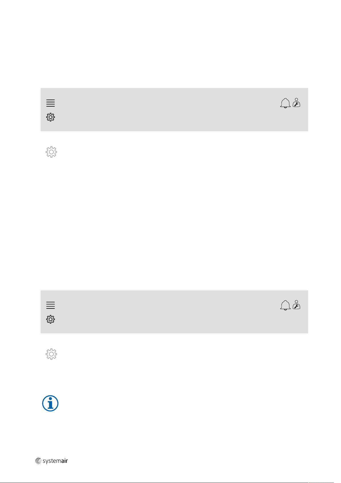
2.2 Activation
Configuration > Functions > Function activation
Activate a function in a list of available functions (e.g. heater).
2.3 Configuration
Configuration > Functions
Select the function's configuration (e.g. if heater is water, electric etc.).
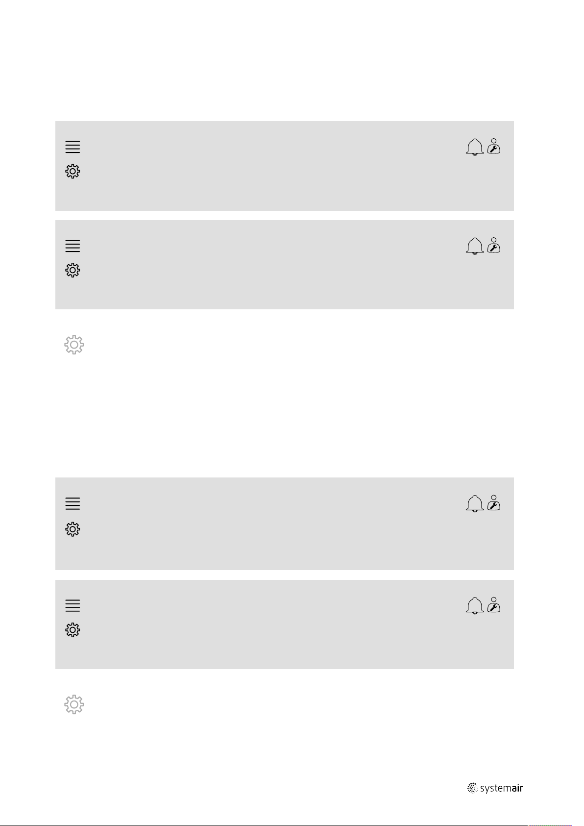
2.4 Allocation
Configuration > I/O allocation settings
Select the I/O (in-/output) placement of the connected signals and sensors. Configure I/O settings (sensor measuring
range, polarity, edit name of sensor/signal etc.).
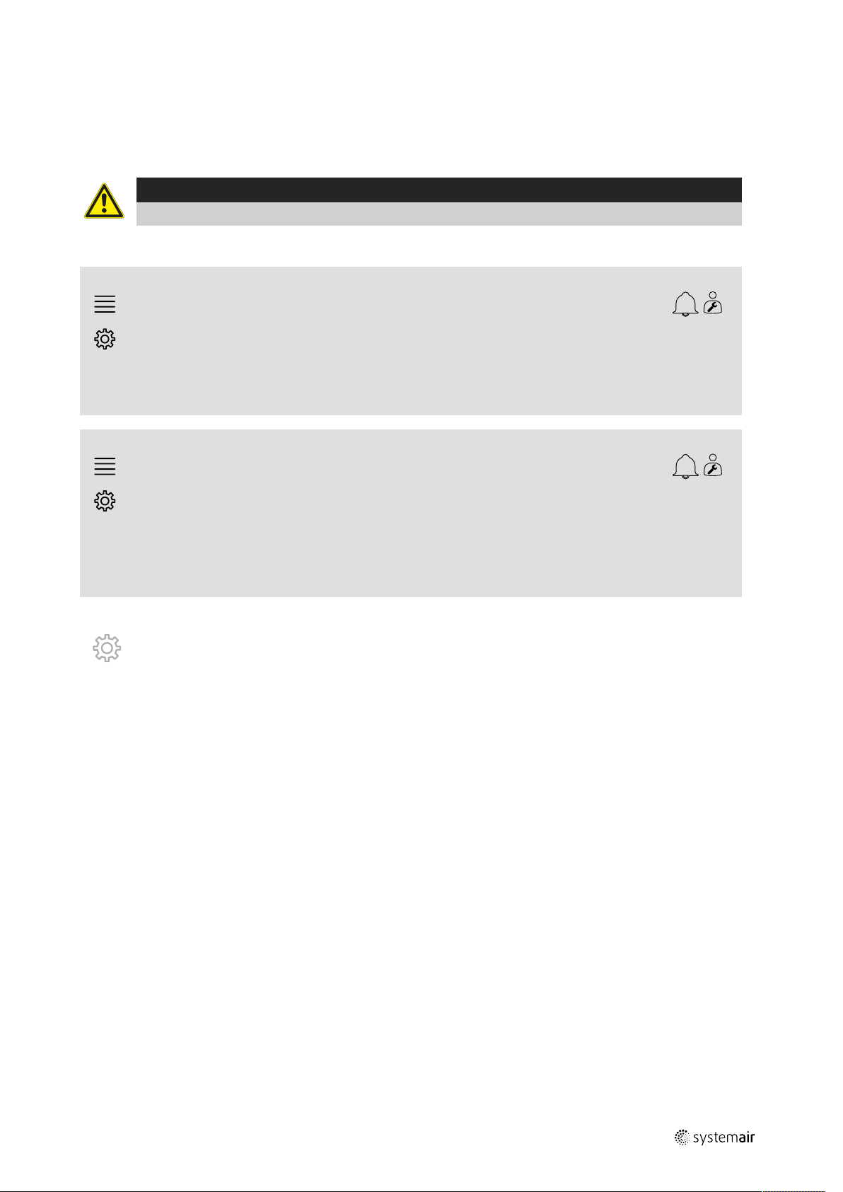
Caution
Do no use the same in- or output for several functions.
2.5 Operation settings
Data & Settings
Setup how the function will work (e.g. setpoints, limits etc.)
157618 | A004
Page 6

| How to use the configuration wizard
2
3 How to use the configuration wizard
The configuration wizard is a menu that simplify the procedure to Activate and Configure common accessories and
functions and Allocate it’s in- and outputs. The wizard makes necessary configurations automatically and guide the user
through limited options.
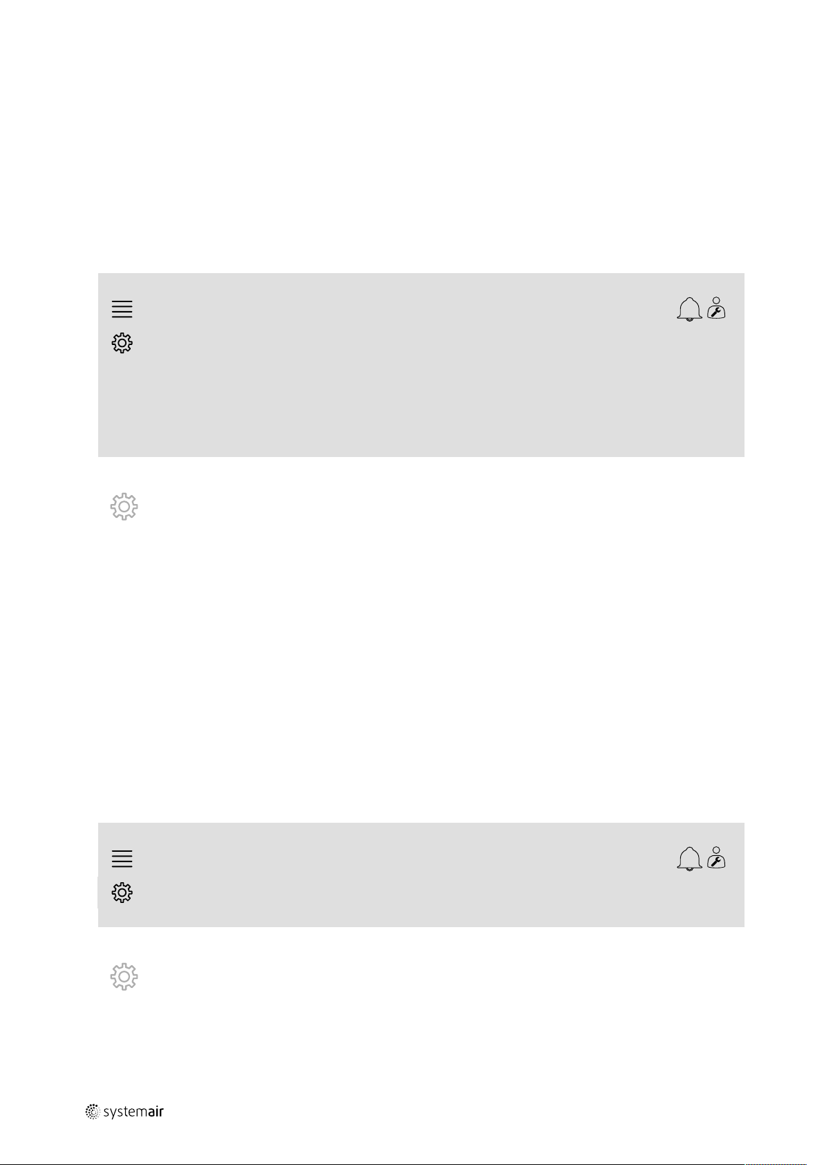
Access the configuration wizard via
in the navigation bar or via the configuration menu.
Note:
The wizard’s availability and content depend on the air handling unit’s model and controller software
version.
If the configuration wizard does not cover the desired accessory or function it can still be configured via the
configuration menu.
3.1 Set up an accessory or function with the configuration wizard
3.1.1 Activation
Configuration > Configuration wizard
Select the type of accessory or function you wish to set up. E.g. if you have installed a water coil for cooling as accessory, select Set up cooler.
Configuration > Configuration wizard
Set up pressure control
Set up cooler
Set up changeover
Exit to configuration menu > Complete configuration wizard >
11 Dec 10:33
>
>
>
3.1.2 Configuration
Configuration > Configuration wizard < Set up “function”
Specify the details of the accessory or function you wish to set up. E.g. If the cooler you wish to set up is of type Water
and that the circulation pump is with an alarm feedback signal.
Configuration > Configuration wizard < Set up
cooler
Type of cooler
Type of feedback
Pump control
Pump running mode
11 Dec 10:33
Water
Alarm
Yes
Auto
Confirm configuration and
continue >
Note:
The amount of steps between different setups may vary. E.g. when configuring pressure control the wizard
makes the necessary configuration steps automatically and only require confirmation of in- and output
allocation and settings.
157618 | A004
Page 7

How to use the configuration wizard |
3.1.3 Allocation
Configuration > Configuration wizard > Set up “function” > In-/Outputs
Confirm the in-/output allocation of the connected signals and sensors. Configure in-/output settings (sensor measuring
range, polarity, edit name of sensor/signal etc.) as necessary. Complete the setup by pressing Confirm In-/Outputs
and complete setup.
3
Configuration > ... > Set cooler > In-/Outputs
Analog outputs
Cooling (SEQ-C)
Digital outputs
Cooling pump (SEQ-C) Normally open
Digital Inputs
Feedback cooling (SEQ-C) Normally open
Range output
0–10V Controller AO2
Contact function Device Position
Contact function Device Position
Confirm In-/Outputs and complete setup >
11 Dec 10:33
Device Position
Controller DO3
Controller DI5
3.1.4 Completing the configuration wizard
A completed setup is listed as Configured in the configuration wizard menu. To make changes to an already configured function, rerun the wizard or use the configuration menus described in chapter 5.
Configuration > Configuration wizard
Set up pressure control
Set up cooler Configured
Set up changeover
Exit to configuration menu > Complete configuration wizard >
11 Dec 10:33
>
>
>
Select Complete configuration wizard once the desired setups have been completed. The configuration wizard
is still accessible from the configuration menu.
3.1.5 Operation settings
Note that functions configured via the wizard still require adaptation of its operation settings. These settings are found
in the functions submenu of Data & Settings as described in chapter 5.
157618 | A004
Page 8
Save commissioning settings
|
4
4 Save commissioning settings
When the installation is complete and all functions are tested it is recommended to save a local backup of the current
configuration in the control unit.
Select Yes on Save commissioning settings in the Configuration > System settings > Save and restore
settings menu.
Overview:
Configuration > System settings > Save and restore
settings
Save commissioning settings
Step by step:
1.
2. Select System settings
3. Select Save and restore settings
4. Select Yes on Save commissioning settings.
Select Configuration from the navigation icons
11 Dec 10:33
Yes
5 Quick configuration guides
5.1 Editable naming
The access control unit interface allow for editable naming of the air handling unit, I/O’s (in-/outputs), heating/cooling
sequences and alarms. Edit name in the control unit is done in the Configuration submenus by editing the menu
row Name. Edited names persist if a new language is selected but the menu row Original name will always be translated and can be used for reference.
5.1.1 Air handling unit naming
The air handling unit’s name is shown in the top-right of the “Home” screen. Edit the name by changing the menu row
Unit name found in the Configuration > System settings > Communications devices menu.
Overview:
Configuration > System settings > Communication devices
Unit name
Step by step:
1.
2. Select System settings
3. Select Communication devices
4. Edit the name of the air handling unit by selecting Unit name.
Select Configuration from the navigation icons
11 Dec 10:33
Systemair controller
Note:
Default Unit name is either Systemair controller or the unit model name. e.g. Topvex TR03 HW CAV.
157618 | A004
Page 9
Quick configuration guides |
5.1.2 I/O naming
Change the name of an I/O (in-/outputs), for example a temperature sensor, by selecting the desired I/O function in
the Configuration > I/O allocation settings sub menus and changing the menu row Name.
Overview:
5
Configuration > I/O allocation settings > Analog
inputs
Analog inputs
Supply air temperature
Configuration >... > Analog inputs > Supply air
temperature
Name
Original name Supply air temperature
Step by step:
1.
2. Select I/O allocation settings
3. Select the submenu related to the I/O to rename (e.g Analog inputs if temperature sensor)
4. Select the I/O function of which to rename (e.g Supply air temperature)
5. Edit the name of the I/O (in-/outputs) by selecting Name.
Select Configuration from the navigation icons
11 Dec 10:33
Device Position
Controller
11 Dec 10:33
Supply air temperature
AI1
5.1.3 Sequence naming
Change the name of a heating/cooling sequence by selecting the desired sequence in the Configuration > Functions > Function activation >Heating/Cooling sequence setup menu and changing the menu row Name.
Configuration > ... > ... > Heating/Cooling sequence
setup
Position
SEQ-H
Configuration >... > Heating/Cooling sequence setup >
Cooling 2
Name
Original name Cooling 2
Step by step:
1.
2. Select Functions
3. Select Function activation
4. Select Heating/Cooling sequence setup
Select Configuration from the navigation icons
Heating Cooling
Off
Start
Heating
3 0 % 0 %
Start
Cooling
Name
Cooling 2
11 Dec 10:33
>
11 Dec 10:33
Cooling 2
157618 | A004
Page 10
| Quick configuration guides
6
5. Select the sequence to rename (e.g Cooling 2)
6. Edit the name of the sequence by selecting Name.
5.1.4 Alarm naming
How to edit alarm names is described in chapter 5.2.
5.2 Alarm configuration
Configure any alarm available in the controller in the Configuration > Alarms menu.
Overview:
Configuration > ... > Extra alarm 1
Action: No action
Level: Disabled
Delay:
No:
Name:
Step by step:
1.
2. Select Alarms
3. Select the desired alarm after scrolling through the list of all alarms and identifying the alarm via either name or alarm
4. Select the action the unit will take when the alarm is active (e.g Normal stop) as Action
5. Select the desired Alarm class or disable the alarm (e.g Class B) as Level
6. Adjust the time before the alarm activates as Delay
7. Adjust the name of the alarm as Name.
Select Configuration from the navigation icons
number
0 s
68
Extra alarm 1
11 Dec 10:33
5.3 Fan control type (Pressure)
5.3.1 Activation
Activate pressure control.
Select Fan control type as Pressure in the Configuration > Functions > Function activation menu.
Overview:
Configuration > Functions > Function activation
Fan control type
Step by step:
1.
2. Select Functions
3. Select Function activation
4. Select Pressure as Fan control type.
Select Configuration from the navigation icons
11 Dec 10:33
Pressure
157618 | A004
Page 11
Quick configuration guides |
5.3.2 Allocation
Setup differential pressure sensors.
Select I/O (in-/output) placement for where the differential pressure sensors are connected. Set the sensors’ signal and
corresponding measuring range in the Configuration > I/O allocation settings > Analog inputs menu.
Caution
Do not use the same in- or output for several functions.
Overview:
7
Configuration > I/O allocation settings > Analog
inputs
Analog inputs
Pressure supply air
Pressure extract air Controller
Configuration > ... > Analog inputs > Pressure supply
air
Min volt input (Vmin)
Max volt input (Vmax)
Sensor value at Vmin 0.0
Sensor value at Vmax
Step by step:
1.
2. Select I/O allocation settings
3. Select Analog inputs
4. Select the input connected to the sensor (e.g. UI2) as position for Pressure supply air
5. Select the input connected to the sensor (e.g UI1) as position for Pressure extract air
6. Select Pressure supply air
7. Set Sensor at Vmin the same as the start point of the sensor’s selected measuring range
8. Set Sensor at Vmax the same as the end point of the sensor’s selected measuring range
9. Set Min volt input (Vmin) and Max volt input (Vmax) to values corresponding to the sensor’s signal type (e.
10.Go back to Analog inputs (use the navigation path Configuration > I/O allocation settings > Analog
11.Select Pressure extract air and repeat steps 7 through 9.
Select Configuration from the navigation icons
g. 0…10V, 2…10V etc.)
inputs)
11 Dec 10:33
Device Position
Controller
11 Dec 10:33
UI2
UI1
0.0 V
10.0 V
500.0
157618 | A004
Page 12

| Quick configuration guides
8
5.3.3 Operation settings
Adjust the fan pressure set points in the Data & Settings > Fan Control > Fan setpoints menu.
Overview:
Data & Settings > Fan control > Fan setpoints
Setpoint low speed supply air fan 100 Pa
Setpoint low speed extract air fan
Setpoint normal speed supply air fan 200 Pa
Setpoint normal speed extract air fan
Setpoint high speed supply air fan 200 Pa
Setpoint high speed extract air fan
Step by step:
1.
2. Select Fan control
3. Select Fan setpoints
4. Select and adjust setpoints for the available fan speed levels.
Select Data & Settings from the navigation icons
11 Dec 10:33
100 Pa
200 Pa
200 Pa
5.4 Temperature control type (Room)
5.4.1 Activation
Activate room temperature control.
Select Cascade room temp control as temperature control type in the Configuration > Functions > Func-
tion activation menu.
Overview:
Configuration > Functions > Function activation
Temperature control type
Step by step:
1.
2. Select Functions
3. Select Function activation
4. Select Room cascade as Temperature control type.
Select Configuration from the navigation icons
11 Dec 10:33
Room cascade
157618 | A004
Page 13

Quick configuration guides |
5.4.2 Configuration
Configure the number of connected room temperature sensors in the Configuration > Functions > Temperature control menu.
Overview:
9
Configuration > Functions > Temperature control
Room temperature sensor
Step by step:
1.
2. Select Functions
3. Select Temperature control
4. Select number of connected Room temperature sensors
Select Configuration from the navigation icons
11 Dec 10:33
1
5.4.3 Allocation
Select I/O (in-/output) placement for where the room temperature sensors are connected to the controller in the Configuration > I/O allocation settings > Analog inputs menu.
Overview:
Configuration > I/O allocation settings > Analog
inputs
Analog inputs
11 Dec 10:33
Device Position
Room temperature 1
Room temperature 2
Room temperature 3
Room temperature 4
Step by step:
1.
2. Select I/O allocation settings
3. Select Analog inputs
4. Select the input connected to the sensor (e.g. UI1) as position for Room temperature 1/2/3/4
5. Repeat step 4 for any remaining room temperature sensors.
Select Configuration from the navigation icons
Controller Select I/O
Controller Select I/O
Controller Select I/O
Controller Select I/O
157618 | A004
Page 14

| Quick configuration guides
10
5.4.4 Operation settings
Data & Settings > Temp Control > Supply air
controller
Min limit supply air
Max limit supply air
Step by step:
1.
2. Select Temperature control
3. Select Room controller
4. Adjust Setpoint room to the desired temperature setpoint
5. Go back to Temperature control (use the navigation path Data & Settings > Temperature control)
6. Select Supply air controller
7. Set Min limit supply air to the lowest permitted supply air temperature
8. Set Max limit supply air to the highest permitted supply air temperature.
Select Data & Settings from the navigation icons
11 Dec 10:33
14.0 °C
30.0 °C
5.5 Extended operation
5.5.1 Activation
Select Yes on Extended operation in the Configuration > Functions > Function activation menu.
Overview:
Configuration > Functions > Function activation
Extended operation
Step by step:
1.
2. Select Functions
3. Select Function activation
4. Select Yes on Extended operation.
Select Configuration from the navigation icons
11 Dec 10:33
Yes
5.5.2 Configuration
Select which of the configured fan speeds to enable extended operation for in the Configuration > Functions >
Extended operation menu.
Overview:
Configuration > Functions > Extended operation
11 Dec 10:33
Extended operation low speed
Extended operation normal speed
Extended operation high speed
Step by step:
No
Yes
Yes
157618 | A004
Page 15

Quick configuration guides |
1. Select Configuration from the navigation icons
2. Select Functions
3. Select Extended operation
4. Select Yes for desired extended operation fan speeds
5.5.3 Allocation
Select I/O (in-/output) placement for the extended operation speeds in the Configuration >I/O allocation settings > Digital inputs menu
Overview:
11
Configuration > I/O allocation settings > Digital
inputs
Digital inputs
Extended operation low speed
Extended operation normal speed
Extended operation high speed
Step by step:
1.
2. Select I/O allocation settings
3. Select Digital inputs
4. Select the input of the extended operation (e.g. DI4) as position for Extended operation low speed, Extended
5. Repeat step 4 for any remaining extended operation speeds.
Select Configuration from the navigation icons
operation normal speed, Extended operation high speed
11 Dec 10:33
Device Position
Controller Select I/O
Controller
Controller Select I/O
DI4
5.5.4 Operation settings
Adjust extended operation time to the desired stop delay in the Time settings menu.
Overview:
Time settings
Extended operation stop delay 0 min
Step by step:
1.
2. Set the desired stop delay as Extended operation stop delay
Select Time settings from the navigation icons
157618 | A004
11 Dec 10:33
Page 16

| Quick configuration guides
12
5.6 Fan compensation
5.6.1 Activation
Select Yes for Fan Compensation in the Configuration > Functions > Function activation menu.
Overview:
Configuration > Functions > Function activation
Fan compensation curves
Step by step:
1.
2. Select Functions
3. Select Function activation
4. Set Yes on Fan compensation curves
Select Configuration from the navigation icons
11 Dec 10:33
Yes
5.6.2 Configuration
Select and configure a fan compensation curve in the Configuration > Functions > Fan compensation curves
menu.
Overview:
Configuration > Functions > Fan compensation curves
Fan compensation curve 1
11 Dec 10:33
>
Fan compensation curve 2
Fan compensation curve 3
Configuration > ... > Fan compensation curve 1
Fan level All levels
Mode Inactive
Fan
Sensor Select I/O
11 Dec 10:33
Supply air fan + Exhaust air fan
>
>
157618 | A004
Page 17

Step by step:
Quick configuration guides |
13
1.
2. Select Functions
3. Select Fan compensation curve 1/2/3
4. Select which fan level(s) the compensation curve should apply to as Fan level
5. Select when the compensation curve is active as Mode
6. Select which fan the compensation curve applies to as Fan
7. Select which of the available sensors to use for compensation.
Select Configuration from the navigation icons
5.6.3 Operation settings
Set up fan setpoint compensation values and sensor input values for the curve points in the Data & Settings > Fan
control > Fan compensation curves menu.
Overview:
Data & Settings > Fan control > Fan compensation curves
Fan compensation curve 1
Fan compensation curve 2
Fan compensation curve 3
11 Dec 10:33
>
>
>
Data & Settings > ... > Fan compensation curves > Fan
compensation curve 2
Compensation curve
Lowest sensor value
Middle sensor value
Highest sensor value
Step by step:
1.
2. Select Fan control
3. Select Fan compensation curves
4. Select Fan compensation curve 1/2/3
5. Set up Lowest sensor value
6. Set up Middle sensor value
7. Set up Highest sensor value
Select Data & Settings from the navigation icons
a. Set the lowest sensor value for compensation as Sensor value
b. Set the desired fan setpoint compensation at that sensor value as Compensation
a. Set a middle sensor value for compensation as Sensor value
b. Set the desired fan setpoint compensation at that sensor value as Compensation
a. Set the highest sensor value for compensation as Sensor value
b. Set the desired fan setpoint compensation at that sensor value as Compensation
Sensor
value
15.0 °C
20.0 °C
25.0 °C
11 Dec
10:33
Compensation
0.0 Pa
0.0 Pa
0.0 Pa
157618 | A004
Page 18

| Quick configuration guides
14
5.7 CO2 control (Fan start/stop)
5.7.1 Activation
Activate the Fan start/stop function for CO2 control from the list of available functions in the Configuration > Functions > Function activation menu.
Overview:
Configuration > Functions > Function activation
CO2 Control
Step by step:
1.
2. Select Functions
3. Select Function activation
4. Press CO2 Control
5. Select Fan start/stop function from drop down list.
Select Configuration from the navigation icons
11 Dec 10:33
Fan start/stop
function
5.7.2 Configuration
Select which fan speeds the unit should start/run on when CO2 control Fan start/Stop function is active in the
Configuration > Functions > CO2 Control menu.
Overview:
Configuration > Functions > CO2 control
11 Dec 10:33
Setpoint supply air fan when CO2 control Normal speed
Setpoint exhaust air fan when CO2 control Normal speed
Step by step:
1.
2. Select Functions
3. Select CO2 control
4. Set the desired supply air fan speed for Fan start/stop function as Setpoint supply air fan when CO2
5. Set the desired extract air fan speed for Fan start/stop function as Setpoint extract air when CO2
Select Configuration from the navigation icons
control
control.
157618 | A004
Page 19

Quick configuration guides |
5.7.3 Allocation
Select I/O (in-output) placement for where the CO2 sensor is connected to the controller in the Configuration > I/
O allocation settings > Analog inputs menu.
Overview:
15
Configuration > I/O allocation settings > Analog
inputs
Analog inputs
CO2 room/extract air Controller
Configuration > ... > Analog inputs > CO2 room/extract air
Min volt input (Vmin)
Man volt input (Vmax)
Sensor value at Vmin 0.0
Sensor value at Vmax
Step by step:
1.
2. Select I/O allocation settings
3. Select Analog inputs
4. Select the input connected to the sensor (e.g. UI3) as position for CO2 room/extract air
5. Select CO2 room/extract air
6. Set Sensor value at Vmin the same as the start point of the sensor’s selected measuring range
7. Set Sensor value at Vmax the same as the end point of the sensor’s selected measuring range
8. Set Min volt input (Vmin) and Max volt input (Vmax) to values corresponding to the sensor’s signal type (e.
Select Configuration from the navigation icons
g. 0…10 V, 2…10 V etc.)
11 Dec 10:33
Device Position
UI3
11 Dec 10:33
0.0 V
10.0 V
2000.0
157618 | A004
Page 20

| Quick configuration guides
16
5.7.4 Operating settings
Adjust CO2 limits for the Fan start/stop function and adjust the minimum run time for CO2 control in the Data & Settings > Demand control > CO2 menu.
Overview:
Data & Settings > Demand control > CO2
Start limit fan start/stop
Stop hysteresis fan start/stop
Min time for CO2 control 20 min
Step by step:
11 Dec 10:33
800 ppm
160 ppm
Note:
Setpoint CO2 not active for this configuration. Setpoint CO2 is only used by CO2 function Mixing damper.
1.
2. Select Demand control
3. Select CO2
4. Set Start limit fan start/stop to the desired CO2 level to start the fan start/stop function
5. Set Stop hysteresis fan start/stop to the desired amount that the CO2 level needs to decrease to end the
Select Data & Settings from the navigation icons
fan start/stop function.
5.8 Fire/Smoke function (Fire)
5.8.1 Activation
Activate the Fire function by selecting the Fire option for Fire/Smoke in the list of available functions in the Configuration > Functions > Function activation menu.
Overview:
Configuration > Functions > Function activation
Fire/Smoke Fire
Step by step:
1.
2. Select Functions
3. Select Function activation
4. Select Fire as Fire/Smoke
Select Configuration from the navigation icons
11 Dec 10:33
157618 | A004
Page 21

Quick configuration guides |
5.8.2 Configuration
Configure the operation of the air handling unit, outdoor/exhaust air dampers, the fan setpoints and fire damper function when Fire alarm in the Configuration > Functions > Fire/Smoke > Fire function submenus.
Overview:
17
Configuration > ... > Fire/Smoke > Fire function
Operation mode when fire alarm
Supply air fan setpoint type when fire alarm Manual output
Manual output
Extract air fan setpoint type when fire alarm Manual output
Manual output
Outdoor air damper function when fire alarm
Exhaust air damper function when fire alarm
Configuration > ... > Fire function > Fire damper
Mode Not active
Test No test
Step by step:
11 Dec 10:33
Continuous run
75%
75%
Normal function (follow the
fan)
Normal function (follow the
fan)
11 Dec 10:33
1.
2. Select Functions
3. Select Fire/Smoke
4. Select Fire function
5. Select desired air handling unit’s operation when fire alarm as Mode
6. Select desired fan setpoint type as Supply air fan setpoint type when fire alarm
7. Select desired fan setpoint type as Extract air fan setpoint type when fire alarm
8. If either Manual setpoint or Manual output was selected set the desired value in the corresponding menu row
9. Select the operation of the outdoor/exhaust air damper when fire alarm as Outdoor/Exhaust air damper when
10.Select Fire damper
11.Select the normal position of the fire dampers or if fire damper function should not be used as Mode
12.Select if and how the fire dampers shall be tested as Test.
Select Configuration from the navigation icons
now visible
fire alarm
157618 | A004
Page 22

| Quick configuration guides
18
5.8.3 Allocation
Select I/O (in-/output) placement of where fire alarm activation input, fire damper output and position feedback input
are connected to the controller in the Configuration > I/O allocation settings submenus Digital inputs
and Digital outputs.
Overview:
Configuration > I/O allocation settings > Digital
inputs
Digital inputs
Fire alarm Controller DI5
Feedback fire damper
Configuration > I/O allocation settings > Digital
outputs
Digital outputs
Fire damper
Step by step:
1.
2. Select I/O allocation settings
3. Select Digital inputs
4. Select the input connected to the fire alarm contact/sensor (e.g. DI5) as position for Fire alarm
Select Configuration from the navigation icons
11 Dec 10:33
Device Position
Controller
11 Dec 10:33
Device Position
Controller DO5
DI6
Note:
Step 5-8: Only applicable if fire dampers are configured.
5. Select the input connected to the fire damper position switches (e.g. DI6) as position for Feedback fire damper
6. Go back to I/O allocation settings (use the navigation path Configuration > I/O allocation
settings)
7. Select Digital outputs
8. Select the output connected to the fire damper (e.g. DO5) as position for Fire damper.
157618 | A004
Page 23

5.8.4 Operation settings
Set up the Fire damper test settings in the Data & Settings > Fire/Smoke menu.
Note:
Only applicable if fire damper test is configured.
Overview:
Quick configuration guides |
19
Data & Settings > Fire/Smoke
Run time fire damper 90 s
Test interval fire damper 7 days
Test hour fire damper 15
Step by step:
1.
2. Select Fire/Smoke
3. Set max allowed fire damper run time as Run time fire damper
4. Set day interval between fire damper tests as Test interval fire damper
5. Select hour (1-24) for start of fire damper test as Test hour fire damper, e.g 15 means the fire damper test will
Select Data & Settings from the navigation icons
initiate at 3 pm (15:00) on test day.
11 Dec 10:33
5.9 Free cooling
5.9.1 Activation
Select Yes as Free Cooling from the list of available functions in the Configuration > Functions > Function
activation menu.
Overview:
Configuration > Functions > Function activation
Free cooling
Step by step:
1.
2. Select Functions
3. Select Function activation
4. Select Yes as Free cooling
Select Configuration from the navigation icons
11 Dec 10:33
Yes
157618 | A004
Page 24

| Quick configuration guides
20
5.9.2 Operation settings
Set up all operation parameters for the free cooling function in the Data & Settings > Demand control > Free
cooling menu.
Overview:
Data & Settings > Demand control > Free cooling
Running when day outdoor temperature >
Stop when night outdoor temperature >
Stop when night outdoor temperature <
Stop when room temperature <
Free cooling start hour
Free cooling stop hour 7
Time to block heat output after free cooling 60 min
Fan-kick temperature check 180 s
Fan-kick interval time 60 min
Step by step:
1.
2. Select Demand control
3. Select Free cooling
4. Set day outdoor temperature min. limit to allow start of free cooling as Running when day outdoor
5. Set outdoor temperature interval during night where free cooling is allowed as Stop when night outdoor
6. Set Room/Extract air temperature min. limit to stop free cooling
7. Set a time interval for when free cooling is allowed to run (0-24) as Free cooling start/stop hour, e.g. 0-7
8. Set the desired time to block heating output from the controller after free cooling
9. Set the desired fan run time for checking the outdoor temperature with an intake temperature sensor
10.Set the time delay between outdoor temperature checks with an intake temperature sensor.
Select Data & Settings from the navigation icons
temperature>
temperature >/<
means free cooling will run between 12 am (12:00) and 7 am (07:00) if allowed by the temperature limits)
11 Dec 10:33
22 °C
18 °C
10 °C
18 °C
0
157618 | A004
Page 25

Quick configuration guides |
5.10 External cooler (DX)
5.10.1 Activation
Select and activate an unused cooling sequence (C, H or J) in the Configuration > Functions > Function activation > Heating/Cooling sequence setup menu.
Overview:
21
Configuration > ... > ... > Heating/Cooling sequence
setup
Position
SEQ-C
SEQ-H
SEQ-J
Heating Cooling
Off
Off
Off Off
2 0 % 0 %
3 0 % 0 %
Start
Heating
0 % 0 %
Cooling
Start
Name
Cooling
Cooling 2
External
heating/cooling
capacity
11 Dec 10:33
Note:
Off = Sequence not activated. Sequence with lower number activates before sequence with higher number.
In software version 4.0–1–05 the term “Off” is replaced with “No”.
Step by step:
1.
2. Select Functions
3. Select Function activation
4. Select Heating/Cooling sequence setup
5. 5. Assign the activation order for the cooling sequence by selecting number (1-10) in column Cooling for
Select Configuration from the navigation icons
SEQ-C, -H or -J
>
>
>
157618 | A004
Page 26

| Quick configuration guides
22
5.10.2 Configuration
Configure what type of cooler is connected in the Configuration > Functions > Function activation > Heating/Cooling sequence setup > Cooling menu.
Overview:
Configuration >. .. > Heating/Cooling sequence setup >
Cooling
Type of sequence Cooling
Type of cooler
Type of feedback
Digital start output
Step by step:
1.
2. Select Functions
3. Select Heating/Cooling sequence setup
4. Select Cooling (SEQ-C)
5. Set Type of sequence to Cooling
6. Select the type of cooler (e.g. DX)
7. Select the type of feedback from the cooler as Type of feedback (e.g. Alarm or Run indication)
8. Select Yes as Digital start output if the external cooler requires a digital start signal.
Select Configuration from the navigation icons
11 Dec 10:33
5.10.3 Allocation
DX
Alarm
Yes
Select I/O (in-output) placement of where the cooler control signal output, digital start output and feedback input are
connected to the controller in the Configuration > I/O allocation settings submenus Digital inputs,
Analog outputs and Digital outputs.
Overview:
Configuration > I/O allocation settings > Digital
inputs
Digital inputs
Feedback cooling (SEQ-C)
Configuration > I/O allocation settings > Analog
outputs
Analog outputs
Cooling (SEQ-C)
11 Dec 10:33
Device Position
Controller UI4
11 Dec 10:33
Device Position
Controller AO4
157618 | A004
Page 27

Quick configuration guides |
23
Configuration >... > Analog outputs > Cooling (SEQ-C)
Range output
Configuration > I/O allocation settings > Digital
outputs
Digital outputs
Cooling start (SEQ-C)
Step by step:
1.
2. Select I/O allocation settings
3. Select Digital inputs
4. Select the input connected to the cooler’s feedback contact (e.g. UI4) as position for Feedback cooling (SEQ-C)
5. Go back to I/O allocation settings (use the navigation path Configuration > I/O allocation
6. Select Analog outputs
7. Select the analog output connected to the cooler control signal (e.g. AO4) as position for Cooling (SEQ-C)
8. Select Cooling (SEQ-C)
9. Adjust Range output to fit with the signal range of the external cooler (e.g. 2-10 V)
10.Go back to I/O allocation settings (use the navigation path Configuration > I/O allocation
11.Select Digital outputs
12.Select the digital output connected to the cooler (e.g. DO4) as position for Cooling start (SEQ-C).
Select Configuration from the navigation icons
settings)
settings)
11 Dec 10:33
0–10 V
11 Dec 10:33
Device Position
Controller DO4
157618 | A004
Page 28

| Quick configuration guides
24
5.10.4 Operation settings
Adjust the start/stop point for the digital output: Cooling start (SEQ-C) in the Data & Settings > Temperature
control > Cooling menu.
Overview:
Data & Settings > Temperature control > Cooling
Digital start output start point 10 %
Digital start output stop point 1 %
Data & Settings > Temperature control > Supply air
controller
Min limit supply air
Max limit supply air
Reduction of min limit supply air if active DX-cooling
Step by step:
1.
2. Select Temperature control
3. Select Cooling
4. Set the desired output % to activate the digital output as Digital start output start point
5. Set the desired output % to deactivate the digital output as Digital start output stop point
6. Go back to Temperature control (use the navigation path Data & Settings > Temperature control)
7. Select Supply air controller
8. Adjust the min. allowed supply air temperature when DX-Cooling is active as Reduction of min limit supply
Select Data & Settings from the navigation icons
air if active DX-cooling.
11 Dec 10:33
11 Dec 10:33
14 °C
30 °C
5 °C
157618 | A004
Page 29

Quick configuration guides |
5.11 External heater (Water)
5.11.1 Activation
Select and activate an unused heating sequence (A, G or J) in the Configuration > Functions > Function activation > Heating/Cooling sequence setup menu.
Overview:
25
Configuration > ... > ... > Heating/Cooling sequence
setup
Position
SEQ-A
SEQ-G
SEQ-J
Step by step:
1.
2. Select Functions
3. Select Function activation
4. Select Heating/Cooling sequence setup
5. 5. Assign the activation order for the heating sequence by selecting number (1-10) in column Heating for
Select Configuration from the navigation icons
SEQ-A, -G or -J
Heating Cooling
2
3
Off Off
Off
Off
Start
Heating
0 % 0 %
0 % 0 %
0 % 0 %
Start
Cooling
Name
Heating
Heating 2
External
heating/cooling
capacity
11 Dec 10:33
Note:
Off = Sequence not activated. Sequence with lower number activates before sequence with higher number.
In software version 4.0–1–05 the term “Off” is replaced with “No”.
>
>
>
157618 | A004
Page 30

| Quick configuration guides
26
5.11.2 Configuration
Configure what type of heater that is connected (e.g. water) and additional functions such as freeze protection and
pump control in the Configuration > Functions > Function activation > Heating/Cooling sequence
setup > Heating menu.
Overview:
Configuration > ... > Heating/Cooling sequence setup >
Heating
Type of sequence Heating
Type of heater
Type of freeze protection
Freeze protection sensor
Pump control
Pump running mode
Type of feedback
Step by step:
1.
2. Select Functions
3. Select Function activation
4. Select Heating/Cooling sequence setup
5. Select Heating (SEQ-A)
6. Select Water as Type of heater
7. Select Temperature sensor as Type of freeze protection
8. Select an unused sensor (e.g. 1) as Freeze protection temperature sensor
9. Select Yes as Pump control
10.Select the desired type of pump control (e.g. Auto) as Pump running mode
11.Select the desired type of pump feedback (e.g. Alarm) as Type of feedback.
Select Configuration from the navigation icons
11 Dec 10:33
Water
Temperature sensor
Freeze protection
temperature 1
Yes
Auto
Alarm
157618 | A004
Page 31

Quick configuration guides |
5.11.3 Allocation
Select I/O (in-output) placement of where the heater control signal output, pump start output and pump feedback input
are connected to the controller in the Configuration > I/O allocation settings submenus Digital inputs,
Analog outputs and Digital outputs.
Overview:
27
Configuration > I/O allocation settings > Digital
inputs
Digital inputs
Feedback heating (SEQ-A)
Configuration > I/O allocation settings > Analog
outputs
Analog outputs
Heating (SEQ-A)
Configuration > ... > Analog outputs > Heating (SEQ-A)
Range output
Configuration > I/O allocation settings > Digital
outputs
11 Dec 10:33
Device Position
Controller UI4
11 Dec 10:33
Device Position
Controller AO4
11 Dec 10:33
0-10 V
11 Dec 10:33
Digital outputs
Heating pump (SEQ-A)
Step by step:
1.
2. Select I/O allocation settings
3. Select Digital inputs
4. Select the input connected to the circulation pump’s feedback contact (e.g. UI4) as position for Feedback heating
5. Go back to I/O allocation settings (use the navigation path Configuration > I/O allocation
6. Select Analog outputs
7. Select the analog output connected to the valve actuator control signal (e.g. AO4) as position for Heating (SEQ-A)
8. Select Heating (SEQ-A)
9. Adjust Range output to fit with the signal range of the valve actuator (e.g. 0-10 V)
10.Go back to I/O allocation settings (use the navigation path Configuration > I/O allocation
11.Select Digital outputs
12.Select the digital output connected to the circulation pump (e.g. DO1) as postion for Heating pump (SEQ-A).
Select Configuration from the navigation icons
(SEQ-A)
settings)
settings)
Device Position
Controller DO1
157618 | A004
Page 32

| Quick configuration guides
28
5.11.4 Operation settings
Adjust the settings for pump control and freeze protection in the Data & Settings > Temperature control >
Heating menu
Overview:
Data & Settings > Temperature control > Heating
Pump stop delay
Pump-kick hour 15 h
Pump running when outdoor temperature <
Hysteresis to allow pump stop
Freeze protection 1
Data & Settings > ... > Heating > Freeze protection 1
Alarm limit running mode
P-band running mode
Setpoint stand-by mode
Step by step:
1.
2. Select Temperature control
3. Select Heating
4. Set the desired time for Pump stop delay
5. Set the desired hour to test the pump as Pump-kick hour (e.g. 15 means the pump will be tested at 3 pm (15:00)
6. Adjust the outdoor temperature to start the pump as Pump running when outdoor temperature <
7. Adjust the increase in the outdoor temperature to stop the pump as Hysteresis to allow pump stop
8. Select Freeze protection 1
9. Adjust the freeze protection alarm limit as Alarm limitation running mode
10.Adjust the temperature range of where freeze protection starts overriding the actuator as P-band running mode
11.Adjust the freeze protection function’s setpoint for when the unit is stopped as Setpoint standby mode.
Select Data & Settings from the navigation icons
each day)
(e.g. if Alarm limit running mode = 7 °C and P-band running mode = 5 °C the freeze protection will start overriding the actuator when the freeze protection temperature reaches 12 °C)
11 Dec 10:33
5 min
10 °C
1 °C
>
11 Dec 10:33
7 °C
5 °C
20 °C
157618 | A004
Page 33

Quick configuration guides |
5.12 Changeover
5.12.1 Configuration
Select one heating sequence and one cooling sequence out of the configured sequences to use with the changeover
function in the Configuration > Functions > Function activation > Heating/Cooling sequence setup >
Changeover settings menu.
Overview:
29
Configuration > ... > Heating/Cooling sequence setup >
Changeover settings
Changeover 1
Changeover sequence for heating Heating
Changeover sequence for cooling Cooling
Step by step:
1.
2. Select Functions
3. Select Function activation
4. Select Heating/Cooling sequence setup
5. Select Changeover settings
6. Select which sequence to control the changeover function when heating as Changeover sequence for heating
7. Select which sequence to control the changeover function when cooling as Changeover sequence for cooling.
Select Configuration from the navigation icons
11 Dec 10:33
5.12.2 Allocation
Select I/O (in-output) placement of where the changeover output and feedback input are connected to the controller in
the Configuration > I/O allocation settings submenus Digital inputs, Analog outputs and Digital
outputs.
Overview:
Configuration > I/O allocation settings > Digital
inputs
Digital inputs
Cooling/(Heating) changeover 1
Configuration > I/O allocation settings > Analog
outputs
Analog outputs
Changeover 1
11 Dec 10:33
Device Position
Controller
11 Dec 10:33
Device Position
Controller AO4
DI4
157618 | A004
Page 34

| Quick configuration guides
30
Configuration > ... > Analog outputs > Changeover 1
Range output
Step by step:
1.
2. Select I/O allocation settings
3. Select Digital inputs
4. Select the input connected to the heating/cooling feedback (e.g. DI4) as position for Cooling/(Heating)
5. Go back to I/O allocation settings (use the navigation path Configuration > I/O allocation
6. Select Analog outputs
7. Select the analog output connected to the control signal (e.g. AO4) as position for Changeover 1
8. Select Changeover 1
9. Adjust Range output to the desired voltage range (e.g. 0-10 V).
Select Configuration from the navigation icons
changeover 1
settings)
11 Dec 10:33
0-10 V
5.13 External stop
5.13.1 Activation
Set External stop to Yes in the list of available functions in the Configuration > Functions > Function activation menu.
Overview:
Configuration > Functions > Function activation
External stop
Step by step:
1.
2. Select Functions
3. Select Function activation
4. Select Yes as External stop.
Select Configuration from the navigation icons
11 Dec 10:33
Yes
157618 | A004
Page 35

Quick configuration guides |
5.13.2 Allocation
Select the I/O (in-output) placement of where the external stop switch is connected to the controller in the Configuration > I/O allocation settings > Digital inputs menu.
Overview:
31
Configuration > I/O allocation settings > Digital
inputs
Digital inputs
External stop
Step by step:
1.
2. Select I/O allocation settings
3. Select Digital inputs
4. Select the input connected to the external stop switch (e.g. DI6) as position for External stop.
Select Configuration from the navigation icons
11 Dec 10:33
Device Position
Controller
DI6
5.14 Support control
5.14.1 Activation
Set Support control to Yes in the from the list of available function in the Configuration > Functions > Function activation menu.
Overview:
Configuration > Functions > Function activation
Support control
Step by step:
1.
2. Select Functions
3. Select Function activation
4. Select Yes as Support control
Select Configuration from the navigation icons
11 Dec 10:33
Yes
157618 | A004
Page 36

| Quick configuration guides
32
5.14.2 Operating settings
Adjust the start/stop limits for support heating/cooling and the min run time for the support control function in the
Data & Settings > Demand control > Support control menu.
Overview:
Data & Settings > Demand control > Support Control
Min time for support control 20 min
Start heating room temperature
Stop heating room temperature
Start cooling room temperature
Stop cooling room temperature
Step by step:
1.
2. Select Demand control
3. Select Support control
4. Adjust the minimum run time in support control as Min time for support control
5. Adjust the start and stop temperatures for support heating as Start heating room temperature, Stop heating
6. Adjust the start and stop temperatures for support cooling as Start cooling room temperature, Stop cooling
Select Data & Settings from the navigation icons
room temperature
room temperature
11 Dec 10:33
15 °C
21 °C
30 °C
28 °C
157618 | A004
Page 37

157618 | A004
Page 38

Systemair Sverige AB
Industrivägen 3
SE-739 30 Skinnskatteberg, Sweden
Phone +46 222 440 00
Fax +46 222 440 99
www.systemair.com
Quick configuration guide · · 157618 · en_GB · 2019-12-13 · A004
 Loading...