

Page 1
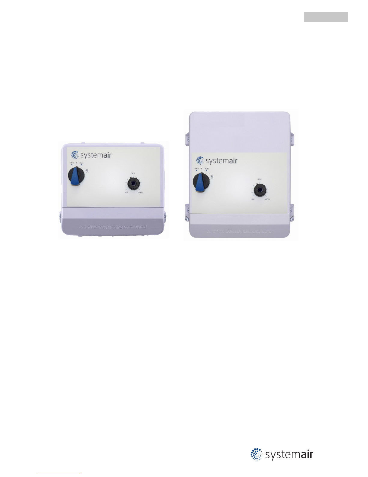
RETP6 / RETP10
Multipurpose controller for variable voltage 1 ~ fans
Operating Instructions
Software version: B1061AA from version 1.01
L-BAL-E082-GB 1237 Index 002 Part.-No. 00163339-GB
english
Page 2

Content
1 General notes . . . . . . . . . . . . . . . . . . . . . . . . . . . . . . . . . . . . . . . . . . . . . . . . . . . . . . . . . . . . . 4
1.1 Structure of the operating instructions . . . . . . . . . . . . . . . . . . . . . . . . . . . . . . . . . . . . . 4
1.2 Target group . . . . . . . . . . . . . . . . . . . . . . . . . . . . . . . . . . . . . . . . . . . . . . . . . . . . . . . . . 4
1.3 Exclusion of liability . . . . . . . . . . . . . . . . . . . . . . . . . . . . . . . . . . . . . . . . . . . . . . . . . . . 4
1.4 Copyright . . . . . . . . . . . . . . . . . . . . . . . . . . . . . . . . . . . . . . . . . . . . . . . . . . . . . . . . . . . 4
2 Safety instructions . . . . . . . . . . . . . . . . . . . . . . . . . . . . . . . . . . . . . . . . . . . . . . . . . . . . . . . . . 4
2.1 Intended use . . . . . . . . . . . . . . . . . . . . . . . . . . . . . . . . . . . . . . . . . . . . . . . . . . . . . . . . 4
2.2 Explanations of symbols . . . . . . . . . . . . . . . . . . . . . . . . . . . . . . . . . . . . . . . . . . . . . . . . 4
2.3 Product safety . . . . . . . . . . . . . . . . . . . . . . . . . . . . . . . . . . . . . . . . . . . . . . . . . . . . . . . 5
2.4 Requirements placed on the personnel / due diligence . . . . . . . . . . . . . . . . . . . . . . . . 5
2.5 Start-up and during operation . . . . . . . . . . . . . . . . . . . . . . . . . . . . . . . . . . . . . . . . . . . . 5
2.6 Work on the device . . . . . . . . . . . . . . . . . . . . . . . . . . . . . . . . . . . . . . . . . . . . . . . . . . . 5
2.7 Modifications / interventions in the device . . . . . . . . . . . . . . . . . . . . . . . . . . . . . . . . . . 6
2.8 Operator’s obligation of diligence . . . . . . . . . . . . . . . . . . . . . . . . . . . . . . . . . . . . . . . . . 6
2.9 Employment of external personnel . . . . . . . . . . . . . . . . . . . . . . . . . . . . . . . . . . . . . . . . 6
3 Product overview . . . . . . . . . . . . . . . . . . . . . . . . . . . . . . . . . . . . . . . . . . . . . . . . . . . . . . . . . . 6
3.1 Operational area . . . . . . . . . . . . . . . . . . . . . . . . . . . . . . . . . . . . . . . . . . . . . . . . . . . . . . 6
3.2 Maintenance . . . . . . . . . . . . . . . . . . . . . . . . . . . . . . . . . . . . . . . . . . . . . . . . . . . . . . . . . 6
3.3 Transport . . . . . . . . . . . . . . . . . . . . . . . . . . . . . . . . . . . . . . . . . . . . . . . . . . . . . . . . . . . 6
3.4 Storage . . . . . . . . . . . . . . . . . . . . . . . . . . . . . . . . . . . . . . . . . . . . . . . . . . . . . . . . . . . . . 7
3.5 Disposal / recycling . . . . . . . . . . . . . . . . . . . . . . . . . . . . . . . . . . . . . . . . . . . . . . . . . . . 7
4 Mounting . . . . . . . . . . . . . . . . . . . . . . . . . . . . . . . . . . . . . . . . . . . . . . . . . . . . . . . . . . . . . . . . . 7
4.1 General notes . . . . . . . . . . . . . . . . . . . . . . . . . . . . . . . . . . . . . . . . . . . . . . . . . . . . . . . . 7
4.2 Minimum space requirement . . . . . . . . . . . . . . . . . . . . . . . . . . . . . . . . . . . . . . . . . . . . 7
4.3 Outdoor installation . . . . . . . . . . . . . . . . . . . . . . . . . . . . . . . . . . . . . . . . . . . . . . . . . . . . 7
4.4 Installation location for agriculture . . . . . . . . . . . . . . . . . . . . . . . . . . . . . . . . . . . . . . . . 8
4.5 Temperature influences during commissioning . . . . . . . . . . . . . . . . . . . . . . . . . . . . . . . 8
5 Electrical installation . . . . . . . . . . . . . . . . . . . . . . . . . . . . . . . . . . . . . . . . . . . . . . . . . . . . . . . 8
5.1 Safety precautions . . . . . . . . . . . . . . . . . . . . . . . . . . . . . . . . . . . . . . . . . . . . . . . . . . . . 8
5.2 EMC-compatible installation . . . . . . . . . . . . . . . . . . . . . . . . . . . . . . . . . . . . . . . . . . . . . 8
5.2.1 Motor cable . . . . . . . . . . . . . . . . . . . . . . . . . . . . . . . . . . . . . . . . . . . . . . . . . . . 8
5.2.2 Signal cable . . . . . . . . . . . . . . . . . . . . . . . . . . . . . . . . . . . . . . . . . . . . . . . . . . . 8
5.2.3 Harmonics current for devices ≤ 16 A . . . . . . . . . . . . . . . . . . . . . . . . . . . . . . . . 8
5.3 Mains connection . . . . . . . . . . . . . . . . . . . . . . . . . . . . . . . . . . . . . . . . . . . . . . . . . . . . . 9
5.4 Motor connection . . . . . . . . . . . . . . . . . . . . . . . . . . . . . . . . . . . . . . . . . . . . . . . . . . . . . 9
5.4.1 Running noise . . . . . . . . . . . . . . . . . . . . . . . . . . . . . . . . . . . . . . . . . . . . . . . . . 9
5.5 Motor protection . . . . . . . . . . . . . . . . . . . . . . . . . . . . . . . . . . . . . . . . . . . . . . . . . . . . . . 9
5.6 Signal or sensor connection (E1 = Analog In 1) . . . . . . . . . . . . . . . . . . . . . . . . . . . . . . 9
5.7 Output voltage 0 - 10 V (A1 = Analog Out 1) . . . . . . . . . . . . . . . . . . . . . . . . . . . . . . . . 10
5.8 Voltage supply for external devices (+24V, GND) . . . . . . . . . . . . . . . . . . . . . . . . . . . . . 10
5.9 Digital input (Digital In 1 = D1) . . . . . . . . . . . . . . . . . . . . . . . . . . . . . . . . . . . . . . . . . . . 10
5.9.1 Enable, device ON / OFF . . . . . . . . . . . . . . . . . . . . . . . . . . . . . . . . . . . . . . . . . 11
5.9.2 Reverse action of control function (only for P-Controller / PI-Controller) . . . . . . . . . . 11
5.10 Relay output (K1) . . . . . . . . . . . . . . . . . . . . . . . . . . . . . . . . . . . . . . . . . . . . . . . . . . . . . 11
5.11 Potential at control voltage connections . . . . . . . . . . . . . . . . . . . . . . . . . . . . . . . . . . . . 11
6 Operating and display elements . . . . . . . . . . . . . . . . . . . . . . . . . . . . . . . . . . . . . . . . . . . . . . 12
6.1 Main switch and potentiometer with integrated light signal . . . . . . . . . . . . . . . . . . . . . . 12
6.2 Internal Setting . . . . . . . . . . . . . . . . . . . . . . . . . . . . . . . . . . . . . . . . . . . . . . . . . . . . . . . 13
Operating Instructions RETP6 / RETP10
L-BAL-E082-GB 1237 Index 002 Part.-No. 00163339-GB
2/31
Page 3

7 Base setup . . . . . . . . . . . . . . . . . . . . . . . . . . . . . . . . . . . . . . . . . . . . . . . . . . . . . . . . . . . . . . . 14
7.1 Programming of the desired function (Speed controller / P-Controller, PI-Controller) . . 14
7.2 Select operation mode . . . . . . . . . . . . . . . . . . . . . . . . . . . . . . . . . . . . . . . . . . . . . . . . . 14
7.3 Function of dipswitches for operation as Speed controller
1.01 (DIP 1 = |OFF|) . . . . 15
7.4 Function of dipswitches for operation as P-Controller, PI-Controller,
2.01 , 3.01 , 4.01
(DIP 1 = |ON|) . . . . . . . . . . . . . . . . . . . . . . . . . . . . . . . . . . . . . . . . . . . . . . . . . . . . . . . 15
7.5 Minimum speed cut off DIP 5 . . . . . . . . . . . . . . . . . . . . . . . . . . . . . . . . . . . . . . . . . . . . 16
7.5.1 For mode Speed controller
1.01 . . . . . . . . . . . . . . . . . . . . . . . . . . . . . . . . . . . . 16
7.5.2 For operation as P-Controller, PI-Controller
2.01 , 3.01 , 4.01 . . . . . . . . . . . . . . . . 16
7.6 Hardstart function DIP 6 . . . . . . . . . . . . . . . . . . . . . . . . . . . . . . . . . . . . . . . . . . . . . . . . 16
8 Start-up . . . . . . . . . . . . . . . . . . . . . . . . . . . . . . . . . . . . . . . . . . . . . . . . . . . . . . . . . . . . . . . . . 17
8.1 Prerequisites for commissioning . . . . . . . . . . . . . . . . . . . . . . . . . . . . . . . . . . . . . . . . . . 17
9 Setting for operation . . . . . . . . . . . . . . . . . . . . . . . . . . . . . . . . . . . . . . . . . . . . . . . . . . . . . . . 17
9.1 Speed controller
1.01 . . . . . . . . . . . . . . . . . . . . . . . . . . . . . . . . . . . . . . . . . . . . . . . . . 17
9.1.1 Setting for operation as Speed controller . . . . . . . . . . . . . . . . . . . . . . . . . . . . . . . 17
9.1.2 Diagram: setting signal and speed . . . . . . . . . . . . . . . . . . . . . . . . . . . . . . . . . . . 18
9.1.3 Operation with two variable output voltages (two steps) . . . . . . . . . . . . . . . . . . . . . 18
9.2 Temperaturre control (P-Controller)
2.01 . . . . . . . . . . . . . . . . . . . . . . . . . . . . . . . . . . . 19
9.2.1 Setting for operation as Temperature controller . . . . . . . . . . . . . . . . . . . . . . . . . . . 19
9.2.2 Example Temperature control “Cooling function” (factory setting) . . . . . . . . . . . . . . 20
9.2.3 Example Temperature control “Heating function” . . . . . . . . . . . . . . . . . . . . . . . . . . 20
9.3 Pressure control condensers (P-Controller)
3.01 . . . . . . . . . . . . . . . . . . . . . . . . . . . . . 21
9.3.1 Setting for operation as Pressure controller . . . . . . . . . . . . . . . . . . . . . . . . . . . . . 21
9.3.2 Example Pressure control condensers . . . . . . . . . . . . . . . . . . . . . . . . . . . . . . . . 22
9.3.3 Setting with refrigerant medium table . . . . . . . . . . . . . . . . . . . . . . . . . . . . . . . . . 23
9.4 Pressure control, Air velocity control (PI-Controller)
4.01 . . . . . . . . . . . . . . . . . . . . . . 24
9.4.1 Setting for operation as Pressure and air velocity controller . . . . . . . . . . . . . . . . . . 24
9.4.2 Example: Pressure control for ventilation systems . . . . . . . . . . . . . . . . . . . . . . . . 24
9.4.3 Example: Air velocity control for clean rooms . . . . . . . . . . . . . . . . . . . . . . . . . . . . 24
10 Diagnostics / Faults . . . . . . . . . . . . . . . . . . . . . . . . . . . . . . . . . . . . . . . . . . . . . . . . . . . . . . . . 25
10.1 If controller doesn´t work correctly . . . . . . . . . . . . . . . . . . . . . . . . . . . . . . . . . . . . . . . . 26
11 Enclosure . . . . . . . . . . . . . . . . . . . . . . . . . . . . . . . . . . . . . . . . . . . . . . . . . . . . . . . . . . . . . . . . 26
11.1 Technical data . . . . . . . . . . . . . . . . . . . . . . . . . . . . . . . . . . . . . . . . . . . . . . . . . . . . . . . 26
11.1.1 Performance reduction during elevated ambient temperatures . . . . . . . . . . . . . . . . 27
11.2 Connection diagram . . . . . . . . . . . . . . . . . . . . . . . . . . . . . . . . . . . . . . . . . . . . . . . . . . . 28
11.3 Dimensions [mm] . . . . . . . . . . . . . . . . . . . . . . . . . . . . . . . . . . . . . . . . . . . . . . . . . . . . . 29
11.4 Index . . . . . . . . . . . . . . . . . . . . . . . . . . . . . . . . . . . . . . . . . . . . . . . . . . . . . . . . . . . . . . 30
11.5 Manufacturer reference . . . . . . . . . . . . . . . . . . . . . . . . . . . . . . . . . . . . . . . . . . . . . . . . 31
Operating Instructions RETP6 / RETP10
L-BAL-E082-GB 1237 Index 002 Part.-No. 00163339-GB
3/31
Page 4
1 General notes
1.1 Structure of the operating instructions
Before installation and start-up, read this manual carefully to ensure correct use!
We emphasize that these operating instructions apply to specific units only, and are in no way
valid for the complete system!
Use these operating instructions to work safely with and on the device. They contain safety instructions that must be complied with as well as information that is required for failure-free operation of the
device.
Keep these operating insturctions together with the device. It must be ensured that all persons that
are to work on the device can refer to the operating instructions at any time.
Keep the operating instructions for continued use. They must be passed-on to all successive owners,
users and final customers.
1.2 Target group
The operating instructions address persons entrusted with planning, installation, commissioning and
maintenance and servicing and who have the corresponding qualifications and skills for their job.
1.3 Exclusion of liability
Concurrence between the contents of these operating instructions and the described hardware and
software in the device has been examined. It is still possible that non-compliances exist; no guarantee
is assumed for complete conformity. To allow for future developments, construction methods and
technical data given are subject to alteration. We do not accept any liability for possible errors or
omissions in the information contained in data, illustrations or drawings provided.
We accept no liability for damage caused by misuse, incorrect use, improper use or as a consequence
of unauthorized repairs or modifications.
1.4 Copyright
These operating instructions contain copyright protected information. The operating instructions may
be neither completely nor partially photocopied, reproduced, translated or put on data medium without
previous explicit consent. Infringements are liable for damages. All rights reserved, including those
that arise through patent issue or registration on a utility model.
2 Safety instructions
This chapter contains instructions to prevent personal injury and property damage. These instructions
do not lay claim to completeness. In case of questions and problems, please consult our company
technicians.
2.1 Intended use
The equipment is to be used solely for the purposes specified and confirmed in the order. Other uses
which do not coincide with, or which exceed those specified will be deemed unauthorised unless
contractually agreed. Damages resulting from such unauthorised uses will not be the liability of the
manufacturer. The user will assume sole liability.
Reading these operating instructions and complying with all contained instructions - especially the
safety notifications contained therein - are considered part of intended use. To consider is also the
manual of attached components. Not the manufacturer, rather the operator of the device is liable for
any personal harm or material damage arising from non-intended use!
2.2 Explanations of symbols
Safety instructions are highlighted with warning triangles and are depicted according to the degree of
hazard as follows.
Attention!
General hazardous area. Death or severe injury or significant property damage can occur if the
corresponding precautions are not taken!
Operating Instructions RETP6 / RETP10 General notes
L-BAL-E082-GB 1237 Index 002 Part.-No. 00163339-GB
4/31
Page 5
Danger due to electric current
Warning of dangerous voltage or dangerous current.
Information
Important additional information and advice for user.
2.3 Product safety
The device conforms to the state of the art at the time of delivery and is fundamentally considered to
be reliable. The device and its accessories must only be used in a flawless condition and installed and
operated in compliance with the assembly instructions and/or operating instructions. Operating outside the device's technical specifications (
rating plate and attachment / technical data) can lead to
a defect in the device and additional damage!
In the case of a malfunction or a failure of the equipment check all functions with alarms in
order to prevent injury to persons or property. Note possibility of back-up operation. If used in
intensive animal environments, any malfunctions in the air supply must be detected as soon
as possible to prevent the development of a life-threatening situation for the animals. The
design and installation of the system must comply with local regulations and directives. In
Germany these include DIN VDE 0100, the animal protection and the keeping of working
animals ordinance and the pig-keeping ordinance etc. Also note the instructions of AEL, DLG,
VdS.
2.4 Requirements placed on the personnel / due diligence
Persons entrusted with the planning, installation, commissioning and maintenance and servicing in
connection with the frequency inverter must have the corresponding qualifications and skills for these
jobs.
In addition, they must be knowledgeable about the safety regulations, EU directives, rules for the
prevention of accidents and the corresponding national as well as regional and in-house regulations.
Personnel to be trained or instructed and apprentices are only permitted to work on the device under
the supervision of an experienced person. This also applies to personnel undergoing general training.
Comply with the legal minimum age.
This device is not intended to be used by people (including children) who have restricted mental,
sensory or intellectual abilities or who have a lack of experience and/or knowledge.
2.5 Start-up and during operation
Attention!
•
During commissioning, unexpected and hazardous conditions can arise in the entire installation
due to defective adjustments, defective components or incorrect electrical connections. Remove
all persons and objects from the hazardous area.
•
During operation, the device must be closed or installed in a control cabinet. Fuses may only be
replaced by new ones and must not be repaired or bypassed. The data for the maximum line
fuse are to be considered absolutely (
Technical data). Use only fuses specified in schematic
diagrams.
•
Any faults detected in the electric system/modules/operating equipment must be corrected
immediately. If these faults are not corrected, the device/system is potentially very dangerous.
The device/system must therefore not be operated when it is faulty.
•
Pay attention to smooth, low vibration running of the motor/fan, the appropriate instructions in
the drive documentation must be observed!
2.6 Work on the device
Information
Mounting, electrical connection, and start-up operation may only be carried out by an electrical
specialist in accordance with electrotechnical regulations (e.g. EN 50110 or EN 60204)!
Operating Instructions RETP6 / RETP10 Safety instructions
L-BAL-E082-GB 1237 Index 002 Part.-No. 00163339-GB
5/31
Page 6
Danger due to electric current
It is generally forbidden to carry out work on electrical live parts. Protection class of the device
when open is IP 00! It is possible to touch hazardous voltages directly!
The safe isolation from the supply must be checked using a two-pole voltage detector.
Attention!
Automatically restart after a power failure or mains disconnection!
2.7 Modifications / interventions in the device
Attention!
For reasons of safety, no unauthorized interventions or modifications may be made on the device. All
planned modifications must be authorized by the manufacturer in writing.
Only use the manufacturer’s original spare parts / wearing parts / accessories. These parts are
specially designed for this device. If parts from other sources are used, there is no guarantee that they
are designed and produced for the proper loads and with the required level of safety.
Parts and special equipment not supplied by the manufacturer are not approved for use.
2.8 Operator’s obligation of diligence
•
The contractor or owner must also ensure that the electric systems and equipment are operated
and maintained in accordance with electro-technical regulations.
•
The owner is obliged to ensure that the device are operated in perfect working order only.
•
The device may only be used as intended (
“Application”).
•
You must periodically examine the safety equipment for their properly functioning condition.
•
The assembly instructions and/or operating instructions are always readily available at the
location where the device is being used, are complete and are in legible condition.
•
These persons are regularly instructed in all applicable questions regarding occupational safety
and environmental protection and are knowledgeable regarding the assembly instructions
and/or operating instructions and, especially, are familiar with the safety instructions contained
therein.
•
All safety and warning notices attached to the device are never removed and remain legible.
2.9 Employment of external personnel
Maintenance and service work are frequently carried out by external employees who often do not
recognize the specific situations and the thus resulting dangers.These persons must be comprehensively informed about the hazards in their area of activity.
You must monitor their working methods in order to intervene in good time if necessary.
3 Product overview
3.1 Operational area
The controller described is used for continuous speed adjustment on variable voltage 1~ motors used
to drive ventilators or pumps.
3.2 Maintenance
The device must be checked for soiling and, if necessary, cleaned in periodic intervals.
3.3 Transport
•
The device is packed ex factory to suit the transport method previously agreed.
•
Always use the original packaging materials when transporting the device.
•
Avoid shocks and impacts to the device during the transport.
•
During manual handling the human lifting and carrying restrictions must be observed and
adhered to.
Operating Instructions RETP6 / RETP10 Product overview
L-BAL-E082-GB 1237 Index 002 Part.-No. 00163339-GB
6/31
Page 7

3.4 Storage
•
The device must be stored in its original packaging in a dry and weather-proof room.
•
Avoid exposure to extreme heat and cold.
•
Avoid over-long storage periods (we recommend a maximum of one year).
3.5 Disposal / recycling
Disposal must be carried out professionally and environmentally friendly in accordance with the legal
stipulations.
4 Mounting
4.1 General notes
Attention!
The following points must be complied with during the mechanical installation to avoid causing a defect
in the device due to assembly errors or environmental influences:
•
Before installation remove the device from the packing and check for any possible shipping
damage!
•
Assemble the device on a clean and stable base. Do not distort during assembly! Use the
appropriate mounting devices for proper installation of the unit!
•
Do not mount equipment on vibrating base!
•
When mounted onto lightweight walls, there must be no impermissibly high vibrations or shock
loads. Any banging shut of doors that are integrated into these lightweight walls, can result in
extremely high shock loads. Therefore, we advise you to decouple the devices from the wall.
•
Do not allow drilling chips, screws and other foreign bodies to reach the device interior!
•
The device should be installed in a location where it will not be disturbed, but at the same time
can be easily accessed!
•
Depending on the housing model use supplied stoppers for cable inlets, cut off necessary cable
inlets respectively to the cable diameter. Or alternative use cable inlet for cable glands. Any
cable ducts openings not used must be sealed!
•
Care must be taken to avoid direct radiation from the sun!
•
The device is designed for vertical installation (cable inlet down). A horizontal or reclined
installation is only permissible after technical release of the manufacturer!
•
Be sure to observe proper heat dissipation (
Technical data, heat dissipation).
4.2 Minimum space requirement
In order to ensure sufficient ventilation of the device, clearance on all sides of at least 50 mm has to
be maintained to the housing walls, switch cabinet doors, wiring ducts, etc. The same clearance
applies to the installation of several devices next to each other.
When installing several devices on top of each other, the danger of reciprocal heating exists. This
layout is only then permissible when the air suctioned from the upper unit does not become warmer
than the permissible ambient temperature (
Technical data). I.e., a correspondingly larger clearance
or thermal shielding is required.
4.3 Outdoor installation
Outdoor installation is possible up to -20 °C when the controller supply is not switched off. Installation
must be protected from the effects of weather as much as possible, including protection from direct
sunlight!
Operating Instructions RETP6 / RETP10 Mounting
L-BAL-E082-GB 1237 Index 002 Part.-No. 00163339-GB
7/31
Page 8
4.4 Installation location for agriculture
In order to avoid damage caused by ammoniac vapours, the controller shall not be installed in the
stable, but rather in an outhouse wherever possible.
4.5 Temperature influences during commissioning
Avoid condensation in the controller and functional faults attributable to condensation by storing the
controller at room temperature!
5 Electrical installation
5.1 Safety precautions
Danger due to electric current
•
Work on electric components may only be carried out by trained electricians or by
persons instructed in electricity under the supervision of an electrician in accordance
with electrical engineering regulations.
•
It is forbidden to carry out work on electrically live parts.
•
A second person must always be present when working on energized parts or lines who
disconnects in case of emergency.
•
Inspect electrical equipment periodically: retighten loose connections – immediately replace damaged lines and cables.
•
Always keep switch cabinets and all electrical supply facilities locked. Access is only
allowed for authorized persons using a key or special tool.
•
Operating the device with the housing cover removed is prohibited because energized,
exposed parts are present inside the device. Disregarding this regulation can lead to
severe personal injury.
•
The required protective earth connection is established using screws between the housing parts in metal terminal space covers and housing casings. Commissioning is only
permissible after these screws have been properly attached!
•
Metal screwed-connections are not permitted in plastic housing parts because there is
no potential equalization.
•
Never clean electrical equipment with water or similar liquids.
Information
The respective connections are represented in the enclosure of this manual (
Connection diagram)!
5.2 EMC-compatible installation
5.2.1 Motor cable
The applicable standard for interference emissions is EN 61000-6-3. Compliance with this standard is
achieved through the use of an unscreened motor feed cable.
5.2.2 Signal cable
Pay attention to sufficient distance from powerlines and motor wires to prevent interferences. The
control cable may not be longer than 30 m. Screened control cables must be used when the cable
length is longer than 20 m. When using a shielded cable connect the shielding to one side only, i.e.
only to the control unit with the protective ground (keep cable short and with as little inductance as
possible!).
5.2.3 Harmonics current for devices ≤ 16 A
According to EN 61000-3-2 the devices are to be classified as “professional” devices. The application
is therefore limited to use by trade, certain vocations or industries.
Connection to a low voltage supply (public networks) is allowed insofar as this has been clarified with
the respective energy supply company responsible.
Note: up to a maximum current of approx. 4 A, the limits are adhered to with no restrictions.
Exception for Germany: An energy provider follows the technical connection conditions of the
TAB2007, in which case the use of phase angle controlled devices up to a rating of 3.4 kVA per phase
is allowed.
Operating Instructions RETP6 / RETP10 Electrical installation
L-BAL-E082-GB 1237 Index 002 Part.-No. 00163339-GB
8/31
Page 9
5.3 Mains connection
Power from the mains is connected to terminals: PE, L1 and N. Here, it must be strictly observed that
the mains voltage lies within the allowable tolerance specifications (
Technical data and nameplate
affixed to the side).
Danger due to electric current
The mains voltage must comply with the DIN EN 50160 quality characteristics and the defined
standard voltages in IEC 60038!
5.4 Motor connection
The motor is connected at terminals U1 and U2. Several motors can be connected to the device.
Attention
The maximum total control current (specified for electronic voltage regulation) for all motors
may not exceed the device’s rated current.
If the maximum control current for electronic voltage regulation is not known, a supplementary
20% of the rated motor current must be allowed for.
When controlling motors from other manufacturers, the controllability and the maximum
current for electronic voltage regulation should be requested from the manufacturer.
Information
It is recommended that a separate motor protection unit be foreseen for each fan.
5.4.1 Running noise
When controlling ventilators using electronic voltage regulators, motor noise can occur (due to the
system), which can be troublesome.
On fast running ventilators with a high level of air noise, this noise is relatively low. On slow running
ventilators with a low level of air noise, this noise may be dominant in the lower speed range due to
the occurrence of resonance.
5.5 Motor protection
The motor can be protected by connecting thermostats “TB”.
When multiple motors are connected, it is essential to ensure that thermostats “TB” are always
connected in series.
If a connected thermostat is tripped (break between the two terminals “TB”), the device is switched off
and is not switched back on.
Relais “K1” is de-energized, terminals “11” - “12” bridged. The signal lamp flashes in code
|2|
(
Diagnostics / faults).
Possibilities for re-starting after the drive has cooled down (terminals “TB” bridged) by:
•
By switching the mains voltage off and then on again.
•
Via a digital input for remote control (ON / OFF enable).
Attention!
•
An outside voltage may never be connected to the terminals “TB”!
•
If a bypass circuit is installed, or in the “100 %” position on devices with a main switch, the motor
protection inside the controller has no function. In this case, additional motor monitoring may be
required.
5.6 Signal or sensor connection (E1 = Analog In 1)
The unit has one-analog input: terminals “E1” / “GND” (Analog In 1).
The connection is independent of the programmed operating mode and from the sensor signal
employed.
The internal jumpers must be placed in correct position depending on input signal. Factory setting 0 10 V.
•
When connecting passive temperature sensors TF.. (KTY81-210) must be paid attention to no
polarity.
•
When connecting active sensors attention must be paid to correct polarity, a 24 V DC power
supply is integrated.
Operating Instructions RETP6 / RETP10 Electrical installation
L-BAL-E082-GB 1237 Index 002 Part.-No. 00163339-GB
9/31
Page 10
•
For sensors in two-wire-technology (4 - 20 mA signal), the connection is made on the “+24 V”
and “E1” (“GND” terminal is omitted).
Over DIP 4 an inverting of the input is possible for mode
1.01 speed controller.
•
DIP 4 =
|
OFF| (factory setting) for signals: 0 - 10 V, 2 - 10 V, 0 - 20 mA, 4 - 20 mA
•
DIP 4 =
|ON|
for signals: 10 - 0 V, 10 - 2 V, 20 - 0 mA, 20 - 4 mA
Attention!
Never apply line voltage to analog inputs!
5.7 Output voltage 0 - 10 V (A1 = Analog Out 1)
Connection to terminals “A1” - “GND” = “Analog Out 1” (I
max
10 mA).
It is not permissible to connect outputs of several devices to each other!
For mode speed controller
1.01 function of signal output A1 (Analog Out 1) can be determined
by DIP 8.
DIP 8 =
|
OFF|Constant voltage + 10 V for external potentiometer (factory setting)
DIP 8 =
|ON|
0 - 10 V modulation 0 - 100 %
•
Proportional the internal control of modulation with consideration “n-min” and “n-max”
setting.
•
For enable “OFF” it goes not back to“0 V” .
•
For motor fault the output signal remains for a slave controller (“Master-Slave”
combination).
For mode as P-Controller or PI-Controller
2.01 , 3.01, 4.01 the function is firmly adjusted.
0 - 10 V
modulation 0 - 100 %
•
Proportional the internal control of modulation with consideration “n-min” and “n-max”
setting.
•
For enable “OFF” it goes back to “0 V”.
•
For motor fault the output signal remains for a slave controller (“Master-Slave”
combination).
Information
For operation as P-Controller or PI-Controller function “constant voltage” cannot be selected!
For operation as P-Controller or PI-Controller function for
|D1|
can be selected with DIP 8!
5.8 Voltage supply for external devices (+24V, GND)
There is an integrated power supply for external devices, e.g. a sensor. Terminal +24 V, output voltage
tolerance +/- 20%. max. load current
Technical data.
In case of overload or short circuit (24 V – GND), the external power supply is shut down (multi-fuse).
The device performs a “Reset” and continues operation.
It is not permissible to connect outputs of several devices to each other!
5.9 Digital input (Digital In 1 = D1)
Activation via floating contacts, a low voltage of approx. 24 V DC is connected.
Attention!
No disconnection when turned off (no isolation in accordance with VBG4 §6)!
Never apply line voltage to the digital input!
It is not permissible to connect inputs of several devices to each other!
Operating Instructions RETP6 / RETP10 Electrical installation
L-BAL-E082-GB 1237 Index 002 Part.-No. 00163339-GB
10/31
Page 11

5.9.1 Enable, device ON / OFF
Electronic disconnection and Reset after motor fault via floating contact at terminals “D1” -
“D1”
•
Device “ON” for closed contact.
•
Device “OFF” with opened contact.
•
Relais “K1” remains energized, terminals 11 - 14 bridged. The signal lamp flashes in code
|1|
( Diagnostics / faults)
5.9.2 Reverse action of control function (only for P-Controller / PI-Controller)
For operation as P-Controller or PI-Controller
2.01 , 3.01 , 4.01 . Digital input can used instead for
enable, alternative for reverse of control function (DIP 8 =
|ON|
).
For the effect of the regulation there are two functions:
•
“Val > Set = n+”
increasing modulation for increasing actual value over setpoint.
•
“Val < Set = n+”
increasing modulation for decreasing actual value below setpoint.
When terminals “D1” - “D1” bridged, the device works with the opposite function than the one set with
DIP 4!
5.10 Relay output (K1)
An external fault indicator is available over the potential-free contacts of the built-in relay (max. contact
rating
Technical data and connection diagram).
For operation the relay is energized, terminals “12” and “14” are bridged. For fault the relay is deenergized, terminals “11” and “12” are bridged (
Diagnostics / faults).
•
Fault indicated for: line fault, blown internal semiconductor fuse, broken controller-internal
voltage supply, overheating by the motor (thermostats “TB” connected).
•
By sensor failure (only in P-Control or PI-Control operation
2.01 , 3.01 , 4.01 ) message only via
flash code of signal lamp (code
|3|
), the relay remains energized.
•
When switching off via enable (D1 = Digital In 1), the relay remains energized.
5.11 Potential at control voltage connections
The control voltage connections (< 50 V) relate to the joint GND potential (Exception: Relay contacts
are potential free). There is a potential separation between the control voltage connections and the
protective earth. It must be ensured that the maximum external voltage at the control voltage
connections cannot exceed 50V (between “GND” terminals and “PE” protective earth). If necessary, a
connection to the protective earth potential can be established, install bridge between “GND” terminal
and the “PE” connection (terminal for screening).
Operating Instructions RETP6 / RETP10 Electrical installation
L-BAL-E082-GB 1237 Index 002 Part.-No. 00163339-GB
11/31
Page 12

6 Operating and display elements
6.1 Main switch and potentiometer with integrated light signal
1
2
3
17.09.2012
v_retp_front_bed.VSD
1
Main switch
Position Function
100 %
Ventilators are operated directly from the mains with no control.
The fuse in the device is bypassed! Motor protection has no function
0 Controller off
Auto
Function dependently on selected mode of operation
For Speed controller
1.01 adjusting via external signal (DIP 2 = |OFF| = factory setting) or internal
potentiometer “set” (DIP 2 =
|ON|
).
Setting range: Output voltage 0 - 100 %.
For P-Controller,
2.01 , 3.01 and PI-Controller, 4.01
Automatic speed control depending on actual value measured and configured set value.
Manual setting of output voltage by potentiometer 2
2
Potentiometer outside 0...100 %
For main switch position “Auto”
function depending on internal switch “DIP 2” and selected mode
•
For Speed controller
1.01 always without function
•
For the P controller,
2.01 , 3.01 and PI controller, 4.01 the “DIP 2” switch can be used to select whether
the set value setting can be made easily using the outer potentiometer or using the internal potentiometer “set”.
The internal potentiometer is set to active
ex-factory (DIP 2 =
|
OFF
|
) i.e. the set value setting is protected against unauthorized adjustments.
– For temperature control
2.01 with passive sensors TF.. (KTY).
setting range: 0 - 100 %
-26...76 °C (measuring range of controller).
– For control with active sensors
3.01 , 4.01 (0 - 10 V, 4 - 20 mA).
Setting range: 0 - 100 %
measuring range of sensor.
For main switch position “Hand”
•
Setting of output voltage 0 -100 %. Independently from input signal and selected mode.
3
Potentiometer with integrated light signal
Indicate the operating conditions over flashing code.
Operating Instructions RETP6 / RETP10 Operating and display elements
L-BAL-E082-GB 1237 Index 002 Part.-No. 00163339-GB
12/31
Page 13

6.2 Internal Setting
Attention!
The controller housing cover may only be removed when the power line has been switched off!
It is generally forbidden to carry out work on electrical live parts. Protection class of the device when
open is IP 00! It is possible to touch hazardous voltages directly!
19.09.2008
v_pxet_q_intern_bed.VSD
%
n-max
0 100
R7
%
set
0 100
R4
R5
%
n-min
0 100
R6
V
°C
mA
E1
ON
OFF
10987654321
DIP S1
%
Pband
5
30
Potentiometer
set
For main switch position “Auto” function depending on internal switch DIP 2 and selected mode (for
main switch position “Hand” without function).
•
For Speed controller
1.01 and DIP 2 = |OFF
|
(factory setting) without function
•
For Speed controller
1.01 and DIP 2 = |ON
|
setting of output voltage 0 - 100 %
For P-Controller,
2.01 , 3.01 and PI-Controller, 4.01 can be selected with DIP 2 whether setpoint
setting is made by these internal potentiometer or by the outside potentiometer, (factory setting
internal potentiometer active (DIP 2 =
|
OFF
|
).
•
For temperature control
2.01 with passive sensors TF.. (KTY).
setting range: 0 - 100 %
-26...76 °C (measuring range of controller).
•
For control with active sensors
3.01 , 4.01 (0 - 10 V, 4 - 20 mA).
Setting range: 0 - 100 %
measuring range of sensor.
Potentiometer
Pband
Function dependently on selected mode of operation
•
For Speed controller
1.01 : without function
•
P-controller
2.01 , 3.01
– For temperature control with passive sensors TF.. (KTY).
Setting range: 5 - 30 %
5.1 - 30.6 K.
– For control with active sensors (0 - 10 V, 4 - 20 mA).
Setting range: 5 - 30 %
5 - 30 % measuring range of sensor.
•
PI-Controllerr
4.01
– For control with active sensors (0 - 10 V, 4 - 20 mA).
Setting range: 5 - 30 %
5 - 100 % measuring range of sensor.
Potentiometer
n-min
Minimal output voltage (basic speed)
Setting range: 0 - 100 % (“n-min” takes priority if over “n-max”)
Potentiometer
n-max
Maximal output voltage (speed limiter)
Setting range: 100 % - “n-min”
Jumper
E1
Basic setting for kind of signal at analog input “E1 = Analog In 1”
Dipswitch
S1
Basic setting for device function
Operating Instructions RETP6 / RETP10 Operating and display elements
L-BAL-E082-GB 1237 Index 002 Part.-No. 00163339-GB
13/31
Page 14

7 Base setup
7.1 Programming of the desired function (Speed controller / P-Controller, PI-Controller)
•
It is possible to use the device as a Speed controller or as a P-controller, PI-Controller. Selection
of the function must first be made by setting the internal jumper “E1” and dipswitch “S1”.
•
Factory setting of internal jumper “E1” in position for 0 - 10 V input signal. When using
other signals bring the jumper in correct position.
•
Factory setting of all dipswitches is
|
OFF| position for operation as Speed controller
1.01 with external setting signal. In the following the fundamental dipswitch positions for
further modes of operation are represented. Depending upon desired function further adjustments are necessary (
function dipswitches).
Attention!
Setting of jumper and switches not under voltage! Observe the safety notices!
Changed functions become active partly only after renewed switching on the mains voltage!
E1 Analog In (factory setting 0 - 10 V)
13.03.2012
v_jumper_e1_dip_s1_mode.vsd
1
GND
0 - 10 V
10 k
1
GND
TF..
TF.. (KTY)
31
BN GN
24V
1
MBG..
4 - 20 mA
(0 - 20 mA)
4 - 20 mA
24V
1
GND
YE
DSG..
WHBN
0 -10 V
24V
1
GND
MAL1/10
21
0 -10 V
E1
E1
0 - 10 V
E1
0 - 10 V
E1
.01 .01 .01 .01
ON
OFF
10987654321
S1
ON
OFF
10987654321
S1
ON
OFF
10987654321
S1
ON
OFF
10987654321
S1
7.2 Select operation mode
Simple installation is possible through the use of modes of operation.
Mode
Signal or Sensor
(input)
Function
1.01 Signal 0 - 10 V Speed controller, two step operation (factory setting)
2.01 Sensor TF.. (E1) Temperature control airconditioning and refrigeration
3.01 Sensor MBG.. (E1) Pressure control condensers (refrigeration)
4.01
Sensor DSG.. (E1) Pressure control for ventilation systems
Sensor MAL.. (E1) Air velocity control e.g. clean room
Operating Instructions RETP6 / RETP10 Base setup
L-BAL-E082-GB 1237 Index 002 Part.-No. 00163339-GB
14/31
Page 15

7.3 Function of dipswitches for operation as Speed controller 1.01 (DIP 1 = |OFF|)
For operation as a speed controller (main switch = Auto), the output voltage is set manually by
adjusting the built-in potentiometer, by an external potentiometer or external signal.
The desired function is determined with dipswitch S1.
Position factory setting for all dipswitches =
|
OFF
|
DIP Function OFF ON
1
Selection:
Speed controller / P-Controller,
PI-Controller
Speed controller P-Controller, PI-controller
2 Signal source of control
Setting of output voltage by external signal
to “E1”
(“Potentiometer outside” and “potentiometer inside ” = “set” without function)
Setting of output voltage by “potentiometer
inside” = “set”
(“Potentiometer outside” without function)
3 Type of Signal 0 - 10 V, 0 - 20 mA 2 - 10 V, 4 - 20 mA
4 Inverting signal input 0 - 10 V, 2 - 10 V, 0 - 20 mA, 4 - 20 mA 10 - 0 V, 10 - 2 V, 20 - 0 mA, 20 - 4 mA
5 Minimum speed cut off OFF ON
6 Hardstart function OFF ON
7 no function - -
8
Function signal output “Analog
Out 1”
Constant voltage “+ 10 V” for external
potentiometer
0 - 10 V
modulation 0 - 100 %
9 no function - -
10 no function - -
7.4 Function of dipswitches for operation as P-Controller, PI-Controller,
2.01 , 3.01 , 4.01
(DIP 1 = |ON|)
For operation as a P-controller, PI-Controller (main switch = Auto) the actual value measured by the
sensor is compared with the nominal value that has been set. The output voltage and hence the
rotational speed of the connected motor automatically change as a function of the parameter settings.
The desired function is determined with dipswitch S1.
Position factory setting for all dipswitches =
|
OFF
|
DIP Function OFF ON
1
Selection:
Speed controller / P-Controller,
PI-Controller
Speed controller P-Controller, PI-controller
2
Function “potentiometer outside”
Setpoint setting via “potentiometer inside”
= “set”.
“Potentiometer outside” without function.
Setpoint setting via “ potentiometer outside”
“Potentiometer inside” = “set” without function.
3 Type of Signal
0 - 10 V, 0 - 20 mA
TF.. (KTY)
2 - 10 V, 4 - 20 mA
4
Control function (e.g. “Cooling” /
“Heating”
increasing modulation for increasing actual
value
increasing modulation for decreasing ac-
tual value
5 Minimum speed cut off OFF ON
6 Hardstart function OFF ON
7 Controller function
|P|
Applications:
Temperature control airconditioning and
refrigeration “sensor TF..”
Pressure control condensers (refrigera-
tion) “sensor MBG..”
|PI|
Applications:
Volume control (constant) for ventilation
systems “Sensor DSG..”
Air velocity control e.g. clean room “Sensor
MAL..”
8
Function digital input “Digital In
1”
Enable
Device ON / OFF
Switch over control function:
- Val > Set = n+ (Cooling)
- Val < Set = n+ (Heating)
(reverse function DIP 4)
9 no function - -
10 no function - -
Operating Instructions RETP6 / RETP10 Base setup
L-BAL-E082-GB 1237 Index 002 Part.-No. 00163339-GB
15/31
Page 16

7.5 Minimum speed cut off DIP 5
7.5.1 For mode Speed controller
1.01
If no “n-min” is adjusted,output voltage goes continuously with reduction of the regulating variable
down to “0” (cutoff below approx. 2 % regulating variable).
Without minimum speed cut OFF (DIP 5 =
|
OFF| = factory setting)
•
If minimal speed “n-min” is adjusted (e.g. 20%), then no disconnection of the fan takes place.
I.e. always a minimum ventilation is ensured (fan does not go under setting “n-min”).
With minimum speed cut off (DIP 5 =
|ON|
)
•
Cutoff below approx. 2 % regulating variable from sestting “n-min” to “0”.
•
Switch on again for a regulating variable above 5 % (to setting “n-min”).
Functional diagram
setting for operation as Speed controller
7.5.2 For operation as P-Controller, PI-Controller 2.01 , 3.01 , 4.01
This function is primarily significant for installation of the device as a pure P-Controller ( 2.01 , 3.01 ).
Without minimum speed cut OFF (DIP 5 =
|
OFF
|
=
factory setting)
•
If no “n-min” is adjusted, the fan stops with
reaching the desired value.
•
If “n-min” is adjusted (e.g. 20 %), then no
disconnection of the fan takes place. I.e. always a
minimum ventilation is ensured (fan does not go
under setting “n-min”).
With minimum speed cut off (DIP 5 =
|ON|
)
•
When the setpoint is reached, the modulation is
reduced to “0 %”, or to the set value if “n-min” is
specified.
•
For actual value = setpoint disconnection takes
place from “n-min” to “0”. Hysteresis (ON / OFF)
approx. 2.5 % of 100 % set value.
nM
50 %
100 %
I
Min.
Min. 35 % Max. = 100 %
20 °C
S
7 K
R
27 °C
-2.0 K
10.05.2007
v_min_luft_abschalt.vsd
Minimum speed cut off (idealized principle diagram)
nM Motor speed
S Setpoint
R Pband
I Actual value
7.6 Hardstart function DIP 6
Special function for motorstart with maximum output voltage.
DIP 6 =
|
OFF|“Hardstart” function = OFF (factory setting).
After switching the mains voltage on the output voltage rises during the firmly programmed
run-up time to the given value.
DIP 6 =
|ON|
“Hardstart” function = ON.
For a safe starting of the connected fans the function “Hard start” can be activated.
After switching on (line voltage or enable via digital input “D1”) the controller generates for
approx. 10 seconds max. voltage “100 %” ignoring any control or sensor signal.
Afterwards the output voltage adjusts itself to the given or over the control amplifier calculated
value.
For operation as controller(from mode
2.01 ) the “Hard start” function works also by switching
over the control function (“Heating” / “Cooling”).
Operating Instructions RETP6 / RETP10 Base setup
L-BAL-E082-GB 1237 Index 002 Part.-No. 00163339-GB
16/31
Page 17

8 Start-up
8.1 Prerequisites for commissioning
Attention!
1. You must mount and connect the device in accordance with the operating instructions.
2. Double check that all connections are correct.
3. The mains voltage must match the information on the rating plate.
4. The rated current on the rating plate will not be exceeded.
5. Make sure that no persons or objects are in the fan's hazardous area.
9 Setting for operation
9.1 Speed controller
1.01
9.1.1 Setting for operation as Speed controller
Signal to:
E1
E1
GND
14.02.2008
v_signal_e1.vsd
E1
Setting via external signal or external potentiometer (DIP 2 =
|
OFF|= factory
setting)
Setting range: Output voltage from approx. 0 - 100 % of connected line voltage or in
range of settings “n-min” up to “n-max”.
(Potentiometer set without function)
%
set
0 100
18.07.2011
v_set_pxet.VSD
set
For setting via internal potentiometer (DIP 2 =
|ON|
)
Setting range: Output voltage from approx. 0 - 100 % of connected line voltage or in
range of settings “n-min” up to “n-max”.
18.07.2011
v_nmin_pxet.VSD
%
n-min
0 100
n-min
Minimum output voltage (basic speed)
Setting range: 0 - 100 % (“n-min” takes priority if over “n-max”).
18.07.2011
v_nmax_pxet.VSD
%
n-max
0 100
n-max
Maximal output voltage (speed limiter)
Setting range: 100 % - “n-min”.
Operating Instructions RETP6 / RETP10 Start-up
L-BAL-E082-GB 1237 Index 002 Part.-No. 00163339-GB
17/31
Page 18

9.1.2 Diagram: setting signal and speed
nM
50 %
100 %
0 1 2 3 4 5 6 7 8 9 10
10 9 8 7 6 5 4 3 2 1 0
0 2 4 6 8 10 12 14 16 18 20
20 18 16 14 12 10 8 6 4 2 0
4 5,6 7,2 8,8 10,4 12 13,6 15,2 16,8 18,4 20
20 18,4 16,8 15,2 13,6 12 10,4 8,8 7,2 5,6 4
0 – 10 V
10 – 0 V
0 – 20 mA
20 – 0 mA
4 – 20 mA
20 – 4 mA
Min.
Min. 0 % Max. = 100 %
Min. 35 % Max. = 85 %
05.02.2008
v_nmotor_101_miluab.vsd
Si
Idealized principle diagram
nM Motor speed
Si Signal
9.1.3 Operation with two variable output voltages (two steps)
DIP2 =
|
OFF| for setting via external signall.
Switchover between two steps via external potential-free contact possible.
•
Step 1 (low speed). When there is no input signal connected to the input terminal “E1”, then the
unit supplies the output voltage set by “n-min”.
•
Step 2 (high speed). When the terminal “A1” (+10 V) is connected with the input terminal “E1”
then the units supplies the output voltage set by “n-max”.
n-min
nM
100 %
1
t
n-max
12
05.02.2008
v_diagr_2stufen.VSD
"A1" (+10 V)
"E1"
nMotor
= "n-max"
nMotor
= "n-min"
1
2
05.02.2008
v_schalter_2stufen.VSD
Operating Instructions RETP6 / RETP10 Setting for operation
L-BAL-E082-GB 1237 Index 002 Part.-No. 00163339-GB
18/31
Page 19

9.2 Temperaturre control (P-Controller) 2.01
9.2.1 Setting for operation as Temperature controller
%
set
0 100
R4
08.02.2008
v_set_pxet.VSD
potentiometer inside
(DIP 2 = OFF)
or
26.05.2008
v_pxet_q_aussen
_pot.VSD
potentiometer outside
(DIP 2 = ON)
set
Setpoint setting alternatively by “potentiometer inside” (DIP 2 =
|
OFF|) or “potenti-
ometer outside” (DIP 2 =
|ON|
)
For control with active sensors (0 - 10 V, 4 - 20 mA)
Setting range: 0 - 100 %
measuring range of sensor
For Temperature control with passive sensors TF.. (KTY)
Setting range: 0 - 100 %
-26...76 °C (measuring range of controller)
The enclosed scale for type TF.. temperature sensors can be attached
above the potentiometer.
28.05.2008
v_pxet_q_skala_temp.VSD
set [%] 0 10 20 30 40 50 60 70 80 90 100
[C°] -26.0 -15.8 -5.6 4.6 14.8 25.0 35.2 45.4 55.6 65.8 76.0
Scale 0 - 100 % -26...76 °C for Temperature control with passive sensors TF.. (KTY)
set
[%]
0 5 10 15 20 25 30 35 40 45 50 55 60 65 70 75 80 85 90 95 100
[° C] -26.0 -20.9 -15.8 -10.7 -5.6 -0.5 4.6 9.7 14.8 19.9 25.0 30.1 35.2 40.3 45.4 50.5 55.6 60.7 65.8 70.9 76.0
20.03.2008
v_pand_pxet.VSD
R5
%
Pband
5
30
Pband
Pband
Narrow control range = Short control times
Wide control range = Longer control times and more stable control
For control with active sensors (0 - 10 V, 4 - 20 mA)
Setting range: 5 - 30 %
5 - 30 % measuring range of sensor
For Temperature control with passive sensors TF.. (KTY)
Setting range: 5 - 30 %
5.1 - 30.6 K
08.02.2008
v_nmin_pxet.VSD
%
n-min
0 100
R6
n-min
Minimum output voltage (basic speed)
Setting range: 0 - 100 % (“n-min” takes priority if over “n-max”)
08.02.2008
v_nmax_pxet.VSD
%
n-max
0 100
R7
n-max
Maximal output voltage (speed limiter)
Setting range: 100 % - “n-min”
Operating Instructions RETP6 / RETP10 Setting for operation
L-BAL-E082-GB 1237 Index 002 Part.-No. 00163339-GB
19/31
Page 20

9.2.2 Example Temperature control “Cooling function” (factory setting)
•
“Val > Set = n+” (DIP4 =
|
OFF|)
•
Temperature sensor type TF..
•
Measuring range controller -26...+76 °C
Settings:
•
set = 50 %
25 °C (102 K / 100 % x 50 % - 26 °C)
•
Pband = 10 %
10.2 K (102 K / 10 )
U
Motor
50 %
100 %
[°C]
n-min. 0 %, n-max. = 100 %
50 % ^ 25 °C
Set
Pband 10 % ^ 10.2 K
11.03.2008
v_temp_cool_umotor.vsd
35.2 °C
n-min. 35 %, n-max. = 85 %
Idealized principle diagram
9.2.3 Example Temperature control “Heating function”
•
“Val < Set = n+” (DIP4 =
|ON|
)
•
Temperature sensor type TF..
•
Measuring range controller -26...+76 °C
Settings:
•
set = 50 %
25 °C (102 K / 100 % x 50 % - 26 °C)
•
Pband = 10 %
10.2 K (102 K / 10 )
U
Motor
50 %
100 %
[°C]
n-max. = 100 %, n-min. 0 %
50 % ^ 25 °C
Set
Pband 10 % ^ 10.2 K
11.03.2008
v_temp_heat_umotor.vsd
14.8 °C
n-max. = 85 %, n-min. 35 %
Idealized principle diagram
Operating Instructions RETP6 / RETP10 Setting for operation
L-BAL-E082-GB 1237 Index 002 Part.-No. 00163339-GB
20/31
Page 21

9.3 Pressure control condensers (P-Controller) 3.01
9.3.1 Setting for operation as Pressure controller
%
set
0 100
R4
08.02.2008
v_set_pxet.VSD
potentiometer inside
(DIP 2 = OFF)
or
26.05.2008
v_pxet_q_aussen
_pot.VSD
potentiometer outside
(DIP 2 = ON)
set
Setpoint setting alternatively by “potentiometer inside” (DIP 2 =
|
OFF|) or “potenti-
ometer outside” (DIP 2 =
|ON|
)
For control with active sensors (0 - 10 V, 4 - 20 mA)
Setting range: 0 - 100 %
measuring range of sensor
The enclosed scale for the type MBG-30I pressure sensor can be attached
above the potentiometer.
28.05.2008
v_pxet_q_skala_mbg30.VSD
set [%] 0 10 20 30 40 50 60 70 80 90 100
[bar] 0.0 3.0 6.0 9.0 12.0 15.0 18.0 21.0 24.0 27.0 30.0
20.03.2008
v_pand_pxet.VSD
R5
%
Pband
5
30
Pband
Pband
Narrow control range = Short control times
Wide control range = Longer control times and more stable control
For control with active sensors (0 - 10 V, 4 - 20 mA)
Setting range: 5 - 30 %
5 - 30 % measuring range of sensor
08.02.2008
v_nmin_pxet.VSD
%
n-min
0 100
R6
n-min
Minimum output voltage (basic speed)
Setting range: 0 - 100 % (“n-min” takes priority if over “n-max”)
08.02.2008
v_nmax_pxet.VSD
%
n-max
0 100
R7
n-max
Maximal output voltage (speed limiter)
Setting range: 100 % - “n-min”
Operating Instructions RETP6 / RETP10 Setting for operation
L-BAL-E082-GB 1237 Index 002 Part.-No. 00163339-GB
21/31
Page 22

9.3.2 Example Pressure control condensers
Pressure sensor
•
Type MBG-30I
•
Measuring range 0 - 30 bar
•
Output signal 4...20 mA
Settings:
•
set = 50 %
15.0 bar, in use of refrigerant medium table for R507
•
Pband = 10 %
3.0 bar
U
Motor
50 %
100 %
[bar] / [°C]
50 %
15 bar ^ 34.28 °C @
507
Set
Pband 10 %
12.03.2008
v_diagramm_bar_c.vsd
18 bar ^ 41.53 °C @ 507
n-min. 0 %, n-max. = 100 %
n-min. 35 %, n-max. = 85 %
Idealized principle diagram
Operating Instructions RETP6 / RETP10 Setting for operation
L-BAL-E082-GB 1237 Index 002 Part.-No. 00163339-GB
22/31
Page 23

9.3.3 Setting with refrigerant medium table
Information
Calculation for relative pressure (differential measurement of pressure relative to ambient pressure).
Set
0 %5 %10%15%20%25%30%35%40%45%50%55%60%65%70%75%80%85%90%95%100
%
MBG-30I
[bar]
0.00 1.50 3.00 4.50 6.00 7.50 9.00 10.50 12.00 13.50 15.00 16.50 18.00 19.50 21.00 22.50 24.00 25.50 27.00 28.50 30.00
I
[mA]
4.0 4.8 5.6 6.4 7.2 8.0 8.8 9.6 10.4 11.2 12.0 12.8 13.6 14.4 15.2 16.0 16.8 17.6 18.4 19.2 20.0
R12
[°C]
-30.09 -6.28 8.11 18.90 27.70 35.22 41.84 47.80 53.23 58.23 62.90 67.27 71.39 75.30 79.01 82.57 85.97 89.24 92.39 95.43 98.37
R13
[°C]
-81.99 -62.83 -51.33 -42.75 -35.77 -29.82 -24.60 -19.91 -15.65 -11.72 -8.07 -4.65 -1.43 1.61 4.51 7.27 9.91 12.45 14.89 17.25 19.52
R13b1
[°C]
-58.14 -36.81 -23.92 -14.26 -6.38 0.36 6.29 11.63 16.49 20.97 25.15 29.06 32.75 36.25 39.58 42.76 45.81 48.74 51.56 54.28 56.92
R22
[°C]
-41,11 -19.52 -6.57 3.09 10.95 17.65 23.53 28.80 33.60 38.02 42.13 45.97 49.59 53.02 56.27 59.38 62.35 65.20 67.95 70.59 73.15
R23
[°C]
-82.44 -64.82 -54.36 -46.61 -40.34 -35.02 -30.36 -26.20 -22.43 -18.96 -15.75 -12.75 -9.94 -7.27 -4.75 -2.35 -0.05 2.15 4.26 6.30 8.26
R32
[°C]
-52.53 -32.24 -20.30 -11.51 -4.44 1.54 6.76 11.41 15.62 19.47 23.03 26.35 29.47 32.40 35.18 37.83 40.35 42.76 45.07 47.30 49.44
R114
[°C]
3.45 30.02 46.05 58.04 67.82 76.17 83.53 90.13 96.15 101.70 106.87 111.71 116.27 120.59 124.71 128.63 132.40
136.011
139.49 142.85 146.10
R134a
[°C]
-26.43 -4.29 8.93 18.75 26.72 33.49 39.43 44.75 49.58 54.02 58.14 61.99 65.62 69.04 72.30 75.40 78.36 81.20 83.93 86.57 89.11
R142B
[°C]
-10.07 15.44 30.54 41.71 50.72 58.37 65.05 71.01 76.42 81.38 85.98 90.27 94.29 98.09 101.70 105.13 108.40 111.54 114.55 117.44 120.24
R227
[°C]
-17.58 5.82 20.05 30.76 39.52 47.03 53.66 59.63 65.09 70.13 74.83 79.24 83.41 87.37 91.13 94.74 98.20 101.52 104.73 107.83 110.83
R401
[°C]
-27.05 -4.65 8.71 18.63 26.68 33.52 39.52 44.89 49.77 54.25 58.41 62.30 65.96 69.41 72.70 75.82 78.81 81.68 84.44 87.09 89.66
R401A
[°C]
-29.21 -6.93 6.40 16.33 24.39 31.26 37.28 42.68 47.59 52.10 56.29 60.22 63.91 67.40 70.72 73.88 76.91 79.81 82.60 85.29 87.99
R401B
[°C]
-28.97 -6.74 6.52 16.37 24.35 31.14 37.08 42.41 47.24 51.69 55.81 59.67 63.29 66.72 69.97 73.07 76.03 78.87 81.60 84.23 86.77
R402
[°C]
-47.59 -26.34 -13.71 -4.36 3.21 9.64 15.26 20.29 24.85 29.04 32.92 36.55 39.95 43.17 46.23 49.13 51.91 54.57 57.13 59.59 61.97
R402A
[°C]
-47.59 -26.34 -13.71 -4.36 3.21 9.64 15.26 20.29 24.85 29.04 32.92 36.55 39.95 43.17 46.23 49.13 51.91 54.57 57.13 59.59 61.97
R402B
[°C]
-45.46 -24.06 -11.33 -1.89 5.75 12.23 17.92 22.99 27.61 31.84 35.77 39.44 42.89 46.14 49.23 52.18 54.99 57.69 60.28 62.77 65.18
R404A
[°C]
-46.36 -24.92 -12.18 -2.74 4.89 11.37 17.04 22.11 26.72 30.94 34.86 38.52 41.95 45.20 48.28 51.21 54.01 56.70 59.28 61.67 64.16
R407A
[°C]
-39.47 -18.64 -6.32 2.78 10.13 16.36 21.80 26.66 31.06 35.10 38.84 42.33 45.60 48.69 51.62 54.41 57.07 59.62 62.06 64.42 66.69
R407B
[°C]
-43.49 -22.74 -10.44 -1.34 6.01 12.24 17.69 22.55 26.97 31.02 34.77 38.27 41.56 44.66 47.61 50.41 53.09 55.65 58.11 60.48 62.76
R407C
[°C]
-37.31 -16.35 -3.95 5.22 12.62 18.89 24.37 29.27 33.70 37.77 41.54 45.06 48.36 51.47 54.43 57.24 59.92 62.49 64.96 67.34 69.63
R500
[°C]
-33.80 -10.77 3.02 13.28 21.62 28.72 34.96 40.54 45.62 50.29 54.63 58.69 65.51 66.13 66.56 72.83 75.97 78.97 81.86 84.65 87.34
R502
[°C]
-45.54 -23.63 -10.53 -0.77 7.15 13.89 19.81 25.10 29.92 34.35 38.47 42.32 45.94 49.37 52.62 55.72 58.69 61.54 64.28 66.91 69.46
R503
[°C]
-88.64 -70.55 -59.77 -51.77 -45.29 -39.79 -34.96 -30.65 -26.73 -23.12 -19.78 -16.66 -13.72 -10.95 -8.32 -5.81 -3.41 -1.11 1.10 3.22 5.28
R507
[°C]
-46.51 -25.59 -13.02 -3.64 3.98 10.49 16.20 21.32 25.99 30.28 34.28 38.01 41.53 44.86 48.03 51.05 53.94 56.72 59.39 61.97 64.46
R717
[°C]
-33.59 -13.65 -1.88 6.80 13.80 19.73 24.91 29.52 33.71 37.54 41.09 44.40 47.50 50.43 53.21 55.84 58.36 60.78 63.09 65.32 67.46
Operating Instructions RETP6 / RETP10 Setting for operation
L-BAL-E082-GB 1237 Index 002 Part.-No. 00163339-GB
23/31
Page 24

9.4 Pressure control, Air velocity control (PI-Controller) 4.01
9.4.1 Setting for operation as Pressure and air velocity controller
%
set
0 100
R4
08.02.2008
v_set_pxet.VSD
potentiometer inside
(DIP 2 = OFF)
or
26.05.2008
v_pxet_q_aussen
_pot.VSD
potentiometer outside
(DIP 2 = ON)
set
Setpoint setting alternatively by “potentiometer inside” (DIP 2 =
|
OFF|) or “potenti-
ometer outside” (DIP 2 =
|ON|
)
For control with active sensors (0 - 10 V, 4 - 20 mA)
Setting range: 0 - 100 %
measuring range of sensor
The enclosed scale for type DSG.. pressure sensors can be attached above
the potentiometer. Example for DSG 200:
28.05.2008
v_pxet_q_skala_dsg200.VSD
set [%] 0 10 20 30 40 50 60 70 80 90 100
[Pa] 0.0 20 40 60 80 100 120 140 160 180 200
The enclosed scale for a type MAL.. air speed sensor can be attached
above the potentiometer. Example for MAL1:
28.05.2008
v_pxet_q_skala_mal1.VSD
set [%] 0 10 20 30 40 50 60 70 80 90 100
[m/s] 0.0 0.1 0.2 0.3 0.4 0.5 0.6 0.7 0.8 0.9 1.0
20.03.2008
v_pand_pxet.VSD
R5
%
Pband
5
30
Pband
Pband
Narrow control range = Short control times
Wide control range = Longer control times and more stable control
For control with active sensors (0 - 10 V, 4 - 20 mA)
Setting range: 5 - 30 %
0 - 100 % measuring range of sensor
08.02.2008
v_nmin_pxet.VSD
%
n-min
0 100
R6
n-min
Minimum output voltage (basic speed)
Setting range: 0 - 100 % (“n-min” takes priority if over “n-max”)
08.02.2008
v_nmax_pxet.VSD
%
n-max
0 100
R7
n-max
Maximal output voltage (speed limiter)
Setting range: 100 % - “n-min”
9.4.2 Example: Pressure control for ventilation systems
Pressure sensor
•
Type DSG200
•
Measuring range 0 - 200 Pa
•
Output signal 0...10 V
Settings:
•
set = 50 %
100 Pa
9.4.3 Example: Air velocity control for clean rooms
Air velocity sensor
•
Type MAL1
•
Measuring range 0 - 1 m/s
•
Output signal 0...10 V
Settings:
•
set = 50 %
0.5 m/s
Operating Instructions RETP6 / RETP10 Setting for operation
L-BAL-E082-GB 1237 Index 002 Part.-No. 00163339-GB
24/31
Page 25

10 Diagnostics / Faults
Operating states are indicated by the rotary control’s integrated light signal and, at the same
time, using the internal status LED by a flashing code.
Code
Relay
K1
Explanation
Reaction of Controller
Adjustment
OFF
de-energized
terminals 11 - 12 bridged
no line voltage
In the event of a mains interruption the
unit switches “OFF” and automatically
“ON” when the voltage has been restored.
Check line and internal controller fuse.
ON
energized
Terminals 12 - 14 bridged
Normal operation without fault
1
energized
Terminals 12 - 14 bridged
no enable
Terminals “D1” - “D1” (Digital In 1) not
bridged.
For mode Speed controller
1.01 “Digital
In 1” is fimly pre-programmed for enable.
For operation as P-Controller, PI-Control-
ler,
2.01 , 3.01 , 4.01 DIP 8 must be set
to
|
OFF|.
Switch OFF by external contact (
digi-
tal input).
2
de-energized
terminals 11 - 12 bridged
Motor fault
Tripping of connected thermostat or
break between terminals “TB”.
The unit cuts out and does not switch on
again.
Check motor and connection then reset
(
Motor protection).
3
energized
Terminals 12 - 14 bridged
Signal fault
Function only for operation as P-Controller, PI-Controller (
2.01 )!
Interruption or short circuit in the sensor
leads or sensor values measured are outside measuring range:
- For temperature sensors TF.. (KTY)
below approx. -26 °C and above approx.
76 °C
- For active sensors with reaching minimum or maximum signal values (depending on selected signal type).
The device works with minimal or maximum modulation depending on whether
there is a short-circuit or an interruption,
and on the programmed mode of operation.
The controller functions automatically
again with the value measured at the
temperature sensor after the fault has
been rectified.
Check sensor.
Code
28.05.2008
v_flash_code_pxet_q.VSD
3
2
1
ON
OFF
Operating Instructions RETP6 / RETP10 Diagnostics / Faults
L-BAL-E082-GB 1237 Index 002 Part.-No. 00163339-GB
25/31
Page 26

10.1 If controller doesn´t work correctly
Information
Setting of dip switches in principle only when device is not under voltage.
If the device is on mains supply modifications will partly not be identified and realized.
Attention!
It is generally forbidden to carry out work on electrical live parts. Protection class of the device when
open is IP 00! It is possible to touch hazardous voltages directly!
11 Enclosure
11.1 Technical data
Type Part.-No.
Rated current
{1}
Max. line fuse
{2}
Integrated semicon-
ductor fuse
{3}
Max. heat dissi-
pation approx.
{1}
Weight
[A] [A] [Part.-No.] [W] [kg]
RETP6
32293
(303612-42)
6 10 M 10 A 5x20 mm 20 1.3
RETP10
32294
(303613-42)
10 16 FF20 A 6x32 mm 40 2.3
{1} with supply voltage of 230 V / 50 Hz, values for other specifications available on request
{2} Max. supply side line fuse according to DIN EN 60204-1 classification VDE0113 chapter 1
{3} Integrated semiconductor fuse in device (no line safety switch)
Line voltage 1 ~ 230 V (-15...+10 %), 50/60 Hz
Input resistance for sensor or signal
set for the rotational speed
for 0 - 10 V input: R
i
> 100 kΩ
for 4 - 20 mA input: R
i
= 100 Ω
Output voltage approx. 0 - 100 % of applied mains voltage
Min. motor current approx. 0.2 A
Voltage supply e.g. for sensors +24 V ±20 %, I
max
250 mA
Output (0 - 10 V) I
max
10 mA (short-circuit-proof)
Max. permissible ambient temperature 40 °C (up to 55 °C with derating)
Min. permissible ambient temperature 0 °C (if mains voltage is not switched off up to -20 °C)
Max. permissible installation height 0...4000 m amsl
above 1000 m amsl the rated current is to be reduced by 5 % / 1000 m.
Permissible rel. humidity 85 % no condensation
Electromagnetic compatibility for the
standard voltage 230 / 400 V according to DIN IEC 60038
Interference emission EN 61000-6-3 (domestic household applications)
Interference immunity EN 61000-6-2 (industrial applications)
Harmonics current According EN 61000-3-2 (for a “professional device”)
Electrical installation / harmonics current
Housing protection IP54
Operating Instructions RETP6 / RETP10 Enclosure
L-BAL-E082-GB 1237 Index 002 Part.-No. 00163339-GB
26/31
Page 27

11.1.1 Performance reduction during elevated ambient temperatures
The maximum permissible ambient temperature for the devices is 40 °C. Up to this temperature,
loading (maximum continuous current) with the specified rated current is possible.
The removal of heat in the unit due to power dissipation is dependent on the ambient temperature, so
the maximum load has to be reduced if the ambient temperature is higher than 40 °C! For each degree
higher the load has to be reduced approx. 2.2 %.
The average value measured during a 24 h period must be 5 K under the max. ambient temperature.
For installation in a switch cabinet, the device’s dissipation and its possible affect on the ambient
temperature must be taken into consideration (
Technical data)!
Maximum load for ambient temperatures higher 40 °C
Type
Rated current for 40 °Cmax. current load for
45 °C
max. current load for
50 °C
max. current load for
55 °C
[A] [A] [A] [A]
RETP6 6 6.0 5.5 5.0
RETP10 10 9.5 9.0 8.0
Operating Instructions RETP6 / RETP10 Enclosure
L-BAL-E082-GB 1237 Index 002 Part.-No. 00163339-GB
27/31
Page 28

11.2 Connection diagram
Didital In 1
K1
...6 F1=M10 A / ...10 F1=FF20 A
Analog In 1
Analog Out 1
RETP6/10
N L1PE
Netz
Line
1 ~ 230 V 50/60 Hz
L1
N
N L1PEPE
11 12 14
1
U1 U2
U1 U2
M
1 ~
U1
U2PETBqTB
1 ~ Motor
mit eingebauten Thermostatschaltern
with internal thermostats
2
A1 GND
Ausgang
Output
0...10 V
(I
max
= 10 mA)
+
3
E1 GND GND
Eingang
Input
0...10 V
0...20 mA
4...20 mA
TF..(KTY)
+
4
E1
V
mA°C
PEUN17K2
15.07.2009
TB TB
D1 D1 24V
Hand/Auto
0
100 %
Kontaktbelastung
Contact rating
max. AC 250 V 5 A
5
1 Line 1 ~ 230 V, 50/60 Hz
2 1 ~ Motor with internal thermostats
3 Output 0...10 V (I
max
= 10 mA)
4 Input: 0...10 V, 0...20 mA, 4...20 mA, TF..(KTY)
5 Contact rating max. AC 250 V 5 A
A
E1
GND
0-10 V
10 k
0 - 10 V TF..
24V
E1
GND
DSG 0 - 10 V
YE
DSG..
(0 - 10 V)
WHBN
24V
E1
GND
MAL 0 - 10 V
3
MAL1/10
(0 - 10 V)
21
31
BN GN
MBG..-I
24V
E1
MBG..
(4 - 20 mA)
E1
GND
TF..
18.10.2011
v_sensoren_e1_anschlplan_q.vsd
GND
Operating Instructions RETP6 / RETP10 Enclosure
L-BAL-E082-GB 1237 Index 002 Part.-No. 00163339-GB
28/31
Page 29

11.3 Dimensions [mm]
RETP6
RETP10
Operating Instructions RETP6 / RETP10 Enclosure
L-BAL-E082-GB 1237 Index 002 Part.-No. 00163339-GB
29/31
Page 30

Operating Instructions RETP6 / RETP10 >
L-BAL-E082-GB 1237 Index 002 Part.-No. 00163339-GB
30/31
11.4 Index
B
basic speed 13
bypass circuit 9
C
control cable 8
control function 11
E
external potentiometer 17
external signal 17
H
heat dissipation 26
I
Input resistance 26
internal potentiometer 17
L
line fuse 26
M
mains is connected 9
mains voltage 9
maximum control current 9
MBG-30I 22
Minimum space requirement 7
Minimum speed cut off 16
Mode 14
motor feed cable 8
motor protection unit 9
O
Outdoor installation 7
P
P-Controller 19, 21
P-controller, PI-Controller 14
PI-Controller 24
R
refrigerant medium table 23
relative pressure 23
relay 11
Relay output 11
Reset 11
S
Speed controller 14
speed limiter 13
standard voltages 9
T
Technical data 3, 26
The motor can be protected 9
two steps 18
two-wire-technology 10
V
voltage regulation 9
Page 31

11.5 Manufacturer reference
Our products are manufactured in accordance with the relevant international regulations. If you have
any questions concerning the use of our products or plan special uses, please contact:
Systemair
Industrievägen 3
73930 Skinnskatteberg
Telefon:+46 (0) 222 440 00
Telefax:+46 (0) 222 440 99
mailbox@systemair.se
www.systemair.se
Operating Instructions RETP6 / RETP10 Index
L-BAL-E082-GB 1237 Index 002 Part.-No. 00163339-GB
31/31
 Loading...