

Page 1
205913 (A003)
TLP
Operation and maintenance instructions……….3
Drift och underhållsinstruktion……………….………5
Käyttö- ja huolto-ohjeet…………………….………..…..7
Instructions d’utilisation et d’entretien....................9
Instrukcja obsługi i konserwacji...............................11
Руководство по эксплуатации и
техническому обслуживанию……….......………..13
GB
SE
FI
FR
PL
RU
Page 2
2
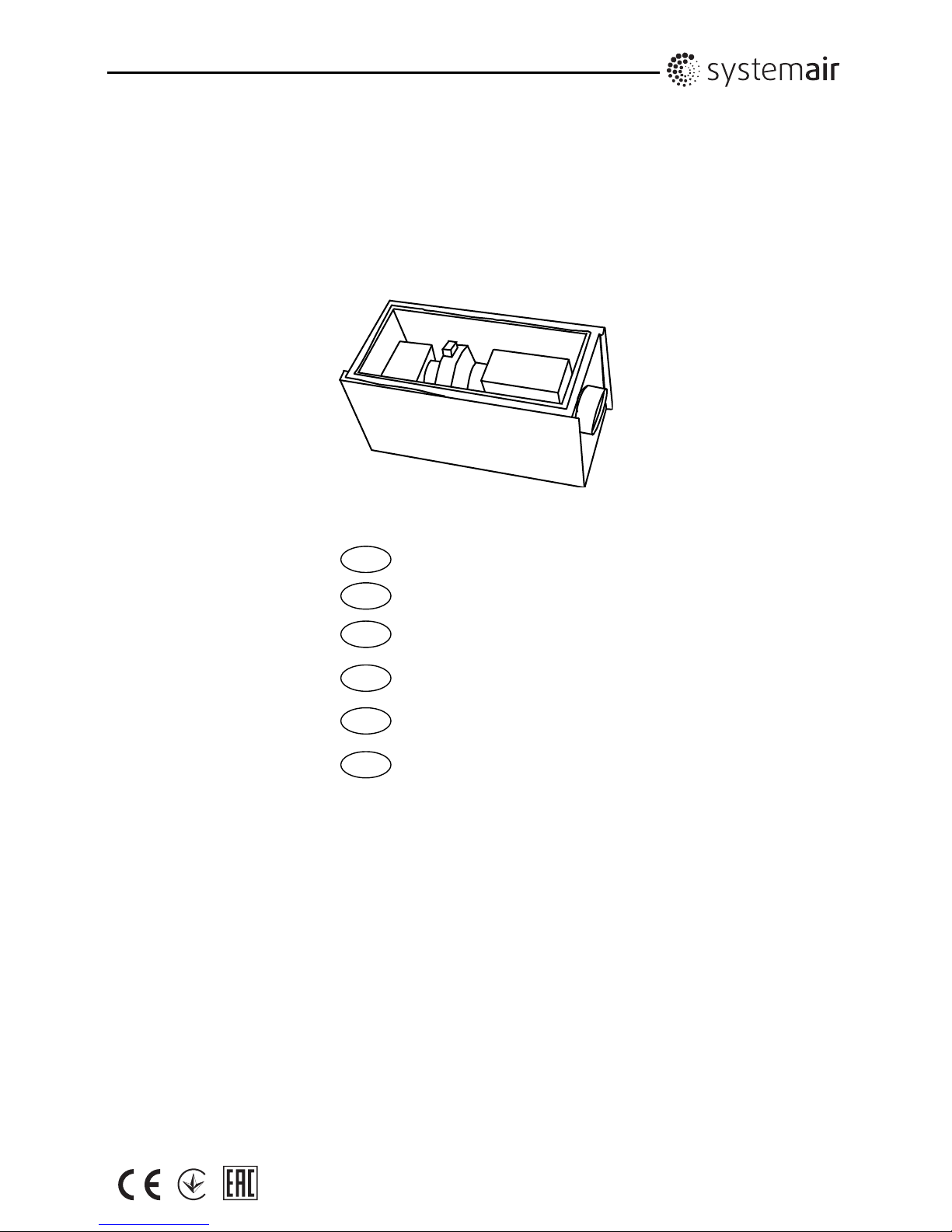
TLP 125/1,2 TLP 160/2,1
TLP 200/3,0 TLP 200/5,0 TLP 200/5,4 TLP 315/6,0
TLP 315/9,0
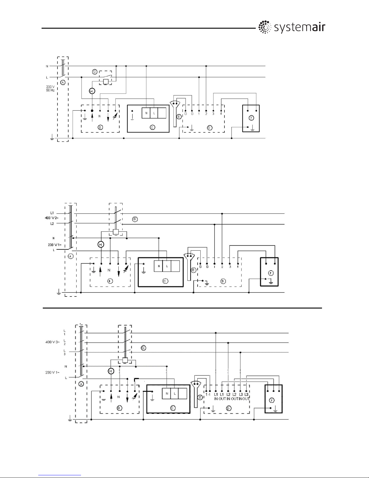
A Main switch
B Thyristor (Fan control)
C Fan
D Heat regulator (Pulser or TTC 2000)
E Temperature sensor
F Heater battery
G Relay
H Air flow guard (pressure sensor)
A Main switch
B Thyristor (Fan control)
C Fan
D Heat regulator (Pulser 230/400)
E Temperature sensor
F Heater battery
G Relay
H Air flow guard (pressure sensor)
Page 3

Original
3
GB IE
Declaration of Conformity
Manufacturer
Systemair Sverige AB
Industrivägen 3
SE-739 30 Skinnskatteberg SWEDEN
Office: +46 222 440 00 Fax: +46 222 440 99
www.systemair.com
hereby confirms that the following products:
Air handling unit: TLP125-315
(The declaration applies only to product in the condition it was delivered in and installed in the facility in
accordance with the included installation instructions. The insurance does not cover components that are added
or actions carried out subsequently on the product)
Comply with all applicable requirements in the following directives
Machinery Directive 2006/42/EC
Low Voltage Directive 2014/35/EU
EMC Directive 2014/30/EU
The following harmonized standards are applied in applicable parts:
EN ISO 12100:2010 Safety of machinery - General principles for design – Risk assessment and risk reduction.
EN 13857 Safety of machinery – Safety distances to prevent hazard zones being reached by upper
or lower limbs.
EN 60204-1 Safety of machinery – Electrical equipment of machines – Part 1: General requirements
EN 60 335-1 Household and similar electrical appliances – Safety Part 1: General requirements.
EN 60 335-2-80 Household and similar electrical appliances – Safety – Part 2-80: Particular requirements
for fans.
EN 50 106:2007 Safety of household and similar appliances – Particular rules for routine tests referring to
appliances under the scope of EN 60 335-1 and EN 60967.
EN 60529 Degrees of protection provided by enclosures (IP Code).
EN 62233 Measurement methods for electromagnetic fields of household appliances and similar
apparatus with regard to human exposure.
EN 61000-6-2 Electromagnetic compatibility (EMC) – Part 6-2: Generic standards – Immunity for
industrial environments.
EN 61000-6-3 Electromagnetic compatibility (EMC) – Part 6-3: Generic standards – Emission standards
for residential, commercial and light-industrial environments.
Skinnskattberg 26-01-2017
Mats Sándor
Technical Director
Page 4

Original
4
GB IE
Safety Information
This machinery must not be put into operation until prior
to reading mounting instructions and safety information.
All units are intended for transportation of air in air
handling systems. They are meant to be used after
building them into machines or duct systems or after
contact protection grid have been installed. (EN ISO
13857). The unit must be connected to ducts on both
sides (inlet/outlet). When there is a risk of water
entering the motor, via the ducts, external protection is
required. No moving parts shall be accessible after
installation. The units are not to be used in hazardous
environments or connected to flues. The TLP units must
not be installed outdoors. Safety accessories (i.e. motor
protection, safety grille) may not be dismounted, short
cut or disconnected. CAUTION Before servicing or
maintenance, switch off power, (all-pole circuit breaker),
and make sure the impeller has come to a standstill.
CAUTION The equipment can have sharp edges and
corners which may cause injuries.CAUTION, be careful
when opening the units service-hatches in case the unit
is mounted with the inspection hatch downward.
Transportation and Storage
The TLP units are packaged at the factory to withstand
normal transport handling. When handling the goods use
suitable lifting equipment in order to avoid damage to
equipment and personnel. Do not lift the unit by the
connecting cable, connection box, impeller or inlet cone.
Avoid blows and shock loads. Store the unit in a dry
place protected from weather and dirt until final
installation
.
Installation
Refer to Safety information above. Installation, electrical
connection and commissioning are only to be carried out
by authorised personnel and in accordance with
requirements and demands. Electrical connections are
made according to the wiring diagram, markings on
terminal blocks or on cable. All 3 phase units are
delivered from factory in 400V 3~ connection. CAUTION
do not use metal compression gland fittings with plastic
terminal boxes. Use a dummy plug seal for the
compression gland fitting as well. If the wiring to the K
fan in the unit is carried out using cables with diameter
12-14 mm, the entrance bushing must be replaced
(applies to type K). Assemble the TLP unit in the
direction of the airflow (see arrow on unit). The unit must
be installed so that vibrations are not transmitted to duct
systems or the frame of the building. (Suitable
accessories like fast clamps and diffusers are available).
Make sure the assembly of the fan is firmly fixed and
stable. The smaller sized of TLP 125 to 200, can be
mounted upside down in false ceilings. In this case the
heater must be rotated so that the connection box with
the overheating protection switches face upward or to
the side. NB TLP 315 cannot be placed upside down.
The TLP units must be mounted so that service and
maintenance can be performed easily and safely.
Disturbing noise can be avoided by installing silencer
(available accessory).
For frequency regulation an all pole sinus filter must be
mounted between motor and frequency controller
(version all poles: phase to phase, phase to earth). The
TLP unit is meant for continuous use within the
temperature range stated.
The fans inside the TLP unit are equipped with manual
thermal contacts (reset by cutting the current, motor
protection SP1), must be taken into consideration when
connecting surrounding equipment with automatic on/off
function.
Operation
Before initial operation, check the following:
- Electrical connection has been properly completed.
- Protective conductor has been connected.
- Safety devices in place (protection grid)
- Leftover installation materials and foreign materials
have been removed from the casing.
When putting into operation, check thefollowing:
- Connection data corresponds to the specifications on
the nameplate: Maximum voltage +6%, -10%, according
to IEC 38. Rated current must not be exceeded with
more than 5% at rated voltage. CAUTION when speed
regulating by reducing the voltage the motor current may
exceed the rated current at a lower voltage. In this case
the motor windings are protected by the thermal contact.
- Smoothness of motor operation, (no abnormal noises).
-Fans must only be operated by a person that has
sustainable knowledge or education within this field or
handling must be carried out with the supervision of such
person.
Maintenance, Service and Repair
Before maintenance, service or repair, make sure that:
- Power supply is interrupted (all-pole circuit breaker).
- Fan impeller has come to a complete standstill
- Observe personnel safety regulations!
The fan in the unit should be cleaned when necessary,
at least 1/year to avoid imbalance and unnecessary
damage to the bearings. Periodical changing of the filter
inside the unit will prolong the time interval between
each cleaning of the fan. The fan bearings are
maintenance free and should only be replaced if
damaged. Do not use a high-pressure cleaner (steam
jet) when cleaning the unit. Listen for abnormal operating
noise.
Resetting of the thermal trips
Manual thermal trips (SP1) are reset by disconnecting
the mains for approx. 10-20min.
Make sure the unit has not been blocked or that the
motor protection has tripped. Contact the supplier if the
motor does not start after controlling and/or resetting the
motor protection.
Page 5
5
SE
Försäkran om överensstämmelse
Tillverkare
Systemair Sverige AB
Industrivägen 3
739 30 Skinnskatteberg
Tel: +46 222 440 00 Fax: +46 222 440 99
www.systemair.com
Försäkrar härmed att produkter:
Luftbehandlingsaggregat: TLP125-315
(Försäkran gäller endast för produkt i leveransutförande och installerad i anläggning i enligt medlevererad
montageanvisning. Försäkring omfattar inte komponenter som läggs till eller åtgärder som därefter genomförs på
produkt)
Överensstämmer med alla tillämpliga bestämmelser i följande direktiv:
Maskindirektivet 2006/42/EG
Lågspänningsdirektivet 2014/35/EU
EMC direktivet 2014/30/EU
Följande harmoniserade standarder är tillämpade i tillämpliga delar:
EN ISO 12100-2010 Maskinsäkerhet – Generella konstruktionsprinciper – riskbedömning och riskminskning.
EN 14121-1:2007 Maskinsäkerhet – Riskbedömning – Del 1: Principer.
EN 13857 Maskinsäkerhet – Skyddsavstånd för att hindra fara riskområden med övre eller nedre
extremiteterna.
EN 60204-1 Maskinsäkerhet – Maskiners elutrustning – Del 1: Allmänna fordringar
EN 60 335-1 Elektriska hushållsapparater och liknande bruksföremål – Säkerhet Del 1: Allmänna krav.
EN 60 335-2-80 Elektriska hushållsapparater och liknande bruksföremål – Säkerhet - Del 2-80: Särskilda
fordringar på fläktar.
EN 50 106:2007 Elektriska hushållsapparater och liknande bruksföremål – Särskilda regler för
rutinundersökningar med hänvisning till apparater som omfattas av EN 60 335-1 och EN
60967.
EN 60529 Kapslingsklasser för elektrisk materiel (IP-beteckning).
EN 62233 Hushållsapparater och liknande bruksföremål – Mätning av elektromagnetiska fält med
avseende på exponering
EN 61000-6-2 Elektromagnetisk kompatibilitet (EMC) – Del 6-2: Generella fordringar – Immunitet hos
utrustning i industrimiljö.
EN 61000-6-3 Elektromagnetisk kompatibilitet (EMC) – Del 6-3: Generella fordringar – Emission normer
för bostäder, kommersiella och liknande miljöer.
Skinnskattberg 26-01-2017
Mats Sándor
Teknisk Direktör
Page 6

6
SE
Säkerhet
Aggregatet får ej tas i bruk innan installationsanvisning
och säkerhetsanvisning har beaktats.
Luftbehandlingsaggregat för ventilation i
luftbehandlingssystem med luft från icke
explosionsfarligt utrymme. TLP luftbehandlingsaggregat
är produkter som är avsedda att tas i bruk endast efter
inbyggnad, kanalanslutning eller att produkten försetts
med beröringsskydd. (EN ISO 13857). Kanaler ska
monteras på aggregatets sug-/tryck-sida, när risk finns
för att vatten via kanaler kan tränga in i fläktmotorn så
måste någon form av externt skydd monteras på
kanaler. Efter Installation/kanalanslutning ska beröring
av rörliga delar ej vara möjlig. TLP får ej användas i
explosiv miljö eller anslutas till rökgaskanal. Enheten får
ej monteras utomhus. Säkerhetsdetaljer (t ex
beröringsskydd) får ej demonteras, förbikopplas eller
bortkopplas. OBS! Innan service och underhåll påbörjas
måste enheten göras spänningslös, allpolig brytning, och
fläkthjulet ha stannat. OBS! Enheten kan ha vassa
kanter och hörn, vilket kan orsaka skärskador. OBS!
Iakttag försiktighet vid öppnande av serviceluckan om
aggregatet monterats med serviceluckan nedåt.
Transport och lagring
TLP aggregaten som levereras från Systemair är emballerade för att klara normal godshantering. Vid godshantering använd lämplig lyftanordning för att undvika
skador på utrustning och personer. OBS! Lyft ej enheten
i motorkabel, kopplingsdosa, fläkthjul eller
insugningskona. Undvik slag och stötar. Aggregatet ska
lagras torrt och väderskyddat och skyddas från smuts
och damm före slutlig installation.
Installation
Se även avsnitt säkerhet. Installation, elektrisk
anslutning samt idrifttagande ska göras av behörig
installatör och utföras i enlighet med för installationen
gällande föreskrifter och krav. Elektrisk anslutning ska
göras enligt kopplings-schema, märkning på
kopplingsplint eller på kabel. Alla 3-fas aggregat är
kopplade 400V 3~ från fabrik. OBS! Använd ej
förskruvningar av metall om kopplingsdosan är av plast.
Täta ev. tomma förskruvningshål med blindplugg. Om
fast installation sker med kabel som har diam. 12-14mm
så måste införings-bussningen bytas, gäller enheter
innehållande fläkt typ K. Montera TLP enheten i rätt
luftriktning (se luftriktningspil). Aggregatet ska monteras
så att vibrationer ej kan överföras till kanalsystem och
byggnadsstomme. (För ändamålet finns fästklammer
som tillbehör. De mindre storlekarna av TLP kan också
placeras upp och ned i undertak. Det kräver dock att
värmaren vrids i lådan så att överhettningsskyddets
placering alltid är uppåt eller åt sidan för rätt funktion.
OBS! TLP 315 får inte placeras upp och ned. Aggregatet
ska monteras på ett stadigt och stabilt sätt. Montera
enheten så att service och underhåll kan utföras på ett
enkelt och säkert sätt. Ljudproblem kan förebyggas
genom installation av ljuddämpare (finns som tillbehör).
För frekvensreglering gäller att ett allpoligt sinusfilter
måste monteras mellan motor och frekvensstyrning
(version allpolig: fas till fas, fas till jord). TLP aggregaten
är avsedda för kontinuerlig drift inom angivna
temperaturområden.
För kopplingschema gäller:
A Main swith = Allpolig brytare
B Thyristor (Fan control) = Tyristor (Fläktreglering)
C Fan = Fläkt
D Heat regulator = Värmestyrning
E Temperature sensor = Temperatursensor
F Heater battery = Värmare,
G Relay = Relä
H Air flow guard (pressure control) = Flödesvakt
(tryckvakt)
Fläkten i TLP aggregatet är försedd med manuell
termokontakt (återställs genom att fläkten görs strömlös,
motorskydd typ SP1). Detta måste beaktas vid
inkoppling av kringutrustning som bryter och kopplar in
strömmen automatiskt.
Drift
Före idrifttagande kontrollera följande:
-Elektrisk anslutning är slutförd.
-Skyddsjorden ansluten.
-Säkerhetsutrustning monterad (beröringsskydd).
-Inga främmande föremål finns i enheten.
Vid idrifttagande kontrollera följande:
Att uppmätta data ej överstiger på aggregatets typskylt
angivna märkdata: Maximalt tillåten spänning +6%, 10%, enligt IEC 38. Märkströmmen får ej överskridas
med mer än 5% vid märkspänning. OBS! Vid
varvtalsreglering genom spänningssänkning kan
strömmen i motorn vid en lägre spänning överstiga den
angivna märkströmmen. I dessa fall skyddas
motorlindingen av termokontakten!
-Att rotationsriktning på fläkthjulet överensstämmer med
rotationsriktningspilen (3-fas).
-Att inga missljud hörs från enheten.
- Fläktar i drift får endast handhas av person som har
kunskap eller utbildning för detta, eller att handhavande
sker under överinseende av sådan person.
Underhåll, service och reparation
Innan service, underhåll eller reparation påbörjas måste:
-Fläkten göras spänningslös (allpolig brytning).
-Fläkthjulet stannat.
-Gällande säkerhetsföreskrifter beaktats.
Fläkten i aggregatet ska rengöras vid behov, dock minst
1 gång/år för att undvika obalans med onödiga
lagerskador som följd. Byte av filtret i aggregatet med
jämna mellanrum gör att rengöringsintervallet kan
förlängas. ( Det kan i vissa fall vara befogat att använda
andningsskydd vid byte av filter). Fläktens lager är
underhållsfria och ska endast bytas vid behov. Vid
rengöring av fläkten får högtryckstvätt ej användas.
Rengöring måste ske försiktigt så att fläkthjulets
balansvikter ej rubbas eller fläkthjulet deformeras.
Kontrollera att inga missljud hörs.
Om termokontakten har löst ut gäller följande:
- Manuell termokontakt (typ SP1) återställs genom att
bryta strömmen under ca: 10-20 min.
Kontrollera att fläkthjulet inte är blockerat eller att
motorskyddet har löst ut. Om fläkten efter kontroll
och/eller återställning av motorskyddet ej startar
kontakta er installatör/inköpsställe.
Page 7

7
FI
Vaatimustenmukaisuusvakuutus
Valmistaja
Systemair Sverige AB
Industrivägen 3
SE-739 30 Skinnskatteberg RUOTSI
Toimisto: +46 222 440 00 Faksi: +46 222 440 99
www.systemair.com
vakuuttaa täten, että seuraavat tuotteet:
Ilmanvaihtokoneet: TLP125-315
(Vakuutus on voimassa vain tuotteelle, joka on samassa kunnossa kuin toimitettaessa ja asennettu mukana
toimitettujen asennusohjeiden mukaisesti. Vakuutus ei kata myöhemmin tuotteeseen asennettuja komponentteja
tai tuotteelle tehtyjä toimenpiteitä)
noudattavat seuraavien direktiivien vaatimuksia soveltuvin osin
Konedirektiivi 2006/42/EY
Pienjännitedirektiivi 2014/35/EU
EMC-direktiivi 2014/30/EU
Seuraavia yhdenmukaistettuja standardeja on käytetty soveltuvin osin:
EN ISO 12100-2010 Koneiden turvallisuus – Yleiset suunnitteluperiaatteet – Riskiarviointi ja riskien
vähentäminen.
EN 13857 Koneturvallisuus. Turvaetäisyydet yläraajojen ja alaraajojen ulottumisen estämiseksi
vaaravyöhykkeille.
EN 60204-1 Koneturvallisuus. Koneiden sähkölaitteet. Osa 1: Yleiset vaatimukset.
EN 60 335-1 Kotitaloussähkölaitteiden ja vastaavien turvallisuus. Osa 1: Yleiset vaatimukset
EN 60 335-2-80 Kotitaloussähkölaitteiden ja vastaavien turvallisuus. Osa 2-80: Puhaltimia koskevat
erityisvaatimukset.
EN 50 106:2007 Kotitaloussähkölaitteiden ja vastaavien turvallisuus. Standardien EN 60 335-1 ja EN
60967 piiriin kuuluville laitteille suoritettavien rutiinitestien erityisohjeet.
EN 60529 Sähkölaitteiden kotelointiluokat (IP-koodi).
EN 62233 Kotitaloussähkölaitteiden ja vastaavien sähkömagneettisten kenttien aiheuttaman
altistumisen mittausmenetelmät.
EN 61000-6-2 Sähkömagneettinen yhteensopivuus (EMC). Osa 6-2: Yleiset standardit. Häiriönsieto
teollisuusympäristöissä.
EN 61000-6-3 Sähkömagneettinen yhteensopivuus (EMC). Osa 6-3: Yleiset standardit. Häiriönpäästöt
kotitalous-, toimisto- ja kevyen teollisuuden ympäristöissä.
Skinnskattberg 26-01-2017
Mats Sándor
Tekninen johtaja
Page 8

8
FI
Turvallisuustiedot
Lue asennus- ja turvaohjeet huolella ennen koneen
käyttöönottoa.
Kaikki yksiköt on tarkoitettu ilman siirtämiseen
ilmankäsittelyjärjestelmissä. Ne on tarkoitettu
käytettäväksi koneeseen tai kanavistoon
sisäänrakennettuna tai suojaverkolla varustettuna. (EN
ISO 13857). Yksikkö tulee liittää kanavaan molemmilta
puolilta (tulo/lähtö). Jos moottoriin voi päästä vettä
kanaviston kautta, tarvitaan ulkopuolinen suojaus.
Liikkuviin osiin koskettaminen ei saa olla mahdollista
asennuksen jälkeen. Yksiköitä ei saa käyttää
räjähdysvaarallisissa ympäristöissä eikä liittää
savuhormeihin. TLP-yksiköitä ei saa asentaa ulkotiloihin.
Suojavarusteita (esim. moottorinsuojaus, suojaritilä) ei
saa irrottaa, ohittaa tai kytkeä irti. HUOM. Katkaise
virransyöttö turvakytkimellä ennen huolto- tai
kunnossapitotöiden aloitusta ja varmista, että siipipyörä
on pysähtynyt. HUOM. Laitteissa voi olla teräviä reunoja
ja kulmia, jotka voivat aiheuttaa tapaturmia. HUOM. Ole
varovainen yksikön huoltoluukkuja avatessasi, jos
yksikkö on asennettu tarkastusluukku alaspäin.
Kuljetus ja varastointi
TLP-yksiköt on pakattu tehtaalla kestämään normaalia
kuljetuskäsittelyä. Käytä sopivia nostolaitteita pakkausten
käsittelyyn välttääksesi henkilö- ja omaisuusvahingot. Älä
nosta yksikköä kytkentäkaapeleista, kytkentärasiasta,
siipipyörästä tai imukartiosta. Varo altistamasta iskuille ja
voimakkaille tärähdyksille. Säilytä yksikkö asennukseen
saakka kuivassa paikassa säältä ja lialta suojattuna.
Asennus
Lue turvaohjeet. Asennuksen, sähkökytkennän ja
käyttöönoton saa tehdä vain valtuutettu asentaja
annettujen ohjeiden ja vaatimusten mukaisesti.
Sähkökytkennät tehdään kytkentäkaavion sekä
kytkentärimoissa ja kaapeleissa olevien merkintöjen
mukaisesti. Kaikki 3-vaiheiset yksiköt toimitetaan
tehtaalta 400 V 3-vaiheliitännällä. HUOM Älä käytä
metallisia kaapeliläpivientejä muovisissa
kytkentärasioissa. Tulppaa mahdolliset ylimääräiset
kaapeliläpiviennit suojatulpilla. Jos yksikön K-puhaltimen
johdotus tehdään ø 12-14 mm kaapeleilla,
kaapeliläpivienti tulee vaihtaa (koskee tyyppiä K).
Asenna TLP-yksikkö ilmavirtaan nähden oikein päin
(katso yksikön nuoli). Yksikkö on asennettava niin, ettei
värinöitä siirry kanavistoon tai rakenteisiin.
(Lisävarusteena on saatavana mm. kanava- tai joustavia
liittimiä). Varmista, että puhallin on kunnolla ja tukevasti
kiinnitetty. TLP:n pienemmät koot 125 – 200 voidaan
asentaa ylösalaisin alakattoihin. Tässä tapauksessa
lämmitin pitää kääntää niin, että liitäntäkotelo
ylikuumenemissuojakytkimineen tulee ylöspäin tai sivulle.
Mallia NB TLP 315 ei voi asentaa ylösalaisin. TLPyksiköt on asennettava niin, että huolto- ja
kunnossapitotyöt voidaan suorittaa helposti ja
turvallisesti. Häiritsevä melu voidaan estää asentamalla
äänenvaimennin (saatavana lisävarusteena).
Taajuudensäätöä varten moottorin ja taajuudensäätimen
välille on asennettava kaikkinapainen siniaaltosuodatin
(kaikkinapainen versio: vaiheesta vaiheeseen ja
vaiheesta maadoitukseen). TLP-yksikkö on tarkoitettu
jatkuvaan käyttöön ilmoitetulla lämpötila-alueella.
Alla oleva viittaa kytkentäkaavioon:
A Main swith = Pääkytkin
B Thyristor (Fan control) = Tyristori (puhaltimen ohjaus)
C Fan = Puhallin
D Heat regulator = Lämpötilasäädin
E Temperature sensor = Lämpötila-anturi
F Heater battery = Lämmityspatteri
G Relay = Rele
H Air flow guard (pressure control) = Virtausvahti
(paine-erokytkin)
TLP-yksikön sisällä olevat puhaltimet on varustettu
manuaalisilla lämpökatkaisimilla (palautetaan
katkaisemalla virta, moottorinsuoja SP1) tämä tulee ottaa
huomioon, kun kytketään oheislaitteita automaattiseen
on/off –toimintaan.
Käyttö
Tarkista seuraavat ennen käyttöönottoa:
- Sähkökytkennät on tehty oikein.
- Suojamaadoitus on kytketty.
- Suojavarusteet ovat paikoillaan (suojaverkko)
- Ylimääräiset asennustarvikkeet ja vieraat esineet on
poistettu kotelosta.
Tarkista seuraavat käyttöönoton aikana:
- Mitatut arvot vastaavat tyyppikilven erittelyjä: suurin
sallittu jännite +6 %, -10 %, standardin IEC 38 mukaan.
Nimellisvirta ei saa ylittyä yli 5 %:lla nimellisjännitteellä.
HUOM. Kun nopeuttaa säädetään pienentämällä
jännitettä, moottorin virta saattaa ylittää nimellisvirran
pienemmällä jännitteellä. Tässä tapauksessa
lämpökatkaisin suojaa moottorin käämityksiä.
- Moottorin toiminnan tasaisuus (ei vieraita ääniä).
- Puhaltimia saavat käyttää ainoastaan henkilöt, joilla on
tarpeeksi tietoa tai koulutusta tällä alalla, tai käytön tulee
tapahtua tällaisen henkilön valvonnassa.
Kunnossapito, huolto ja korjaus
Varmista ennen kunnossapito-, huolto- ja korjaustöiden
aloittamista, että:
- Jännitteensyöttö on katkaistu (turvakytkimellä).
- Siipipyörä on pysähtynyt
- Noudata turvaohjeita!
Yksikön puhallin tulee puhdistaa tarvittaessa, kuitenkin
vähintään kerran vuodessa epätasapainon ja laakerien
turhan kulumisen välttämiseksi. Suodattimen vaihto
määräajoin pidentää puhaltimen puhdistusvälejä.
Puhaltimen laakerit ovat huoltovapaita ja ne tulee vaihtaa
vain, jos ne vaurioituvat. Älä käytä paine- tai
höyrypesuria yksikön puhdistukseen. Tarkasta, ettei
puhaltimesta kuulu epänormaalia melua.
Lämpökatkaisimien palautus
Manuaaliset lämpökatkaisimet (SP1) palautetaan
katkaisemalla jännitteensyöttö n. 10-20 minuutiksi.
Varmista, että yksikkö ei ole tukkeutunut ja että
moottorinsuoja ei ole lauennut. Ota yhteyttä toimittajaan,
ellei moottori käynnisty tarkastuksen ja/tai
moottorinsuojan palautuksen jälkeen.
Page 9

9
FR
Déclaration de conformité
Le fabricant :
Systemair Sverige AB
Industrivägen 3
SE-739 30 Skinnskatteberg SUÈDE
Téléphone: +46 222 440 00 Fax: +46 222 440 99
www.systemair.com
certifie par les présentes que le produit suivant:
Centrale de traitement d’air: TLP125-315
(La déclaration s’applique exclusivement au produit dans l’état où il a été livré et installé sur site conformément
aux instructions jointes. L’assurance ne couvre pas les composants ajoutés ou les interventions effectuées
ultérieurement sur le produit.)
Est conforme à l’ensemble des exigences des directives suivantes
Directive machines 2006/42/EC
Directive basse tension 2014/35/EU
Directive CEM 2014/30/EU
Les normes harmonisées suivantes sont d’application pour les parties concernées:
EN ISO 12100-2010 Sécurité de la machine – Principes généraux de conception – Appréciation du risque et
reduction du risqué.
EN 13857 Sécurité des machines – distances de sécurité pour les membres supérieurs ou inférie.
EN 60204-1 Sécurité des machines – Équipement électrique des machines – Partie 1 : règles
generals.
EN 60 335-1 Appareils électrodomestiques et analogues – Sécurité. Partie 1: Généralités.
EN 60 335-2-80 Appareils électrodomestiques et analogues – Sécurité – Partie 2-80: règles particulières
pour les ventilateurs.
EN 50 106:2007 Sécurité des appareils électrodomestiques et analogues – Règles particulières pour les
essais de série concernant les appareils dans le domaine d’application des normes EN
60 335-1 et EN 60967.
EN 60529 Degrés de protection procurés par les enveloppes (code IP).
EN 62233 Méthodes de mesure des champs électromagnétiques des appareils électroménagers et
similaires en relation avec l’exposition humaine.
EN 61000-6-2 Compatibilité électromagnétique (CEM) – Partie 6-2: exigences générales – Immunité des
appareils en environnements industriels.
EN 61000-6-3 Compatibilité électromagnétique (CEM), Partie EN 6-3: Normes génériques – Émissions
standards pour les environnements résidentiels, commerciaux et l'industrie légère.
Skinnskattberg 26-01-2017
Mats Sándor
Directeur technique
Page 10

10
FR
Sécurité
Lire impérativement les instructions de montage et les
consignes de sécurité avant la mise en service de cet
équipement.
Les centrales sont destinées à transporter l’air dans les
systèmes de ventilation et à être intégrées dans des
machines ou réseaux de gaines, ou utilisées de manière
autonome pour autant qu’elles soient munies d’une grille de
protection (EN ISO 13857). La centrale doit être raccordée à
des gaines des deux côtés (entrée et sortie). En cas de
risque d’infiltration d’eau dans le moteur via les gaines,
prévoir une protection externe. Aucun élément mobile ne
doit être accessible une fois l'installation terminée. Ne pas
utiliser les centrales dans des environnements explosibles
et ne pas les raccorder à un conduit de cheminée. Ne pas
installer les centrales TLP à l’extérieur. Ne pas démonter,
court-circuiter ni déconnecter les dispositifs de sécurité (par
ex. protection moteur, grille de sécurité). ATTENTION.
Avant toute intervention sur les ventilateurs, couper
l'alimentation électrique principale et attendre l'arrêt complet
des pièces en mouvement. ATTENTION. Les angles et
bords des équipements peuvent être source de blessures.
ATTENTION. Ouvrir prudemment la porte d’inspection de la
centrale lorsqu’elle s’ouvre vers le bas.
Transport et stockage
Les centrales TLP sont emballées en usine pour supporter
des conditions de stockage, de manutention et de transport
normales. Utiliser des équipements de manutention adaptés
pour garantir la sécurité du personnel et des produits. Ne
pas soulever les équipements par leur câble d’alimentation
électrique, boîtier de connexion, hélice ou cône d’entrée.
Éviter tout choc. Avant installation, stocker les centrales à
l’intérieur, à l'abri de l'humidité et de la poussière.
Installation
Voir les consignes de sécurité ci-dessus. L'installation, le
branchement électrique et la mise en service doivent être
effectués selon les règles de l’art par un professionnel
qualifié. Le raccordement électrique doit être effectué
conformément au schéma de câblage et en respectant le
marquage des câbles ou borniers. Les centrales triphasées
sont livrées en standard en version 400 V 3~. ATTENTION
– Ne pas utiliser de presse-étoupe métallique avec les
boîtes de raccordement en plastique. Utiliser également une
fiche isolante pour le presse-étoupe. Lorsque le ventilateur
K de la centrale est connecté par des câbles de Ø12 à
14 mm, remplacer la bague d’entrée (concerne le type K).
Assembler la centrale TLP dans le sens du débit d'air
(flèche sur l’appareil). Installer la centrale de façon à éviter
la transmission de vibrations dans le réseau de gaines ou à
la structure du bâtiment (par ex. en installant des
manchettes ou des plots antivibratiles). Vérifier que le
ventilateur est stable et bien fixé. Les petits modèles – TLP
125 à 200 – se montent également en faux plafond, trappe
vers le bas. Dans ce cas, tourner la batterie chauffante pour
que le boîtier de raccordement contenant les dispositifs antisurchauffe soit orienté vers le bas ou le côté. Remarque : la
centrale TLP 315 ne peut pas être installée trappe vers le
bas. Les centrales TLP doivent être montées de manière à
faciliter toute intervention ultérieure de maintenance. Des
silencieux spéciaux proposés en option permettent d’éviter
les bruits gênants.
Dans le cas de variation de fréquence, un filtre multipolaire
à sinusoïde doit être installé entre le variateur et le
ventilateur (version tous pôles : phase à phase, phase à
terre). Les centrales TLP sont conçues pour une utilisation
permanente dans la limite des températures de
fonctionnement recommandées.
Légendes du schéma de câblage :
A Main switch = Coupure de proximité principal
B Thyristor (Fan control) = Variateur ventilateur
C Fan = Ventilateur
D Heat regulator = Régulateur batterie (triac)
E Temperature sensor = Sonde de température
F Heater battery = Batterie électrique
G Relay = Relais
H Air flow guard (pressure control) = Pressostat (contrôle de
présence de débit d’air)
Les ventilateurs équipés d’une protection thermique à
réarmement manuel (par coupure d’alimentation, protection
moteur SP1) doivent être pris en considération lors du
raccordement d’équipements à fonction marche / arrêt
automatique.
Fonctionnement
Avant la première mise en route, vérifier les points suivants :
- Le raccordement électrique doit être effectué selon les
règles de l'art.
- Les conducteurs électriques doivent être bien isolés.
- Les protections mécaniques doivent être en place (grille de
protection).
- Les résidus des matériels d'installation et objets étrangers
doivent être enlevés.
Lors de la mise en route, vérifier les points suivants :
- Les caractéristiques électriques doivent correspondre à
celles figurant sur la plaque signalétique : écart de tension
entre +6% et -10% suivant la norme IEC38. Courant
nominal ne dépassant pas de 5% la valeur nominale à la
tension nominale. ATTENTION. En cas de régulation de la
vitesse par réduction de la tension, l’alimentation du moteur
peut dépasser l’intensité nominale à une tension inférieure.
Dans ce cas, les bobinages du moteur sont protégées par le
thermocontact.
- Vérifier que le moteur fonctionne avec régularité (sans de
bruits anormaux).
-L’utilisation et la manipulation des ventilateurs seront
exclusivement effectuées par du personnel compétent ou
sous sa surveillance.
Maintenance, entretien et réparation
Avant toute intervention de réparation ou de maintenance,
vérifier les points suivants :
- Mettre l’équipement hors tension (coupure multipolaire).
- Attendre l’arrêt complet de l'hélice.
- Respecter les consignes de sécurité.
Le ventilateur de la centrale sera nettoyé aussi souvent que
nécessaire et au minimum une fois par an pour éviter un
déséquilibrage et l’usure précoce des roulements. Pour
espacer les entretiens du ventilateur, remplacer
régulièrement le filtre à l’intérieur de la centrale. Les
roulements ne nécessitent ni entretien ni graissage et ne
doivent être remplacés que s’ils sont endommagés. Ne pas
utiliser de système à haute pression ou à vapeur pour
nettoyer le ventilateur. Vérifier qu’aucun bruit anormal n’est
détecté. Réarmement de la protection thermique
Pour réarmer manuellement l’équipement après le
déclenchement de la protection thermique (SP1), le mettre
hors tension pendant environ 10 à 20 minutes.
Vérifier que l’hélice n’est pas bloquée et que le
thermocontact du moteur ne s’est pas déclenché. Si le
moteur persiste à ne pas démarrer après les vérifications cidessus ou le réarmement du thermocontact, contactez votre
distributeur.
Page 11

11
PL
Deklaracja zgodności
Producent
Systemair Sverige AB
Industrivägen 3
SE-739 30 Skinnskatteberg SZWECJA
Biuro: +46 222 440 00 Faks: +46 222 440 99
www.systemair.com
niniejszym potwierdza, że następujące produkty:
Centrala wentylacyjna: TLP125-315
(Deklaracja dotyczy wyłącznie produktów w niezmienionym stanie od czasu dostawy, zainstalowanych w
obiekcie zgodnie z dołączoną instrukcją montażu. Ubezpieczenie nie obejmuje dodanych elementów ani
późniejszych modyfikacji produktów).
Spełniają wszystkie obowiązujące postanowienia następujących dyrektyw
Dyrektywa maszynowa 2006/42/WE
Dyrektywa niskiego napięcia 2014/35/EU
Dyrektywa kompatybilności elektromagnetycznej 2014/30/EU
W odpowiednich częściach zastosowano następujące normy zharmonizowane:
EN ISO 12100-2010 Bezpieczeństwo maszyn – Ogólne zasady projektowania – Ocena ryzyka i zmniejszanie
ryzyka.
EN 13857 Bezpieczeństwo maszyn – Odległości bezpieczeństwa uniemożliwiające sięganie
kończynami górnymi i dolnymi do stref niebezpiecznych.
EN 60204-1 Bezpieczeństwo maszyn – Wyposażenie elektryczne maszyn – Część 1: Wymagania
ogólne.
EN 60335-1 Bezpieczeństwo elektryczne urządzeń domowych i podobnych – Część 1: Wymagania
ogólne.
EN 60335-2-80 Bezpieczeństwo elektryczne urządzeń domowych i podobnych – Część 2-80: Wymagania
szczegółowe dla wentylatorów.
EN 50106:2007 Bezpieczeństwo elektrycznych przyrządów do użytku domowego i podobnego –
Postanowienia szczegółowe dotyczące badań wyrobu przyrządów wchodzących w zakres
EN 60 335-1 i EN 60967.
EN 50529 Stopnie ochrony zapewnianej przez obudowy (kod IP).
En 62233 Metody pomiaru pól elektromagnetycznych elektrycznego sprzętu do użytku domowego i
podobnego z uwzględnieniem naraż
ania człowieka.
EN 61000-6-2 Kompatybilność elektromagnetyczna (EMC) – Część 6-2: Normy ogólne – Odporność
w środowiskach przemysłowych.
EN 61000-6-3 Kompatybilność elektromagnetyczna (EMC) – Część 6-3: Normy ogólne – Wymagania
dotyczące emisyjności w środowisku mieszkalnym, handlowym i lekko
uprzemysłowionym.
Skinnskattberg 26-01-2017
Mats Sándor
Dyrektor Techniczny
Page 12

12
PL
Informacje dotyczące bezpieczeństwa
Przed uruchomieniem tego urządzenia należy bezwzględnie
przeczytać instrukcję montażu i ostrzeżenia dotyczące
bezpieczeństwa.
Wszystkie urządzenia są przeznaczone do przetłaczania
powietrza w systemach wentylacji bytowej. Wentylatory można
eksploatować po wbudowaniu w instalacje albo w urządzenia,
których część mają stanowić albo po zainstalowaniu osłon
ochronnych na wlotach/ częściach wirujących. (EN ISO 13857).
Urządzenia muszą być obustronnie podłączone do instalacji
kanałowej (wlot/wylot). Jeśli istnieje ryzyko przedostawania się
kanałami wody do wnętrza wentylatora, należy zainstalować
odpowiednie zabezpieczenie. Po zainstalowaniu wentylatora
żadne jego wirujące części nie mogą być dostępne z zewnątrz.
Urządzenia nie mogą być eksploatowane w środowiskach
niebezpiecznych ani używane do wyci
ągu z kominów, okapów
kuchennych itd. Centrale TLP nie mogą być montowane na
zewnątrz. Elementy zabezpieczające (np. zabezpieczenie
silnika, kratki ochronne) nie mogą być demontowane, zwierane
ani odłączane. UWAGA: Przed przystąpieniem do obsługi lub
serwisowania należy odłączyć zasilanie (rozłącznik izolacyjny
na wszystkich przewodach roboczych) i upewnić się, że wirnik
zatrzymał się. UWAGA: Wentylator i jego wirnik mogą mieć
ostre krawędzie i naroża, które mogą być przyczyną skaleczeń.
UWAGA: W urządzeniach, gdzie silnik osadzony jest na
uchylnej klapie, należy zachować ostrożność podczas
otwierania klapy – silnik jest relatywnie ciężki i może
spowodować obrażenia albo uszkodzenia przy nieostrożnym
otwarciu.
Transport i przechowywanie
Wszystkie centrale TLP posiadają fabryczne opakowanie
przystosowane do standardowych warunków transportu. Do
transportu i podnoszenia należy używać narzędzi oraz
urządzeń o odpowiedniej nośności, aby uniknąć uszkodzeń
transportowych lub obrażeń u ludzi. Nie wolno podnosić
urządzeń za kable elektryczne, puszkę przyłączeniową, wirnik
wentylatora lub stożek wlotowy. Podczas transportu unikać
wstrząsów, nie rzucać. Przed montażem urządzenie należy
przechowywać w suchym pomieszczeniu i chronić przed
kurzem i warunkami atmosferycznymi.
Montaż
Patrz powyższe informacje dotyczące bezpieczeństwa. Montaż,
podłączenie elektryczne i odbiór mogą być wykonywane tylko
przez wykwalifikowany personel zgodnie z odpowiednimi
przepisami. Podłączenia elektryczne należy wykonać zgodnie
ze schematem umieszczonym na listwie zaciskowej albo na
przewodach. Wszystkie urządzenia trójfazowe są dostosowane
do zasilania napięciem 3 x 400 V. UWAGA: Nie używać
metalowych dławików na puszkach przyłączeniowych z plastiku.
Dławik należy również zabezpieczyć zaślepką. Jeśli
okablowanie wentylatora K w urządzeniu zostało wykonane
przy użyciu przewodów o średnicy 12-14 mm, należy wymienić
przepust (dotyczy typu K). Centrale TLP należy montować
zgodnie kierunkiem przepływu powietrza (patrz strzałki na
obudowie). Urządzenie musi być zamontowane w taki sposób,
aby drgania nie przenosiły się na kanały wentylacyjne oraz na
konstrukcję budynku. (Dostępne są odpowiednie akcesoria,
takie jak zaciski i anemostaty). Upewnić
się, że wentylator jest
zamontowany w sposób stabilny i pewny. Mniejsze centrale
wentylacyjne typu TLP125 do TLP200 mogą być instalowane w
sufitach podwieszanych pokrywą serwisową do dołu. W tym
przypadku nagrzewnicę należy tak obrócić, aby puszka
przyłączeniowa, zawierająca przełączniki zabezpieczenia przed
przegrzaniem, była skierowana do góry lub poziomo na bok.
UWAGA: Centrale TLP 315 nie mogą być montowane otworem
rewizyjnym do dołu! Centrale TLP należy montować w sposób
umożliwiający łatwe i bezpieczne serwisowanie i obsługę.
Dokuczliwy hałas można zmniejszyć, instalując tłumik (dostępny
jako wyposażenie dodatkowe).
Stosowanie przemienników częstotliwości (tzw. falowników)
dopuszczalne jest pod warunkiem zastosowania skutecznego
filtra wygładzającego napięcie wyjściowe falownika (należy
stosować filtr typu „SINUS”, kondensatorowe filtry „EMC” nie
spełniają wymagań). Centrale TLP są przeznaczone do pracy
ciągłej w podanym zakresie temperatur.
Legenda do schematu połączeń:
A Main switch = Wyłącznik główny
B Thyristor (Fan control) = Tyrystor (regulacja wentylatora)
C Fan = Wentylator
D Heat regulator = Regulator temperatury
E Temperature sensor = Czujnik temperatury
F Heater battery = Nagrzewnica elektryczna
G Relay = Przekaźnik
H Air flow guard (pressure control) = Czujnik przepływu
powietrza (regulacja ciśnienia)
Wentylatory z wbudowany autonomicznym zabezpieczeniem
termicznym z resetem manualnym (SP1) po przegrzaniu się
zostają wyłączone przez wbudowane zabezpieczenie
termiczne. Reset zabezpieczenia możliwy jest po odłączeniu
zasilania oraz po ostygnięciu silnika.
Użytkowanie
Przed pierwszym uruchomieniem sprawdzić:
- Poprawność podłączenia elektrycznego.
- Podłączenie przewodu ochronnego PE.
- Czy zainstalowano osłony (kratki) zabezpieczające
- Czy z wnętrza obudowy lub kanałów usunięto niepotrzebne
pozostałości po procesie montażowym.
Podczas pierwszego uruchomienia sprawdzić:
- Zgodność danych przyłącza z danymi na tabliczce
znamionowej: napięcie maksymalne +6%, -10%, według IEC
38. Prąd znamionowy nie może przekraczać wartości I
n
o więcej
niż 5% przy napięciu znamionowym. UWAGA: Przy regulacji
napięciowej, prąd przy obniżonym napięciu zasilania może być
większy niż I
n
. W takim przypadku uzwojenie silnika jest
chronione przez styk termiczny.
- Sprawdzić, czy wirnik obraca się bez zacięć oraz bez
nadmiernych oporów (czy pracy wentylatora nie towarzyszy
nienaturalny hałas).
- Uruchomienie wentylatora musi przeprowadzać osoba
dysponująca odpowiednią wiedzą fachową.
Obsługa, serwisowanie i naprawy
Przed przystąpieniem do obsługi, serwisowania lub naprawy
należy upewnić się, że:
- zasilanie jest odłączone od wentylatora (rozłącznik serwisowy)
- wirnik wentylatora zatrzymał się
- spełnione są wymagania dotyczące bezpieczeństwa!
Wentylator w urządzeniu należy czyścić w razie potrzeby, co
najmniej raz w roku, aby uniknąć niewyważenia od
nawarstwionych zanieczyszczeń i niepotrzebnego uszkodzenia
łożysk. Regularna wymiana filtra w urządzeniu wydłuży okres
między kolejnym czyszczeniem wentylatora. Łożyska
wentylatorów są bezobsługowe i powinny być wymieniane na
ścisłe odpowiedniki w razie uszkodzeń. Nie wolno używać
wysokociśnieniowych urządzeń (dyszy parowej) do czyszczenia
lub mycia wnętrza wentylatora albo jego wirnika. Nasłuchiwać
nietypowych odgłosów pracy.
Reset zabezpieczenia termicznego
Autonomiczne zabezpieczenie termiczne typ „SP-1” – manualny
reset – wymaga odłączenia zasilania na 10-20 minut (do
ostygnięcia silnika wentylatora).
Należy upewnić się, że urządzenie nie jest zablokowane i że nie
zadziałało zabezpieczenie silnika. Jeśli silnik nie uruchamia się
po sprawdzeniu i/lub zresetowaniu zabezpieczenia, należy
skontaktować się z dostawcą.
Page 13

13
RU
Декларация о соответствии
Изготовитель
Systemair Sverige AB
Industrivägen 3
SE-739 30 Skinnskatteberg ШВЕЦИЯ
Тел.: +46 222 440 00 Факс: +46 222 440 99
www.systemair.com
Воздухообрабатывающий агрегат TLP 125-315
Действие настоящей декларации распространяется только на продукцию, находящуюся в состоянии, в
котором она была доставлена и смонтирована на объекте в соответствии с руководством по монтажу,
входящим в комплект поставки. Гарантия не распространяется на компоненты, установленные отдельно,
и действия, выполненные впоследствии.
Изготовитель подтверждает, что данное оборудование соответствует требованиям указанных
ниже нормативных директив.
Директива по машинам и механизмам 2006/42/ EC
Директива по низковольтным устройствам 2014/35/EU
Директива по электромагнитной совместимости 2014/30/EU
Учтены требования указанных ниже гармонизированных стандартов.
EN ISO 12100-2010 Безопасность оборудования. Общие принципы конструирования. Оценка и снижение
риска.
EN 13857 Безопасность оборудования. Безопасные расстояния для предотвращения контакта
верхних или нижних конечностей с опасными зонами.
EN 60204-1 Безопасность оборудования. Электрооборудование промышленных машин. Часть 1. Общие
требования.
EN 60 335-1 Бытовые и аналогичные электрические приборы. Безопасность. Часть 1. Общие
требования.
EN 60 335-2-80 Бытовые и аналогичные электрические приборы. Безопасность. Часть 2-80. Особые
требования к вентиляторам.
EN 50 106:2007 Безопасность бытовых и аналогичных электрических приборов. Особые правила
проведения контрольных испытаний, имеющих отношение к приборам, согласно
стандартам EN 60 335-1 и EN 60967.
EN 60529 Степени защиты, обеспечиваемые кожухами (коды IP).
EN 62233 Методы измерения электромагнитных полей, создаваемых бытовыми и
аналогичными электрическими приборами, касательно их воздействия на человека.
EN 61000-6-2 Электромагнитная совместимость. Часть 6-2. Общие требования.
Невосприимчивость к промышленной окружающей
среде.
EN 61000-6-3 Электромагнитная совместимость (ЭМС). Часть 6-3. Общие стандарты. Излучение.
Общие стандарты для бытового, офисного, торгового и аналогичного оборудования.
Скиннскаттеберг, 26-01-2017
.
Матс Сандор (Mats Sándor),
технический директор
Page 14

14
RU
Техника безопасности
Настоящее оборудование может эксплуатироваться только
после изучения инструкций по монтажу и правил техники
безопасности.
Все узлы предназначены для транспортировки воздуха в
воздухообрабатывающих системах. Эксплуатация
оборудования разрешается только после установки
оборудования в машины, подсоединения к воздуховодам или
после установки защитных решеток, предотвращающих контакт
(EN ISO 13857). Агрегат должен быть подключен к
воздуховодам с обеих
сторон (вход и выход). В случае риска
попадания воды в электродвигатель через воздуховоды
требуется установить внешние защитные приспособления.
После завершения монтажа доступ к движущимся частям
должен быть закрыт. Агрегат не предназначен для
эксплуатации в опасных средах и подключения к
дымоотводным каналам. Запрещается устанавливать агрегат
TLP вне помещения. Защитные средства, такие как
устройство
защиты электродвигателя, защитная решетка и т. д., не должны
быть отключены, разобраны или неисправны.
ВНИМАНИЕ! Перед обслуживанием или ремонтом отключите
питание и убедитесь в том, что рабочее колесо остановилось.
ВНИМАНИЕ! Кромки и углы лопастей вентиляторов могут быть
острыми, что может привести к порезам.
ВНИМАНИЕ! Будьте осторожны, открывая крышки люков для
обслуживания, если из-за особенностей установки агрегата
смотровой люк направлен вниз.
Транспортировка и хранение
Агрегат TLP упаковывается на заводе в соответствии с
общепринятыми стандартами транспортировки. При работе с
изделиями используйте подъемные устройства, чтобы
предотвратить повреждение оборудования и травмирование
персонала. Не поднимайте агрегат за соединительный кабель,
клеммную коробку, рабочее колесо или входной конус. Не
допускайте ударов или ударных нагрузок. До окончательного
монтажа в систему агрегат должен храниться
в сухом
помещении, защищенном от атмосферных воздействий и грязи.
Монтаж
Соблюдайте изложенные выше правила безопасности. Монтаж,
электрическое подключение и пусконаладочные работы
должны выполняться только уполномоченным персоналом в
соответствии с инструкцией по монтажу. Электрическое
подключение должно выполняться в соответствии со схемой,
изображенной на клеммной коробке, маркировкой на клеммах
или на кабеле. Все трехфазные агрегаты поставляются с
завода-изготовителя с подключением на 400 В
~3.
ВНИМАНИЕ! Не используйте металлические сальники для
пластмассовых клеммных коробок. Также используйте на
сальниках пробки-заглушки. Если при установке вентилятора
используются кабели диаметром 12—14 мм, замените
кабельный ввод (применимо к вентиляторам типа K). Агрегат
TLP должен быть установлен в направлении потока воздуха
(см. стрелку направления на агрегате) и таким образом, чтобы
вибрация не
передавалась системе воздуховодов или
фундаменту здания (с этой целью поставляются
быстросъемные хомуты и диффузоры). Убедитесь в том, что
смонтированный вентилятор хорошо зафиксирован. Малые
типоразмеры агрегатов, от TLP 125 до TLP 200, можно
устанавливать в перевернутом положении в фальшпотолках. В
этом случае проверните электронагреватель таким образом,
чтобы клеммная коробка с реле защиты от перегрева была
направлена
вверх или в сторону. Монтаж агрегата модели
NB TLP 315 в перевернутом положении не допускается.
Выполняйте монтаж агрегата TLP таким образом, чтобы
обеспечить максимальную простоту и безопасность
технического обслуживания и ремонта. Раздражающий шум
может быть легко устранен с помощью шумоглушителя
(дополнительная принадлежность).
При частотном регулировании скорости вентиляторов между
электродвигателем и преобразователем частоты установите
многополюсный синус-фильтр (модель для всех полюсов:
фаза-фаза, фаза-земля). Агрегат TLP предназначен для
непрерывной работы в пределах заданного диапазона
температур.
Ниже представлены условные обозначения принципиальной
схемы.
A Main swith = A Сетевой выключатель
B Thyristor (Fan control) = B Тиристор (управление
вентилятором)
C Fan = C Вентилятор
D Heat regulator = D Терморегулятор
E Temperature sensor = E Датчик температуры
F Heater battery = F Батарея нагревателя
G Relay = G Реле
H Air flow guard (pressure control) = H Датчик расхода воздуха
(регулятор давления)
Вентиляторы, установленные
в агрегате TLP, оснащены
термоконтактами с ручным перезапуском (SP1 для, защита
электродвигателя SP1, перезапуск посредством
обесточивания). Учитывайте это при подключении к агрегату
оборудования с функцией автоматического включения и
выключения.
Эксплуатация
Перед первым пуском убедитесь в том, что:
— электрическое подключение выполнено правильно;
—провод заземления подключен;
— предохранительные устройства (защитная решетка)
установлены;
—монтажные материалы и посторонние предметы убраны из
корпуса агрегата.
Перед началом работы убедитесь в том, что:
— электрические параметры соответствуют спецификации на
заводской табличке (максимальное напряжение +6 %, -10 % в
соответствии с IEC 38; номинальный
ток не должен быть выше
более чем на 5 % при номинальном напряжении).
ВНИМАНИЕ! При скорости вращения путем уменьшения
напряжения, значение тока в двигателе при более низком
напряжении может превысить номинальное (паспортное)
значение тока.« Для таких случев обмотки двигателя
вентилятора защищаются термоконтактом;
— двигатель работает плавно (без нехарактерного шума);
— эксплуатация вентиляторов должна
проводиться только
лицом, обладающим достаточным уровнем знаний или
образования в этой отрасти, либо под руководством такого
лица.
Техническое обслуживание и ремонт
Перед началом технического обслуживания или ремонта
убедитесь в том, что:
— подача электропитания прекращена (всеполюсный автомат
защиты выключен);
— рабочее колесо вентилятора полностью остановилось;
— соблюдены правила техники безопасности персонала.
По мере необходимости производите очистку вентилятора, по
меньшей мере, раз в год, для предотвращения дисбаланса и
преждевременного выхода из строя подшипников.
Периодическая
замена фильтра, установленного внутри
агрегата, увеличит интервал между очистками вентилятора.
Подшипники вентилятора не обслуживаются и подлежат
замене в случае их повреждения. При очистке вентилятора не
используйте устройства, работающие под высоким давлением
(паровая форсунка). Обращайте внимание на появление
нехарактерных шумов в процессе работы агрегата.
Перезапуск при срабатывании термоконтактов
Термоконтакты с ручным
перезапуском (SP1) перезапускаются
отключением от сети приблизительно на 10—20 минут.
Убедитесь в том, что вентилятор не заблокирован и защита
двигателя не сработала. Если электродвигатель не запускается
после проверки и (или) перезапуска защиты двигателя,
свяжитесь с поставщиком.
Page 15

15
Page 16

16
Systemair Sverige AB
Industrivägen 3
SE-739 30 Skinnskatteberg
Phone: +46 222 440 00
Fax: +46 222 440 99
www.systemair.com
205913 (26-01-2017)
 Loading...