

Page 1
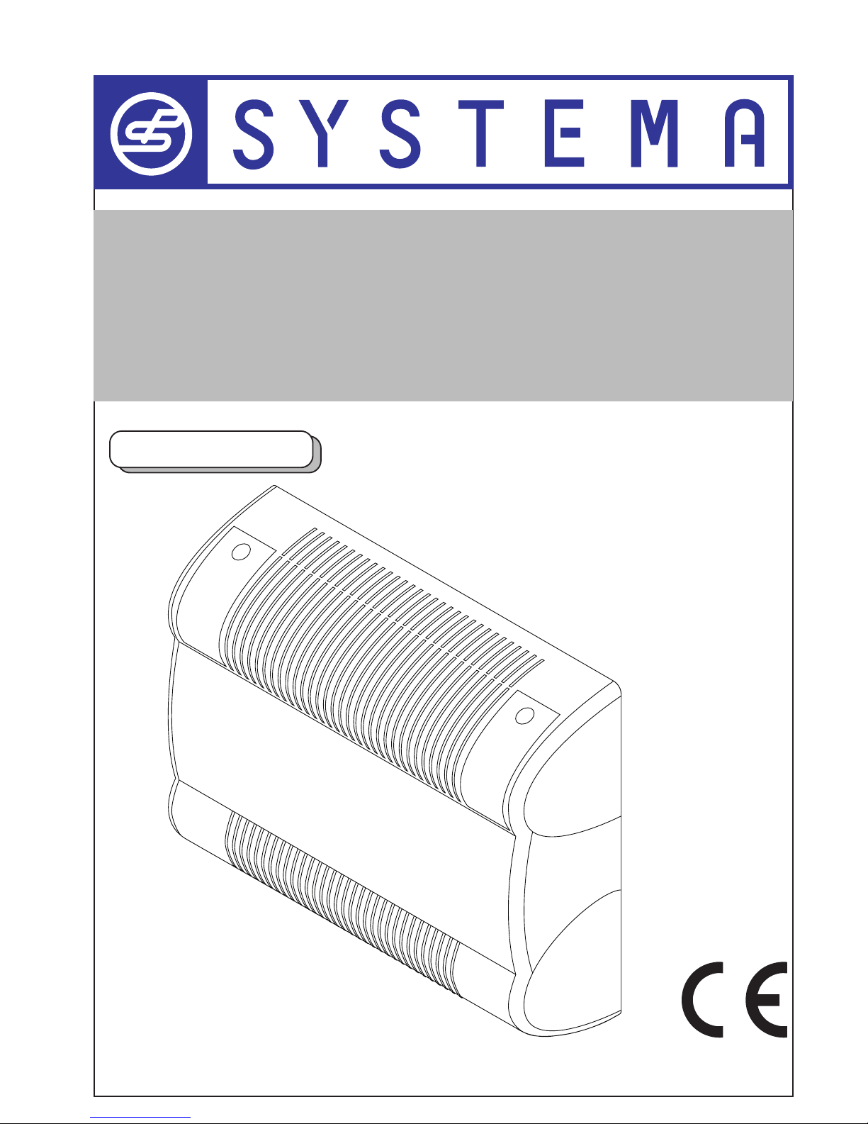
INSTRUCTION MANUAL
“INSTALLATION, USE AND MAINTENANCE”
GREAT BRITAIN
AIRTIGHT GAS CONVECTORS
Pilot flame thermocouple series, natural balanced mod.K21, K28, K40, K55
Ventilated pilot flame thermocouple series, natural balanced mod.K28V, K40V, K55V
Electronic series, natural balanced mod.K21E, K28E,
K40E, K55E
Ventilated electronic series, natural balanced mod.K28VE, K40VE, K55VE
Ventilated/forced circulation series mod.K21FE, K28FE, K40FE,
K55FE
Page 2
2
Rev. 12GB0712
SYSTEMA S.p.A.
AIRTIGHT GAS CONVECTORS
IMPORTANT: Read this manual carefully before starting up the system. In order to improve the product,
Systema reserves the right to modify the content without prior notice.
Via San Martino 17/23
S. GIUSTINA IN COLLE (PD)
loc. Fratte Fontane Bianche
PADOVA - ITALY
Tel 0039 0499355663
(8 linee r.a.)
Fax 0039 0499355699
E-mail: systema@systema.it
technical informations
http://www.systema.it
commercial informations
Page 3

3
Rev. 12GB0712
SYSTEMA S.p.A.
AIRTIGHT GAS CONVECTORS
1 GENERAL RULES . . . . . . . . . . . . . . . . . . . . . . . . . . . . . . . . . . . . . . . . . . . .5
2 GENERAL TECHNICAL CHARACTERISTICS . . . . . . . . . . . . . . . . . . . . . .5
2.1 Device classification . . . . . . . . . . . . . . . . . . . . . . . . . . . . . . . . . . . . . . . . . . . . . . . . . .5
2.2 Packing list and check on incoming material . . . . . . . . . . . . . . . . . . . . . . . . . . . . . .5
2.3 Description and operational characteristics . . . . . . . . . . . . . . . . . . . . . . . . . . . . . . .6
2.4 Principal elements of the control and safety systems . . . . . . . . . . . . . . . . . . . . . . .6
2.5 Pilot flame series technical characteristics . . . . . . . . . . . . . . . . . . . . . . . . . . . . . . . .8
2.6 Electronic series technical characteristics . . . . . . . . . . . . . . . . . . . . . . . . . . . . . . . . .9
2.7 Overall dimensions . . . . . . . . . . . . . . . . . . . . . . . . . . . . . . . . . . . . . . . . . . . . . . . . . . . .10
2.8 Exploded view of convector with parts list . . . . . . . . . . . . . . . . . . . . . . . . . . . . . . . . .11
2.9 Device wiring diagram . . . . . . . . . . . . . . . . . . . . . . . . . . . . . . . . . . . . . . . . . . . . . . . . . .16
3 INSTRUCTIONS FOR INSTALLERS . . . . . . . . . . . . . . . . . . . . . . . . . . . . . .20
3.1 Technical Reference Standards and Legislation . . . . . . . . . . . . . . . . . . . . . . . . . . . .20
3.2 Places of installation and safety distances . . . . . . . . . . . . . . . . . . . . . . . . . . . . . . . .20
3.3 Device installation . . . . . . . . . . . . . . . . . . . . . . . . . . . . . . . . . . . . . . . . . . . . . . . . . . . .21
3.4 Gas line connection . . . . . . . . . . . . . . . . . . . . . . . . . . . . . . . . . . . . . . . . . . . . . . . . . . .25
3.5 Transformations for various types of gas supplies for pilot flame-type devices (Mod.
K21, K28, K40, K55, K28V, K40V, K55V) . . . . . . . . . . . . . . . . . . . . . . . . . . . . . . . . . . .26
3.7 Transformations for various types of gas supplies for electronic devices (Mod. K21E,
K28E, K40E, K55E, K28VE, K40VE, K55VE, K21FE, K28FE, K40FE, K55FE) . . . . .27
3.8 Electrical connections from the control panels to the devices . . . . . . . . . . . . . . . .28
3.9 Starting and operation of pilot flame devices (Mod. K21, K28, K40, K55, K28V, K40V,
K55V) . . . . . . . . . . . . . . . . . . . . . . . . . . . . . . . . . . . . . . . . . . . . . . . . . . . . . . . . . . . . . . .28
3.10 Starting and operation of electronic devices (Mod. K21E, K28E, K40E, K55E, K28VE,
K40VE, K55VE, K21FE, K28FE, K40FE, K55FE) . . . . . . . . . . . . . . . . . . . . . . . . . . . . .28
3.11 Utilization of the daily programmer (optional) . . . . . . . . . . . . . . . . . . . . . . . . . . . . . .29
3.12 Utilization of the weekly programmer (optional) . . . . . . . . . . . . . . . . . . . . . . . . . . . .29
3.13 Malfunctions and solutions for pilot flame devices (Mod. K21, K28, K40, K55, K28V,
K40V, K55V) . . . . . . . . . . . . . . . . . . . . . . . . . . . . . . . . . . . . . . . . . . . . . . . . . . . . . . . . . .30
3.14 Malfunctions and solutions for electronic devices (Mod. K21E, K28E, K40E, K55E,
K28VE, K40VE, K55VE, K21FE, K28FE, K40FE, K55FE) . . . . . . . . . . . . . . . . . . . . . .31
4 INSTRUCTIONS FOR THE USER . . . . . . . . . . . . . . . . . . . . . . . . . . . . . . .32
4.1 General rules . . . . . . . . . . . . . . . . . . . . . . . . . . . . . . . . . . . . . . . . . . . . . . . . . . . . . . . . .32
4.2 Warranty . . . . . . . . . . . . . . . . . . . . . . . . . . . . . . . . . . . . . . . . . . . . . . . . . . . . . . . . . . . . .32
4.2.1 Object and duration of the guarantee . . . . . . . . . . . . . . . . . . . . . . . . . . . . . . . . . . . . . . . . . . . . . . . . . . . .32
4.2.2 Exclusions from the guarantee . . . . . . . . . . . . . . . . . . . . . . . . . . . . . . . . . . . . . . . . . . . . . . . . . . . . . . . . .32
4.2.3 Competence . . . . . . . . . . . . . . . . . . . . . . . . . . . . . . . . . . . . . . . . . . . . . . . . . . . . . . . . . . . . . . . . . . . . . . .33
4.2.4 Operativity and effectiveness of the guarantee . . . . . . . . . . . . . . . . . . . . . . . . . . . . . . . . . . . . . . . . . . . .33
Page 4

4
Rev. 12GB0712
SYSTEMA S.p.A.
AIRTIGHT GAS CONVECTORS
4.2.5 Responsibility . . . . . . . . . . . . . . . . . . . . . . . . . . . . . . . . . . . . . . . . . . . . . . . . . . . . . . . . . . . . . . . . . . . . . .33
4.2.6 Legal disputes - Territorial competence and rights of the parties . . . . . . . . . . . . . . . . . . . . . . . . . . . . . .33
5 PUTTING THE DEVICE OUT OF USE . . . . . . . . . . . . . . . . . . . . . . . . . . . . .33
6 SCRAPPING . . . . . . . . . . . . . . . . . . . . . . . . . . . . . . . . . . . . . . . . . . . . . . . . .33
7 CE CONFORMITY CERTIFICATE . . . . . . . . . . . . . . . . . . . . . . . . . . . . . . . .35
Page 5

5
Rev. 12GB0712
SYSTEMA S.p.A.
AIRTIGHT GAS CONVECTORS
1 GENERAL RULES
This Manual is an integral and essential part of this device and must be carefully stored in its vicinity for purposes of rapid consultation.
Read the instructions and warnings provided herein
carefully because they provide important information
regarding safety, installation, use and maintenance.
Installation must be performed exclusively by qualified
professional personnel in complete respect of the safety
regulations in force. The Manufacturer declines all liability for damages caused by the erroneous installation or
incorrect and/or inappropriate use of the device.
Keep all potentially dangerous packaging elements
(nylon, polystyrene foam, wood, staples, etc.) far from
the reach of children.
The device must be started for the first time by qualified
personnel only.
Immediately switch off the device whenever it stops
and/or malfunctions. All repairs must be performed by
qualified personnel using original spare parts only.
Failure to observe the above can compromise operational safety.
Scrupulously respect the indications provided by the
Manufacture to guarantee satisfactory operation.
Never leave clothes, paper or other objects that might
obstruct the passage of hot air from the slots on top of
the radiator.
Delicate surfaces such as curtains, furniture, and wooden or plastic chairs must be kept at a minimum distance of 30 cm from the device.
Provide extra protection against the risk of burning by
contact of children, the elderly or disabled with the hot
surfaces of the shell wherever necessary. Such additional protection must not obstruct the passage of hot air
and the irradiation of heat from the front panel.
2 GENERAL TECHNICAL CHARACTERISTICS
2.1 Device classification
Device type: Type C11 (natural draught) and C13 (forced draught) depending on the flue gas suction and
expulsion system used.
Device output class: 1
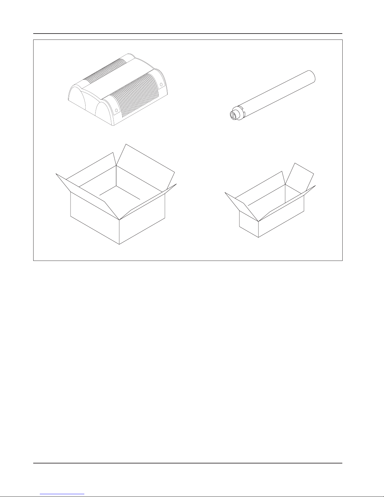
2.2 Packing list and check on
incoming material
a) The device is delivered complete with all its parts in
a box that also contains a set of wall attachment
screws.
b) The air/flue gas terminals and the grille are packed
separately.
Page 6
6
Rev. 12GB0712
SYSTEMA S.p.A.
AIRTIGHT GAS CONVECTORS
CONVECTOR FLUE GAS-AIR KIT
Draw 1 Package contents
2.3 Description and operational
characteristics
The airtight gas convector radiator is composed of a
combustion chamber for the combustion of a gaseous
component (methane or LPG) in airtight cast iron divided into two half-shells that can be opened for cleaning
and the inspection of the burner. The working temperature of the external surface of the combustion chamber
as fanned by the natural convection movement of the
surrounding air or the forced circulation of the fans is
usually reached in a few minutes.
The device functions automatically, and is equipped with
the appropriate systems for safety, control, mixing, combustion, starting, the suction of combustion air and flue
gas expulsion.
The combustion air suction and flue gas expulsion
systems must be mandatorily connected directly to the
building’s exterior (C-type devices) and therefore there
is no contact between the combustion chamber and the
building’s interior. This guarantees the maximum safety
and permits the installation of the device indoors in complete respect of the standards in force.
2.4 Principal elements of the control and safety systems
a) Electric control unit for the Electronic series
models: this can be of two types depending on the
convector model involved (forced or naturally
balanced circulation). After receiving the electric
signal from the room thermostat, the control unit
runs a normal check on the pressure-switch when
forced convectors are being controlled (if this check
is not positive, the control unit does not grant triggering). The control unit then gives the signal for
the performance of the pre-starting lubrication of
the combustion chamber (>4 lubrications) and then
the signal for spark ignition and starting by opening
the gas solenoid valve. If no flame is detected (by
the ionization probe) within the established safety
time, the device goes into lock-out. In order to reset
after lock-out, switch off the bipolar switch with the
orange l.e.d. and then switch it back on again.
Page 7

7
Rev. 12GB0712
SYSTEMA S.p.A.
AIRTIGHT GAS CONVECTORS
CONTROL UNIT TECHNICAL CHARACTERISTICS
Power supply voltage . . . . . . . . . . . . . . . . . . . . . . . . . . . . . . . . . . . . . . . . . . . .220/240 V 50/60Hz
Work temperature . . . . . . . . . . . . . . . . . . . . . . . . . . . . . . . . . . . . . . . . . . . . . .-20 ÷ 60°C
Pre-starting lubrication time . . . . . . . . . . . . . . . . . . . . . . . . . . . . . . . . . . . . . . .10 s
Starting safety time . . . . . . . . . . . . . . . . . . . . . . . . . . . . . . . . . . . . . . . . . . . . .max. 5 s
Switch-off safety time . . . . . . . . . . . . . . . . . . . . . . . . . . . . . . . . . . . . . . . . . . . .< 1 s
b) Pilot gas valve: there is only one type of pilot gas
valve for all pilot flame convector models - a multifunctional valve with single control and combined
manual all-or-nothing thermostat control equipped
with thermoelectric flame detection device with
reset inhibition, maximum flowrate pre-selection
device or pressure regulator, minimum flowrate preselection screw, all-or-nothing modulation thermostat, pilot flame output with gas flowrate pre-selection screw, inlet filter and pilot filter, inlet and outlet
pressure taps - lateral gas outlets or gas outlets
from below with RP 3/8 ISO 7 threads. To start,
press the dial and switch on the pilot flame by keeping the dial pressed down for a few seconds. Then
release the dial and check to make sure that the
pilot flame remains on. If the pilot flame has gone
out in the meantime, the reset inhibition device will
prevent the re-starting of the convector until the
established pilot flame detection device safety time
has elapsed.
PILOT GAS VALVE TECHNICAL DATA
Gas connections . . . . . . . . . . . . . . . . . . . . . . . . . . . . . . . . . . . . . . . . . . . . . . .RP 3/8 ISO 7
Max. inlet pressure . . . . . . . . . . . . . . . . . . . . . . . . . . . . . . . . . . . . . . . . . . . . .50 mbar
Pressure setting range . . . . . . . . . . . . . . . . . . . . . . . . . . . . . . . . . . . . . . . . . . .3 ÷ 18 mbar
Room temperature . . . . . . . . . . . . . . . . . . . . . . . . . . . . . . . . . . . . . . . . . . . . . .0° ÷ 80°C
Pressure regulator . . . . . . . . . . . . . . . . . . . . . . . . . . . . . . . . . . . . . . . . . . . . . .CLASS C
Pilot flame detection device . . . . . . . . . . . . . . . . . . . . . . . . . . . . . . . . . . . . . . .Sit series 200 or 290 thermocouple
Starting time . . . . . . . . . . . . . . . . . . . . . . . . . . . . . . . . . . . . . . . . . . . . . . . . . . .< 10 s
Switch off time . . . . . . . . . . . . . . . . . . . . . . . . . . . . . . . . . . . . . . . . . . . . . . . . .< 60 s
c) Gas solenoid valve: for all electronic series and for-
ced ventilation convectors, multifunctional and multigas with a double safety solenoid valve (connected in series) in Class A and a built-in rectifier bridge. The aluminum body holds the inlet gas connec-
tions - threaded G 3/8" outlet with respective pressure taps. Equipped with pressure regulator to be
adjusted only by qualified technicians, the only
maintenance operation possible on the valve.
GAS VALVE TECHNICAL DATA
Power supply voltage . . . . . . . . . . . . . . . . . . . . . . . . . . . . . . . . . . . . . . . . . . . .220/240 VAC 50/60 Hz
Electrical protection rating . . . . . . . . . . . . . . . . . . . . . . . . . . . . . . . . . . . . . . . .IP40
Closing time . . . . . . . . . . . . . . . . . . . . . . . . . . . . . . . . . . . . . . . . . . . . . . . . . . .01 s
Work temperature . . . . . . . . . . . . . . . . . . . . . . . . . . . . . . . . . . . . . . . . . . . . . .-20 ÷ +60°C
Max. inlet pressure . . . . . . . . . . . . . . . . . . . . . . . . . . . . . . . . . . . . . . . . . . . . .100 mbar
Work pressure range . . . . . . . . . . . . . . . . . . . . . . . . . . . . . . . . . . . . . . . . . . . .0 ÷ 100 mb
Gas flow rate . . . . . . . . . . . . . . . . . . . . . . . . . . . . . . . . . . . . . . . . . . . . . . . . . .1,5 m3/h (Natural gas DP = 2,5 mb)
d) Air suction unit: this serves to suck the air from the
outside and inject it into the combustion chamber
with the consequent expulsion of the flue gases
outwards through the appropriate flue gas duct.
SUCTION UNIT MOTOR RATING PLATE DATA
Electrical power supply . . . . . . . . . . . . . . . . . . . . . . . . . . . . . . . . . . . . . . . . . .230 VAC 50 Hz
Insulation . . . . . . . . . . . . . . . . . . . . . . . . . . . . . . . . . . . . . . . . . . . . . . . . . . . . .CLASS H
Motor pack . . . . . . . . . . . . . . . . . . . . . . . . . . . . . . . . . . . . . . . . . . . . . . . . . . . .da 30 mm
Power . . . . . . . . . . . . . . . . . . . . . . . . . . . . . . . . . . . . . . . . . . . . . . . . . . . . . . . .20 WATT
Page 8
8
Rev. 12GB0712
SYSTEMA S.p.A.
AIRTIGHT GAS CONVECTORS
2.5 Pilot flame series technical
characteristics
THERMOSTAT CHARACTERISTICS
Electrical power supply . . . . . . . . . . . . . . . . . . . . . . . . . . . . . . . . . . . . . . . . . .240 V 20 A
Work range . . . . . . . . . . . . . . . . . . . . . . . . . . . . . . . . . . . . . . . . . . . . . . . . . . .6° ÷ 30°C
Max. bulb temperature . . . . . . . . . . . . . . . . . . . . . . . . . . . . . . . . . . . . . . . . . . .42°C
Sensor . . . . . . . . . . . . . . . . . . . . . . . . . . . . . . . . . . . . . . . . . . . . . . . . . . . . . . .copper
Bulb . . . . . . . . . . . . . . . . . . . . . . . . . . . . . . . . . . . . . . . . . . . . . . . . . . . . . . . . .copper
f) Daily or weekly programmer (only on request): this
serves to program the device’s daily and weekly
operation cycles and is positioned on the control
e) Adjustment thermostat: this is a sensor-type ther-
mostat that permits the temperature to be adjusted
as required by the user for a comfortable room tem-
perature, and also permits the control of the starting
and switching off of the device from the control unit.
panel for access by the user for adjustment purposes.
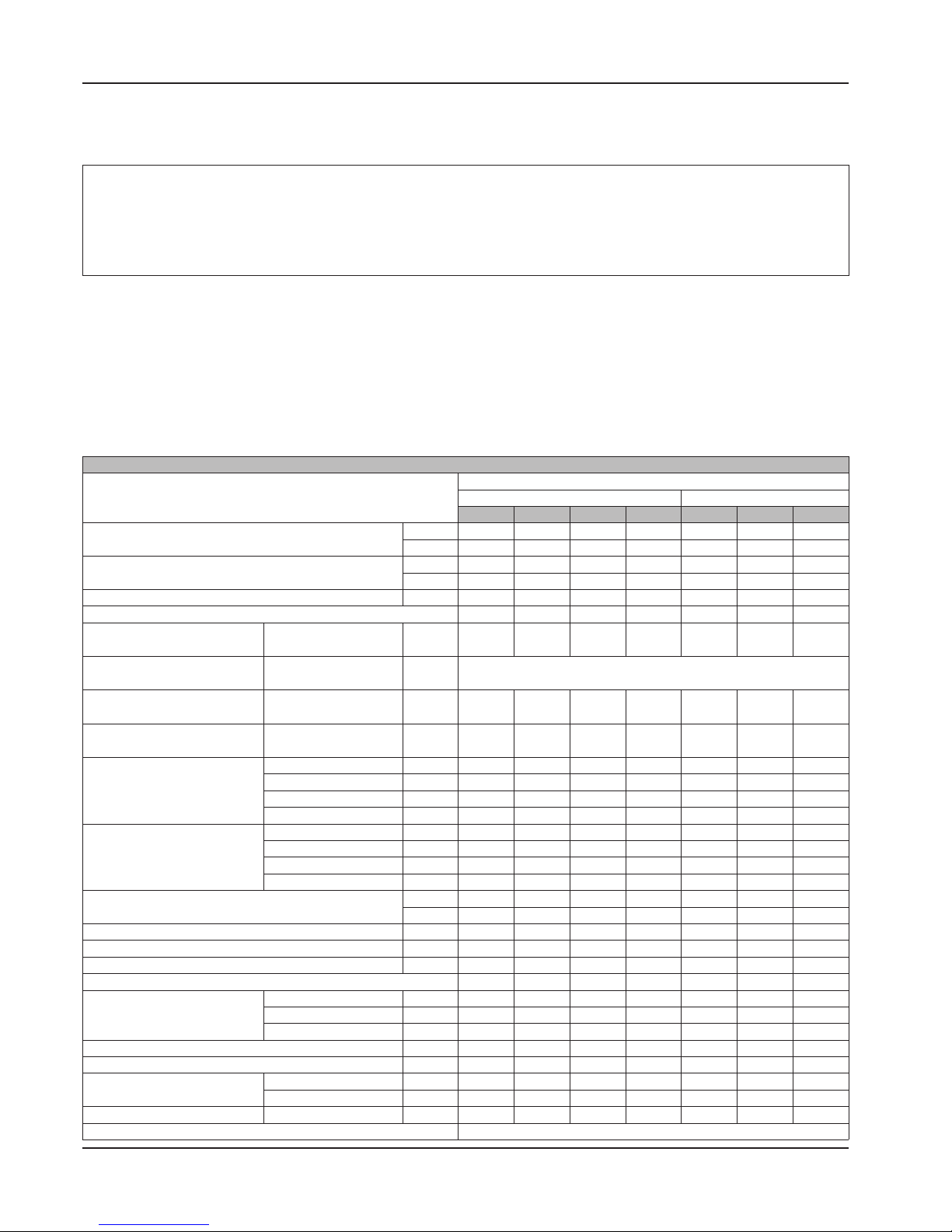
TECHNICAL SPECIFICATIONS OF AIRTIGHT GAS CONVECTORS
PILOT FLAME THERMOCOUPLE SERIES MODELS
NON-VENTILATED
VENTILATED
K21 K28 K40 K55 K28V K40V K55V
RATED HEAT FLOW
kW 2 2,5 4 4,6 2,5 4 4,6
kcal/h 1720 2150 3440 3960 2150 3440 3960
WORKING HEAT OUTPUT
kW 1,8 2,2 3,5 4,1 2,2 3,6 4,1
kcal/h 1550 1900 3010 3530 1900 3100 3530
COMBUSTION EFFICIENCY
% 90,0 87,0 87,3 87,5 87,5 88,0 88,0
CATEGORY EFFICIENCY
1 1 1 1 1 1 1
INJECTOR PRESSURE
(power supply=20mbar)
Methane G20
mbar 13,2 12,0 12,5 14,0 12,0 12,5 14,0
INJECTOR PRESSURE
(power supply=25mbar)
Gas L - G25
mbar
-
INJECTOR PRESSURE
(power supply=29mbar)
GPL Butane - G30
mbar 28.9 28.8 28.9 29.0 28.8 28.9 29.0
INJECTOR PRESSURE
(power supply=37mbar)
GPL Propane - G31
mbar 36.6 36.8 36.7 36.5 36.6 36.7 36.5
BURNER INJECTOR DIAMETER
Methane G20
mm 1,25 1,45 1,90 1,90 1,45 1,90 1,90
Gas L - G25
mm 1.25 1.45 1.90 1.90 1.45 1.90 1.90
GPL Butane - G30
mm 0.75 0.85 1.05 1.10 0.85 1.05 1.10
GPL Propane - G31
mm 0,75 0,85 1,05 1,10 0,85 1,05 1,10
MAX FUEL
CONSUMPTION
(0°C - 1013 mbar)
Methane G20
m
3
0,21 0,26 0,42 0,49 0,26 0,42 0,49
Gas L - G25
m
3
0.25 0.31 0.49 0.57 0.31 0.49 0.57
GPL Butane - G30
kg/h 0.158 0.197 0.315 0.363 0.197 0.315 0.363
GPL Propane - G31
kg/h 0,155 0,194 0,311 0,357 0,194 0,311 0,357
ELECTRICAL POWER SUPPLY
V -- -- -- -- 230 230 230
Hz -- -- -- -- 50 50 50
ELECTRICAL POWER (absorbed)
W -- -- -- -- 25 30 30
TREATED AMBIENT AIR FLOW
m3/h -- -- -- -- 150 240 270
HEATED AMBIENT VOLUME
m
3
36 44 70 82 48 78 88
FAN SPEED NUMBER
-- -- -- -- 2 2 2
OVERALL DIMENSIONS
Width
mm 420 420 560 560 420 560 560
Height
mm 615 615 615 615 615 615 615
Depth
mm 225 225 225 225 225 225 225
WEIGHT
kg 31 31 45 45 32 46 46
GAS FITTING DIAMETER
inc. (”) 1/2"- M 1/2"- M 1/2"- M 1/2"- M 1/2"- M 1/2"- M 1/2"- M
AIR-FUME COAXIAL
PIPE DIAMETERS
Air
mm 120 120 160 160 120 160 160
Fumes
mm 90 90 90 90 90 90 90
AIR-FUME MAX LENGHT
coaxial pipes
mm 500 500 500 500 500 500 500
TYPE OF EQUIPMENT
C11
Page 9

9
Rev. 12GB0712
SYSTEMA S.p.A.
AIRTIGHT GAS CONVECTORS
2.6 Electronic series technical
characteristics
(*) N.B. One meter of length must be removed for every elbow used in forced ventilation electronic models (FE).
Categories
AT . . . . . . . . . . . . . . . . . . . . . . . . . .II
2H3B/P
DE . . . . . . . . . . . . . . . . . . . . . . . . . .II
2ELL3B/P
FI . . . . . . . . . . . . . . . . . . . . . . . . . . .II
2H3B/P
GR . . . . . . . . . . . . . . . . . . . . . . . . . .II
2H3P
IT . . . . . . . . . . . . . . . . . . . . . . . . . . .II
2H3+
NO . . . . . . . . . . . . . . . . . . . . . . . . . .II
2H3B/P
BE . . . . . . . . . . . . . . . . . . . . . . . . . . .I
2E+
/ I
3+
DK . . . . . . . . . . . . . . . . . . . . . . . . . .II
2H3B/P
FR . . . . . . . . . . . . . . . . . . . . . . . . . .II
2E+3+
IE . . . . . . . . . . . . . . . . . . . . . . . . . . .II
2H3P
LU . . . . . . . . . . . . . . . . . . . . . . . . . .II
2E3P
PT . . . . . . . . . . . . . . . . . . . . . . . . . .II
2H3P
CH . . . . . . . . . . . . . . . . . . . . . . . . . .II
2H3B/P
ES . . . . . . . . . . . . . . . . . . . . . . . . . .II
2H3P
GB . . . . . . . . . . . . . . . . . . . . . . . . . .II
2H3P
NL . . . . . . . . . . . . . . . . . . . . . . . . . .II
2L3B/P
SE . . . . . . . . . . . . . . . . . . . . . . . . . .II
2H3B/P
IS . . . . . . . . . . . . . . . . . . . . . . . . . . .I
3B/P
TECHNICAL SPECIFICATIONS OF AIRTIGHT GAS CONVECTORS
ELECTRONONIC SERIES MODELS
NON-VENTILATED VENTILATED NON-VENTILATED
K21E K28E K40E K55E K28VE K40VE K55VE K21FE K28FE K40FE K55FE
RATED HEAT FLOW
kW
2 2,5 4 4,6 2,5 4 4,6 2,4 3 4,3 5,3
kcal/h
1720 2150 3440 3960 2150 3440 3960 2070 2580 3700 4560
WORKING HEAT OUTPUT
kW
1,8 2,3 3,6 4,1 2,3 3,6 4,1 2,2 2,7 3,8 4,6
kcal/h
1550 1980 3100 3530 1980 3100 3530 1900 2330 3270 3960
COMBUSTION EFFICIENCY
%
89,8 90,0 88,0 88,0 90,0 88,0 88,0 88,5 88,0 88,3 85,0
CATEGORY EFFICIENCY
1 1 1 1 1 1 1 1 1 1 1
INJECTOR PRESSURE
(power supply=20mbar)
Methane G20
mbar
14,0 12,0 11,0 13,5 12,0 11,0 13,5 12,0 13,0 12,0 12,0
INJECTOR PRESSURE
(power supply=25mbar)
Gas L - G25
mbar
13,5 12,5 11,0 10,0 12,5 11,0 10,0 12,0 13,0 12,0 12,0
INJECTOR PRESSURE
(power supply=29mbar)
GPL Butane - G30
mbar
28,5 28,5 28,0 29,0 28,5 28,0 29,0 28,5 28,5 28,4 28,6
INJECTOR PRESSURE
(power supply=37mbar)
GPL Propane - G31
mbar
36,5 37,0 35,5 37,0 37,0 35,5 37,0 36,5 36,5 36,4 36,4
BURNER INJECTOR DIAMETER
Methane G20
mm
0,75 0,85 1 1,1 0,85 1 1,1 0,82 0,9 1,05 1,15
Gas L - G25
mm
1,5 1,6 2,1 2,3 1,6 2,1 2,3 1,5 1,7 2,1 2,4
GPL Butane - G30
mm
0,75 0,85 1 1,1 0,85 1 1,1 0,82 0,9 1,05 1,15
GPL Propane - G31
mm
1,25 1,45 1,9 1,9 1,45 1,9 1,9 1,4 1,6 1,9 2,1
MAX FUEL
CONSUMPTION
(0°C - 1013 mbar)
Methane G20
m
3
0,21 0,26 0,42 0,49 0,26 0,42 0,49 0,25 0,32 0,46 0,56
Gas L - G25
m
3
0,25 0,31 0,49 0,57 0,31 0,49 0,57 0,30 0,37 0,53 0,65
GPL Butane - G30
kg/h
0,158 0,197 0,315 0,363 0,197 0,315 0,363 0,189 0,237 0,339 0,418
GPL Propane - G31
kg/h
0,155 0,194 0,311 0,357 0,194 0,311 0,357 0,186 0,233 0,334 0,412
ELECTRICAL POWER SUPPLY
V
230 230 230 230 230 230 230 230 230 230 230
Hz
50 50 50 50 50 50 50 50 50 50 50
ELECTRICAL POWER (absorbed)
W
20 20 20 20 45 65 65 65 65 85 85
TREATED AMBIENT AIR FLOW
m3/h
-- -- -- -- 150 240 270 150 180 260 310
HEATED AMBIENT VOLUME
m
3
36 46 72 82 50 78 88 48 58 84 102
FAN SPEED NUMBER
-- -- -- -- 2 2 2 2 2 2 2
OVERALL DIMENSIONS
Width
mm
420 420 560 560 420 560 560 560 560 730 730
Height
mm
615 615 615 615 615 615 615 615 615 615 615
Depth
mm
225 225 225 225 225 225 225 225 225 225 225
WEIGHT
kg
32 32 46 46 32 46 46 32 33 52 52
GAS FITTING DIAMETER
inc. (”)
3/8"- F 3/8"- F 3/8"- F 3/8"- F 3/8"- F 3/8"- F 3/8"- F 3/8"- F 3/8"- F 3/8"- F 3/8"- F
AIR-FUME COAXIAL PIPE
DIAMETERS
Air
mm
120 120 160 160 120 160 160 60 60 60 60
Fumes
mm
90 90 90 90 90 90 90 38 38 38 38
AIR-FUME MAX LENGHT coaxial pipes
mm
500 500 500 500 500 500 500 5000 5000 5000 3000
TYPE OF EQUIPMENT C11 C13
Page 10
10
Rev. 12GB0712
SYSTEMA S.p.A.
AIRTIGHT GAS CONVECTORS
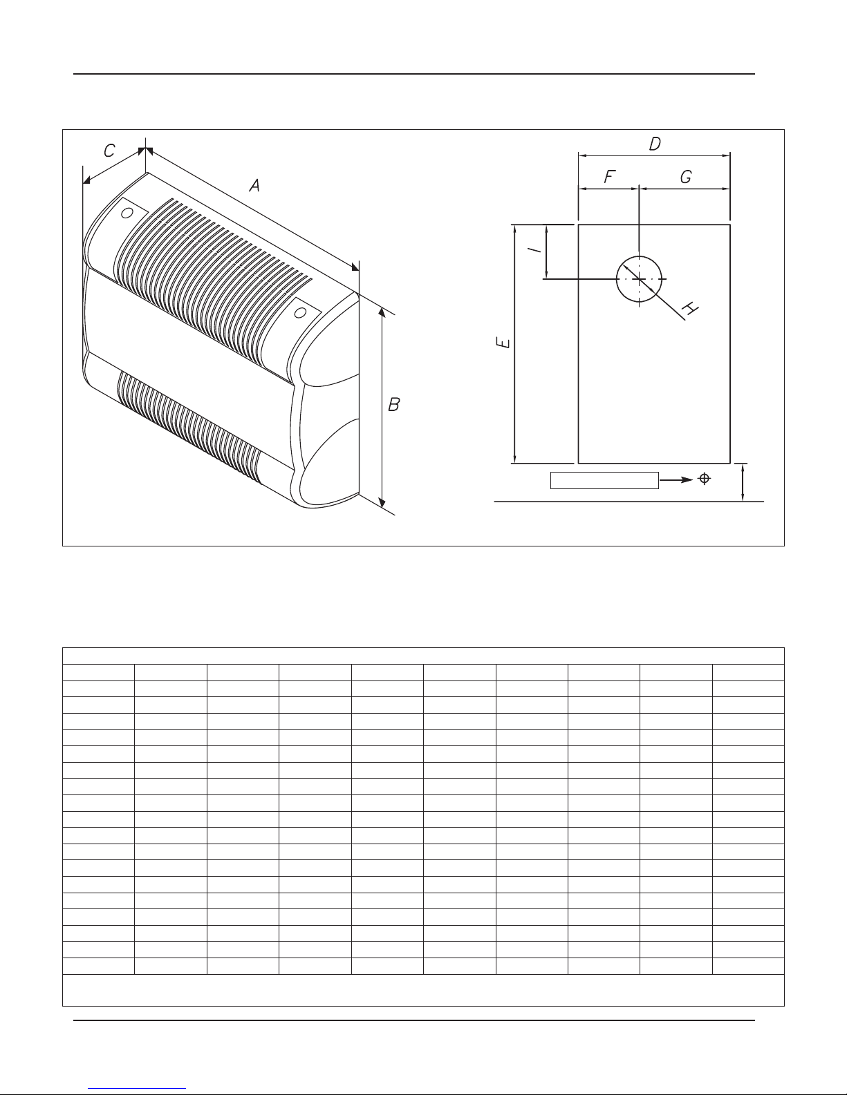
Draw2
2.7 Overall dimensions
GAS CONNECTION
10 cm
min.
ATTENTION: the KING gas convector must be installed at 10 cm minimum distance from the ground; it
is necessary to forsee the space for the gas interception. The hole for the gas pipe has to be provided
under the appliance, between the appliance and the ground, according to the gas inlet of the appliance
itself.
CONVECTOR OVERALL DIMENSIONS AND ASSEMBLY FRAME
MODELS A B C D E F G H I
K21
440 624 225 385 611 173 212 125 116
K28
440 624 225 385 611 173 212 125 116
K40
600 624 225 549 611 264 285 160 124
K55
600 624 225 549 611 264 285 160 124
K28V
440 624 225 385 611 173 212 125 117
K40V
600 624 225 549 611 264 285 160 124
K55V
600 624 225 549 611 264 285 160 124
K21E
440 624 225 385 611 173 212 125 117
K28E
440 624 225 385 611 173 212 125 117
K40E
600 624 225 549 611 264 285 160 124
K55E
600 624 225 549 611 264 285 160 124
K28VE
440 624 225 385 611 173 212 125 117
K40VE
600 624 225 549 611 264 285 160 124
K55VE
600 624 225 549 611 264 285 160 124
K21FE
585 616 225 535 612 305 230 60 108
K28FE
585 616 225 535 612 305 230 60 108
K40FE
745 616 225 689 612 399 290 60 108
K55FE
745 616 225 689 612 399 290 60 108
The data provided above are purely indicative. The Manufacturer reserves the right to perform modifications without notice.
Page 11

11
Rev. 12GB0712
SYSTEMA S.p.A.
AIRTIGHT GAS CONVECTORS
2.8 Exploded view of convector
with parts list
Draw 3 Exploded view of Model K21, K28, K40, K55 generator
PILOT FLAME TYPE THERMOCOUPLE SERIES CONVECTOR (Ref. Draw 3)
POS. Q. ITEM
K21 K28 K40 K55
CODE CODE CODE CODE
1 1 PAIR OF COAXIAL TUBES 02ACKT0808 02ACKT0808 02ACKT0810 02ACKT0810
2 1 AIR BOX 02CNSA0378 02CNSA0378 02CNSA0379 02CNSA0379
3 1 EUROSIT PILOT FLAME VALVE 02CNVE0679 02CNVE0679 02CNVE0679 02CNVE0679
4 1 REAR CAST IRON CASTING 02CNFU0201 02CNFU0201 02CNFU0203 02CNFU0203
5 1 BURNER 02CNBR0050 02CNBR0050 02CNBR0052 02CNBR0051
6 1 FRONT CAST IRON CASTING 02CNFU0200 02CNFU0200 02CNFU0202 02CNFU0202
7 1 SHELL 02MACO0028 02MACO0028 02MACO0029 02MACO0029
Page 12

12
Rev. 12GB0712
SYSTEMA S.p.A.
AIRTIGHT GAS CONVECTORS
Draw 4 Exploded view of Model K28V, K40V, K55V generator
VENTILATED PILOT FLAME THERMOCOUPLE SERIES CONVECTORS (Ref. Draw 4)
POS. Q. ITEM
K28V K40V K55V
CODE CODE CODE
1 1 PAIR OF COAXIAL TUBES 02ACKT0808 02ACKT0810 02ACKT0810
2 1 FAN TRIGGERING THERMOSTAT 02CETR0470 02CETR0470 02CETR0470
3 1 AIR BOX 02CNSA0378 02CNSA0379 02CNSA0379
4 1 EUROSIT PILOT FLAME VALVE 02CNVE0679 02CNVE0679 02CNVE0679
5 1 MOLVENO I-II SWITCH 02CEDE0234 02CEDE0234 02CEDE0234
6 1 TANGENTIAL FAN 02CEVT0622 02CEVT0623 02CEVT0623
7 1 REAR CAST IRON CASTING 02CNFU0201 02CNFU0203 02CNFU0203
8 1 BURNER 02CNBR0050 02CNBR0052 02CNBR0051
9 1 FRONT CAST IRON CASTING 02CNFU0200 02CNFU0202 02CNFU0202
10 1 SHELL 02MACO0028 02MACO0029 02MACO0029
Page 13

13
Rev. 12GB0712
SYSTEMA S.p.A.
AIRTIGHT GAS CONVECTORS
Draw 5 Exploded view of Model K21E, K28E, K40E, K55E generator
ELECTRONIC SERIES CONVECTORS (Ref. Draw 5)
POS. Q. ITEM
K21E K28E K40E K55E
CODICE CODICE CODICE CODICE
1 1 PAIR OF COAXIAL TUBES 02ACKT0808 02ACKT0808 02ACKT0810 02ACKT0810
2 1 LIMIT THERMOSTAT 02CETR0471 02CETR0471 02CETR0471 02CETR0471
3 1 AIR BOX 02CNSA0378 02CNSA0378 02CNSA0379 02CNSA0379
4 1
BRAHMA CM11F DEVICE 02CEAP2701 02CEAP2701 02CEAP2701 02CEAP2701
IMIT AC02 DEVICE 02CEAP1028 02CEAP1028 02CEAP1028 02CEAP1028
5 1 ELECTRIC CONTROL PANEL KING E 02CEQU0345 02CEQU0345 02CEQU0345 02CEQU0345
6 1
WHITE ROGERS ELECTRONIC VALVE 02CEEC0164 02CEEC0164 02CEEC0164 02CEEC0164
SIT 850 MICRO ELECTRONIC VALVE 02CEEL0166 02CEEL0166 02CEEL0166 02CEEL0166
7 1 REAR CAST IRON CASTING 02CNFU0201 02CNFU0201 02CNFU0203 02CNFU0203
8 1 BURNER 02CNBR0058 02CNBR0050 02CNBR0051 02CNBR0051
9 1 FRONT CAST IRON CASTING 02CNFU0200 02CNFU0200 02CNFU0202 02CNFU0202
10 1 SHELL 02MACO0028 02MACO0028 02MACO0029 02MACO0029
Page 14

14
Rev. 12GB0712
SYSTEMA S.p.A.
AIRTIGHT GAS CONVECTORS
Draw 6 Exploded view of Model 28VE, K40VE, K55VE generator
VENTILATED ELECTRONIC SERIES CONVECTORS (Ref. Draw 6)
POS. Q. ITEM
K28VE K40VE K55VE
CODE CODE CODE
1 1 PAIR OF COAXIAL TUBES 02ACKT0808 02ACKT0810 02ACKT0810
2 1 LIMIT THERMOSTAT 02CETR0471 02CETR0471 02CETR0471
3 1 FAN TRIGGERING THERMOSTAT 02CETR0470 02CETR0470 02CETR0470
4 1 AIR BOX 02CNSA0378 02CNSA0379 02CNSA0379
5 1
BRAHMA CM11F DEVICE 02CEAP2701 02CEAP2701 02CEAP2701
IMIT AC02 DEVICE 02CEAP1028 02CEAP1028 02CEAP1028
6 1 ELECTRIC CONTROL PANEL KING VE 02CEQU0344 02CEQU0344 02CEQU0344
7 1 TANGENTIAL FAN 02CEVT0622 02CEVT0623 02CEVT0623
8 1
WHITE ROGERS ELECTRONIC VALVE 02CEEC0164 02CEEC0164 02CEEC0164
SIT 850 MICRO ELECTRONIC VALVE 02CEEL0166 02CEEL0166 02CEEL0166
9 1 REAR CAST IRON CASTING 02CNFU0201 02CNFU0203 02CNFU0203
10 1 BURNER 02CNBR0050 02CNBR0058 02CNBR0058
11 1 FRONT CAST IRON CASTING 02CNFU0200 02CNFU0202 02CNFU0202
12 1 SHELL 02MACO0028 02MACO0029 02MACO0029
Page 15

15
Rev. 12GB0712
SYSTEMA S.p.A.
AIRTIGHT GAS CONVECTORS
31
2
4567
8
9
10
11 12 13 14
Draw 7 Exploded view of Model K21FE, K28FE, K40FE, K50FE generator
VENTILATED/FORCED CIRCULATION SERIES CONVECTORS (Ref. Draw 7)
POS. Q. ITEM
K21FE K28FE K40FE K55FE
CODE CODE CODE CODE
1 1
PAIR OF COAXIAL TUBES
02ACKT0800 02ACKT0800 02ACKT0800 02ACKT0800
2 1
STAINLESS STEEL ANTI-WIND GRILLE FOR
RECESSED WALL MOUNTING
02ACKT0801 02ACKT0801 02ACKT0801 02ACKT0801
3 1
LIMIT THERMOSTAT
02CETR0471 02CETR0471 02CETR0471 02CETR0471
4 1
FAN TRIGGERING THERMOSTAT
02CETR0470 02CETR0470 02CETR0470 02CETR0470
5 1
AIR BOX
02CNSA0376 02CNSA0376 02CNSA0377 02CNSA0377
6 1
IMIT AC02 DEVICE
02CEAP1028 02CEAP1028 02CEAP1028 02CEAP1028
7 1
ELECTRIC CONTROL PANEL KING FE
02CEQU0343 02CEQU0343 02CEQU0343 02CEQU0343
8 1
EV 100 CENTRIFUGAL FAN
02CEAS3002 02CEAS3002 02CEAS3002 02CEAS3002
9 1
TANGENTIAL FAN
02CEVT0622 02CEVT0622 02CEVT0623 02CEVT0623
10 1
WHITE ROGERS ELECTRONIC VALVE
02CEEC0164 02CEEC0164 02CEEC0164 02CEEC0164
SIT 850 MICRO ELECTRONIC VALVE 02CEEL0166 02CEEL0166 02CEEL0166 02CEEL0166
11 1
REAR CAST IRON CASTING
02CNFU0201 02CNFU0201 02CNFU0203 02CNFU0203
12 1
BURNER
02CNBR0050 02CNBR0050 02CNBR0058 02CNBR0058
13 1
FRONT CAST IRON CASTING
02CNFU0200 02CNFU0200 02CNFU0202 02CNFU0202
14 1
SHELL
02MACO0031 02MACO0031 02MACO4055 02MACO4055
Page 16

16
Rev. 12GB0712
SYSTEMA S.p.A.
AIRTIGHT GAS CONVECTORS
2.9 Schema elettrico apparecchi
Series V wiring diagram
Series E wiring diagram
Draw 8
Draw 9
KEY
L Phase wire
N Neutral wire
W
Ground
DB Bipolar switch
TR Regulation thermostat
SB Lock-out light
SF Operation light
EV1 EV2 Electronic valve
ER Detection electrode
E ACC. Starting electrode
CEN
Imit AC02 or Brahma CM11F
electronic valve
TL Work thermostat
KEY
L Phase wire
N Neutral wire
W
Ground
TCV Fan triggering thermostat
DV Speed change gear
VT Tangential fan
Page 17

17
Rev. 12GB0712
SYSTEMA S.p.A.
AIRTIGHT GAS CONVECTORS
Series E with timer wiring diagram
Series VE wiring diagram
Draw 10
Draw 11
KEY
L Phase wire
N Neutral wire
W
Ground
DB Bipolar switch
TR Regulation thermostat
SB Lock-out light
SF Operation light
EV1 EV2 Electronic valve
ER Detection electrode
E ACC. Starting electrode
CEN
Imit AC02 or Brahma CM11F
electronic valve
TL Work thermostat
KEY
L Phase wire
N Neutral wire
W
Ground
DB Bipolar switch
TR Regulation thermostat
TCV Fan triggering thermostat
VT Fan
DV Fan switch
SB Lock-out light
SF Operation light
EV1 EV2 Electronic valve
ER Detection electrode
E ACC. Starting electrode
CEN
Imit AC02 or Brahma CM11F
electronic valve
TL Work thermostat
Page 18

18
Rev. 12GB0712
SYSTEMA S.p.A.
AIRTIGHT GAS CONVECTORS
Series VE with timer wiring diagram
Series FE wiring diagram
Draw 12
Draw 13
KEY
L Phase wire
N Neutral wire
W
Ground
DB Bipolar switch
TR Regulation thermostat
TCV Fan triggering thermostat
VT Fan
DV Fan switch
SB Lock-out light
SF Operation light
EV1 EV2 Electronic valve
ER Detection electrode
E ACC. Starting electrode
CEN
Imit AC02 or Brahma CM11F
electronic valve
TL Work thermostat
KEY
L Phase wire
N Neutral wire
W
Ground
DB Bipolar switch
TR Regulation thermostat
TCV Fan triggering thermostat
VT Fan
DV Fan switch
SB Lock-out light
SF Operation light
EV1 EV2 Electronic valve
ER Detection electrode
E ACC. Starting electrode
CF Fan
CEN Imit AC02 electronic valve
TL Work thermostat
Page 19

19
Rev. 12GB0712
SYSTEMA S.p.A.
AIRTIGHT GAS CONVECTORS
Series FE with timer wiring diagram
Draw 14
KEY
L Phase wire
N Neutral wire
W
Ground
DB Bipolar switch
TR Regulation thermostat
TCV Fan triggering thermostat
VT Fan
DV Fan switch
SB Lock-out light
SF Operation light
EV1 EV2 Electronic valve
ER Detection electrode
E ACC. Starting electrode
CF Fan
CEN Imit AC02 electronic valve
TL Work thermostat
Page 20

20
Rev. 12GB0712
SYSTEMA S.p.A.
AIRTIGHT GAS CONVECTORS
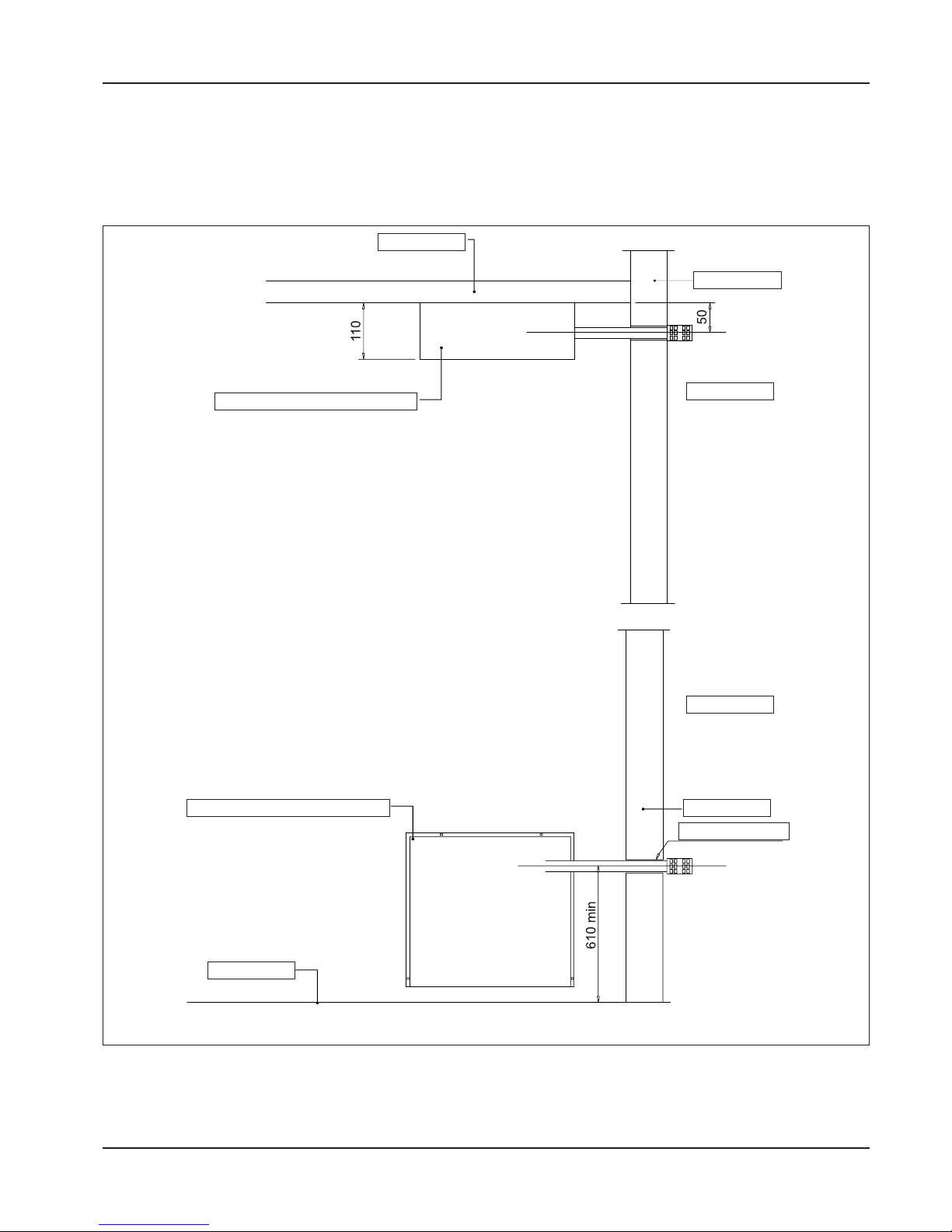
Draw 15
3 INSTRUCTIONS FOR INSTALLERS
3.1 Places of installation and
safety distances
We recommend observing the following rules in order to
obtain the maximum convector output efficiency:
- Position the device while bearing in mind the priority
areas to be heated, the absorption walls (windows,
doors, French windows etc.), and the existence of
shelves and other obstacles that might compromise
the circulation of the hot air released by the radiator
above and the effect of the heat radiated from the
front panel.
- If more than one device must be installed in the
same room, we recommend staggered and opposing positioning in order to provide the entire area
with uniform coverage.
- The devices must never be installed in recessed
niches or positions that do not ensure sufficient
aeration for good operation.
- Install the devices along perimetral walls whenever
possible.
- Observe the following rules to simplify interven-
tions on the radiator or the removal of the shell:
a) the distance of the device from the floor must
never be less than 10 cm.;
b) any shelves installed above the radiator must be
positioned at least 10 cm higher;
c) a minimum distance of 10 cm from the wall must
be respected whenever devices are installed in
recessed niches;
- avoid positioning furnishings above the shell.
Installation must be performed only by qualified professionals in complete respect of the safety regulations in
force. The Manufacturer declines all liability for erroneous installation or the inappropriate or incorrect use of
the device.
Page 21

21
Rev. 12GB0712
SYSTEMA S.p.A.
AIRTIGHT GAS CONVECTORS
8
8613
2
T
Y
6
8
G
3.2 Installation of the natural
balanced appliance.
For the assembling of the appliance, please follow the
instruction given in the following pages:
1) Place the template on the wall and fix it with adhesi-
ve tape at a distance of minimum 10 cm from the
floor perfectly in square (see draw 16). Draw the hole
for the exhaust and, if possible, make it with a 2%
inclination outwards the wall (see draw 17).
2) Place the template in square again and be careful
when centring it with the hole for the exhaust, then
make 4 holes of 8 mm in diameter and insert the supplied inserts (see draw 16).
Draw 17
Draw 16
INTERNAL
GROUND
EXTERNAL
Draw 18
Draw 19
Cutting Pipes exhaust kit natural balanced models
3) When the hole is done, measure the thickness of
the wall (M).
- Cut the suction pipe (8) on the side without rim (see
draw 17) 10mm longer than the thickness of the
wall (M).
- Cut the exhaust pipe (6) 65mm longer than the
thickness of the wall (M) measuring it from the air
intake grid (G) to the end (T) of the pipe, which has
to be inserted in the convector (see draw 18).
Assembling exhaust kit natural balanced models
4) Remove the shell (1) after having unloosing the
fixing screws (2) (see draw 19)
5) Superimpose the gasket on the pipe.
- Fix the suction pipe on the side of the rim (8) with
the 4 self-threading screws supplied (see draw 22).
6) Place the convector with the supplied screws,
wedge the fumes pipe grille (6) in the internal collar
of the air box (3) and fix it on the external wall with
the two supplied inserts.
Page 22

22
Rev. 12GB0712
SYSTEMA S.p.A.
AIRTIGHT GAS CONVECTORS
8
8
6
6
8
6
6
Y
A
4
8
6
1
2
8
Draw 22
Draw 21
3.2.1 Installation of the forced appliance with model grille
For the assembling of the appliance, please follow the
instruction given in the following pages:
1) Place the template on the wall and fix it with adhesi-
ve tape at a distance of minimum 10 cm from the
floor perfectly in square (see draw 20). Draw the hole
for the exhaust and, if possible, make it with a 2%
inclination outwards the wall (see draw 21).
2) Place the template in square again and be careful
when centring it with the hole for the exhaust, then
make 4 holes of 8 mm in diameter and insert the supplied inserts (see draw 20).
Draw 20
GROUND
Draw 23
Cutting pipes exhaust kit forced with production
model grille
3) When the hole is done, measure the thickness of
the wall (M).
- Cut the suction pipe (8) 70mm longer than the
thickness of the wall (M) and on the opposite side
of the final part (see draw 21)
- Cut the exhaust pipe (6) 90mm longer than the
thickness of the wall (M) (see draw 21).
Assembling exhaust kit forced with production
model grille
4) Remove the shell (1) after having unloosing the
fixing screws (2) (see draw 23)
5) Thread up the fumes pipe (6) in the internal collar
of the air box (see draw 22)
6) Thread up the gasket (Y) on the suction pipe (8)
(see draw 22)
- Fix the pipe (8) on the small collar (A) of the air box
using the screws supplied (see draw 22)
7) Place the convector (4) (draw 23) on the wall next
to the hole done before, and then fix it with the
screws supplied.
Page 23

23
Rev. 12GB0712
SYSTEMA S.p.A.
AIRTIGHT GAS CONVECTORS
8
6
8
6
6
Y
A
48361
2
8
Draw 26
Draw 25
3.2.2 Installation of the forced with grille appliance squared up
For the assembling of the appliance, please follow the
instruction given in the following pages:
1) Place the template on the wall and fix it with adhe-
sive tape at a distance of minimum 10 cm from the
floor perfectly in square (see draw 24). Draw the
hole for the exhaust and, if possible, make it with a
2% inclination outwards the wall (see draw 25).
2) Place the template in square again and be careful
when centring it with the hole for the exhaust, then
make 4 holes of 8 mm in diameter and insert the
inserts given (see draw 24).
Draw 24
GROUND
Draw 27
Cutting pipes exhaust kit forced with grille squared
up
3) When the hole is done, measure the thickness of
the wall (M).
- Cut the suction pipe (8) 65mm shorter than the
thickness of the wall (M) (see draw 25).
- Cut the exhaust pipe (6) 25mm shorter than the
thickness of the wall (M) (see draw 25).
Assembling exhaust kit forced with grille squared
up
4) 4) Remove the shell (1) after having unloosing the
fixing screws (2) (see draw 27)
5) Thread up the fumes pipe (6) in the internal collar
of the air box (see draw 27)
6) Thread up the gasket (Y) on the suction pipe (8)
(see draw 26)
- Fix the pipe (8) on the small collar (A) of the air box
with the supplied screws (see draw 26)
7) Place the convector (4) (draw 27) on the wall next
to the hole done before, then fix it with the supplied
screws.
8) Couple the template very closed to the wall (3)
(draw 27) from the outside and fix it with the inserts
supplied.
Page 24

24
Rev. 12GB0712
SYSTEMA S.p.A.
AIRTIGHT GAS CONVECTORS
Side on which the
air box has to be
connected
Lift the pre-cut tongue to
prepare the support for
the housing.
1) side exhaust back connector
2) exhaust pipe hole
3) hole for cage nuts or screw anchor
4) gas convector
5) air box
6) sealing
7) female 60 Ø collar for exhaust fixing
8) pre-cut tongue to support the housing
9) sealing
Installation of King with side wall exhaust pipe
1) Drill (Ø60) the wall following the instructions at A
and B measures (see drawing 29)
2) Fix on the wall the back connector for the side wall
exhaust pipe (1) with the exhaust pipe hole (2) on
the right or on the left keeping the centre of the hole
Ø 60
3) Put the 4 cage nuts inside the fitting holes (3)
4) Fix on the gas convector (4) the air box (5) using
the 4 screw included in the equipment
5) Fix the box (5) to the female Ø60 collar (7) using
the 4 screws included in the equipment - don't forget to put the sealing (9) before the screw
6) Lift the 4 pre-cut tongues (8) placed on the back
connector (1)
Draw 28
Page 25
25
Rev. 12GB0712
SYSTEMA S.p.A.
AIRTIGHT GAS CONVECTORS
7) Fix the gas convector (4) to the back connector
using the screws included in the equipment - they
have to be screwed on the cage nuts (3)
8) Cut the coaxial tube at the right measure and fit it
on the air box (5) and on the Ø60 collar (7)
Draw 29
WALL
SIDE FUME KIT
SIDE FUME KIT
WALL
VIEW B
VIEW A
GROUND
WALL
HOLE Ø 60mm
Page 26

26
Rev. 12GB0712
SYSTEMA S.p.A.
AIRTIGHT GAS CONVECTORS
3.3 Gas line connection
The gas line connection must be made with respect to
the regulations in force.
a) The device cannot withstand pressures of higher
than 40 mbar (0,04 bar) without risking the breakage of the gas valve membrane.
b) Always use ball valves and flexible joints for gas
when connecting the devices.
c) Gas supply line pressure adjustment: all the devices
are tested and calibrated at the Manufacturer’s factory for their respective operating pressures (see the
data provided in the table).
To check the outlet pressure (Natural gas) use the check
point 4 (Draw 30) and 1 (Draw 30a) placed above the
valve outlet after removing the locking screw. In case the
pressure value should not corrispond to the valued indicated check (burner working) the inlet pressure trough
the check point (5 Draw 30) the inlet pressure must be
like indicated in the tables to the page 8, 9.
For gas LPG (butane-propane), the valve flow adjuster
must be totally excluded. On the heaters supplied with
EUROSIT valve turn anti-clock-wise 1/2 spin the pressure adjuster 9 (Draw 30). On the heaters supplied with
WHITE ROGER or SIT 850 MICRO turn completely the
pressure adjuster 3 as Draw 30a. To check the inlet pressure use the check point placed (5 Draw 30 and 2 Draw
30a) above the valve inlet gas connector. Whenever the
inlet pressure values should not correspond to the value
indicated on the regulation data table, adjust the pressure (burner working) manually trough the pressure adjuster placed on the top of the valve.
After these pressure adjustment operations have been
completed, remember to close the pressure taps located
on the gas safety valve using the respective screws.
VALVE FOR PILOT FLAME DEVICES (K21, K28, K40,
K55, K28V, K40V, K55V)
LEGEND
1) Control dial
2) Pilot frame adjustment screw
3) Minimum flow adjustment screw
4) Outlet pressure tap (at nozzle)
5) Inlet pressure tap (from mains)
6) Pilot flame supply line pipe
7) Thermocouple
8) Magnet unit
9) Pressure regulator - stabilizer
10) Gas inlet connector thread
11) Main burner supply line pipe
12) Piezoelectric button
13) Sealing connector
14) Nozzle-holder sleeve
15) Nozzler
“EUROSIT” TYPE
Draw 30
Page 27

27
Rev. 12GB0712
SYSTEMA S.p.A.
AIRTIGHT GAS CONVECTORS
2
1
3
SOLENOID VALVE FOR ELECTRONIC DEVICES
(K21E, K28E, K40E, K55E, K28VE, K40VE, K55VE,
K21FE, K28FE, K40FE, K55FE)
LEGEND
1) Outlet pressure tap (at nozzle)
2) Inlet pressure tap (from mains)
3) Pressure regulator - stabilizer
4) Main burner supply line pipe
5) Sealing connector
6) Nozzle-holder sleeve
7) Nozzle
8) Brass closing plug
“WHITE ROGER” TYPE
“SIT 850 MICRO” TYPE
3.4 Transformations for various
types of gas supplies for pilot
flame-type devices (Mod. K21,
K28, K40, K55, K28V, K40V,
K55V)
Transformation must be performed only by qualified professionals in complete respect of the safety regulations
in force. The Manufacturer declines all liability for erroneous installation or the inappropriate or incorrect transformation or use of the device.
Transformation from Methane gas to LPG. gas
1) Close the gas supply line and disconnect the elec-
trical power supply.
2) Remove the cast-iron front panel by unscrewing the
four M8 screws at the corners.
3) Remove the gas supply line pipe from the main bur-
ner (11) using the sealing connector (13) (See Draw
30).
4) Remove the nozzle-holder (14) and the nozzle (15),
and replace the nozzle with the one contained in the
transformation kit after first checking to make sure
that the diameter corresponds to the diameter listed
on the rating plate.
5) Disable the valve's pressure regulator by screwing
the screw (9) clockwise (+) all the way down.
6) Remove the gas pipe (6) from the pilot, remove the
pilot nozzle and replace it with the one contained in
the transformation kit.
7) Re-close the cast-iron front panel, making sure that
the fiberglass sealing liner remains in place.
8) Check for leakage of gas along the threaded joints.
9) Start the device, and make sure that the supply
pressure to the burner is like indicated in the tables
to the page 8, 9 (*) using the pressure tap (5).
10) Indicate on the rating plate the type of gas transformation performed on the device.
(*) For LPG gas (Butane-Propane), a “I” stage pressu-
re reducer must be installed near the tank in order to
reduce the pressure to 1.5 bar; a “II” stage pressure
reducer must be installed on the main external
supply line in order to reduce the pressure like indicated in the tables to the page 8, 9.
Transformation from LPG gas to Methane gas
1) Close the gas supply line and disconnect the electrical power supply.
2) Remove the cast-iron front panel by unscrewing the
four M8 screws at the corners.
3) Remove the gas supply line pipe from the main burner (11) using the sealing connector (13) (See Draw
30).
4) Remove the nozzle-holder (14) and the nozzle (15),
and replace the nozzle with the one contained in the
transformation kit after first checking to make sure
that the diameter corresponds to the diameter listed
on the rating plate.
Draw 30a
Page 28

28
Rev. 12GB0712
SYSTEMA S.p.A.
AIRTIGHT GAS CONVECTORS
5) Remove the gas pipe (6) from the pilot, remove the
pilot nozzle and replace it with the one contained in
the transformation kit.
6) Re-close the cast-iron front panel, making sure that
the fiberglass sealing liner remains in place.
7) Check for leakage of gas along the threaded joints.
8) With a 20 mbar supply pressure, use the adjustment
screw (9) to bring burner pressure (4) to its nominal
rating plate value. Screwing in the clockwise direction increases the pressure, while unscrewing counter-clockwise decreases the pressure.
9) Indicate on the rating plate the type of gas transformation performed on the device.
EURO SIT SOLENOID VALVE REGULATION
Take out the plastic cover of the valve.
Regulation of gas flow of pilot burner
Turn the knob in Pilot position (). To increase the flow
turn the PILOT regulation screw counter-clockwise and
vice-versa.
Regulation of gas pressure (output) at the main burner
The gas regulator is adjusted to the right position by the
manufacturer. Modifications of such adjustment have to
be done by qualified personnel, respecting the following
instructions.
Turn the knob to the position 7, corresponding to the
maximum (the bulb of the thermostat has to be at the
minimum declared temperature)
Using a screwdriver take out the plastic cover of the
valve.
To increase the output pressure turn the screw "9" counter-clockwise and vice-versa.
After this adjustment the regulator has to be in compliance with the UNI EN 126 standard for pressure regulators.
At the end of regulations, put again the plastic cover
onto the valve.
Disabling the pressure regulator
Using a screwdriver take out the plastic cover of the
valve.
Turn completely clockwise the screw "9" : the internal
bush will be released from the screw, disabling the pressure regulator (gas of III family).
At the end of regulations, put again the plastic cover
onto the valve.
3.5 Transformations for various
types of gas supplies for electronic devices (Mod. K21E,
K28E, K40E, K55E, K28VE,
K40VE, K55VE, K21FE,
K28FE, K40FE, K55FE)
ransformation must be performed only by qualified professionals in complete respect of the safety regulations
in force. The Manufacturer declines all liability for erroneous transformation or the inappropriate or incorrect
use of the device.
Transformation from Methane gas to LPG gas
1) Close the gas supply line and disconnect the elec-
trical power supply.
2) Remove the cast-iron front panel by unscrewing the
four M8 screws at the corners.
3) Remove the gas supply line pipe from the main bur-
ner (4) using the sealing connector (5) (See Draw
30a).
4) Remove the nozzle-holder (6) and the nozzle (7),
and replace the nozzle with the one contained in
the transformation kit after first checking to make
sure that the diameter corresponds to the diameter
listed on the rating plate.
5) Disable the valve's pressure regulator by removing
the brass plug (8) and then screwing the screw (3)
clockwise (+) all the way down.
6) Re-close the cast-iron front panel, making sure that
the fiberglass sealing liner remains in place.
7) Check for leakage of gas along the threaded joints.
8) Fire the device, and make sure that the supply
pressure to the burner is like indicated in the tables
to the page 8, 9 (*) using the pressure tap (5).
9) Indicate on the rating plate the type of gas transfor-
mation performed on the device.
(*) For LPG gas (Butane-Propane), a “I” stage pressu-
re reducer must be installed near the tank in order
to reduce the pressure to 1.5 bar; a “II” stage pressure reducer must be installed on the main external
supply line in order to reduce the pressure like indicated in the tables to the page 8, 9.
Transformation from LPG gas to Methane gas
1) Close the gas supply line and disconnect the elec-
trical power supply.
2) Remove the cast-iron front panel by unscrewing the
four M8 screws at the corners.
3) Remove the gas supply line pipe from the main bur-
ner (4) using the sealing connector (5) (see Draw
30a).
4) Remove the nozzle-holder (6) and the nozzle (7),
and replace the nozzle with the one contained in the
transformation kit after first checking to make sure
that the diameter corresponds to the diameter listed
on the rating plate.
Page 29

29
Rev. 12GB0712
SYSTEMA S.p.A.
AIRTIGHT GAS CONVECTORS
5) Re-close the cast-iron front panel, making sure that
the fiberglass sealing liner remains in place.
6) Check for leakage of gas along the threaded joints.
7) With a 20 mbar supply pressure read on the pressure tap (2), use the adjustment screw (3) to bring
the pressure of the burner (1) to its nominal rating
plate value. Screwing in the clockwise direction
3.6 Adaptation of the electronic
devises for France and
Belgium (Mod. K21E, K28E,
K40E, K55E, K28VE, K40VE,
K55VE, K21FE, K28FE, K40FE,
K55FE)
The transformation must be performed exclusively by
qualified professional personnel in complete respect of
the safety rules in force; the manufacturer declines liability for damages caused by the erroneous transformation
or incorrect and/or inappropriate use of the device.
For France and Belgium, in case of methane gas feeding, the valve must be installed us the one represented
on the draw.
For the transformation from LPG into METHANE gas,
the burner nozzle must be substituted (A see draw 31)
and remove the diaphragm (B see draw 31).
3.7 Electrical connections from
the control panels to the devices
Check to make sure that a good ground connection has
been made and respect the correct connections of the
phase and neutral wires. otherwise the flame detection
and control systems will not work.
increases the pressure, while unscrewing counterclockwise decreases the pressure.
8) Indicate on the rating plate the type of gas transformation performed on the device.
Draw 31
Page 30

30
Rev. 12GB0712
SYSTEMA S.p.A.
AIRTIGHT GAS CONVECTORS
3.9 Starting and operation of pilot
flame devices (Mod. K21, K28,
K40, K55, K28V, K40V, K55V)
1) Set the dial (1) in the position () on the index (See
Draw 30).
2) Press the dial (1) and keep it pressed down for
approx. 10 seconds.
3) Press the piezoelectric button (12) to light the bur-
ner’s pilot flame.
4) After lighting the burner’s pilot flame, keep the dial
(1) pressed down for approx. 10 seconds, and then
release.
5) Turn the dial (1) counter-clockwise to fire the main
burner and set it on the index at values from 1 to 7
which correspond to 13 ° - 38 °C respectively.
6) In order to switch the main burner off, rotate the dial
(1) to the (î) position () on the index. In order to
switch the burner’s pilot flame off (and consequently
the unit itself), turn the dial (1) to the (l) position ()
on the index.
Wait 60 seconds before trying to start the device again.
3.11 Utilization of the daily programmer (optional)
1) Set the right time using the white reference triangle
positioned above the programmer disk’s
starting/switch-off switch by rotating clockwise.
2) Pull the sectors on the programmer disk correspon-
ding to the period of operation desired outward (for
example, from 10.00 AM to 17.00 PM). These sectors are used to set the period of operation.
3) Numerous intervals of operation throughout the day
can be programmed by selecting the sectors as
required.
4) When setting starting at 10.00 AM and switch-off at
17.00 PM, the device will always start and stop at
the same time, day after day, for the period of time
set.
3.10 Starting and operation of
electronic devices (Mod.
K21E, K28E, K40E, K55E,
K28VE, K40VE, K55VE,
K21FE, K28FE, K40FE,
K55FE)
1) Press the bipolar switch “ON - OFF” to connect vol-
tage to the circuit.
2) Position the 0-40 °C thermostat on the desired tem-
perature value. After these operations have been
performed, the “green operation” light will automatically light up. Once the temperature set on the thermostat has been reached, the “green operation”
light that indicates flame presence will switch off.
3) Press the bipolar switch to turn the device off.
ATTENTION! When using the daily programmer, the program set will be run when the
switch is set in the central position. When
set in the “I” position, the device will operate
continuously and the timer will be disabled.
When set in the “O” position, the device will
switch off and the timer will be disabled.
Draw 32
Page 31

31
Rev. 12GB0712
SYSTEMA S.p.A.
AIRTIGHT GAS CONVECTORS
3.12 Utilization of the weekly programmer (optional)
1) Push the programmer disk sectors corresponding to
the period of operation desired towards the center
(for example, from 08.00 AM Monday morning until
20.00 PM Tuesday). The red sector that appears at
the edge of the disk indicates the period of device
starting.
2) Set the right time by rotating the white reference
triangle at the center of the programmer disk clockwise.
3) When setting starting at 08.00 AM Monday and
switch-off at 20.00 PM Tuesday, the device will
always start and stop at the same time and day,
week after week.
3.13 Malfunctions and solutions for pilot flame devices (Mod. K21, K28, K40,
K55, K28V, K40V, K55V)
Draw 33
DEFECTS CAUSES SOLUTIONS
1. The burner pilot flame fails to
light.
a) There is no gas or the pressure is
too high.
a) Check the supply pressure on the
valve (5 Draw 30).
b) There is no electrical spark dis-
charge on the burner.
b) Check the spark plug, cable and
piezoelectric element.
c) The pilot flame nozzle is clogged
or inadequate to the type of gas
being used (Methane or LPG).
c) Replace using original spare parts.
2. The burner pilot flame lights but
goes off when the dial is released.
a) The dial (1 Draw 30) has been
released before ten seconds have
passed.
a) Keep the dial pressed down for
more than ten seconds.
b) The thermocouple has oxidized. b) Replace using original spare parts.
c) The solenoid valve coil is malfunc-
tioning.
c) Replace using original spare parts.
3. The main burner flame goes off.
a) The gas pressure reaching the
nozzle is too high.
a) Adjust the pressure to the rating
plate values using the pressure
tap (4 Draw 30).
b) The wrong type of nozzle has
been used.
b) Replace using the right type of
nozzle for the type of gas being
used.
c) The flue gas expulsion pipe has
not been perfectly connected between the cast-iron casting and the
external anti-wind grille.
c) Check the connection seal.
d) The anti-wind grille has been clog-
ged.
d) Clean the grille.
Page 32

32
Rev. 12GB0712
SYSTEMA S.p.A.
AIRTIGHT GAS CONVECTORS
3.14 Malfunctions and solutions for electronic devices (Mod. K21E, K28E,
K40E, K55E, K28VE, K40VE, K55VE, K21FE, K28FE, K40FE, K55FE)
DEFECTS CAUSES SOLUTIONS
1. The “red” lock-out light switches on.
a) There is no gas or the pressure is
too high.
a) Check the supply pressure on the
valve (5 Draw 30a).
b) There is no electrical spark dis-
charge on the burner.
b) Check the condition of the starting
electrodes, the respective spark
detection system, and the position
of the starting electrodes.
c) The electric polarity of the neutral
phase has been inverted.
c) Invert the polarity of the neutral
phase.
d) The device has not been correctly
grounded.
d) Ground the device correctly.
e) There is a malfunction in the elec-
tronic unit (in most cases this is
due to electrical discharges produced by lightning. We recommend
disconnecting the electrical power
supply during periods when the
device will not be used.
e) Replace using original spare parts.
f) Air is present in the pipes and cau-
ses the device to lock-out after 10
seconds of discharge on the burner.
f) Switch the bipolar switch equipped
with the “orange l.e.d.” off and on
to reset.
g) The centrifugal fan positioned in
the combustion air suction circuit
is malfunctioning (no starting
occurs).
g) Replace using original spare parts.
h) failure of one or both coils of gas
solenoid valve.
h) Replace with an original spare part
i) failure of the redresser bridge of
gas solenoid valve
i) replace with an original spare part
2. The tangential fan for the supply
of surrounding air fails to start
working.
a) The fan is jammed.
a) Check and remove all foreign
objects.
b) The fan motor is malfunctioning. b) Replace the entire fan-motor unit.
c) The fan triggering thermostat is
malfunctioning (this can be checked by making an electric bridge
on the thermostat itself).
c) Replace the fan triggering thermo-
stat (38 - 40 °C) using original
spare parts.
3. Main burner with the flame
which is detaching
a) Gas pressure at the nozzle too
high
a) Regulate the pressure at the nomi-
nal value using the 4 intake (Draw
30)
b) Wrong nozzle.
b) Replace the nozzle with the one
corresponding to the gas actually
used
c) Exhaust pipe not correctly connec-
ted between the cast iron body
and the external terminal
c) Verify the seal of the connection
d) Obstructed terminal d) Clean the terminal
Page 33

33
Rev. 12GB0712
SYSTEMA S.p.A.
AIRTIGHT GAS CONVECTORS
4 INSTRUCTIONS FOR THE USER
4.1 General rules
This Manual is an integral and essential part of this device and must be carefully stored in its vicinity for purposes of rapid consultation.
Read the instructions and warnings provided herein
carefully because they provide important information
regarding safety, installation, use and maintenance.
The device must be started for the first time by qualified
personnel only.
Immediately switch off the device whenever it stops
and/or malfunctions. All repairs must be performed by
qualified personnel using original spare parts only.
Failure to observe the above can compromise operational safety.
Scrupulously respect the indications provided by the
Manufacturer and have the device serviced by qualified
personnel (at least once a year) to guarantee satisfactory operation.
Delicate surfaces such as curtains, furniture, and wooden or plastic chairs must be kept at a minimum distance of 30 cm from the device.
Provide extra protection against the risk of burning by
the contact of children, the elderly or disabled with the
hot surfaces of the shell wherever necessary. Such additional protection must not obstruct the passage of hot air
and the irradiation of heat from the front panel.
4.2 Warranty
4.2.1 Object and duration of the guarantee
1) The Guarantee is limited to defects in the material or
manufacturing of the components supplied by
SYSTEMA. In the case of material or manufacturing
defects, SYSTEMA shall repair or replace the faulty
parts free of charge ex works; ANY OTHER FORM
OF GUARANTEE OR COMPENSATION, BOTH
LEGAL AND CONVENTIONAL, IS EXPRESSLY
EXCLUDED. The replaced parts shall be promptly
returned to SYSTEMA, carriage paid to the works at
S. Giustina in Colle (PD) at the user’s expense. If
work is carried out under guarantee, the user shall
be charged a flat rate, as well as a distance refund
if the place of intervention is more than ten kilometres from the S.C. (Service Centre).
2) The validity of the Guarantee runs from
“Commissioning”, on condition that this takes place
within 6 (six) months of the date of purchase of the
appliance by the user. In any case the Guarantee
expires 18 (eighteen) months from the date of the
SYSTEMA invoice.
3) Any replacement of faulty parts (or of the whole
appliance) shall not prolong the original expiry term
of the Guarantee. The Guarantee on the replaced
parts shall cease with the expiry date of the
Guarantee on the Appliance.
4) The “duration of the guarantee” shall be 1 (one) year
on each component of the appliance.
4.2.2 Exclusions from the guarantee
1) The Guarantee is not operative in the following cases:
a) Faults that cannot be attributed to defects in the
material or manufacture, without limitation:
- breakages that occurred during transport;
- non conformity of the plant with the laws and the
local regulations in force;
- failure to respect the installation specifications given
in the technical notes accompanying the appliance
and/or of good technical practice;
- damage caused by accidents, fire, general accidents or negligence that cannot be attributed to
SYSTEMA.
b) Tampering or faults due to interventions of non
authorised personnel.
c) Defects caused by malfunctions depending on the
electric power supply mains or on fuel.
d) Faults due to: bad maintenance, neglect or improper
use, variations in voltage in the power supply, humidity and dust in the premises, errors in dimensions
and/or faulty performance of installation.
e) Corrosion or breakages caused by: stray current,
condensation, overheating caused by incorrect
regulation of the gas pressure in the supply or in the
burner, or the use of gas fuel with different heating
characteristics from those on the data plate.
f) Use of non original spare parts or parts not authori-
sed by SYSTEMA.
g) Normal wear and tear.
h) Products that have been incorrectly kept or stored.
2) The Guarantee is not operative in the following cases:
a) Payment of the appliance has not been carried out
within the terms contemplated in the contract.
b) If “Commissioning” has not been performed by the
S.C. and/or a copy of the respective Guarantee
Certificate, duly compiled in all parts and signed,
Page 34

34
Rev. 12GB0712
SYSTEMA S.p.A.
AIRTIGHT GAS CONVECTORS
5 PUTTING THE DEVICE OUT OF USE
6 SCRAPPING
has not been received.
c) The user has not reported with fault within 10 days
of discovering it.
4.2.3 Competence
1) Operations under Guarantee must be requested,
on pain of expiry, to the S.C. that carried out
“Commissioning”. In this case the user must show
the S.C. the Guarantee Certificate.
2) The S.C. will take action during normal working
hours, depending on its own organisation necessities.
4.2.4 Operativity and effectiveness of
the guarantee
1) In order to make the Guarantee operative and
effective, the user must:
a) Ask the installer for the name of the S.C. for
“Commissioning”.
b) Show the Guarantee Certificate to the personnel in
charge, completing it in all parts and asking the
S.C. to apply the stamp and sign it in the spaces
provided.
4.2.5 Responsibility
The customer relieves the supplier of all responsibility
for accidents for damage that may occur to the machines or the plants during operation. The supplier is
responsible to the buyer only he guarantee obligations
specified above.
4.2.6 Legal disputes - Territorial competence and rights of the parties
It is established that the competent court is the Court of
Padua (Italy), even in the case of action for connection
or call under guarantee. The loss of a suit does not exonerate the buyer from the obligations to make payment,
which must be fulfilled according to contract, until the
final decision is made by the Legal Authority.
Whenever the device will not be used for a long period
of time, we recommend performing the following operations:
Set the main power switch in the “O” position and disconnect the device from the electrical power mains.
Close the gas supply line valve and disconnect the device from the gas supply mains.
ATTENTION! Please make sure that all operations of deconnecting are performed by
authorized personnel.
Whenever this device will no longer be used, we recommend making it inoperative by disconnecting it from the
electrical power and gas mains removing the control
panel.
We also recommend making harmless all parts that may
constitute sources of risk.
Remove the entire electrical system by observing the
laws in force regulating the elimination of such materials.
ATTENTION! Please make sure that all operations of deconnecting are performed by
authorized personnel.
Scrap the rest of the device as scrap metal and take it to
an authorized collection center for such materials.
Page 35

35
Rev. 12GB0712
SYSTEMA S.p.A.
AIRTIGHT GAS CONVECTORS
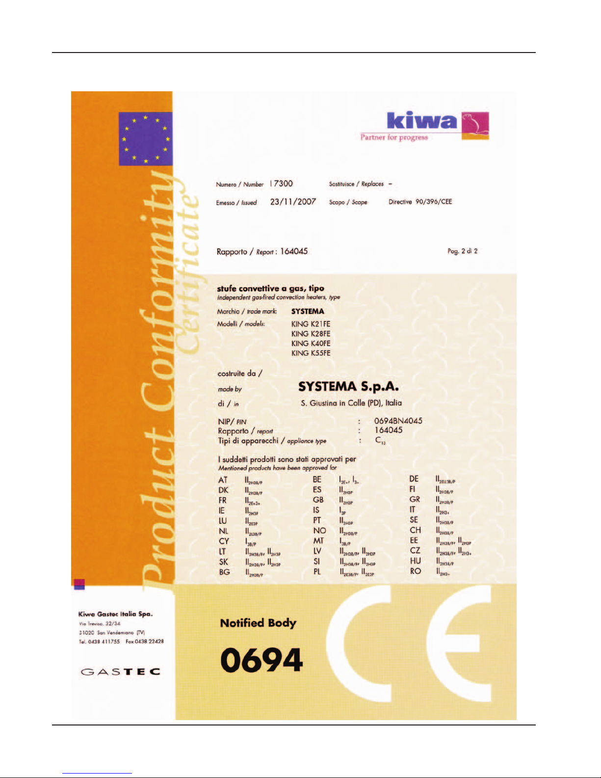
7 CE CERTIFICATE
Page 36

36
Rev. 12GB0712
SYSTEMA S.p.A.
AIRTIGHT GAS CONVECTORS
Page 37

37
Rev. 12GB0712
SYSTEMA S.p.A.
AIRTIGHT GAS CONVECTORS
Page 38
38
Rev. 12GB0712
SYSTEMA S.p.A.
AIRTIGHT GAS CONVECTORS
Page 39

39
Rev. 12GB0712
SYSTEMA S.p.A.
AIRTIGHT GAS CONVECTORS
Page 40

 Loading...