

Systema INFRA...ROSSO SCR 1 25M, INFRA...ROSSO SCR 1 45M, INFRA...ROSSO SCR 1 45A, INFRA...ROSSO SCR 1 25A Instruction Manual
Page 1
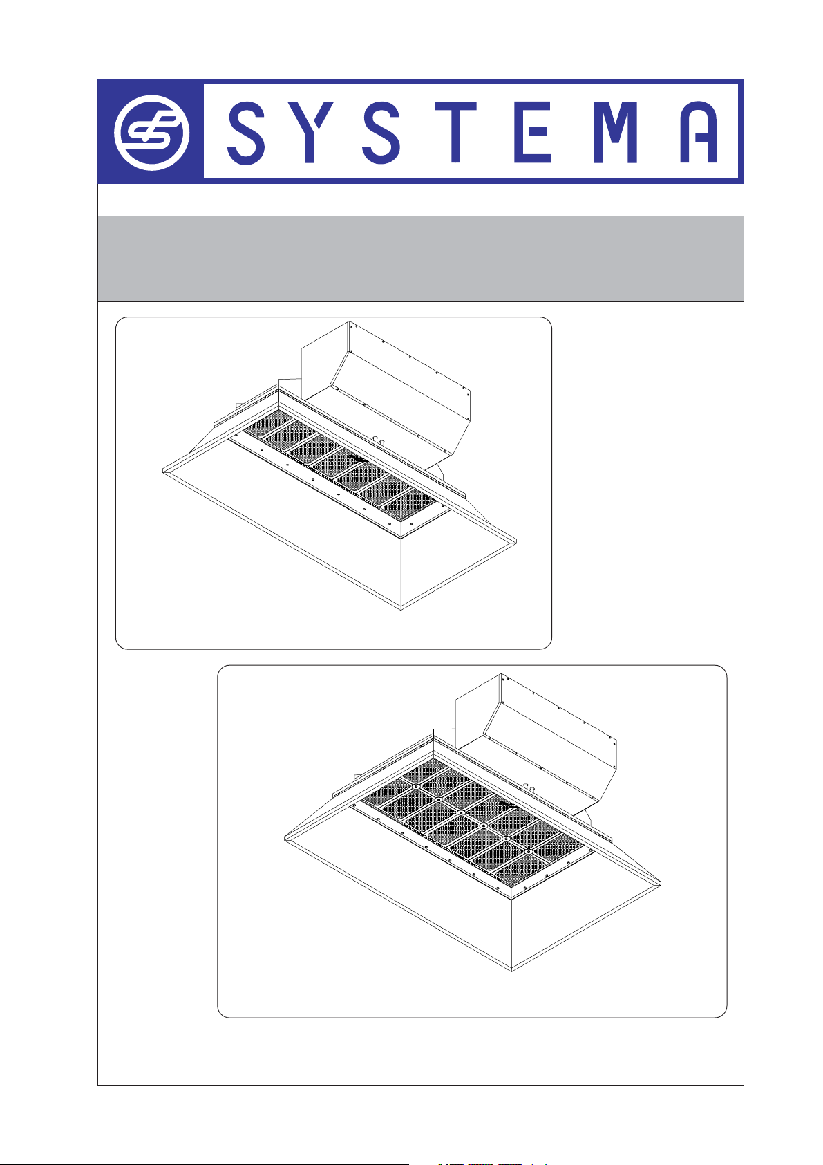
INFRA-RED VARIABLE POWER CERAMIC HEATERS
"INFRA…ROSSO SCR 1"
"INFRA…ROSSO SCR 1" 25m - 25a
REV. 03GB0602
"INFRA…ROSSO SCR 1" 45m - 45a
INSTRUCTIONS MANUAL
"INSTALLATION - USE - MAINTENANCE"
Page 2
SYSTEMA
!
IMPORTANT
Read carefully this manual before proceeding to the start up of the installation. In order to
improve the product, SYSTEMA reserves the right to modify the content without prior notice.
SYSTEMA S.p.A.
Via San Martino 17/23
S. GIUSTINA IN COLLE (PD)
loc. Fratte Fontane Bianche
PADOVA - ITALY
Tel. 0039 0499355663
Fax 0039 0499355699
E-mail: systema@systema.it
http://www.systema.it
Rev. 03GB0602
This product is manufactured and certified by
SYSTEMA S.p.A.
SYSTEMA POLSKA Sp. zo.o.
Ul. Szadkowska, 72
98-220 Zdunska Wola
Poland
Tel. +48 43 8247287
Fax +48 43 8233064
http://www.systemapolska.pl
E-mail: systema@systemapolska.pl
2
Page 3

SYSTEMA
Summary
1 GENERAL RULES ................................................................................................... 4
2 EQUIPMENTS DESCRIPTION .............................................................................. 5
2.1 General description ............................................................................................................. 5
2.2 Functionning description .....................................................................................................6
3 PACKING - TYPOLOGY AND DIMENSIONS .........................................................7
3.1 Ceramic heater packing ...................................................................................................... 7
3.2 External dimension of equipment packing ........................................................................ 7
3.3 Packing dimensions on pallet ............................................................................................. 7
4 TECHNICAL DATA ................................................................................................ 8
4.1 General technical data ........................................................................................................ 8
4.2 Thermal power table ........................................................................................................... 9
5 EQUIPMENT BASIC PARTS ............................................................................... 10
5.1 Fan characteristics ventilateur .......................................................................................... 10
5.2 Gas solenoid valve ............................................................................................................. 10
5.3 Flame control electronic device ....................................................................................... 10
5.4 Air - Gas mixer ................................................................................................................... 10
5.5 Ceramic plate .................................................................................................................................. 10
6 ELECTRICAL CONNECTIONS ............................................................................. 11
6.1 Wiring diagram SCR 25 m - SCR 45 m .............................................................................. 11
6.2 Fan digital PWM regulator ................................................................................................ 12
6.3 Wiring diagram of SCR 25 a - SCR 45 a ........................................................................... 13
6.4 Serial INFRANET network wiring diagram ....................................................................... 14
6.5 Master INET control board ................................................................................................. 14
7.1 EXPLODED DRAWING SCR 25m - SCR 45m equipments ................................................. 15
7.2 EXPLODED DRAWING SCR 25a - SCR 45a equipments .................................................. 15
7.3 Exploded Drawing SCR 25 m - SCR 25 a equipments ..................................................... 17
7.4 Exploded drawing SCR 45 m - SCR 45 a equipment ....................................................................... 18
8 "INFRA…ROSSO SCR" HEATERS INSTALLATION ......................................... 19
8.1 Security distance from inflammable materials ............................................................... 19
8.2 Ceiling installation ............................................................................................................. 20
8.3 Installation on a wall ......................................................................................................... 21
9 START UP AND OPERATING ............................................................................. 22
10 CHANGE OF FUEL SUPPLY .............................................................................. 23
10.1 Operating anomalies .........................................................................................................24
11 GUARANTY .......................................................................................................... 25
11.1 Object and validity of guaranty ......................................................................................... 25
11.2 Exclusions from guaranty .................................................................................................. 25
3
Rev. 03GB0602
Page 4

SYSTEMA
1 GENERAL RULES
This manual is an integral and essential part of this device and it must be carefully stored in its vicinity
for purposes of rapid consultation.
Read carefully the instructions and warnings provided herein because they provide important information
regarding safety, installation, use and maintenance.
In case of loss of the present manual, contact immediately the manufacturer.
ATTENTION!!
Being established that:
The "INFRA…ROSSO" ceramic heaters are heating according to the principle of visible radiation with
open air combustion.
The "INFRA…ROSSO" ceramic heaters have no chimney for the evacuation of exhausts outside, therefore
the combustion products remain in the premises mixed with the air. They will have to be ejected outside
by an adequate ventilation.
The ceramic plate of "INFRA…ROSSO" ceramic heater can reach temperatures of about 1.200 °C.
The "INFRA…ROSSO" ceramic heater need to be operated gas and electric energy.
The present manual does not indicate with absolute precision the type of places where these
equipments can be installed
For each installation, qualified personnel must evaluate the environment risk.
To make the installation easier , we strongly suggest to use the following basic suggestions:
The "INFRA…ROSSO" ceramic heater have to be installed in premises where there is absolutely no
risk of fire. The installation is forbidden in premises where gas or inflammable products are present or
where there is the risk that corrosive or inflammable gas could be generated.
The installation, control and maintenance of "INFRA…ROSSO" ceramic heaters have to be done in the
respect of laws, rules and good technique principles in force in the Country where the equipments are
installed.
The "INFRA…ROSSO" ceramic heaters have to be installed, verified and submitted to maintenance by
qualified personnel.
The "INFRA…ROSSO" ceramic heaters can be installed on a wall or on the ceiling, without any limit of
inclination, but with full respect of safety distances between the emitting source and the structure of the
building or the material present in the premises.
The premises where the "INFRA…ROSSO" ceramic heaters are installed will have to be
permanently ventilated in order to eject outside the combustion products. The minimum
ventilation admitted for the premises must respect the laws and the rules of the Country
where the installation is made.
The absence of ventilation in the premises is determining accumulation of CO2 and subsequently
carbon monoxide, which is a sign of bad functioning of "INFRA…ROSSO" ceramic heaters and
is very dangerous for the health of people and animals: in certain cases exhaust could be
cause of death for people and animals.
ATTENTION!
In the case the ceramic heaters are not compatible with the use, by the safety standpoint, we
invite you to consider our products INFRA B (airtight gas radiant tubes) and OHA (airtight gas
radiant strips).
Rev. 03GB0602
4
Page 5
SYSTEMA
2 EQUIPMENTS DESCRIPTION
2.1 General description
The "INFRA…ROSSO" ceramic heaters have to be considered as new generation products because
they are based on new innovating concepts : a pre-mix burner, the very high thermal performance, the
modularity of thermal power, the radiating performance, the highest flexibility of installation and use.
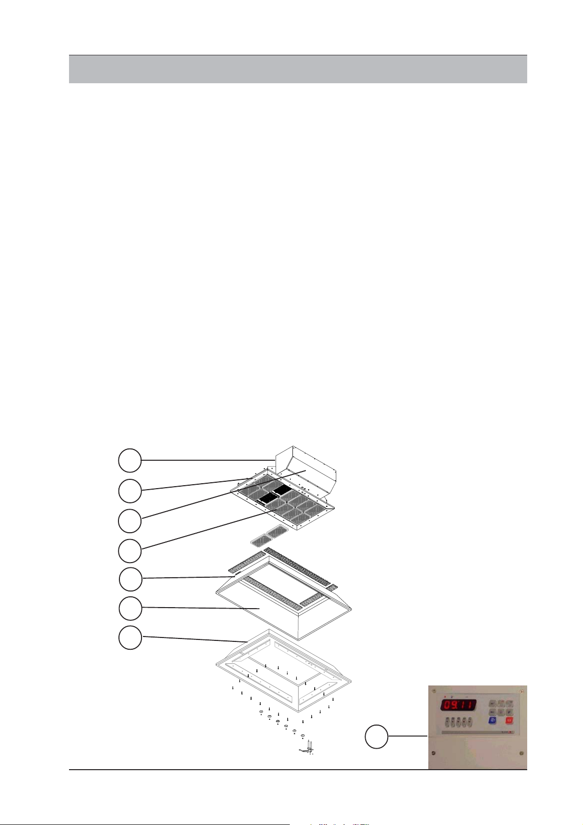
The "INFRA…ROSSO" ceramic heaters consist in
a) A steel chamber where takes place the mixing of air and gas.
b) A waterproof box containing the equipment, with the possibility of installation of air filters or
connection with a duct taking the air form outside. NEW !
c) Pre-mixed system of combustion, with a variable speed fan and modulating gas valve, working in
depression conditions. NEW !
d) Emitting source (burner) : a ceramic plate.
e) A standard stainless steel parabola reflector or (in option) a sandwich consisting inside in a
parabola reflector in aluminized and calorized steel with quartz finishing (e1) with high reflection and
infrared emission characteristics NEW !, a thermal isolating sheet (e2) NEW ! and an external parabola
in galvanized steel, for protection and isolation (e).
f) In the models …m (manual) the thermal power can be regulated manually with digital variation of
power within the modulation range of the model.
The thermal power modification can be by cable remote control, manual on the electric board or by
infrared remote control. NEW !
g) The centralized control of the heaters for the models …a (automatic) consist in the INET serial
network, with a regulation which is independent by the thermal power of each thermal zone, with the
integral proportional method (thermal power variation based on the established comfort temperature and
on the detected ambient temperature). NEW !
b
a
c
d
e
e2
e1
g
5
Rev. 03GB0602
Page 6

SYSTEMA
2.2 Functionning description
The "INFRA…ROSSO" ceramic heaters models are the following:
a) Mod. SCR 25 m with pre-mix combustion and manual variation of thermal power.
b) Mod. SCR 45 m with pre-mix combustion and manual variation of thermal power.
c) Mod. SCR 25 a with pre-mix combustion and automatic variation of thermal power by a InfraNet
control network and a Inet electric board (see specifications in the following paragraphs).
d) Mod. SCR 45 a with pre-mix combustion and automatic variation of thermal power by a InfraNet
control network and a Inet electric board (see specifications in the following paragraphs).
The functioning procedure of the over described models can be resumed in the following points :
A) The models …m (manual), with the digital PWM variator situated inside the equipment are regulated
at the factory during the final control before delivery to the thermal power requested (see table at
paragraph 2.3).
The demanded power will remain fix. If necessary it will be possible to modify the power according the
climate conditions of the moment, by the ground control board, using a linear potentiometer or by a
remote infrared control (optional).
The models …m (manual) with the remote control, will be programmed with the power requested by the
final user (see table at paragraph 2.3) and they will be controlled by a ON/OFF ambient thermostat.
Sequence of functioning of models …m (manual):
After the reception of the electric input, the lighting and start up procedure begins, with the following
steps :
1) The 577 DBC device starts the fan for the mixing chamber washing, for a minimum of 10 seconds.
The fan will start at the maximum speed, for a determined time, then it twill go down to the
programmed speed with the digital PWM variator.
2) When the washing stage is completed, the lighting discharge takes place for a minimum of ten
seconds (Ts 10) ; in the same time the gas valve 848 Sigma will be put in the open position by
electronic card.
3) The 848 Sigma gas valve will supply the gas at a pressure equal to the depression generated by
the fan (for instance fan depression 5 mbar > pressure delivered by the valve 5 mbar > pressure
read downstream the valve = 0).
4) The mixture generated inside the mixing chamber will be lighted on the ceramic plate. After a time
interval Ts the ignition discharge will stop and the electrode will switch automatically to the function
of flame detection.
If lighting will not take place or the flame will not be detected, the 577 DBC device, after a time interval
of 20 seconds, will make a second lighting attempt.
The equipment reset is of electric type with extinction and new lighting of electric supply.
5) The power at start up will be equal to the maximum power of the heater for the time interval
programmed in the PWM variator. After this lighting step, the thermal power of the heater will be
the one which will have been established (for instance : for SCR 25 m - programmed power PWM
20% - Start at 70% of PWM corresponding to 24 kW/h - After the start up time, the thermal flow
of the heater will be the one which will have been fixed PWM 20% = 12 kW/h).
B) The models…a (automatic) will be different from the manual models only by the standpoint of
control of the emitted power which in the manual models can be selected manually while in the
automatic models the thermal power is modulated by the master INET electric board (which is
outside the heater) as a function of the temperature detected in the ambient air, compared with
the established temperatures of manual models (SET POINT).
The master INET electric board, will change with the proportional integrated the fan speed and, as a
consequence, the gas flow and the emitted power.
The lighting sequence for the automatic models will be the one shown at the previous points 1-2-3-4.
Rev. 03GB0602
6
Page 7
SYSTEMA
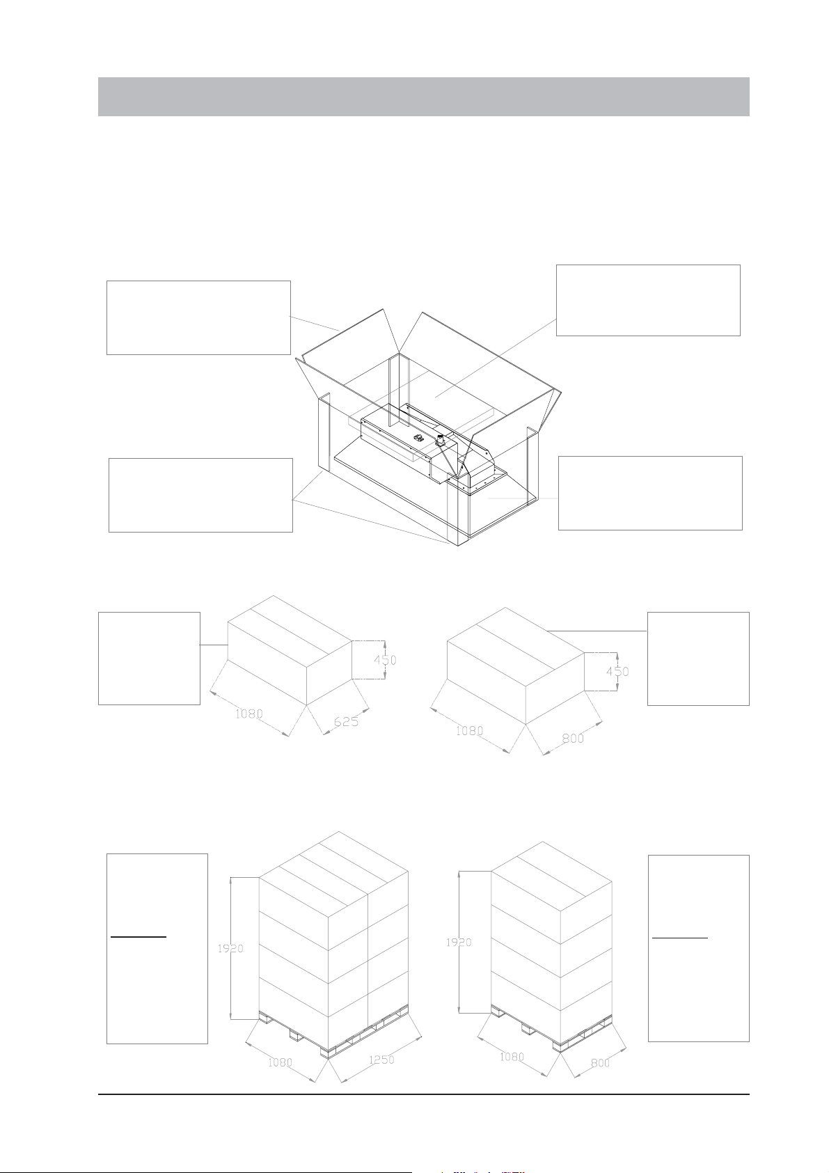
3 PACKING - TYPOLOGY AND DIMENSIONS
The "INFRA…ROSSO SRC1" ceramic heaters are delivered completely assembled, ready to be installed in
their definitive position. They are packed for transportation inside reinforced cardboard boxes.
This cardboard box contains the ceramic heater and this manual.
The supports (if requested), the electric control board or thermostat and accessories, are delivered in separate
packages
3.1 Ceramic heater packing
Upper protection
Equipment packing
cardboard box
polystyrene
Rainforce corner
cardboard
3.2 External dimension of equipment packing
Equipment
packing for
SCR 25 a/m
23 Kg
3.3 Packing dimensions on pallet
Packing on
pallet 8 units
SCR 25
184 Kg
Ceramic heater
"INFRA…ROSSO SCR1"
Equipment
packing for
SCR 45 a/m
32 Kg
Packing on
pallet 4 units
SCR 45
128 Kg
7
Rev. 03GB0602
Page 8
SYSTEMA
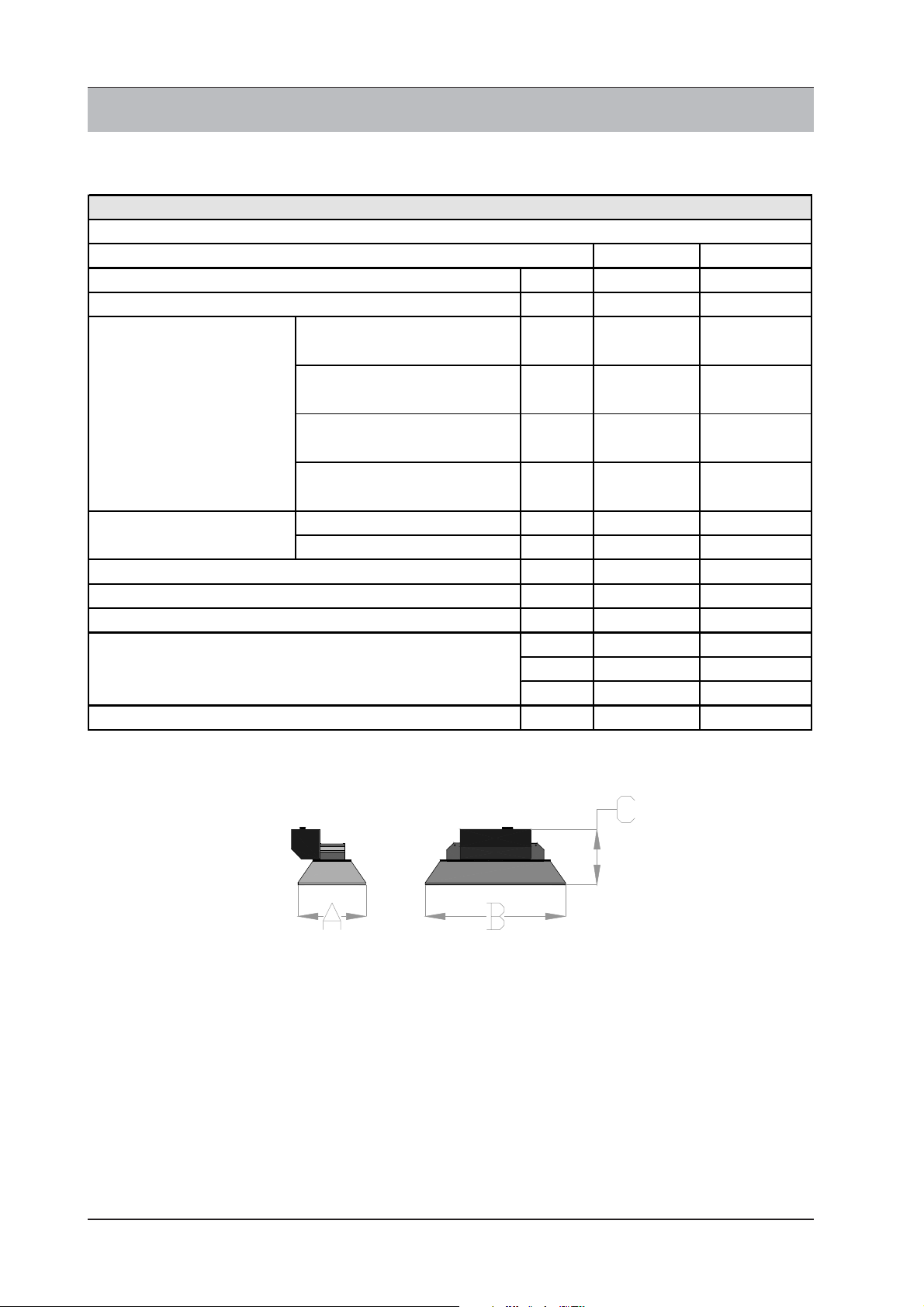
4 TECHNICAL DATA
4.1 General technical data
"INFRA…ROSSO” SRC CERAMIC HEATER
TECHNICAL CHARACTERISTICS
MODELES
THERMAL FLOW (maximum nominal)
THERMAL FLOW (minimum nominal)
Maximum
Natural gas G2O
CONSUMPTION
Nominal at 15°C and
1013,25 mbar
NOZZLE DIAMETER
ELECTRICAL SUPPLY
MAX ELECTRICAL POWER absorbed
GAS CONNEXION (M)
DIME NSIONS
WEIGHT (standard version)
Minimum
Natural gas G2O
Maximum
L.P.G. Propane G31
Minimum
L.P.G. Propane G31
Natural gas G20 mm 3,7 5,5
L.P.G. Propane G31 mm 3 4,1
SCR 25a/m SCR 45 a/m
kW (HI) 24 48
kW (HI) 12 24
3
Nm
/h
3
Nm
/h
kg/h 1,86 3,72
kg/h 0,93 1,86
V/Hz 230/50 230/50
W60 60
" 3/4" 3/4"
mm A) 514 A) 514
mm B) 1055 B) 1055
mm C) 418 C) 418
kg 27 36
2,54 5.08
1,27 2.54
Rev. 03GB0602
8
Page 9
SYSTEMA
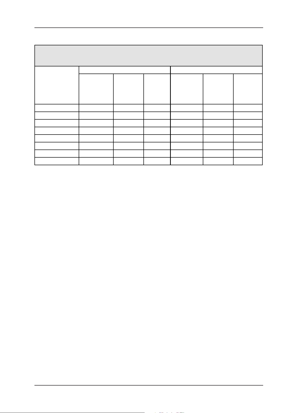
4.2 Thermal power table
CERAMIC HEATER “INFRA…ROSSO” SCR 25 a/m - SCR 45 a /m
NOMINAL THERMAL FLOW AND GAS CONSUMPTION AT REGULATION LEVEL
SRC 25a/m SRC 45a /m
REGULATION
LEVEL PWM
THERMAL
FLOW
kW
NAT.GAS
G20
3
Nm
/h
L.P.G.
G31
kg/h
THERMAL
FLOW
kW
NAT.GAS
G20
3
Nm
/h
0,25 12 1,27 0,93 24 2,54 1,86
0,3 15 1,58 1,16 32 3,38 2,48
0,35 18 1,9 1,39 36 3,81 2,79
0,4 20 2,11 1,54 40 4,23 3,1
0,45 22 2,32 1,69 42 4,44 3,25
0,5 24 2,54 1,86 44 4,66 3,41
0,55 ----------- ----------- ----------- 46 4,87 3,56
0,6 ----------- ----------- ----------- 48 5,08 3,72
L.P.G.
G31
kg/h
9
Rev. 03GB0602
Page 10

SYSTEMA
5 EQUIPMENT BASIC PARTS
5.1 Fan characteristics ventilateur
Manufacturer .................................................................................................... L.N.
type ................................................................................................................. EVB 30-230
electrical supply ............................................................................................... 230 V ~ 50 Hz
electrical power ................................................................................................ 50 W
protection degree ............................................................................................. IP 40
maximum rotation speed (r.p.m.) ...................................................................... 4200
5.2 Gas solenoid valve
Manufacturer .................................................................................................... SIT CONTROLS
type ................................................................................................................. 848 SIGMA
functioning........................................................................................................ pneumatic modulating
electrical supply ............................................................................................... 230 V ~ 50 Hz
electrical power ................................................................................................ 6 W
protection degree ............................................................................................. IP 40
stopping delay .................................................................................................. <1 sec.
temperature of use ........................................................................................... 0 ÷ 60 °C
inlet maximum pressure ................................................................................... 60 mbar
outlet pressure ................................................................................................. variable
5.3 Flame control electronic device
Manufacturer .................................................................................................... SIT CONTROLS
type ................................................................................................................. 577 DBC
electric supply .................................................................................................. 230 V ~ 50/60 Hz
protection degree ............................................................................................. IP 40
pre-washing time (TW) ..................................................................................... 10 sec.
security time (TS)............................................................................................. max. 10 sec.
security time at extinction ................................................................................ <1 sec.
ignition attempts .............................................................................................. 2
time interval between ignition attempts ............................................................. 10 sec.
resetting type ................................................................................................... electrical
electrodes ........................................................................................................ 1
5.4 Air - Gas mixer
Manufacturer .................................................................................................... SIT CONTROLS
type ................................................................................................................. 391 AGM
5.5 Ceramic plate
Manufacturer .................................................................................................... BRAY
type ................................................................................................................. Ceramic plaque
dimensions ...................................................................................................... 179x104x13 mm
Maximum operating temperature ...................................................................... 1200 °C
Rev. 03GB0602
10
Page 11

SYSTEMA
6 ELECTRICAL CONNECTIONS
6.1 Wiring diagram SCR 25 m - SCR 45 m
The following wiring diagram for "INFRA…ROSSO" SCR 25 m and 45 m ceramic heater concern only the
internal connections of the equipment.
The external connections of the equipment are under the responsibility of the installation technicians and they
must respect the laws and the rules of the Country where the installation has been made.
SPARK
1 Fan E VB 30 230-S 29 3 poles plu g for fan connection
11 Plug elec tri c s uppl y 230 V. 3 Burner
12 Male fastom for ground connection 31 Ignition and flam e dete ct ion el ec trode
13 PV N conn ect ion 32 Ground ele ct rode
2 Flame co ntrol device 577 DBC 33 Silicon. cable for equipmen t c onnec ti on
21 MOLEX 12 poles connector 34 ground connect ion wire
22 Male fastom 3*0,7 ignit ion c able 4 PW M fan digital reg ulat or
23 Male fastom groun d connect ion valve body 41 Remote potent iom ete r 10 K (optional)
24 Cable 3*0,5 m m² main electric al s upply 42 3 poles plugs potentiometer connec tion
25 Cable 3*0,5 m m² fan electric al s uppl y 5 Control board (optional)
26 Cable 2*0,5 mm² remote stop warning 51 Electri cal supply 230 V. 50 Hz phase/ground/neutral
27 5 poles plug for elec tri cal connect ion 52 Prot ectio n fuse Max 3 A
F1 Fuse 3,15 A. 53 Infrared sens itive ambient thermos t at
Free 5 poles plug for elect ric al c onnect ion 54 Green warning light burner O N - Connection L2
Connec tions : 55 Red warning light burner STOP - Connex ion L 1
L1 - phas e cha rge 230 V . s top warning 7 Ground equipo tent ial poi nt
28
L2 - phas e cha rge 230 V . opera ting warning
PE - ground c onnecti on
N - neutral line 230 V. 50 Hz
L3 - phas e line 230 V. 50 Hz
11
Rev. 03GB0602
Page 12

SYSTEMA
6.2 Fan digital PWM regulator
The fan speed is fixed by the digital regulator situated inside the equipment box.
For each model the manufacturer is programming the minimum and maximum value of PWM which will determine
the minimum and maximum thermal power of the ceramic heater (for instance : PWM minimum 25% = 12 kW
- PWM maximum 60% = 24 kW) with no possibility of modification by the final user. In this interval, it's possible
to choose the requested thermal power, fixing a value, acting on the digital regulator situated inside the equipment
box.
For operational needs, it's possible to modify the thermal power from a place accessible by the operator by a
10 K potentiometer (optional) connected to the contact 1 and 2 of digital regulator, at a maximum distance of
15 m.
To fix the thermal power, the digital PWM regulator must be used. In order to modify the thermal power press
SET, find the percent desired value using the arrows up and down and confirm pressing SET.
Attention!
The percent maximum value which is fixed corresponds to the maximum thermal power of the heater and the
percent minimum value of PWM corresponds to the minimum thermal power of the heater.
THE FIXED PWM VALUES ARE UNCHANGEABLE AND THEY CAN BE MODIFIED ONLY AND EXCLUSIVELY
BY THE MANUFACTURER
DIGITAL PWM PROGRAMMING
1) Press at the same time the switch UP and DOWN (switches avec the arrows) for a few seconds.
2) Select with the switches the parameters to be modified
3) Press SET, modify the parameters, press SET to go out
4) When programming is finished, wait 30 seconds to memorize the new program
Operation paramete rs of digital control PWM SCP 960/A
cod. parameter interv al unit def
Ope ration parameters
Presence potentiometer 10 k for remote variation PWM 0…1 –
Р
Regulation parameters
Minimum level PWM 0… rH %
rL
Maximum level PWM 0…99 %
rH
Output parameters
Boos t period (starting time at maximum PW M)
Lb
Othe r parameters
Keyboard Block 0=NO, 1=YES 0…1
HL
Pass word activation 0=NO, 1=YES 0…1
HP
Thermal power change example:
1) Take out the cover of the equipment box
2) Act on the digital PWM control like indicated in the example
0…99 с
65/45
0
25
60
0
0
VALUE ACTUALLY
SET UP
NEW VALUE SET UP SEE
TABLE AT PAGE 9 FOR THE
CORRESPONDENCE OF
THERMAL POWERS
Rev. 03GB0602
3) PRESS THE SWITCH SET
4) PRESS THE ARROWS TO SELECT
THE NEW VALUE
5) PRESS THE SWITCH SET TO
MEMORIZE THE NEW VALUE
12
Page 13

SYSTEMA
6.3 Wiring diagram of SCR 25 a - SCR 45 a
The following wiring diagram for the "INFRA…ROSSO" ceramic heaters SCR 25a and 45 a concerns exclusively
the internal connections of the equipment.
The external connections of the equipment up to the Master INFRANET board will be illustrated in the following
paragraphs.
The power supply connections will be at the charge of the technicians charged of installation and they must
respect the laws and rules in force in the Country were the installation is made.
SPARK
1 Fan EVB 30 230-S 6 INFRANET network module interface
11 Plug electrical supply 230 V.
12 Male fastom for ground connection 1- Connection stop warning light
13 PV N connection 2- Connection operating warning light
2 Flame c ontrol device 577 DBC 3-Neutral 230 V. 50 Hz power supply
21 MOLEX 12 poles c onnector 4 -Phase 230 V. 50 Hz power supply
22 Male fastom 3*0,7 ignition cable Serial INET network connection terminals
23 Male fastom ground connection valve body 13-Connection +A
24 Cable 3*0,5 mm² main electrical supply 14-Connection -B
25 Cable 3*0,5 mm² fan electrical supply 15-Connection of protection to ground
26 Cable 2*0,5 mm² rem ote stop warning 63 11 - 12 Thermos tat connection
27 3 poles plug for electrical supply 64 Code Switch devic e
28 Free 3 poles electrical supply PW M fan connection terminals
29 3 poles fan connection 21-PW M signal
3 Burner 22-Ps + s upply
31 Ignition and flame detector electrode 23-Ps - supply
32 Ground electrode 66 S erial INET line sect. 2x 0,5 mm ² and screen ground
33 Silicon cable for equipm ent connection 67 3 poles INET plugs > L1=+A N=-B PE=S
34 Ground connection cable 7 Ground equipotential point
5 Electrical supply 230 V . 50 Hz phas e/ground/neutral
Electrical supply 230 V. 50 Hz and warning lights
terminals and warning
61
62
65
13
Rev. 03GB0602
Page 14

SYSTEMA
6.4 Serial INFRANET network wiring diagram
The INFRANET network allows to control from just one Master INET control board from a minimum of one SCR
25a/45a ceramic heater to a maximum of 16 SCR 25a/45a ceramic heaters divided in 4 independent zones.
The following wiring diagram for "INFRA…ROSSO SCR 25a et 45a ceramic heaters shows the connections to
the INFRANET network.
The detailed instructions for the connections are available in the Master INET instruction manual.
General switch
1
Master INET c ontrol board
2
Hemispherical infrared sensitive probe
3
Thermal zone (4 for 4 ceramic heaters)
4
Ceramic heaters
5
General electrical s upply 230 V.
6
phase/ground/neutral
Serial INFRANET cable (2 poles cable
7
with protection connected to ground)
Hemispherical probes cables
8
6.5 Master INET control board
The INET control board can control at maximum 16 ceramic heaters "SCR…a".
The main characteristics are :
- PVC box
- Not authorized tampering with access to password for programming
- Membrane keyboard for all programming
- Sequential display of all detected temperatures
- 4 independent working zones in standard operating conditions at comfort temperature and antifreeze program
- Possibility to install 4 heaters for each zone
- Independent operation for each zone and each heater (on/off)
- Daily or weekly temperature programmer for each zone
- External probe (optional) for functioning with optimization (pre-lighting of heaters as a function of
the external temperature)
- Connection and control by PC (optional)
For further information on operating conditions of Master INET control board, consult the technical
manual for INET control board installation.
Rev. 03GB0602
14
Page 15

SYSTEMA
7.1 EXPLODED DRAWING SCR 25m - SCR 45m equipments
1
2
3
22
16
10
4
5
7
6
9
11
8
12
13
14
15
29
25
26
27
28
30
32
33
17
18
23
21
19
20
24
7.2 EXPLODED DRAWING SCR 25a - SCR 45a equipments
41
36
27
37
42
43
28
33
30
32
24
35
3829 30
4031
39
15
34
Rev. 03GB0602
Page 16

SYSTEMA
a
Pos. Code # Description 1 Gas solenoid valve fastening bracket
1 1 Main equipment body 2 M 5X35 mm. zinc plated sc rew
2 2 M 5x15 mm. bolt 14 5x10 mm zinc plated washer.
3 1 Thermal isolation of equipment box 24 1 SIT 577DBC flame control device
4 1 Equipment box 25 1 M4 x 40 mm. fas t ening s c rew
5 1 Electrical equipment bracket 26 1
7 4 Thermal isolation of fan 27 1 Fan connect ion electric plug
8 1 Evb 30 centrifuge fan 28 1
9 1 Digital variator PWM 29 1
11
12 1 Air/gas mixer 32
13
14
15 1 Injector nozzle bracket 35 1
16
17 1 Aluminium gasket 40 1 4 x 8 mm. self tapping screw
18 2 Female ¾ collar 41 1 Equipment box
19 1 Sit 848 Sigma solenoid valve 42 1 Equipment box cover
20 1 ¾ female/female connector 43 14 4,2 x 8 mm. self tapping
21 1 Male ¾ threaded connector
22
4M 5 nut 30 1
4 5x14 mm. zinc plated washer 31 1 Electrodes fastening
1 Air flow regulator for SCR 25 m/a 1
1 Air flow regulator for SCR 45 m/a 2 5 x 10 mm. zinc plated washer
3 M 4 x 10 mm. zinc plated screw 1 5 mm. zinc plated washer
3 4 x 8 z inc plated washer 2 M 5 nut
3 mm² LPG nozz le for SCR 25 m/a
1
3,7 mm² natural gas
1 G20 nozzle for SCR 25 m/a 37 1
1 4,1 mm² LPG nozzle for SCR 45 m/
5,5 mm² natural gas G20 nozz le for
1
SCR 45 m /a
Sit 848 Sigma solenoid valve
1
bracket
1 M5 pressure nut
23
5x10 mm. s elf tapping screw to fix
the box cover
Plug for electrical connection to
external supply line
Lighting and flame detection
connection cable
Ignition and flame detection
electrode ground c onnection cable
Green/yellow cable for solenoid
valve ground connection
M 5x35 mm. zinc plated screw for
equipotential ground connection
33
5 poles connection cable of external
card to the equipment
36 1 3 poles cable for fan connection
Box of electronic device for
automatic SCR models
38 1 Ignition/flame control electrode
39 1 Ground electrode
Rev. 03GB0602
16
Page 17

7.3 Exploded Drawing SCR 25 m - SCR 25 a equipments
1
2
3
4
5
SYSTEMA
10
6
7
8
9
Position Code Qty Description
1 18 M 5 s tainless steel nut
2 1 Equipment body
3 1 Thermal isolation
4 7 Ceramic plate
5 4 Ceramic fiber thermal isolation
61
7 4 Fas tening bars
818
9 2 Electrodes
Stainless steel parabola
reflector
M 5 x 25 mm. stainless steel
bolts
10 4 3,5 x 5 mm. self tapping screw
17
Rev. 03GB0602
Page 18

SYSTEMA
7.4 Exploded drawing SCR 45 m - SCR 45 a equipment
1
2
3
4
5
6
7
8
9
10
11
12
13
Position Code Qty Description
122
21
34
414
56
66
74
8
91
10 4
11 22
12 1
13 4
M 5 stainless steel nut
Equipment body
Thermal isolation
Ceramic pl ate
5 x16 stainless st eel washer
M 5 stainless steel nuts
Ceramic fiber thermal isolation
Stainless steel parabola reflector (standard)
1
Calorized steel parabola reflector (optional)
1
Galvanized steel parabola reflector (optional)
Fastening bars
M 5 x 25 mm. stainless steel bolts
Electrodes set - 2 pieces
3,5 x 5 mm. self tapping screw
Rev. 03GB0602
18
Page 19

SYSTEMA
8 "INFRA…ROSSO SCR" HEATERS INSTALLATION
The "INFRA…ROSSO SCR" ceramic heaters can be installed only in premises which are compatible with this
type of equipment. Before deciding the installation a project has to be done by a qualified technician, who has
to evaluate the environmental risk.
THE INSTALLATION OF "INFRA…ROSSO SCR" CERAMIC HEATERS MUST RESPECT THE LAWS AND
THE RULES IN FORCE IN THE COUNTRY WHERE THE INSTALLATION IS MADE.
THE PRODUCT IN OBJET HAVE BEEN CERTIFIED BY THE FONCTIONNING SAFETY STANDPOINT.
THE MANUFACTURER WILL HAVE NO RESPONSIBILITY FOR INADEQUATE OR RISKY INSTALLATIONS
The electrical connections and the gas connections have to be realized by qualified technicians, in
the full respect of lows and rules in force in the Country were the installation is made.
8.1 Security distance from inflammable materials
MINIMUM DISTANCES BETWEEN THE HEATER AND THE INFLAMMABLE MATERIALS
(wood, cardboard, plastic products, pallets etc.)
ACCORDING TO :
- DIN 3372 Section 6 paragraph 3.12
- DVGW, G63/11, section 12/3.1.2
- Minimum distance suggested "A" > 4 m.
- Minimum distance suggested "B" > 0,5 m.
- Minimum distance suggested "C" > 1,5 m.
In any case, the distance must be such that the maximum surface temperature of any material is below 85°C
Supporting and fastening devices must reach temperatures below 50°C.
19
Rev. 03GB0602
Page 20

SYSTEMA
8.2 Ceiling installation
THE "INFRA…ROSSO SCR1" CERAMIC HEATERS ARE PERFECTLY FONCTIONNING IN ANY POSITION
AND WITH ANY INCLINATION.
The "INFRA…ROSSO SCR1" ceramic heaters, installed at the ceiling have to be fixed in an adequate manner,
in order to avoid hunting or risk of crash.
The distance from the ceiling or from the supporting structure will have to be in conformity with the indications
of paragraph 8.1.
The installation of the ceramic heaters must be perfectly horizontal, unless there are practical reasons to take
into account.
The minimum installation height suggested is 4 m. from floor.
The maximum installation height suggested is 15÷18 m. for models SCR 25 m/a and 20÷25 m. for models SCR
45 m/a
Pos. Description Indicati ons for install ation
“INFRA…ROSSO” ceramic
1
heaterSCR 25/45 m/a
“INFRA…ROSSO” ceramic heater
2
SCR 25/ 45 m/ a
Supporting s t ructure
3
Elec t rical connect ions
4
Gas connection
5
Flexibl e connection
6
Inclinati on angl e The minimum incli nat ion angle i s 0° both sides.
7
Convecti ve flow of exhaust
8
Lateral vi ew of inst allat ion
Front vi ew of install at ion
Use rigid material t o avoid oscil lati on movement s (for
instance Ø 8 mm. steel bars)
The elect ri cal connection has to be done in conformit y
with laws an rul es of t he Country were the inst al lation is
made.
The cables have to be install ed far from the flow of
combust i on product s , if possi ble inside t he equipment.
For the manual models :
Power supply line c oming from INET cont rol board 230 V
(alternate c urrent ) 50 Hz wit h ground connection cable.
Eventual 2 poles cable for remote st op warning l ight.
For the automatic models :
Power supply line c oming from INET cont rol board 230 V
(alternate c urrent ) 50 Hz wit h ground connection cable.
Serial cable 2 poles with mini mum sec tion 0, 5 sq. mm,
with protec t ion connect ed to ground.
The gas connec t ion has to be done in conformity wit h
laws and rules of the Country were the inst all at ion is
made.
The pipes have to be inst alled far from the flow of
combust i on product s , if possi ble inside t he equipment.
In order t o allow a good functioni ng of t he SIGMA
solenoid val ve and for t he general s afet y of ins t allat ion,
the gas supply pres sure has to be lower than :
50 mbar for LPG, propane and butane
20 mbar for natural gas
The final connection t o t he gas suppl y line has t o be
done with a metall ic flex ible pi pe.
Verify that t he fl ow does not meet s upporting structures,
electrical l ines , gas pipes.
Rev. 03GB0602
20
Page 21

8.3 Installation on a wall
12
SYSTEMA
10
9
5
13
11
Pos. Description Indications for installation
14
“INFRA… ROS SO” ceramic heater
1
SCR 25/45 m/a
“INFRA… ROS SO” ceramic heater
2
SCR 25/45 m/a
Supporting struc ture
3
Allaciamento elettrico
4
Gas connec tion
5
Flexible connection
6
Inclination angle The minimum inclination angle is 0° both sides.
7
Convective flow of exhaust
8
Lateral view of installation
Front view of installation
Use rigid material to avoid osc illation movem ent s
(for instance Ø 8 mm. steel bars)
The electric al c onnection has t o be done in conformity
with laws an rules of the Country were the installation is
made.
The cables have to be installed far from the flow of
combustion products, if pos sible inside the equipment.
For the manual models :
Power supply line coming from INET cont rol board 230 V
(alternate c urrent ) 50 Hz with ground c onnect ion c able.
Eventual 2 poles cable for remote s top warning light .
For the automatic models :
Power supply line coming from INET cont rol board 230 V
(alternate c urrent ) 50 Hz with ground c onnect ion c able.
Serial cable 2 poles with minimum section 0,5 sq.mm,
with protection connected to ground.
The gas connec tion has t o be done in conformit y with
laws and rules of the Country were the installation is
made.
The pipes have to be installed far from the flow of
combustion products, if pos sible inside the equipment.
In order to allow a good func tioning of the SIGMA
solenoid valve and for the general safety of ins tallat ion,
the gas supply pres sure has to be lower than :
50 mbar for LPG, propane and butane
20 mbar for nat ural gas
The final connection to the gas supply line has to be
done with a metallic flexible pipe.
Verify that the flow does not meet supporting s tructures,
electric al lines , gas pipes.
21
Rev. 03GB0602
Page 22

SYSTEMA
9 START UP AND OPERATING
Before starting up the equipment, verify
1) The correct installation of the equipment :
2) The respect of safety conditions.
3) Verify the gas pipeline and if necessary purge the gas pipes.
4) VERIFY THE PRESSURE AND THE TYPE OF GAS SUPPLY.
5) Verify the electrical installation and THE RESPECT OF POLARITIES PHASE/NEUTRAL/GROUND
After these controls it will be possible to start the ignition procedure using the control boards of the equipment.
THE CERAMIC HEATER "INFRA…ROSSO SCR" IS TOTALLY REGULATED BY THE MANUFACTURER
DURING THE FINAL CONTROL AT THE FACTORY AND READY FOR USE.
DO NOT MODIFY AIR ANG GAS REGULATIONS INSIDE THE EQUIPMENT
Electrical
Signal
1
8
4
10
Ignition
effected
Burner
in
FUNCTION
IGNITION
PREWASHING
Tw 10 sec.
Ts 10 sec.
Ignition
failure
PREWASHING
Tw 10 sec.
IGNITION
Ts 10 sec.
Waiting time
10 sec.
First ignition cycle Second ignition cycle
Pos. Description Indications for start up a nd operating control
1 848 Sigma solenoid valve
2 E lec tri cal c onnec tor Direct c onnec ti on 577 DBC device
3Gas inlet
4 Gas ou tlet
56Gas INLET pres sure co ntrol point
2
3
9
7
56
Gas OUTLET pressure control
point
7 Con nection of depres si on s ignal Not in us e :
Regula tion of the max imum gas
8
flow
10 Connec ti on of pres s ure signal Not in use :
Ac cess to meas ure t he gas su pply pres sur e
The gas suppl y p ressure
- 50 mb ar for L. P. G., propa ne and bu tane
- 20 mb ar for nat ural gas
The gas suppl y p ressure
- 15 mb ar for L. P. G., propa ne and bu tane
- 15 mb ar for nat ural gas
Ac cess to meas ure t he gas pres sure at the bu rner.
During the pre washing pro ced ure the meas ure gi ve a
depres sion whi ch i s proport ional to t he fan s peed (for
ins t. : m ax imu m power heater - 12 m bar)
During funct ioni ng the mea sure gives the gas pres sur e
outlet.
THE MEASURED VALUE MUST BE ZERO. (The Sigma
sol enoi d valve com pens ate the meas ured depress ion
with the same gas pressure)
Sc rew for regu lation of m aximum gas flow.
THE RE GU LA TOR IS EXCLUDE D, THE SCRE W IS
COM PL ETE LY OPEN : DO NOT MODIFY
The sc rew c los ing i s determ ini ng a redu ct ion o f gas fl ow
and a c ons equent dec rease of burne r thermal p ower.
Use only on manufacturer request
it must be completely open
it must be completely open
Ignition
effected
Ignition
failure
has to be l ower than :
has to be h igher than :
Burner
in
FUNCTION
Equipment
on
STOP
2
7
Rev. 03GB0602
Pos. Description I ndicati ons for start up and ope rating control
1 EVB 30 Fan
2 Ai r/g as M ixer 391 A GM
Air flow regulator3
4 Gas inlet co nnec ti on
5 Primary air inlet Proportional to fan speed
6 Secondary air inlet
4 5
3
6
1
7 M ixer tightening s crew THIS SCREW MUST BE COMPLETELY TIGHTEN
- In SCR 25 models the secondary air is not regulated
(regulator closed)
- In SCR 45 a/ m mo dels the s ec ondary air i s regu lat ed :
the regu lat or has som e openi ngs .
DO NOT MODIFY THE POSITION.
the m anufacturer during th e final cont rol.
It will be possible to regulate the air flow by turning
clockwise the regulator, or vice vers a, only on demand of
the m anufac tur er and in ex cepti onal c ase s (re duct ion of
thermal flow in case of change of gas type - decrease of
temperature of ceramic plates)
Series of holes for secondary air only on regulator for
SCR 45 m
T he r egulat ion is ma de by
22
Page 23

SYSTEMA
10 CHANGE OF FUEL SUPPLY
The change of fuel type must be done by qualified personnel in the respect of security rules in force.
The manufacturer refuse any responsibility in case of damages due to a wrong transformation or an
inadequate and/or incorrect use of the equipment.
Gas type change
1) Close gas supply and cut off electrical supply
2) Disconnect the electronic device (1)
3) Disconnect the flexible gas connection
4) Disconnect the part (3) from its support (2)
5) Separate the part (3) from the solenoid valve (4)
6) Take out the Sigma solenoid valve and the nozzle (6) of air/gas mixer
7) Unscrew the injector (6) from the collar (8) and keep the aluminium gasket
8) Replace the nozzle (7) situated inside the injector (6)
9) Reassemble the equipment in the contrary order of disassembling
ATTENTION !! NO REGULATION HAS TO BE DONE AFTER THE MODIFICATION
10) Connect the gas and the electrical supply
11) Verify that there is no gas leakage
12) Start up the equipment following the procedures of paragraph 9
7
8
5
2
3
4
6
1
Rev. 03GB0602
23
Page 24

SYSTEMA
For the automatic models, reduce Maximum
10.1 Operating anomalies
Anomaly Reason Intervention
No gas supply Open the gas valve
No ignition discharge
No flame
The fan does not turn
The gas is not arriving to the nozzle
The PWM is faulty Replace the regulator
The burners st arts but after
a few seconds it stops
The flame disappears Ceramic plates broken
The flame disappears and
appears when functioning at
maximum power (ceramic
plates have a very bright
yellow colour)
The ground connection is insufficient Establish again the ground connection
The control device is faulty Replace
Presence of air in the gas pipes Purge the gas pipes
Gas supply
PWM electronic variator
Excess of thermal power
Verify t he electrode position
Verify the connection of the electrode
cables
Replace the 577 DBC electronic device
Verify the electrical connections = remake
the faulty connections
Verify electrical tension at the fan card =
establish the right connection
If the tension is right = replace the
electronic device of the fan
Replace the 577 DBC electronic device
Verify the opening of the valve = Replace If
necessary the coil of Sigma valve
Verify the gas supply = bring the gas to the
nozzle
Verify the type of gas is corresponding to
the one is foreseen for the equipment
Replace the ceramic plates broken
Assure a good connection
Replace the variator
Replace the electronic card of the fan
Verify t he type of gas in use
Control the secondary air (increase the flow)
Reduce the maximum thermal power
For the manual models act on PWM digital
regulator and reduce % PWM
The flame disappears and
appears when functioning at
the minimum power
Impossible t o modify the
thermal power (version …m)
Rev. 03GB0602
Thermal power too low
Electronic problem
Verify t he type of gas in use
Verify t he secondary air (decrease the flow)
Increase the minimum thermal power
For the manual models act on PWM digital
regulator and increase % PWM
For the automatic models increase the
minimum PWM in Master INET board
Replace PWM digital variator
Replace the fan electronic card
If in use, verify 10K potentiometer
and the connect ion line
24
Page 25

SYSTEMA
11 GUARANTY
11.1 Object and validity of guaranty
1) The Guaranty covers the defects of material or manufacturing for the parts supplied by SYSTEMA.
In case of defective material or manufacturing faults, SYSTEMA will take the charge of free repairing
or replacement ex works of faulty parts BEING FORMALLY EXCLUDED ANY OTHER FORM OF
GUARANTY OR PAIEMENT OF DAMAGES, ACCORDING TO THE LAW OR THE USAGE.
- Parts to be replaced will be rapidly sent back to SYSTEMA, at its factory of Zdunska Wola Poland, at the charge of the Customer.
- In case of Guaranty intervention, the Customer will support the charge of the fix call right and
travelling expenses from the nearest Assistance Centre.
2) The Guaranty begins at the moment at the first start up of the equipment, at the condition that this
takes place within the six (6) months from the Customer purchase. In any case the guaranty ends
18 (eighteen) months after the SYSTEMA invoice date.
3) The possible replacement of defective parts (or of the entire equipment) will not postpone the
initial Guaranty validity. The Guaranty on replaced parts will end at the end of the initial guaranty
on the full equipment.
4) The validity of Guaranty is 12 (twelve) months on all the parts of the equipment.
11.2 Exclusions from guaranty
1) The Guaranty is not valid in the following cases :
a) Faults not referred to material or manufacture, without limitation :
- damages during transportation ;
- non conformity of installation to the laws or to the local rules in force in the Country where the
installation is made ;
- non respect of the installation instructions described in the technical notes and the technical
documentation delivered with the equipment and/or the rules of good technique ;
- damages caused by accidents, fire, disasters of any type or negligence not concerning SYSTEMA.
b) Not authorized interventions or faults due to intervention of personnel not authorized.
c) Faults due to anomalies of the electricity or fuel supply circuits.
d) Faults due to : bad maintenance, negligence or non adequate use of the equipment, electrical
supply tension fluctuation, humidity or dust in the premises, incorrect dimensioning or defective
installation.
e) Corrosion or braking due to : stray currents, condensation, overheating, wrong regulation of gas
pressure or use of a fuel of a gas which characteristics are different from those indicated on the
equipment plate.
f) Use of spare parts not original or not authorized by SYSTEMA
g) Wear and normal consumption
h) Products stored or stocked in non adequate conditions
25
Rev. 03GB0602
Page 26

SYSTEMA
Rev. 03GB0602
26
Page 27

SYSTEMA
27
Rev. 03GB0602
Page 28

 Loading...