

Page 1
EOLO
GAS AIRTIGHT SUSPENDED
WARM AIR HEATERS
Series with axial fan models 20AE, 30AE, 50AE, 70AE, 90AE
Series with centrifugal fan models 20AC, 30AC, 50AC, 70AC, 90AC
INSTRUCTION MANUAL
INSTALLATION, USE AND MAINTENANCE
ENGLISH
Page 2
IMPORTANT
Read this manual carefully before starting up the system. In order to improve the product,
Systema reserves the right to modify the content without prior notice.
Via San Martino 17/23
S. GIUSTINA IN COLLE (PD)
loc. Fratte Fontane Bianche
PADOVA - ITALY
Tel 0039 0499355663
(8 linee r.a.)
Fax 0039 0499355699
Revion 10EE0112
E-mail: systema@systema.it
commercial informations
http://www.systema.it
technical informations
Page 3

Gas airtight suspended warm air heaters - EOLO
SYSTEMA S.p.A.
Contents
1 GENERAL RULES .............................................................................. 5
2 PACKAGING ....................................................................................... 5
2.1 List of packing ...................................................................................................... 5
3 GENERAL TECHNICAL SPECIFICATIONS ....................................... 7
3.1 Description and operating specifications .......................................................... 7
3.2 Technical specifications....................................................................................... 8
3.2.1 Suction series with axial fans .............................................................................................8
3.2.2 Suction series with centrifugal fans ...................................................................................9
3.3 Main control and safety components on the appliance .................................. 10
3.4 Overall dimensions ............................................................................................. 12
3.5 Exploded view of Eolo heaters ..........................................................................13
3.5.1 Exploded view of Eolo20AE .............................................................................................13
3.5.2 Exploded view of Eolo20AC............................................................................................. 13
3.5.3 Exploded view of Eolo30AE .............................................................................................14
3.5.4 Exploded view of Eolo30AC............................................................................................. 14
3.5.5 Exploded view of Eolo50AE-Eolo70AE ............................................................................ 15
3.5.6 Exploded view of Eolo50AC-Eolo70AC ...........................................................................15
3.5.7 Exploded view of Eolo90AE .............................................................................................16
3.5.8 Exploded view of Eolo90AC............................................................................................. 16
3.5.9 Legend of components ....................................................................................................17
3.6 Position of the ignition and detection electrodes............................................ 18
3.7 Position of the nozzle ........................................................................................ 18
4 INSTALLATION ................................................................................. 19
4.1 Place of installation and safety distances ........................................................19
4.2 Installing the appliance ...................................................................................... 20
4.2.1 Fitting the brackets for Eolo 20 ........................................................................................ 20
4.2.2 Fitting the brackets for Eolo 30-50-70-90 ........................................................................ 21
4.3 Fitting the fire damper (optional) ....................................................................... 22
5 SETTING UP THE APPLIANCE ........................................................ 23
5.1 Examples of applications ................................................................................... 23
6 DISCHARGE AND SUCTION DUCTS .............................................. 24
6.1 Coaxial roof discharge for Eolo20 (type C32) ..................................................25
6.2 Coaxial wall discharge for Eolo20 (type C12) .................................................. 26
6.3 Separate wall discharge for Eolo20 (type C12) ................................................ 27
6.4 Coaxial roof discharge for Eolo30-50-70-90 (type C32) ................................... 28
6.5 Coaxial wall discharge for Eolo30-50-70-90 (type C12) ................................... 29
6.6 Separate wall discharge for Eolo30-50-70-90 (type C12) ................................. 30
6.7 Separate roof discharge for Eolo30-50-70-90 (type C32) ................................ 31
7 GAS PIPES........................................................................................ 32
7.1 Connecting the appliance .................................................................................. 32
8 ELECTRICAL SYSTEM..................................................................... 33
3
Rev. 10EE0112
Page 4

SYSTEMA S.p.A.
8.1 Connection diagram to CE type boards mod. 04CEQU1202 (without timer)
and mod. 04CEQU1203 (with timer) .................................................................. 33
8.2 Connection to the board code 04CEQU1204 .................................................... 34
8.3 Internal wiring diagram Eolo 20-30-50 ............................................................... 35
8.4 Internal wiring diagram Eolo 70-90 .................................................................... 36
Gas airtight suspended warm air heaters - EOLO
9 INSPECTION AND STARTING UP THE SYSTEM ......................... 37
9.1 Preliminary ignition procedures ........................................................................ 37
9.2 Ignition phases.................................................................................................... 37
9.3 Adjusting the pressure on the solenoid valve and pressure intake ............... 38
9.4 Bi-thermostat for adjusting fan start-up ............................................................ 39
9.3 Measuring the efficiency .................................................................................... 40
9.3.2 Measuring the temperature of combustion air .................................................................. 40
10 MAINTENANCE ................................................................................ 41
10.1 Gas conversion ................................................................................................... 41
10.1.1 Conversion from Natural Gas to LPG .............................................................................. 41
10.1.2 Conversion from LPG to Natural Gas .............................................................................. 42
10.2 Operating faults................................................................................................... 43
11 WARRANTY ...................................................................................... 44
11.1 Subject-matter and duration of the warranty .................................................... 44
11.2 Exclusions from the warranty ............................................................................ 44
11.3 Competence ........................................................................................................ 45
11.4 Operativeness and efficacy of the warranty ..................................................... 45
11.5 Responsibility ..................................................................................................... 45
11.6 Legal disputes Territorial competence and rights of the parties .................. 45
12 SETTING ASIDE............................................................................... 4 5
13 NOTES .............................................................................................. 46
Rev. 10EE0112
4
Page 5

Gas airtight suspended warm air heaters - EOLO
SYSTEMA S.p.A.
1 GENERAL RULES
This instruction manual is an integral and essential part of the appliance and must be kept carefully
beside the appliance for further consultation.
Read the instructions and warnings contained in this manual carefully as they provide important
information on safety, installation, use and maintenance.
IMPORTANT !!
In the event of this manual being misplaced contact the manufacturer immediately.
Several appliances installed in the same room or in directly communicating rooms, are considered as
a single system, with a thermal capacity of the total of the thermal capacities of each single appliance.
Their use is not permitted to heat rooms destined for handicraft or industrial activities in which processes
and materials stored may cause the formation of gas, vapours or powders susceptible to induce fires
or explosions.
Installation must be performed by professionally qualified personnel responsible for compliance with
the current safety standards. The manufacturer declines all responsibility in the event of damages
caused by erroneous installation or improper and/or incorrect use of the appliance.
The packaging materials (nylon, foamed polystyrene, wood, staples, etc.) must not be left within the
reach of children as they are potential sources of danger.
Initial ignition of the appliance must be performed by qualified personnel.
In the case of the appliance shutting down or functioning incorrectly it must be switched off. Any
repairs or replacement of spare parts must be performed solely by qualified personnel using exclusively
original spare parts. Non-compliance with the aforesaid rules may endanger the safety of the appliance.
To guarantee correct operation of the appliance it is fundamental to carefully follow the instructions
provided by the manufacturer and to have the appliance serviced by qualified personnel at least once
a year.
N.B. To switch off the appliance always used the ambient thermostat and not the master switch on the
control board on the ground, as this could cause overheating in the combustion chamber with
consequent damage to the appliance.
The heater may be installed outdoors with temperatures down to -15°C. Below this temperature operation
of the appliance is no longer guaranteed.
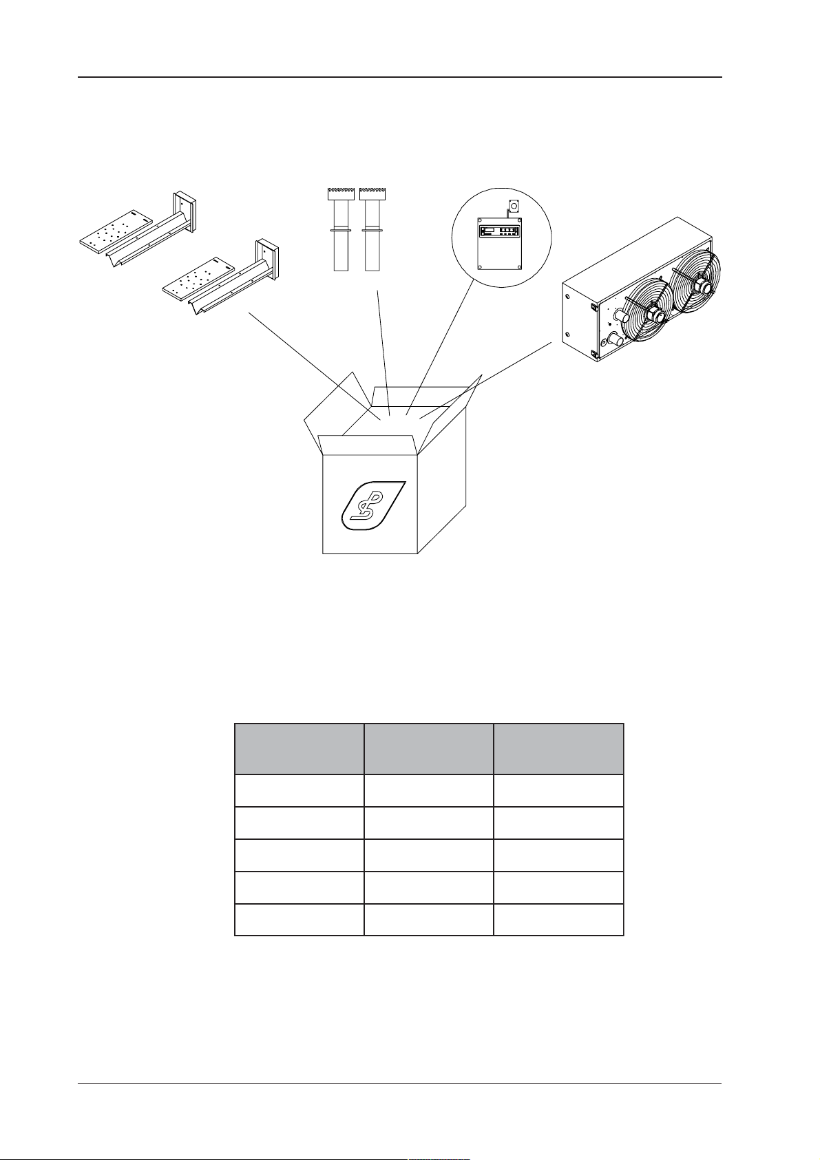
2 PACKAGING
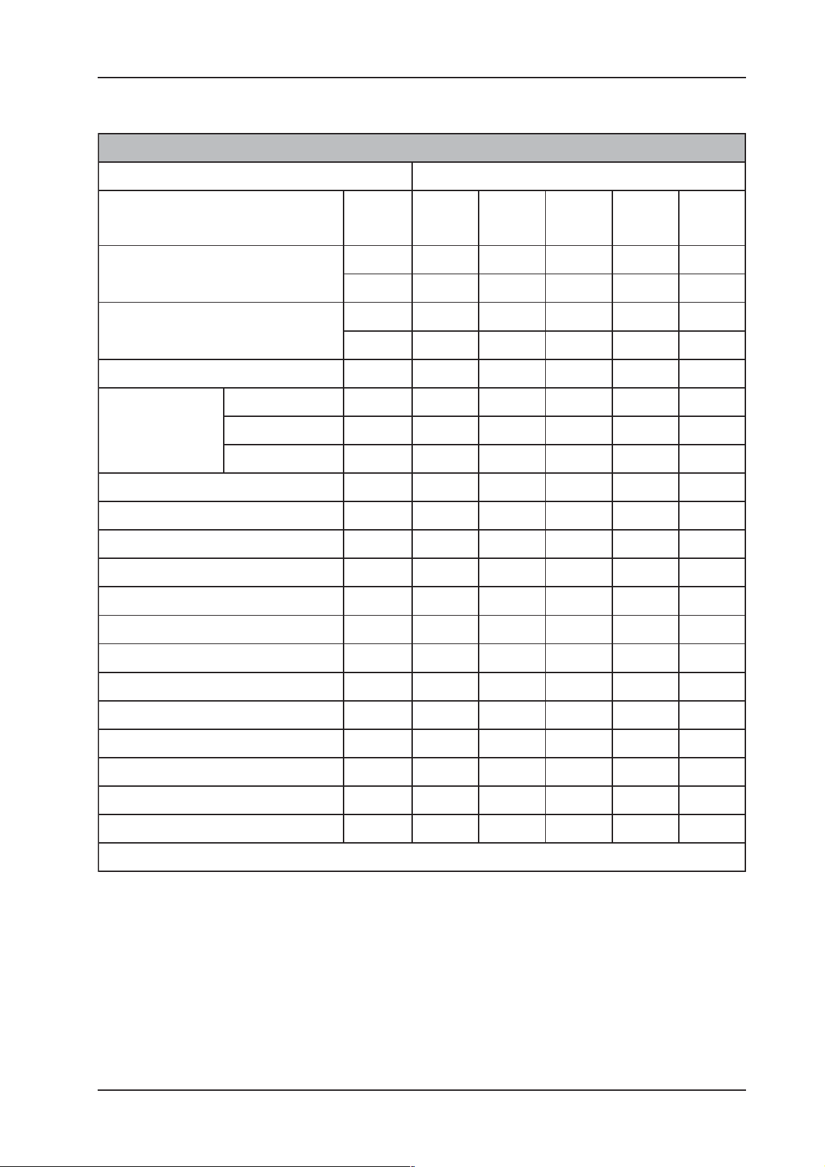
2.1 List of packing
a) The appliance complete with all its parts is delivered packed and wrapped in a protective nylon film
inside which the following are also found: the wall-mounting brackets, the electric control board
with relevant thermostat with probe (if requested) and two air/fume terminations (if requested).
5
Rev. 10EE0112
Page 6
SYSTEMA S.p.A.
Gas airtight suspended warm air heaters - EOLO
Fig.1 Appliance Packing
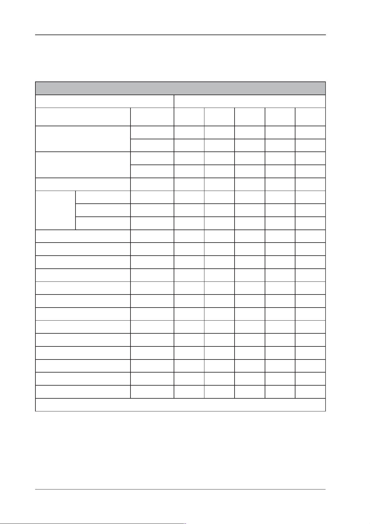
ledoM
EAseireS
]gk[
02OLOE5,7798
03OLOE5,411231
05OLOE5,051371
07OLOE8,761391
09OLOE8,891922
CAseireS
]gk[
Rev. 10EE0112
6
Page 7

Gas airtight suspended warm air heaters - EOLO
SYSTEMA S.p.A.
3 GENERAL TECHNICAL SPECIFICATIONS
3.1 Description and operating specifications
EOLO suspended gas warm air heater is composed of a combustion chamber in stainless steel,
inside which a gaseous component (natural gas or LPG) is combusted. In just a few minutes the
external surfaces of the combustion chamber and fume tube nest, lapped by ambient air circulated by
the fans, reach their operating temperature.
The appliance operates automatically; the systems for electronic control, mixing, combustion, ignition,
suction of combustion air and discharge of fumes are housed in a compartment provided with an
inspection hatch that makes adjustment and maintenance operations easy to perform. A fan-limit
safety bi-thermostat controls start-up and shut-down of the fan unit, also shutting down the burner in
the case in which the supply air temperature exceeds the safety values permitted.
Suction of combustion air and discharge of fumes can be conveyed directly outside the building (type
C appliance); therefore, there is no communication between the combustion chamber and the indoor
environment (this guarantees maximum safety).
In the summer the fan unit can be operated alone to provide ambient comfort and provide a supply of
fresh air. To switch to this operation press the button on the aluminium front of the bi-thermostat.
7
Rev. 10EE0112
Page 8
SYSTEMA S.p.A.
3.2 Technical specifications
3.2.1 Suction series with axial fans
Gas airtight suspended warm air heaters - EOLO
SNAFLACILEHHTIWSEIRESRIA-DEKCUS
SLEDOM
NOITPIRCSED
tupnilamrehtdetaR
tuptuolamrehtdetaR
ecnamofrepnoitsubmoC%8,0901,099,192,984,98
XAM
-ITPMUSOC
C°51(NO
52.3101
)rabm
retemaidrotcennocleuFsehcni"4/3"4/3"4/3"4/3"4/3
retemaidteltuoemuFmm08001001001001
retemaidekatnImm08001001001001
noitatnemilanoisneTzH/V05/03205/03205/03205/03205/032
02GsaglarutaNh/cmN33,206,317,514,759,9
03GnatuBPGLh/gk37,186,262,425,514,7
13GnaporPPGLh/gk17,246,202,444,503,7
deriuqerrewopcirttelelatoTW502042593075085
fotinU
tnemerusaem
(h/lacK iH )029.81042.92044.64002.06048.08
(Wk iH )2243450749
(h/lacK iH )971.71543.62876.24896.35172.27
(Wk iH )0213052648
EA02EA03EA05EA07EA09
yticapacriadetaerTh/cm059.1000.3005.4009.5009.6
worhtriAm0151026292
pmujlamrehTC°8282030343
rewoPW581561003574553
snoituloveR'n044.1004.1044.10931044.1
srotalitnevfo.oN°n 11223
)m5ta(leveldnuoS)A(bd0586948556
sdioPgk5,775,4115,0518,7618,891
naflacileh=E;nafria-dekcus=A
Rev. 10EE0112
8
Page 9
Gas airtight suspended warm air heaters - EOLO
3.2.2 Suction series with centrifugal fans
fotinU
NOITPIRCSED
yticapaclamrehT
Wk )iH( 2243450749
rewoplamrehtlufesU
Wk )iH( 0213052648
ycneiciffenoitsubmoC%8,0901,099,192,984,98
-erusaem
tnem
h/lacK )iH( 029.81042.92044.64002.06048.08
h/lacK )iH( 971.71543.62876.24896.35172.27
SYSTEMA S.p.A.
SNAFLAGUFIRTNECHTIWSEIRESNOITCUS
SLEDOM
CA02CA03CA05CA07CA09
NOITPMUSOCXAM
52.3101C°51(
)rabm
sgnilpuocleufforetemaiDsehcnI"4/3"4/3"4/3"4/3"4/3
retemaidegrahcsidemuFmm08001001001001
retemaidnoitcuSmm08001001001001
egatlovylppuSzH/V05/03205/03205/03205/03205/032
rewopdebrosbalatoTW0720560080380081
yticapacriadetaerTh/cm009.1051.3005.4007.5006.8
erusserplatoT
daehlamrehTC°9272031372
rewop)s(naFW052575007537075.1
snoituloveR'n009009009009009
snafforebmuN°n 11223
)m5ta(.ldnuoS)A(bd5426544506
02GsaglarutaNh/cmN33,206,317,514,759,9
03GenatuBGPLh/gk37,186,262,425,514,7
13GenaporPGPLh/gk17,246,202,444,503,7
Hmm
O
2
2101112101
thgieWgk98231371391922
naflagufirtnec=Crenrubrianoitcus=A
Category..........................II
2H3+
9
Rev. 10EE0112
Page 10

SYSTEMA S.p.A.
Gas airtight suspended warm air heaters - EOLO
3.3 Main control and safety components on the appliance
a) Electronic control unit: one for all models. This controls opening of the gas solenoid valve and
ignition of the burner. After receiving the electrical signal from the ambient thermostat, it checks
that the pressure switch is operating normally (ignition is not enabled unless this check is passed).
It then enables prewash of the combustion chamber (4 exchanges) and then ignition by means of
a spark. If the flame is not detected (ionization probe) within the safety time the appliance shuts
down. To restart it wait a few seconds and press the specific reset button with LED on the control
board.
CONTROL UNIT TECHNICAL SPECIFICATIONS
Make ............................................................ BRAHMA ........................BRAHMA
Mod .............................................................. CM 31 F .......................... CM 32 F
Supply voltage .............................................. 220/240 V 50/60 Hz ....... 220/240 V 50/60 Hz
Utilization temperature .................................. de -20 °C à + 60°C ......... de -20 °C à + 60°C
Prewash time ............................................... 20 sec ............................. 20 sec
Safety time at start-up .................................. max 10 sec ..................... max 10 sec
Safety time at shut-down .............................. < 1sec............................. < 1 sec
b) Differential pressure switch: the aim of this is to interrupt operation of the appliance if the flow rate
of the fan-exhaust fan is insufficient caused either by a fault in the fan or by clogging in the combustion
circuit (combustion air duct, combustion chamber, heat exchanger, combustion products discharge),
both of which can be caused by bad combustion CO forming above the permitted limits. This is
located inside the compartment which houses all the control components, and detects, by means
of two silicone tubes, both the pressure in the combustion air suction duct and the pressure inside
the burner box in which the combustion torch is located. The difference between the two pressure
values with the exhaust fan operating is the control signal for safe and correct combustion.
PRESSURE SWITCH SPECIFICATIONS
Make ..................................................................................................... HUBA CONTROL
Code ...................................................................................................... 605.99501
Assembly position ................................................................................. vertical
Max. working pressure .......................................................................... 5000 Pa
Reset point (opening) ............................................................................ 110 Pa (+/- 16 Pa)
Pneumatic connection ...........................................................................Ø 6,2 mm
Utilization temperature ...........................................................................-30°C, +85°C
c) Gas valve: this is multifunction and multigas with double safety solenoid valve (connected in series)
in class B. Provided with a pressure regulator, slow ignition device and gas filter. Located on the
aluminium body are the threaded gas inlet-outlet connection ½ RP UNI-ISO 7, with relevant pressure
inlet and outlet. Gas valve adjustment and the only maintenance operation that can be performed
on the valve (replacement of the coils) must only be executed by qualified technicians.
GAS VALVE TECHNICAL SPECIFICATIONS
Make ..................................................................................................... SIT CONTROLS
Mod. ...................................................................................................... 830 TANDEM
Supply voltage .......................................................................................220/240 V 50/60 Hz
Degree of electrical protection ...............................................................IP 54
Closing time .......................................................................................... < 1s
Utilization temperature ...........................................................................0° ÷ +60 °C
-20° ÷ +60 °C (on request)
Range of output pressure ......................................................................3 ÷ 50 mbar
Rev. 10EE0112
10
Page 11

Gas airtight suspended warm air heaters - EOLO
d) Fan-limit safety bi-thermostat with automatic reset: this has a double aim:
-to control start-up of the fans after the air has reached 50°C and shut-down of these when the air
temperature has dropped below 30°C;
-to interrupt operation of the appliance if there is abnormal overheating of the air (>90°C); the appliance
can be reset manually using the reset button located on the board.
SAFETY BI-THERMOSTAT TECHNICAL SPECIFICATIONS
Limit control ...........................................................................................4 (4) A
Fan control ............................................................................................ 7 (7) A
Supply voltage ....................................................................................... 230-240 V
SYSTEMA S.p.A.
11
Rev. 10EE0112
Page 12
SYSTEMA S.p.A.
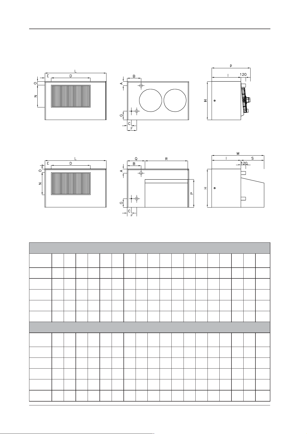
3.4 Overall dimensions
SERIES AE with axial fan
Front view Rear view Side view
SERIES AC with centrifugal fan
Gas airtight suspended warm air heaters - EOLO
Front view Rear view Side view
Fig.2 Overall dimensions
SEIRESLAIXASNOISNEMIDLLAREVO
A
B
C
D
E
F
G
H
I
L
M
N
O
P
Q
R
SLEDOM
EA0257158154005245020125660040780030310255,77
EA03502032350376213120020075840711083001056511
EA050015435010395715325120085550451083001527151
EA070015435010395715325120085550451083001527861
EA0903304300104210610425120085550381083001527991
SLEDOM
CA02571581540052450201256600407802800303106559307408398
CA03502032350376213120020075840711599083001046623068015231
]mm[
]mm[
]mm[
]mm[
]mm[
]mm[
]mm[
]mm[
]mm[
]mm[
]mm[
]mm[
]mm[
]mm[
]mm[
SEIRESLAGUFIRTNECSNOISNEMIDLLAREVO
A
B
C
D
E
F
G
H
I
L
M
N
O
P
Q
]mm[
]mm[
]mm[
]mm[
]mm[
]mm[
]mm[
]mm[
]mm[
]mm[
]mm[
]mm[
]mm[
]mm[
]mm[
S
]mm[
]mm[
R
S
]mm[
]mm[
thgieW
]gk[
thgieW
]gk[
CA05001543501039571532512008555045156010830015574440011015371
CA07001543501039571532512008555045156010830015574440011015391
CA090330430010421061042512008555038156010830015570840041015922
Rev. 10EE0112
12
Page 13
Gas airtight suspended warm air heaters - EOLO
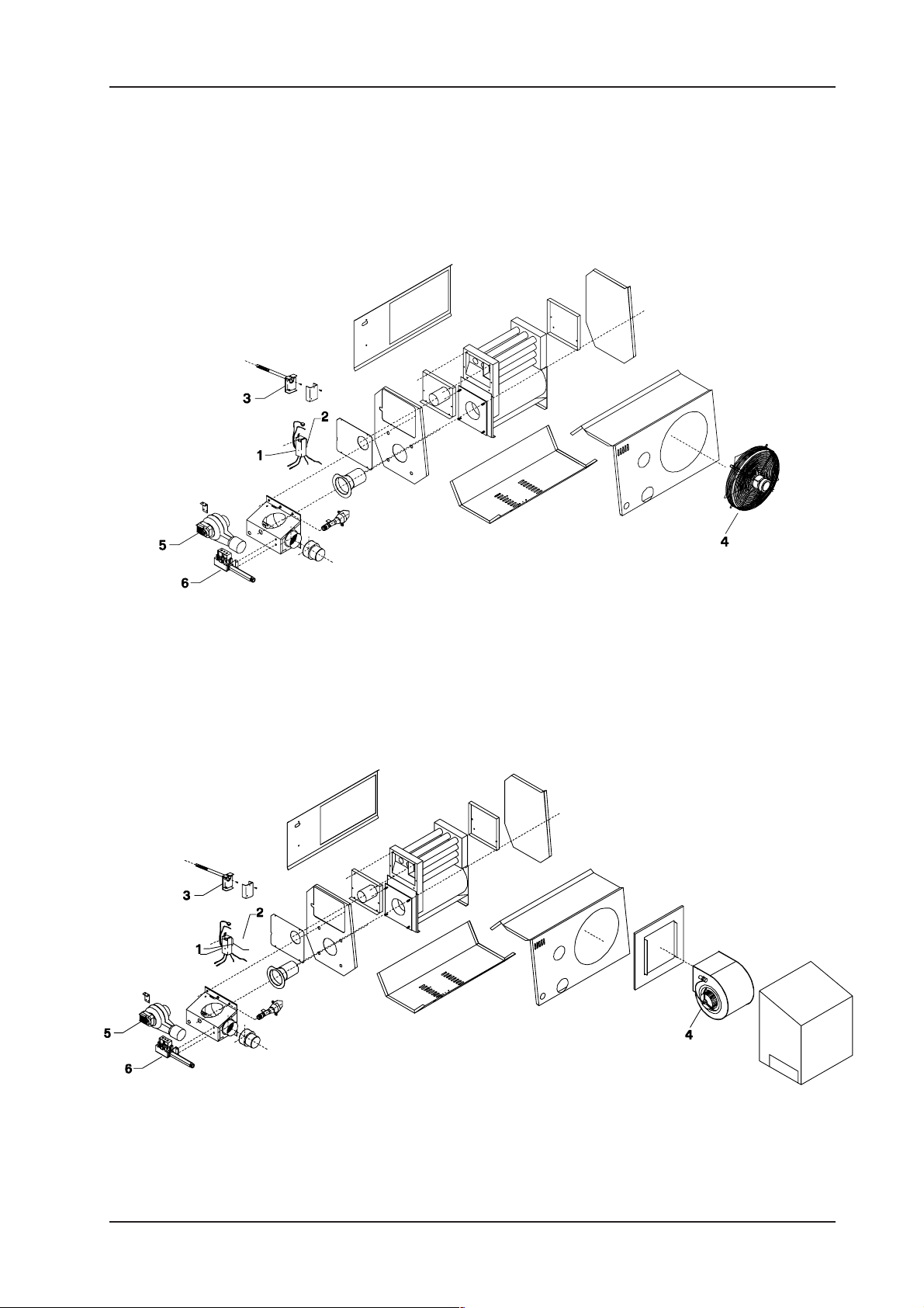
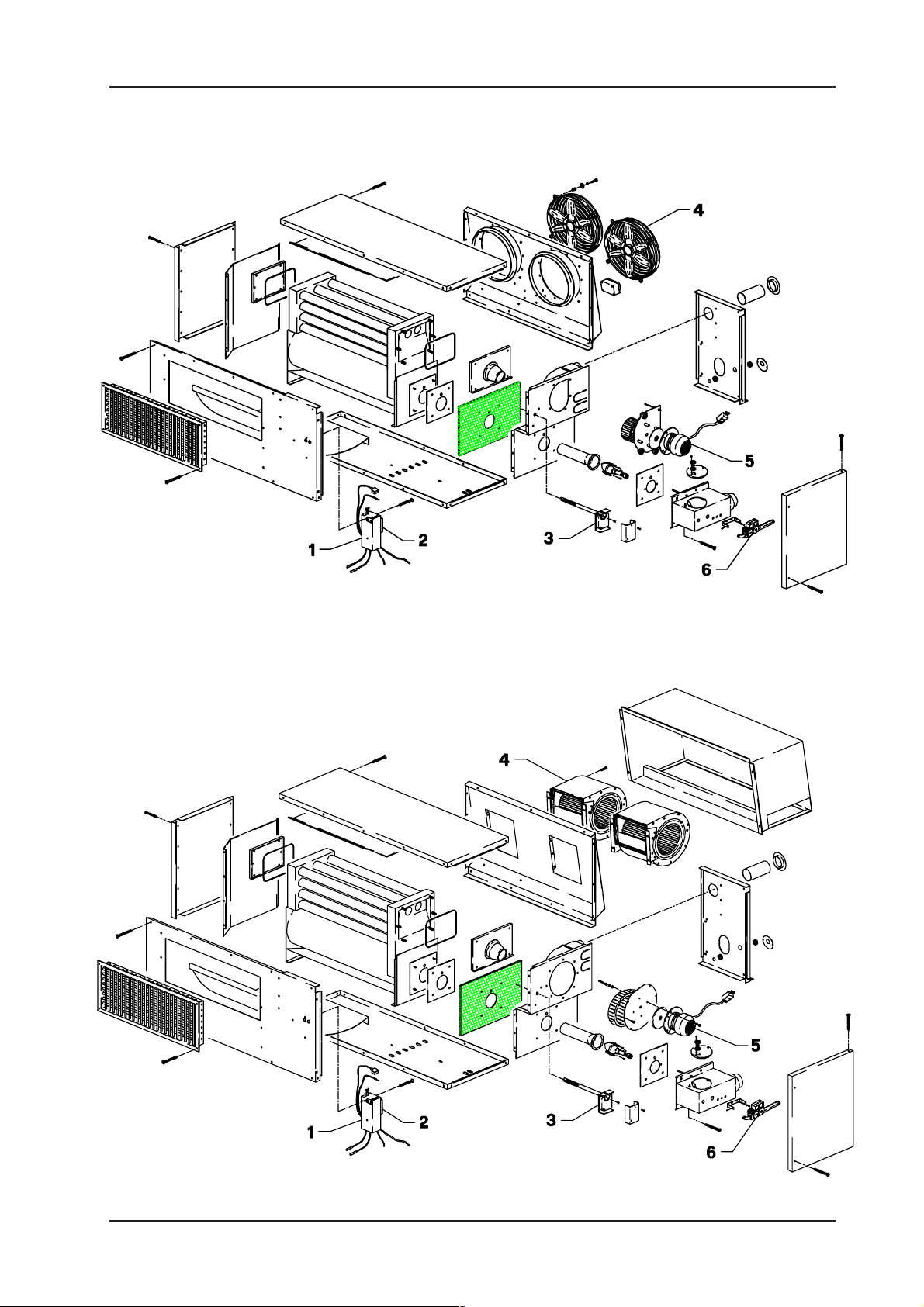
3.5 Exploded view of Eolo heaters
3.5.1 Exploded view of Eolo20AE
SYSTEMA S.p.A.
Fig. 3 Exploded view of EOLO20AE
3.5.2 Exploded view of Eolo20AC
Fig. 4 Exploded view of EOLO20AC
13
Rev. 10EE0112
Page 14
SYSTEMA S.p.A.
3.5.3 Exploded view of Eolo30AE
Gas airtight suspended warm air heaters - EOLO
Fig.5 Exploded view of EOLO30AE
3.5.4 Exploded view of Eolo30AC
Rev. 10EE0112
Fig.6 Exploded view of EOLO30AC
14
Page 15
Gas airtight suspended warm air heaters - EOLO
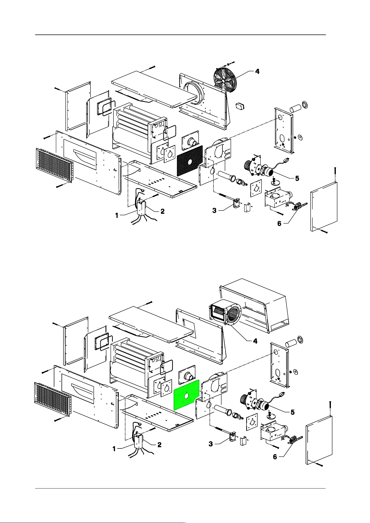
3.5.5 Exploded view of Eolo50AE-Eolo70AE
SYSTEMA S.p.A.
Fig. 7 Exploded view of Eolo50AE-Eolo70AE
3.5.6 Exploded view of Eolo50AC-Eolo70AC
Fig. 8 Exploded view of Eolo50AC-Eolo70AC
15
Rev. 10EE0112
Page 16

SYSTEMA S.p.A.
3.5.7 Exploded view of Eolo90AE
Gas airtight suspended warm air heaters - EOLO
Fig. 9 Exploded view of Eolo90AE
3.5.8 Exploded view of Eolo90AC
Rev. 10EE0112
Fig. 10 Exploded view of Eolo90AC
16
Page 17

Gas airtight suspended warm air heaters - EOLO
SYSTEMA S.p.A.
3.5.9 Legend of components
.SOP EDOC NOITPIRCSED YT.Q .SOP EDOC NOITPIRCSED YT.Q
EA02OLOESTNENOPMOCFODNEGEL CA02OLOESTNENOPMOCFODNEGEL
1
2
3
4
5
6
0100PAEC10F13MCTINULORTNOC
8011RPEC40
1400IBEC40TATSOMREHT-IBYTEFASTIMIL-NAF
9080EVEC40
4003SAEC20
7350VEEC20MEDNAT038TISEVLAVDIONELOS
ABUHHCTIWSERUSSERPRIA
aP011-506.DOMSLORTNOC
004E6A
SEEMUFRUETARIPSARUETOM
C2/002VEINILATAN
11
12
13
MBE-LHEIZLADIOCILEHRUETALITNEV
14
15
16
EA03OLOESTNENOPMOCFODNEGEL CA03OLOESTNENOPMOCFODNEGEL
1
2
3
4
5
6
0100PAEC10F13MCTINULORTNOC
8011RPEC40
1400IBEC40TATSOMREHT-IBYTEFASTIMIL-NAF
9080EVEC40004E4AMBE-LHEIZNAFLAIXA
4003SAEC20
7350VEEC20MEDNAT038TISEVLAVDIONELOS
11
ABUHHCTIWSERUSSERPRIA
aP011-506.DOMSLORTNOC
12
13
14
INILATANROTOMNAFTSUAHXEEMUF
C2/002VE
15
16
EA05OLOESTNENOPMOCFODNEGEL CA05OLOESTNENOPMOCFODNEGEL
1
2
3
4
5
6
0100PAEC10F13MCTINULORTNOC
8011RPEC40
1400IBEC40TATSOMREHT-IBYTEFASTIMIL-NAF
9080EVEC40004E4AMBE-LHEIZNAFLAIXA
7820TMEC00
7350VEEC20MEDNAT038TISEVLAVDIONELOS
ABUHHCTIWSERUSSERPRIA
aP011-506.DOMSLORTNOC
.A.RW001
11
12
13
24
LEMISROTOMNAFTSUAHXEEMUF
15
16
EA07OLOESTNENOPMOCFODNEGEL CA07OLOESTNENOPMOCFODNEGEL
1
2
3
4
5
6
4670PAEC10F23MCTINULORTNOC
8011RPEC40
1400IBEC40TATSOMREHT-IBYTEFASTIMIL-NAF
0180EVEC40054E4AMBE-LHEIZNAFLAIXA
7280TMEC00
7350VEEC20MEDNAT038TISEPAPUOS
ABUHHCTIWSERUSSERPRIA
aP011-506.DOMSLORTNOC
.A.RW001
11
12
13
24
LEMISROTOMNAFTSUAHXEEMUF
15
26
EA09OLOESTNENOPMOCFODNEGEL CA09OLOESTNENOPMOCFODNEGEL
1
2
3
4
5
6
4670PAEC10F23MCTINULORTNOC
8011RPEC40
1400IBEC40TATSOMREHT-IBYTEFASTIMIL-NAF
9080EVEC40004E4AMBE-LHEIZNAFLAIXA
1062OMEC40
7350VEEC20MEDNAT038TISEVLAVDIONELOS
ABUHHCTIWSERUSSERPRIA
aP011-506.DOMSLORTNOC
.O.RW081
11
12
13
34
LEMISROTOMNAFTSUAHXEEMUF
15
26
0100PAEC10F13MCTINULORTNOC
8011RPEC40
1400IBEC40TATSOMREHT-IBYTEFASTIMIL-NAF
7790EVEC40
4003SAEC20
7350VEEC20MEDNAT038TISEVLAVDIONELOS
0100PAEC10F13MCTINULORTNOC
8011RPEC40
1400IBEC40TATSOMREHT-IBYTEFASTIMIL-NAF
7790EVEC40
4003SAEC20
7350VEEC20MEDNAT038TISEVLAVDIONELOS
0100PAEC10F13MCTINULORTNOC
8011RPEC40
1400IBEC40TATSOMREHT-IBYTEFASTIMIL-NAF
7790EVEC40
7820TMEC00
7350VEEC20MEDNAT038TISEVLAVDIONELOS
0100PAEC10F23MCTINULORTNOC
8011RPEC40
1400IBEC40TATSOMREHT-IBYTEFASTIMIL-NAF
7790EVEC40
7280TMEC00
7350VEEC20MEDNAT038TISEVLAVDIONELOS
0100PAEC10F23MCTINULORTNOC
8011RPEC40
1400IBEC40TATSOMREHT-IBYTEFASTIMIL-NAF
7790EVEC40
1062OMEC40
7350VEEC20MEDNAT038TISEVLAVDIONELOS
7/9ADEPYT513317.DOC
C2/002VE
8/01ADEPYT653317.DOC
C2/002VE
7/9ADEPYT713317.DOC
.A.RW001.TOM
8/01ADEPYT653317.DOC
.A.RW001
8/01ADEPYT653317.DOC
.O.RW081
1
ABUHHCTIWSERUSSERPRIA
aP011-506.DOMSLORTNOC
1
1
ITAROZRAMNAFLAGUFIRTNEC
1
INILATANROTOMNAFTSUAHXEEMUF
1
1
1
ABUHHCTIWSERUSSERPRIA
aP011-506.DOMSLORTNOC
1
1
ITAROZRAMNAFLAGUFIRTNEC
1
INILATANROTOMNAFTSUAHXEEMUF
1
1
1
ABUHHCTIWSERUSSERPRIA
aP011-506.DOMSLORTNOC
1
1
ITAROZRAMNAFLAGUFIRTNEC
2
LEMISROTOMNAFTSUAHXEEMUF
1
1
1
ABUHHCTIWSERUSSERPRIA
aP011-506.DOMSLORTNOC
1
1
ITAROZRAMNAFLAGUFIRTNEC
2
LEMISROTOMNAFTSUAHXEEMUF
1
2
1
ABUHHCTIWSERUSSERPRIA
aP011-506.DOMSLORTNOC
1
1
ITAROZRAMNAFLAGUFIRTNEC
3
LEMISROTOMNAFTSUAHXEEMUF
1
2
17
Rev. 10EE0112
Page 18

SYSTEMA S.p.A.
Gas airtight suspended warm air heaters - EOLO
3.6 Position of the ignition and detection electrodes
Fig. 11 Position of electrodes
3.7 Position of the nozzle
Fig. 12a Position of nozzles
Rev. 10EE0112
Fig. 12b Position of nozzles - second flame level
(Eolo 70 AE/AC, Eolo 90 AE/AC)
18
Page 19

Gas airtight suspended warm air heaters - EOLO
SYSTEMA S.p.A.
4 INSTALLATION
4.1 Place of installation and safety distances
To obtain the maximum yield from EOLO suspended warm air heaters the following rules should be followed:
- Establish the position, bearing in mind the type of work, priority zones to be heated and absorbing walls
(windows, doors, entrances etc.) see fig. (11a, 11b, 11c).
- Install the appliances respecting the correct
distances from the walls see. fig. ( 11d,11e)
- Install the EOLO suspended heaters as near
as possible to the zone to be heated complying with a distance from the floor and from
people to ensure the jet of warm air is not
aimed directly at them.
- When positioning the EOLO suspended
heaters take into account any obstacles, such
as shelves, walls, columns, etc..
- If several appliances are to be installed in the
same environment, it is advisable to position
these on opposite walls and between one
another to cover the area to be heated
uniformly.
- If there are any drafts of cold air from
entrances, doors, etc., it is advisable to install
the appliances so that the jet of hot air is aimed
towards the source of cold air.
- Appliances must never be installed in niches
or positions that do not guarantee sufficient
aeration for correct operation.
- Several appliances installed in the same room
or in directly communicating rooms, are
considered as a single system, with a thermal
capacity of the total of the thermal capacities
of each single appliance.
- In environments subjected to vacuum
pressures or in which processes develop a
noteworthy amount of non-combustible dust,
the appliances must be installed so that air
suction and discharge of fumes is performed
directly from the outside through the outside
wall (or aperture) of the room in which the
appliances are installed.
- Installation must be performed by
professionally qualified personnel responsible
for complying with the current safety
standards. The manufacturer declines all responsibility in the case of damages caused
by erroneous installation or improper and/or incorrect use of the appliance.
Fig.11a
Fig.11d
Fig.11b
Fig.11c
Fig.11e
N.B. Make sure that rooms are specifically ventilated for type B applications
19
Rev. 10EE0112
Page 20

SYSTEMA S.p.A.
4.2 Installing the appliance
4.2.1 Fitting the brackets for Eolo 20
Gas airtight suspended warm air heaters - EOLO
1= Bracket to be fixed to the wall
2= Bracket to be fixed under Eolo
3= Supporting bracket
Rev. 10EE0112
Fig. 13 Fixing brackets for Eolo20
20
Page 21

Gas airtight suspended warm air heaters - EOLO
4.2.2 Fitting the brackets for Eolo 30-50-70-90
SYSTEMA S.p.A.
Holes for fixing the plate
under Eolo
Slots for fixing the plate (1) to
the bracket (2)
1
2
Holes for Eolo series
AE
Holes for Eolo series AC
1) Fix the two plates (1) under
Eolo with the corresponding
holes.
2) Fix the two brackets (2) to the
wall complying with the
distance of the plates (1) fixed
under Eolo.
3) Fix Eolo using the two slots on
the plates to the wall-mounted
brackets (2); for Eolo AC the
fixing holes are those farthest
from the wall.
1
2
Fig.14 Fitting the brackets Eolo 30/50/70/90
21
Rev. 10EE0112
Page 22

SYSTEMA S.p.A.
4.3 Fitting the fire damper (optional)
Gas airtight suspended warm air heaters - EOLO
Rev. 10EE0112
Fig. 15 Fitting the fire damper
22
Page 23

Gas airtight suspended warm air heaters - EOLO
5 SETTING UP THE APPLIANCE
5.1 Examples of applications
IMPORTANT!!
The heater may be installed outdoors with temperatures down to -15°C. Below this
temperature operation of the appliance is no longer guaranteed.
SYSTEMA S.p.A.
Fig. 16 Examples of application
For the examples of applications shown above, the company Systema only provides the main components,
namely the heater with original air outlets and adjustable fins, fire damper, original filters, supporting brackets,
fume termination. All other components required to perform complete application, namely air pipe fittings,
intake and external air regulation shutters, covers, cooling batteries, etc., must be identified by the installing
company.
LEGEND
1= Pipe
2= Dielectric joint
3= Manual on-off valve in an easy to reach
position
4= Gas feed pipe
5= Supporting bracket
6= Vibration damping joint
7= Manual gas on-off valve
8= Combustion air inlet termination
9= Combustion products outlet termination
10= Heater
11= Two-way fire damper
12= Distribution outlet
13= Protective canopy
14= External perimeter wall
15= Centrifugal fan
16= Control board with ambient thermostat
23
Rev. 10EE0112
Page 24

SYSTEMA S.p.A.
Gas airtight suspended warm air heaters - EOLO
6 DISCHARGE AND SUCTION DUCTS
The fume discharge ducts relevant to type C appliances with natural or forced draft, must comply with
the following conditions:
they must be metal, be constructed in materials resistant to normal mechanical stress,
heat and the action of combustion products and any condensation through time; the use of
corrugated ducting is not permitted.
It is possible to use both rigid pipe in stainless steel and in aluminium (the latter with a minimum
thickness of 1.5 mm).
As a connection it is possible to utilize double wall flexible stainless steel pipe with a smooth internal
surface (previously subjected to testing according to EN 166/21).
For combustion air ducts to the burner any kind of metal pipe can be used.
(1)
ventilated for type B applications
(1) Make sure that rooms are specifically
(1)
Fig. 17 Lengths of fume and combustion air ducts
For fume ducts over 5-6 m in length, bear in mind that condensation phenomena could occur
inside the ducts if these are not sufficiently insulated.
Rev. 10EE0112
24
Page 25

Gas airtight suspended warm air heaters - EOLO
6.1 Coaxial roof discharge for Eolo20 (type C32)
SYSTEMA S.p.A.
Fig. 18 Example of coaxial roof discharge for Eolo20
1= Female coupling Ø100 mm
2= Tandem connection
3= Rigid component Ø 80 mm M/M length 320
mm
4= Elbow bend 90° Ø 80 mm F/F
5= Rigid component Ø 80 mm M/F length 125 mm
6= Eolo20
7= Elbow bend 90° Ø 80 mm M/F
8= Gasket
9= Rigid component Ø 100 mm M/F length 1.000
mm
10= Rigid component Ø 60 mm M/F length 1.000
mm
11= Reduction
12= Ceiling termination
25
Rev. 10EE0112
Page 26

SYSTEMA S.p.A.
Gas airtight suspended warm air heaters - EOLO
6.2 Coaxial wall discharge for Eolo20 (type C12)
Fig. 19 Example of coaxial wall discharge for Eolo20
1= Rigid component Ø 80 mm M/F length 250 mm
2= Gasket
3= Female coupling Ø 100 mm
4= Hole flange
5= Coaxial wall termination
6= Tandem connection
7= Elbow bend 90° Ø 80 mm M/F
8= Eolo20
Rev. 10EE0112
26
Page 27

Gas airtight suspended warm air heaters - EOLO
6.3 Separate wall discharge for Eolo20 (type C12)
SYSTEMA S.p.A.
Fig. 20 Example of coaxial wall discharge for Eolo20
1= Rigid component Ø 80 mm M/F length 1000 mm
2= Hole flange
3= Cover for fume discharge termination
4= Cover for air termination
5= Eolo20
27
Rev. 10EE0112
Page 28

SYSTEMA S.p.A.
Gas airtight suspended warm air heaters - EOLO
6.4 Coaxial roof discharge for Eolo30-50-70-90 (type C32)
Fig. 21 Example of coaxial roof discharge for Eolo30/50/70/90
1= Coaxial roof termination Ø 150/100 mm
2= Top collar
3= Lead flashing
4= Hole flange
5= Tandem connection
6= Clamping band
Rev. 10EE0112
7= Elbow bend 90° Ø 100 mm M/F
8= Silencer
9= Eolo
10= Band for clamping flexible air pipe
11= Flexible pipe for combustion air
28
Page 29

Gas airtight suspended warm air heaters - EOLO
SYSTEMA S.p.A.
6.5 Coaxial wall discharge for Eolo30-50-70-90 (type C12)
Fig. 22 Example of coaxial wall discharge for Eolo30/50/70/90
1= Silencer
2= Clamping band
3= Tandem connection
4= Coaxial wall termination Ø 150/100 mm
5= Hole flange
6= Band for clamping flexible air pipe
7= Flexible pipe for combustion air
8= Eolo
29
Rev. 10EE0112
Page 30

SYSTEMA S.p.A.
Gas airtight suspended warm air heaters - EOLO
6.6 Separate wall discharge for Eolo30-50-70-90 (type C12)
Fig. 23 Example of separate wall discharge for Eolo30/50/70/90
1= Silencer
2= Clamping band
3= Wall fume termination Ø 100 mm
4= Wall air termination Ø 100 mm
5= Hole flange
6= Eolo
Rev. 10EE0112
30
Page 31

Gas airtight suspended warm air heaters - EOLO
SYSTEMA S.p.A.
6.7 Separate roof discharge for Eolo30-50-70-90 (type C32)
D= minimun 50 cm
Fig. 24 Example of separate roof discharge for Eolo30/50/70/90
1= Roof fume termination Ø 100 mm
2= Top collar
3= Lead flashing
4= Hole flange
5= Clamping band
6= Silencer
7= Elbow bend 90° Ø 100 mm M/F
8= Eolo
9= Rigid component Ø 100 mm M/F length 500
mm
10= Roof air termination Ø 100 mm
31
Rev. 10EE0112
Page 32

SYSTEMA S.p.A.
Gas airtight suspended warm air heaters - EOLO
7 GAS PIPES
7.1 Connecting the appliance
The gas supply pipe must be executed in compliance with the regulations in force in the country in
which the system is installed.
The sizes of the pipes and any pressure reducers must guarantee correct operation of appliances.
Materials used must conform to regulations in force in the country in which the system is installed.
a) The appliance must not be subjected to pressures exceeding 40 mbar (0.04 bar); otherwise the
membrane of the gas valve may break.
b) For natural gas: on the main line upstream, below the meter, always install a pressure stabiliser and
a gauge with a scale of 0÷60 mbar (0.06 bar) and adjust the pressure to 20 mbar (0.02 bar); higher
pressure can be the cause of bad combustion and difficulty in flame ignition.
c) For LPG (butane-propane) gas: a stage 1 pressure reducer must be installed near the tank in
order to reduce the pressure to 1.5 bar; on the main outside line beside the building always install
a stage 2 pressure reducer to reduce the pressure to the values indicated in the table on page 39.
Below the stage 2 reducer install a gauge with a scale of 0÷60 mbar (0.06 bar) and adjust the
pressure to the values indicated in the table on page 39; higher pressure can be the cause of poor
combustion and difficulty in flame ignition.
d) Upstream and downstream of the main gas supply line a gauge must be installed in a visible
position with a scale of 0÷60 mbar (0.06 bar) to check any differences upstream and downstream,
thus checking the flow rate of the entire mains.
e) Moreover, by closing the main gate valve and switching off all the appliances, the seal of the
system and gas valves can be checked by determining whether after a short period there is any
reduction in pressure on the gauges.
f) Always connect appliances using ball valve and anti-vibrating flexible joint for gas.
g) Adjusting the gas supply pressure: all appliances are inspected and regulated in the factory for the
pressures for which they are predisposed (see ratings plate on the burner or table on page 39).
IMPORTANT
For natural gas supply with pressures above 20 mbar (200 mm c.a.), always fit a pressure
stabiliser for each appliance and adjust the pressure to 20 mbar.
Rev. 10EE0112
32
Page 33

Gas airtight suspended warm air heaters - EOLO
SYSTEMA S.p.A.
8 ELECTRICAL SYSTEM
8.1 Connection diagram to CE type boards mod. 04CEQU1202
(without timer) and mod. 04CEQU1203 (with timer)
All electrical connection must be performed in compliance with the regulations in force in the country in
which the system is installed.
Refer to the wiring diagram given in this manual to connect the control board to the appliance.
In particular:
a) Use an electrical cable with no. 8 wires, for phase, neutral, earth, appliance reset, operating
telltale, shut-down telltale and ambient thermostat.
b) Check that it is accurately earthed and comply with the phase and neutral connections; otherwise
the series CE control board will break.
c) Position the ambient thermostat at a height of 1.5 1.8 m from the ground.
Fig. 25 Connection to the series CE board
33
Rev. 10EE0112
Page 34

SYSTEMA S.p.A.
Gas airtight suspended warm air heaters - EOLO
8.2 Connection to the board code 04CEQU1204
Fig. 26a Connection to the board code 04CEQU1204 (with 11 terminal)
Rev. 10EE0112
Fig. 26b Connection to the board code 04CEQU1204 (with 5 terminal)
34
Page 35

Gas airtight suspended warm air heaters - EOLO
8.3 Internal wiring diagram Eolo 20-30-50
SYSTEMA S.p.A.
on the ground
To the control board
Electrical supply
1/N/PE ~ 50Hz 230V
Fig. 27 Eolo internal connection diagram with
control unit CM 31F
35
Rev. 10EE0112
Page 36

SYSTEMA S.p.A.
8.4 Internal wiring diagram Eolo 70-90
Gas airtight suspended warm air heaters - EOLO
Fig. 28 Eolo internal connection diagram
with control unit CM 32F
1/N/PE ~ 50Hz 230V
To the control board
on the ground
Electrical supply
Rev. 10EE0112
36
Page 37

Gas airtight suspended warm air heaters - EOLO
SYSTEMA S.p.A.
9 INSPECTION AND STARTING UP THE
SYSTEM
9.1 Preliminary ignition procedures
a) Check that the appliances have been set for the available type of gas (consult paragraph 10.1 on
gas conversion if required), check the mains pressure (see table below) and turn on the gas. Seal
the gas valve adjustment component after regulation.
b) Check that the electrical connection between the burner and switchboard is correct.
c) Position the ambient thermostat for the zone to the required temperature (consult the instructions
provided with the switchboard); the heaters start up.
9.2 Ignition phases
1) The gas pressure switch closes the contact of the phase line, supplying the CM 31F/32F instrument
with power; this then starts the feed procedure.
2) The fume exhaust fan then starts up, triggering the air pressure switch; at this point the instrument
checks the air pressure switch operation and if this is regular the prewash procedure in the combustion
chamber starts; this lasts for a minimum of 20 seconds. FOR FURTHER INFORMATION ON THE
INSTRUMENT REFER TO THE RELEVANT TECHNICAL NOTES.
3) After the prewash procedure, the instrument gives the ignition charge for 5 seconds and the green
telltale lights up simultaneously. If the flame does not ignite, the instrument shuts down and the red
telltale lights up. Press the reset button to restart it.
4) In models with two solenoid valves, the burner ignites at the first flame level and only after receiving
further consent by the CM 32F instrument does it operate at full power.
IMPORTANT:
If the connection S3 B4 are inverted (with electronic thermostat) = the thermostat does not switch on
and does not enable burner operation.
If T1 T2 are inverted = the shut-down telltale lights up with the burner operating.
If phase and neutral are inverted during supply = the burner ignites the flame and then shuts down (10
seconds).
If the burner is reset with the phase signal = the CM 31F/32F control unit is damaged or it will not reset.
If the thermostat is fitted to the main line = the combustion chamber is not cooled and damage is
caused to this and the fan units.
Permanent jumper on terminals S3 and B4 with the heaters switching on and off = same damage as
above.
Check electrical connections: the electrical connections listed below MUST be complied with.
37
Rev. 10EE0112
Page 38

SYSTEMA S.p.A.
Gas airtight suspended warm air heaters - EOLO
9.3 Adjusting the pressure on the solenoid valve and pressure intake
1= Slow ignition regulation
2= Pressure intake downstream
3= Flow rate regulation
4= Pressure intake upstream
5= Second flame level
Fig. 29 Solenoid valve for Eolo mods. 20-30-50 Fig. 30 Solenoid valve for Eolo mods. 70-90
N.B. Seal the adjustment component of the gas solenoid valve after regulation.
LEDOM
02GHsaglarutaN
YLPPUSSNIAM
ERUSSERP
EHTTAERUSSERP
RENRUB
RETEMAIDELZZON
NOITPMUSNOClanimoN
52,3101dnaC°51ta
rabm
03GenatuBGPL
13GenaporPGPL
02GHsaglarutaN
03GenatuBGPL
13GenaporPGPL
02GHsaglarutaN
03GenatuBGPL
13GenaporPGPL
02GHsaglarutaN
03GenatuBGPL
13GenaporPGPL
rabm
rabm
rabm
rabm
rabm
rabm
mm
mm
mm
h/³mN
h/gK
h/gK
02OLOE
CA/EA
0202020202
9292929292
7373737373
0,111,70,81,77,7
9,728,82824,725,62
3,633,63538,435,33
0,45,50,77,55,6
3,20,36,39,24,3
3,20,36,39,24,3
33,206,317,514,759,9
37,186,262,425,514,7
17,146,202,444,503,7
03OLOE
CA/EA
05OLOE
CA/EA
07OLOE
CA/EA
09OLOE
CA/EA
Rev. 10EE0112
38
Page 39

Gas airtight suspended warm air heaters - EOLO
9.4 Bi-thermostat for adjusting fan start-up
Adjustment levers
SYSTEMA S.p.A.
Automatic/manual
operation button
Fig. 31 Fan-limit bi-thermostat
During normal operation the sensor of the bi-thermostat rotates and, once the temperature set on the
set point has been reached, closes the contact that supplies power to the fan.
The bi-thermostat has a bi-metal thermostat that operates the fan within 90 seconds of being enabled.
IMPORTANT !!
When setting temperatures and using the adjustment levers, hold the housing firmly so that
it does not rotate and supply power to the sensor.
Adjustment levers
FAN OFF .......................................................................... Fan shut-down temperature
FAN ON ............................................................................ Fan start-up temperature
LIMIT OFF ........................................................................ Eolo limit shut-down temperature
Automatic/manual operation button .................................. Button for manual operation of the fan
39
Rev. 10EE0112
Page 40

SYSTEMA S.p.A.
Gas airtight suspended warm air heaters - EOLO
9.3 Measuring the efficiency
Taking a sample of combustions products:
Taking a sample of combustion products and measuring of the temperature of these must be performed
by means of the special through hole in the combustion product discharge duct.
After taking measurements, the operator must close the hole accurately to guarantee the seal of the
combustion product discharge duct during normal operation of the system.
The person in charge of operation and maintenance of the system must have the hole made by a
certified technician or service engineer, unless the heater has already been provided with a specific
hole, or one has remained following other measurements taken in compliance with the instructions
above, in conformance with the standard UNI 10389.
The hole must be located at a distance from the heater outlet equivalent to twice the internal diameter
of the combustion products discharge duct. If there is a bend in the duct inside this distance, the hole
must be located at a distance from the far end of the bend equivalent to one internal diameter of the
combustion products discharge duct.
If the concentration of CO detected in the condition of dry and air-less combustion products is
greater than 0.1% (1000 ppm) and the operator or service engineer cannot reduce it to below
this value, the combustion test must be considered as failed, notwithstanding the measured
value of combustion efficiency.
NOTE
If heat recovery systems are fitted
downstream of the heater, the
hole must be located on the
stretch of the combustion
products discharge duct below
the recover systems; this is the
case for a metal fume duct,
without insulation and located inside the room (see fig. 29a), that
provides the room with heat
either through convection and
irradiation.
B
COMBUSTION
ANALYSER
Fig. 32 Hole for taking samples for combustion analysis with
heat recovery systems (point B)
9.3.2 Measuring the temperature of combustion air
This must be performed in a suitable point of the combustion air supply duct.
After taking measurements, the operator must close the hole accurately to guarantee the seal of the
duct during normal operation of the system.
Rev. 10EE0112
40
Page 41

Gas airtight suspended warm air heaters - EOLO
SYSTEMA S.p.A.
10 MAINTENANCE
10.1 Gas conversion
The conversion must be performed by professionally qualified personnel responsible for complying
with the current safety standards. The manufacturer declines all responsibility in the case of damages
caused by erroneous conversion or improper and/or incorrect use of the appliance.
10.1.1 Conversion from Natural Gas to LPG
1) Close the gas supply and disconnect the power supply.
2) Disconnect the combustion torch from the solenoid valve EV1 (30 mm spanner).
3) Unscrew the nozzle (it has a crosswise slot on the head) from inside the torch (see fig. 12 page 18)
taking care not to damage the electrodes (ignition and flame detection) located on the head of the
torch and relevant wires.
4) Replace with the nozzle in the conversion kit after checking that the diameter corresponds to the
one given on the ratings plate.
5) Connect and clamp the torch to the solenoid valve.
6) Adjust the burner pressure with the pressure regulator of the solenoid valve, turning the screw (3)
in fig. 30 on page 38: exclude the pressure regulator of the solenoid valve by clamping the screw
(3) in a clockwise direction (+).
7) Check that the supply pressure to the burner measured at point (2) figs. 29-30 page 38, corresponds
to the ratings plate value. (*)
8) Check the gas seal on the threaded joints.
9) Affix the label (Appliance regulated for ) indicating the new type of gas to the plate provided on
the appliance.
Seal the gas valve adjustment component after regulation.
(*) For LPG (Butane G30/Propane G31) gas, a stage I pressure reducer must be installed in the
vicinity of the tank to reduce the pressure to 1.5 bar; another stage II pressure reducer must be
installed on the main outside line beside the building to reduce the pressure to the values indicated
on page 38.
On models EOLO 70/EOLO 90
Models Eolo 70 and Eolo 90 are provided with a second solenoid valve (see fig. 30 page 38).
Change the nozzle on the second solenoid valve as follows:
1) Disconnect the tube (5) from the solenoid valve EV2 (30 mm spanner), (fig. 30 page 38).
2) Unscrew the nozzle (it has a crosswise slot on the head) from inside the extension connected to the
tube (5).
3) Replace with the nozzle in the conversion kit after checking that the diameter corresponds to the
one given on the ratings plate.
4) Connect and clamp the tube (5) to the solenoid valve EV2.
5) Adjust the burner pressure with the pressure regulator of the solenoid valve, turning the screw (3)
in fig. 30 on page 38: exclude the pressure regulator of the solenoid valve by clamping the screw
(3) in a clockwise direction (+).
6) Check that the supply pressure to the burner measured at point (2) figs. 29-30 page 38, corresponds
to the ratings plate value. (*)
7) Check the gas seal on the threaded joints.
41
Rev. 10EE0112
Page 42

SYSTEMA S.p.A.
8) Affix the label (Appliance regulated for ) indicating the new type of gas to the plate provided on the
appliance.
Seal the gas valve adjustment component after regulation.
(*) For LPG (Butane G30/Propane G31) gas, a stage I pressure reducer must be installed in the
vicinity of the tank to reduce the pressure to 1.5 bar; another stage II pressure reducer must be
installed on the main outside line beside the building to reduce the pressure to the values indicated
on page 39.
Gas airtight suspended warm air heaters - EOLO
10.1.2Conversion from LPG to Natural Gas
1) Close the gas supply tap and disconnect the power supply.
2) Disconnect the combustion torch from the solenoid valve EV1 (30 mm spanner).
3) Unscrew the nozzle (it has a crosswise slot on the head) from inside the torch (see fig. 12 page 18)
taking care not to damage the electrodes (ignition and flame detection) located on the head of the
torch and relevant wires.
4) Replace with the nozzle in the conversion kit after checking that the diameter corresponds to the
one given on the ratings plate.
5) Connect and clamp the torch to the solenoid valve.
6) Adjust the burner pressure with the pressure regulator of the solenoid valve, turning the screw (3)
in fig. 30 on page 38.
7) Start up the appliance and check that the supply pressure to the burner measured at point (2) figs.
29-30 page 38 corresponds to the ratings plate value.
8) Check the gas seal on the threaded joints.
9) Affix the label (Appliance regulated for ) indicating the new type of gas to the plate provided on
the appliance.
Seal the gas valve adjustment component after regulation.
On models EOLO 70/EOLO 90
Models Eolo 70 and Eolo 90 are provided with a second solenoid valve (see fig. 30 page 38).
Change the nozzle on the second solenoid valve as follows:
1) Disconnect the tube (5) from the solenoid valve EV2 (30 mm spanner), (fig. 30 page 38).
2) Unscrew the nozzle (it has a crosswise slot on the head) from inside the extension connected to the
tube (5).
3) Replace with the nozzle in the conversion kit after checking that the diameter corresponds to the
one given on the ratings plate.
4) Connect and clamp the tube (5) to the solenoid valve EV2.
5) Adjust the burner pressure with the pressure regulator of the solenoid valve, turning the screw (3)
in fig. 30 on page 38.
6) Start up the appliance and check that the supply pressure to the burner measured at point (2) figs.
29-30 page 38, corresponds to the ratings plate value.
7) Check the gas seal on the threaded joints.
8) Affix the label (Appliance regulated for ) indicating the new type of gas to the plate provided on
the appliance.
Seal the gas valve adjustment component after regulation.
Rev. 10EE0112
42
Page 43

Gas airtight suspended warm air heaters - EOLO
10.2 Operating faults
TLUAF ESUAC YDEMER
SYSTEMA S.p.A.
rewoplartuendnaesahp)a
.detrevniylppus
noitcennochtraetneiciffusnI)b.noitcennochtraeehtkcehC)b
gulproedortcelenoitceteD)c
yltcerrocnidenoitisop
nwodstuhsdnasetingirenrubehT
.sdnoceswefaretfa
eht,pustratsrotomnaftsuahxeehT
tubnoitingistpmettanehttinulortnoc
.etingitonseodhcrotnoitsubmoceht
.ytluaf
.hctiwserusserp
tluaftnemurtsnilortnoC)dlanigirohtiwtnemurtsniecalpeR)d
sepipsagniriA)e.riaehtdeelB)e
erusserpsagtcerrocnI)fseulavehthtiwerusserpehtkcehC)f
.renrubehtotsagon)a.enilylppusehtkcehc)a
sievlavdionelosehtfoliocehT)b
riaehtfotuo-tucybdereggirtton
sievlavdionelosehtfoliocehT)c
.)launam
.!!eraps
.noitarepo
.pu-tratsgnirud
.snoitcennocehttrevnI)a
morfmm11=noitisopedortcelE)c
sihtedisnimargaidees(etalpeht
.etalpsgnitarehtno sagehtlaeS
tnenopmoctnemtsujdaevlav
.noitalugerretfa
ehtfonoitcennocehtkcehC)b
hctiwserusserpriadnaebutenocilis
eht;revirdwercsagnisutseT)c
liocehtybdetcarttasirevirdwercs
erusserpsaglarutanevissecxE)d
.elzzonehtot
.ylppusrewopon)asehctiwsehtfonoitisopehtkcehc)a
.draob
.ytluafsirotomehT)bsitifi;trapanoitareponafkcehC)b
tratstonseodnaftsuahxeemufehT
.pu
.detrevni
sag
eht,pustratsrotomnaftsuahxeehT
eht,noitingistpmettanehttinulortnoc
hcrotehttubsnepoevlavdionelos
.etingitonseod
ehttubpustratsrotomnaftsuahxeehT
otlangisehtdnestonseodtinulortnoc
.evlavdionelosdnahcroteht
.ytluafsiroticapacehT)cehthtiwroticapacahtiwecalpeR)c
.puthguacsinafrotomehT)dnafehteerF)d
eraseriwhctiwserusserpehT)e
seviecerhcrotehttahtkcehc)a
siedortcelenoitingieht)b
.yltcerrocnidenoitisop
hgihootsierusserpsagehT)c.seulavetalpgnitarehtottiteS)c
ehtgnitsetlaitinignirud)a
erusserpehtdnuoftnemurtsni
.)deulg(desolcstcatnochctiws
.ytluafsitnemurtsnilortnocehT)bnahtiwtnemurtsniehtecalpeR)b
.eraps
.snoitacificepsemas
)63.53.ppmargaid
.wensisiht
.sgnittesnoitaluger
!!erapslanigiro
.eulavetalpsgnitarehtottiteS)d
hctiwsdnadraoblortnocehtno
lanigironahtiwecalpernekorb
ees(yltcerrocseriwehttcennoC)e
fi,metsysehtmorfriaynadeelb)a
etalpehtmorfmm5tinoitisoP)b
)launamsihtnimargaidees(
htiwhctiwserusserpehtecalper)a
emasehthtiw!!erapslanigirona
43
Rev. 10EE0112
Page 44

SYSTEMA S.p.A.
Gas airtight suspended warm air heaters - EOLO
11 WARRANTY
11.1 Subject-matter and duration of the warranty
1) The Warranty is limited to faults in the material or machining of components supplied by SYSTEMA.
In the event of a fault in the material or machining, SYSTEMA shall repair or replace faulty parts exworks free of charge. ALL OTHER FORMS OF WARRANTY OR COMPENSATION, LEGAL OR
CONVENTIONAL, ARE EXPRESSLY EXCLUDED. Replaced parts shall be returned immediately
to SYSTEMA, free at its works in S. Giustina in Colle (PD), by and to the expense of the user. In the
event of operations covered by warranty, the user shall be charged the fixed call-out fee and refund
for mileage in the event of the place of the operation being over 10 kilometres from the Service
Centre.
2) The Warranty becomes valid as from Initial ignition, provided that this is performed within 6 (six)
months of the date on which the appliance is purchased by the user. In any case, the Warranty shall
expire 18 (eighteen) months from the date on which the SYSTEMA invoice is issued.
3) Any replacement of faulty parts (or the entire Appliance) shall not extend the original expiry terms
of the Warranty. The Warranty on replaced parts shall expire on the same date as the expiry date
of the Appliance Warranty.
4) The duration of the warranty shall be 1 (one) year for each component of the appliance.
11.2 Exclusions from the warranty
1) The Warranty is not valid in the case of:
a) Defects that cannot be attributed to faulty materials or machining, without limits:
- breakages during transport;
- non-compliance of the system with local laws and regulations in force;
- failure to comply with the installation instructions set down in the technical notes supplied
with the Appliance and/or the rules of correct technique;
- damage caused by accidents in general, fires or negligence that cannot be attributed to
SYSTEMA.
b) Tampering or faults due to operations performed by unauthorized personnel.
c) Defects caused by faults concerning the electrical or gas supply mains.
d) Failures caused by: incorrect maintenance, negligence or improper use, variations in the
power supply voltage, dampness and dust in the rooms, incorrect dimensioning and/or faulty
execution of installation.
e) Corrosion or breakage caused by: stray currents, condensation, overheating caused by incorrect
regulation of the pressure of supply gas or to the burner, or the use of gas with different
heating specifications than the rating plate values.
f) Use of non-original spare parts or parts not authorised by SYSTEMA.
g) Normal wear and tear.
h) Products not correctly cared for or stored.
2) Moreover, the Warranty is not valid if:
a) payment for the Appliance was not effected within the terms established in the contract.
b) Initial ignition was not effected by the Service Centre and/or its copy of the Warranty duly
compiled and signed in all parts was not received.
c) The user did not report the fault within 10 days of discovering it.
Rev. 10EE0112
44
Page 45

Gas airtight suspended warm air heaters - EOLO
SYSTEMA S.p.A.
11.3 Competence
1) Requests for operations under Warranty must be submitted, subject to forfeiture, to the Service
Centre that performed initial ignition. The user must, in this case, present the Certificate of Warranty
to the Service Centre.
2) The Service Centre shall perform operations according to its organizational requirements, during
normal working hours.
11.4 Operativeness and efficacy of the warranty
1) In order for the warranty to become operative and efficacious the user must:
a) Request the name of the Service Centre for Initial ignition from its installer.
b) Present the Service Centre personnel with the Certificate of Warranty, compile all parts of this
and ask the Service Centre to stamp and sign it in the specific spaces.
11.5 Responsibility
The customer shall exonerate the supplier from all responsibility for accidents or damages to the
machines or systems during operation. The supplier shall be liable to the purchaser only within the
limits of the warranty obligation specified above.
11.6 Legal disputes Territorial competence and rights of the parties
The Court of Padua is established as the competent court, also in the event of actions connected to or
called for by warranty. Outstanding disputes do not exonerate the customer from the obligation to
make payments, which must be made according to the contract, until the final ruling by the Judicial
Authority.
12 SETTING ASIDE
If the appliance is to be set aside for a lengthy period of time, the following operations must be performed:
Turn the master switch to 0 and disconnect the appliance from the power supply.
Close the gas supply valve and disconnect the appliance from the gas mains.
In the case of change in ownership or a new tenant, give all documents regarding the heating system
to the new owner/tenant.
IMPORTANT !!
All disconnection operations must be performed by authorised technical personnel!
45
Rev. 10EE0112
Page 46

SYSTEMA S.p.A.
13 NOTES
Gas airtight suspended warm air heaters - EOLO
Rev. 10EE0112
46
Page 47

Page 48

 Loading...