


PILOT 219 PC
INDUSTRIAL PC
INSTRUCTIONS FOR USE
PILOT
Read the instructions prior to performing any task!

© 2017
Systec & Solutions GmbH
Emmy-Noether-Straße 17
D–76131 Karlsruhe
Telephone: 0721 6644 400
Fax: 0721 6644 444
email: talk@systec-solutions.com
Internet: www.systec-solutions.com
PILOT, 1, en_US, 03.08.2017
PILOT 219 PC - Industrial PC
2

Table of contents
1 General information................................................................................... 5
1.1 Information on the user guide........................................................ 5
1.2 Copyright notice................................................................................... 5
2 Safety................................................................................................................. 7
2.1 Designated use..................................................................................... 7
2.2 Safety notices........................................................................................ 7
2.3 Important safety notes....................................................................... 8
3 Product description................................................................................. 11
3.1 Overview............................................................................................... 11
3.2 Type plate............................................................................................. 13
3.3 Technical data for the device........................................................ 14
3.4 Dimensions.......................................................................................... 16
3.5 External connections........................................................................ 17
3.5.1 Overview of external connections........................................... 17
3.5.2 Description of the external connections............................... 18
3.6 Conformity........................................................................................... 21
4 Starting up................................................................................................... 23
4.1 Unpacking the device...................................................................... 23
4.2 Setting up the device....................................................................... 23
4.3 Mounting the device........................................................................ 24
5 Operation...................................................................................................... 27
5.1 Switching the device on.................................................................. 27
5.2 Switching the device off................................................................. 27
5.3 Operating the touchscreen............................................................ 28
5.4 Cleaning the device.......................................................................... 28
5.5 Using the optional USB connection............................................ 32
5.6 Setting up the WLAN (optional) .................................................. 32
5.7 Hard disk LED (optional)................................................................. 32
6 Repairs........................................................................................................... 33
7 Storage........................................................................................................... 35
7.1 Unmounting the device.................................................................. 35
7.2 Storing the device............................................................................. 37
8 Packaging and transport...................................................................... 39
8.1 Packaging the device....................................................................... 39
8.2 Transporting the device.................................................................. 39
9 Disposal......................................................................................................... 41
10 Site information......................................................................................... 43
Table of contents
PILOT 219 PC - Industrial PC
3

Table of contents
PILOT 219 PC - Industrial PC
4

1 General information
1.1 Information on the user guide
This translation of the original user guide is an integral part of the
device and provides you with information on the set-up, use, storage
and disposal of the device.
Before beginning any work, read the user guide and always keep it in
an accessible place.
This user guide is aimed solely at authorized specialists. None of the
content of this user guide may be put to practice by anyone other than
trained specialists.
Our user guides are updated regularly. Please send us your suggested
improvements and other hints by e‑mail, phone or fax. This will help us
to ensure that our documentation is as intelligible and user-friendly as
possible.
You will find our contact information on the inside of the front cover or
under “Site information”.Ä Chapter 10 “Site information” on page 43
1.2 Copyright notice
This user guide is protected by copyright.
Other than for internal purposes, making this user guide available to
third parties, duplicating it in any form, in whole or in part, and utilization or distribution of its contents are permitted only with the written
permission of the manufacturer.
Any violation of this requirement will render you liable for damages.
The right to make further claims is reserved.
General information
Copyright notice
PILOT 219 PC - Industrial PC
5

General information
Copyright notice
PILOT 219 PC - Industrial PC
6

2 Safety
2.1 Designated use
PILOT 219 PC is an HMI system. PILOT 219 PC is used to implement control and operating concepts and to display and manipulate information
in industrial and commercial environments.
It is nonetheless possible for improper use to introduce hazards. For
correct operation and safe use it is therefore important to comply with
the information and instructions in this document.
Have the following work carried out only by professionals:
n Installation
n Deinstallation
n Wiring
n Implementing
Have the following work carried out only by Systec & Solutions
GmbH :
n Repairs
n Servicing
n Maintenance
n Modifications
The device may not be used in the following areas:
n areas subject to explosion hazards
n areas subjected to harmful radiation
n areas and applications that are subject to vibration and impacts
n for carrying out safety functions such as
– air traffic control / flight control systems
– monitoring / controlling nuclear reactions
– monitoring / controlling mass transportation facilities
– monitoring / controlling medical systems
– monitoring / controlling weapons systems
Contravening these instructions voids all warranties and manufacturer’s responsibilities.
2.2 Safety notices
Please read these instructions attentively right through. It constitutes a
part of the device it describes and must be held available at all times.
Use the device only in accordance with its designated use (see
Ä
Chapter 2.1 “Designated use” on page 7).
For your own safety, always comply with the following safety instructions.
Warnings signal safety-related information.
You will find warnings within sequences of procedures prior to a step
that involves a hazard to people or material property.
Safety
Safety notices
PILOT 219 PC - Industrial PC
7
Three levels of warnings appear depending on the seriousness of the
hazard:
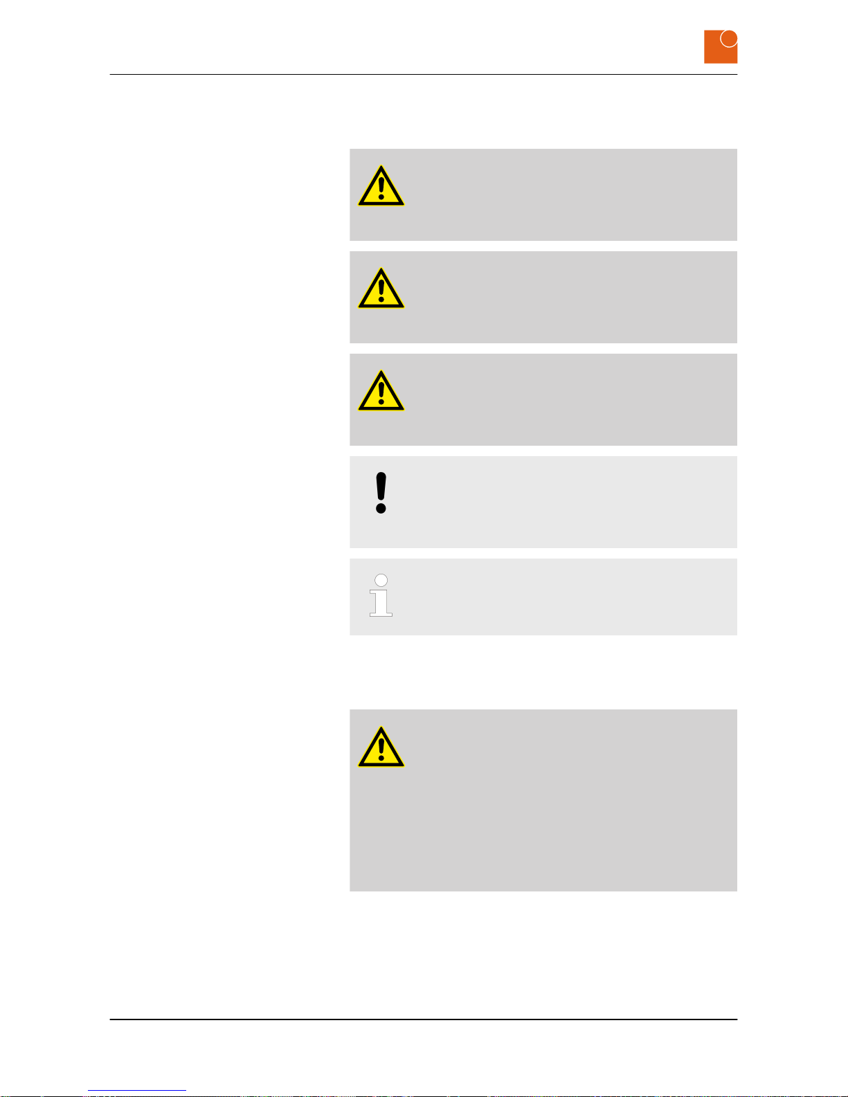
DANGER!
This signals an unusually hazardous situation. Failure to
comply with these instructions will result in serious irreversible injuries or death.
WARNING!
This signals an unusually hazardous situation. Failure to
comply with these instructions may result in serious irreversible or fatal injuries.
CAUTION!
This signals a hazardous situation. Failure to comply with
these instructions may result in minor or moderate injuries.
NOTICE!
This signals a hazard for material property. Failure to
comply with these instructions may cause material
damage.
This signals useful hints within a series of work processes.
2.3 Important safety notes
DANGER!
Electric shock hazard if the device is connected to the
mains supply incorrectly.
Connecting the device incorrectly to the mains supply
may expose people to injuries from electric shocks.
– Before connecting up the device always disconnect
the line from the power supply.
– Before connecting up always check that the lines are
at zero voltage.
Safety
Important safety notes
PILOT 219 PC - Industrial PC
8

WARNING!
Risk of injury from electric shock!
Assembling and connecting plug connectors while
voltage is connected may lead to life-threatening injuries.
– All work on the device must be carried out when the
supply line is free of voltage.
– Never plug in or unplug the power supply plug when
live with voltage.
– The supply cable must not be supplied with voltage
until assembly has completely finished.
WARNING!
Danger of injury from hot surfaces.
Power transmission and regulatory components become
hot in operation and may lead to injuries.
– Allow these components to cool down before you
begin dismounting the device.
WARNING!
Danger of injury due to excessive load.
Working on heavy equipment may lead to serious injuries.
– Always have two people when working with heavy
equipment.
NOTICE!
Damage caused by improper bending of the cables!
Strong bending of the cables may cause material damage.
– Only bend the cables with a minimum bending radius
of 9.1 cm.
In order to ensure proper use of the keyboard, the USB port of
the keyboards should not exceed a maximum cable length of
3 meters. Other lengths on request.
Safety
Important safety notes
PILOT 219 PC - Industrial PC
9

Safety
Important safety notes
PILOT 219 PC - Industrial PC
10
3 Product description
3.1 Overview
HMI systems from Systec & Solutions GmbH are user interfaces for managing and observing ongoing production processes. All devices are
highly available units designed in stainless steel, particularly suited to
harsh conditions in the process industry and, in addition, they guarantee IP65 protection.
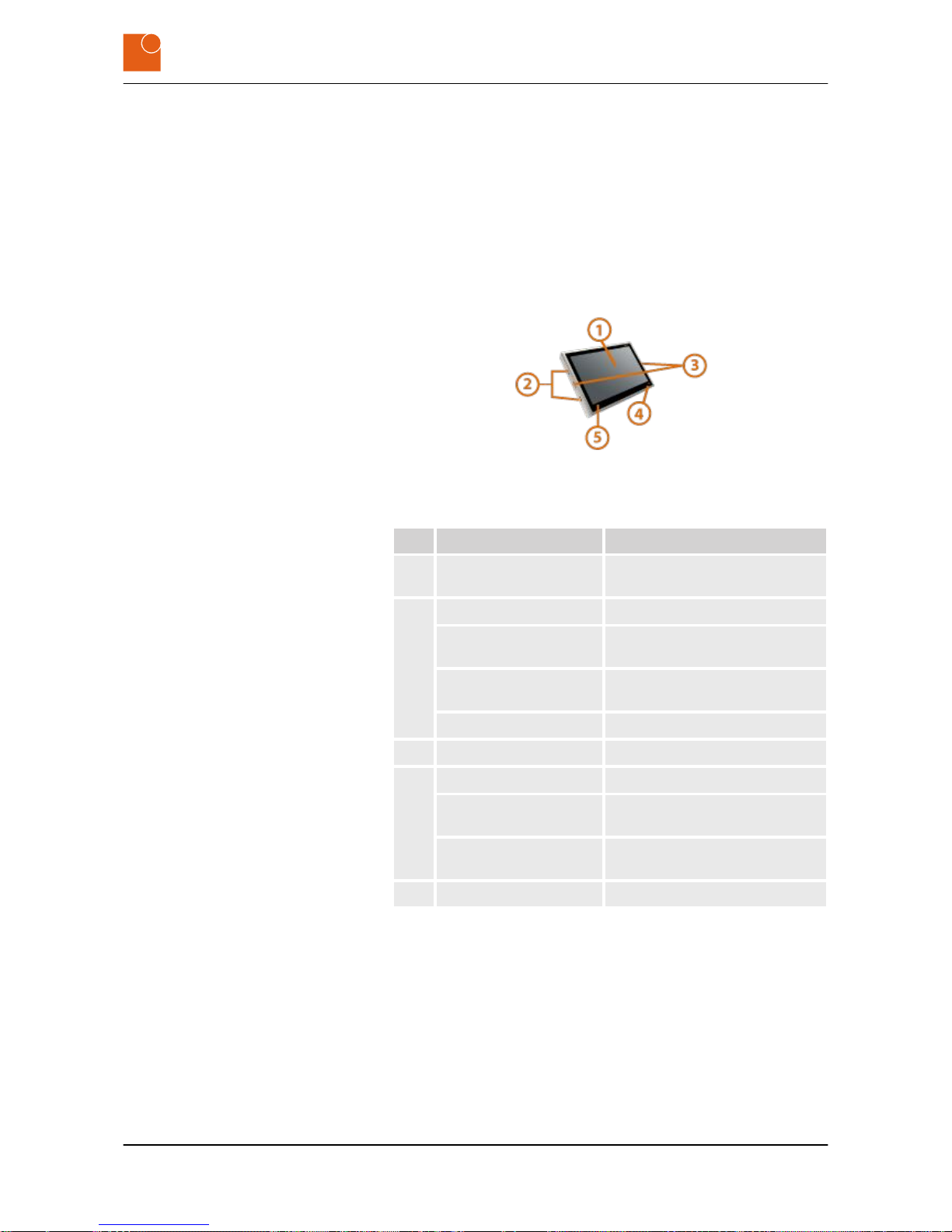
Fig. 1: PILOT 219 PC
No. Designation Description
1 Display / Touchscreen Used to display information and
control the device.
2 On/Off Switches the device on and off.
USB connection
(optional)
Used to connect a USB stick.
Bluetooth (optional) Used to connect peripheral
devices, e.g. scanner.
RFID (optional) Used for user identification.
3 Speaker Used for audio output.
4 Capacitive On/Off button Switches the device on and off.
Function keys Custom keyboard shortcuts (Ctrl +
Alt + Del, for example).
Hard disk LED (optional) Flashes when accessing data on
the internal HDD disk.
5 RFID (optional) Used for user identification.
HMI system PILOT 219 PC
Device
Product description
Overview
PILOT 219 PC - Industrial PC
11

Fig. 2: Rear view of PC
The button on the back of the monitor is used to switch the PC ON and
OFF.
Fig. 3: PILOT 219 PC
Nr Designation Description
1 Camera Used to record images.
2 Microphone Used to record sound.
Multimedia kit (optional)
Product description
Overview
PILOT 219 PC - Industrial PC
12

3.2 Type plate
The product designation and identification will be found on the type
plate. This is always located on the rear of the device and contains the
following information:
Fig. 4: Position of type plate
Fig. 5: Type plate
No. Description
1 Product name
2 Serial number
3 Power supply and consumption, charge current
and battery capacity (only for devices with an inte-
grated battery)
4 CE/FCC mark
5 Manufacturer’s logo
6 QR code (S/N + product name)
7 Manufacturer’s address
Product description
Type plate
PILOT 219 PC - Industrial PC
13

3.3 Technical data for the device
System
Model PILOT 219
Variant Industrial PC
Housing material Housing of stainless steel 1.4301, rear wall of stainless steel 1.4301 (CPU
i3, i5, i7 aluminum AlMg3)
Surface sanded
IP protection factor IP65
PC
CPU
Intel ® Celeron™ N2930 1.86 GHz/Burst 2.16 GHz, quad core
Intel ® Core™ i3-4010U 1.7 GHz
Intel ® Core™ i5-4300U 1.9 GHz/Turbo 2.9 GHz
Intel ® Core™ i7-4650U 1.7 GHz/3.3 GHz
RAM 4 GB DDR3, max. 16 GB DDR3 (Celeron 8 GB)
Storage capacity 120 GB mSATA SSD; HDD und SLC-SSD (optional)
Operating system
Windows® 7
Windows® 8.1
Windows® 10 32 Bit/64 Bit
Android (optional)
IGEL Thin-Client (For further information, see the manufacturer’s website
www.igel.com.)
Display
Type of display 19" IPS LCD display with LED backlight
Display area 376.32 x 301.06 mm
Native (maximum) resolution 1280 x 1024 (SXGA)
Page ratio 4:3
Colors 16.7 million
Contrast 2000:1
Touchscreen (optional) mouse compatible, analog resistive or PCT (projected capacitive) multi-
touch, optical bonding with laminated polyester layer
Product description
Technical data for the device
PILOT 219 PC - Industrial PC
14

Interfaces
Standard interfaces 2x RS232, 4x USB,1x Ethernet, optional: 3x RS232, 2-4 USB 3.0, 2x Gigabit
Ethernet (Intel® Celeron® 1x USB 3.0, 5x USB 2.0, 1-2x Ethernet), additional
interfaces (optional)
IGEL Thin-Client (optional) 4 x USB-A
Power supply / consumption
(depending on the device variant)
Extra-low voltage power supply
12 ‒ 24 V DC, 10 ‒ 5 A
Protection of supply lead (Extra-low
voltage DC)
max. 10 A, the supply lead should be specified.
Low voltage power supply
100 ‒ 240 V AC, 50 ‒ 60 Hz, 2.0 ‒ 0.9 A
Protection of supply lead (Low voltage
AC)
max. 16 A, the supply lead should be specified.
Mean power consumption in operating mode
55 - 70 W (depending on configuration)
Environmental conditions
Storage
-20 °C ‒ +60 °C
Operation
0 °C ‒ +40 °C (55 °C optional)
Humidity
10 % ‒ 90 %; non condensing
Dimensions (in mm without keyboard hinge)
Width 470
Height 400
Depth 55
Weight
Net weight ca. 10 kg
Product description
Technical data for the device
PILOT 219 PC - Industrial PC
15

3.4 Dimensions
Fig. 6: Dimensions of front of device
Fig. 7: Dimensions of back of device
Product description
Dimensions
PILOT 219 PC - Industrial PC
16

Fig. 8: Dimensions in side view
3.5 External connections
3.5.1 Overview of external connections
The following illustration shows the connectors that are located on the
back of the PILOT 219 PC.
Fig. 9: Overview of the interfaces on the back (depending on the configuration)
Product description
External connections > Overview of external connections
PILOT 219 PC - Industrial PC
17

3.5.2 Description of the external connections
Your device will not incorporate all of the following connectors (see
Ä
Chapter 3.3 “Technical data for the device” on page 14).
= 9-pole Sub-D socket for connecting serial devices
Fig. 10: Serial connection (RS‑232)
= 24-pole DVI socket for connecting to the basic computer
Fig. 11: DVI socket with pinout
= 19-pole HDMI socket for connecting to the basic computer
Fig. 12: HDMI socket with pinout
= 15-pole HD-D "VGA" socket for connecting basic computer
Fig. 13: VGA socket with pinout
Serial connection (RS‑232)
DVI port
HDMI port
VGA port
Product description
External connections > Description of the external connections
PILOT 219 PC - Industrial PC
18

= 20-pole DisplayPort socket for connecting basic computer
Fig. 14: DisplayPort socket with pinout
= 4-pole USB socket (type A) for connecting components:
n VoIP hardware components and/or
n touchscreen and/or
n keyboard
Fig. 15: USB socket with pinout
= 9-pole USB 3.0 socket for connecting components:
n VoIP hardware components and/or
n touchscreen and/or
n keyboard
Fig. 16: USB 3.0 socket with pinout
= 8-pole Ethernet socket for connecting to a network
Fig. 17: Ethernet socket with pinout
DisplayPort
USB connection
USB 3.0 connection
Ethernet (RJ45)
Product description
External connections > Description of the external connections
PILOT 219 PC - Industrial PC
19

3.5.2.1 Power supply
NOTICE!
Risk of material damage if the device is connected to
an incorrect power supply.
Connecting the device to an incorrect power supply may
cause material damage.
– Check the power rating of your device.
Power is supplied via a 2-pole Phoenix socket of type DFK-PC /2GF-7,62. The corresponding plug carries the designation Phoenix Contact PC 4/ 2-ST-7,62.
Fig. 18: 2-pole Phoenix Contact socket for the power supply
Pin Designation Significance
1
-
Ground (GND) 0V
2 + Power supply +
Power is supplied via a 3-pole Phoenix socket of type DFK-PC /3GF-7,62. The corresponding plug carries the designation Phoenix Contact PC 4/ 3-ST-7,62.
Fig. 19: 3-pole Phoenix Contact socket for the power supply
Pin Designation Significance
1 PE Surge protectors
2 L Phase
3 N Neutral conductor
Power supply in the extra low voltage
range (12‑24V DC)
Power supply in the low-voltage
range (100 – 240 V AC, 50 – 60 Hz)
Product description
External connections > Description of the external connections
PILOT 219 PC - Industrial PC
20

3.6 Conformity
The devices of Systec & Solutions GmbH meet the requirements of the
EC Directives 2014/30/EU (formerly 2004/108/EG) and 2014/35/EU (formerly 2006/95/EG).
PILOT 215-217-218-219-221
Industrial PC/Monitor
2014/30/EU (formerly 2004/108/EC) and 2014/35/EU (formerly 2006/95/
EC)
n PURPOSE
For the above product, in the version with a 12 – 24 V DC power
supply, we hereby confirm that it complies with the essential protection requirements of the EMC Directive 2014/30/EU (formerly
2004/108/EC) (electromagnetic compatibility).
The above product, in the version with a 100 – 240 V AC power
supply, also complies with the requirements of the EC Low Voltage
Directive 2014/35/EU (formerly 2006/95/EC).
n SCOPE
The product listed above fulfills the requirements of the EMC Directive 2014/30/EU (formerly 2004/108/EC) on the basis of the following standards:
– EN 61000-6-2:2006
– EN 61000-6-4:2011
The product listed above fulfills the requirements of the Directive
2006/95/EC on the basis of the following standard:
– EN 60950-1:2007
n CERTIFICATE
Compliance with protection requirements was established with the
housing closed on all sides.
Systec & Solutions GmbH
Emmy-Noether-Straße 17
D–76131 Karlsruhe
Germany
Phone +49 721 6634 400
Fax +49 721 6634 444
talk@systec-solutions.com
www.systec-solutions.com
Karlsruhe, January 1, 2017
Philipp Linder
Managing Director (CTO)
Declaration of Conformity
Product description
Conformity
PILOT 219 PC - Industrial PC
21

Product description
Conformity
PILOT 219 PC - Industrial PC
22

4 Starting up
4.1 Unpacking the device
1. Check the packaging for damage.
2. Remove the packaging carefully to avoid damaging the contents.
3. Check the device for damage.
If you find the packaging or the device to be damaged,
immediately inform the haulage company and the
supplier. Document the damage in some appropriate
way (e.g. incoming goods report, photos).
4. Check the delivered goods against your order and the delivery
papers to make sure everything is present and correct.
5. Retain the original packaging.
Retain the original packaging so that it can be reused
for
– storage,
– transport and
– return for disposal
as and when necessary.
If you fail to do this it will no longer be possible to guar-
antee protection from damage or other harmful influences.
4.2 Setting up the device
The device is approved for operation in enclosed premises.
1. Prior to initial commissioning:
n If necessary, disinfect the device (spray or wipe with disinfec-
tant) (refer to the device’s chemical resistance
data
Ä
on page 30).
n Slowly acclimatize the device to room temperature.
2. In the event of condensation: Do not switch the device on until it
is absolutely dry.
3. To avoid overheating during subsequent operation:
n Do not expose the device to solar radiation or other sources
of heat
n Make sure the ambient temperature does not exceed the
specified maximum value (see
Ä
Chapter 3.3 “Technical data
for the device” on page 14).
When installing the equipment also observe Ä Chapter 3.4 “Dimensions” on page 16.
Starting up
Setting up the device
PILOT 219 PC - Industrial PC
23

4.3 Mounting the device
1. Make sure the device is installed in a location with adequate air
circulation to ensure its operating temperature remains within
the permitted limits.
The device is cooled by means of an internal fan. This
device has no ventilation holes because waste heat is
conducted away via the metal housing.
2.
WARNING!
Danger of injury due to excessive load.
Working on heavy equipment may lead to serious
injuries.
– Always have two people when working with
heavy equipment.
Hold the PILOT 219 PC firmly so that it is level with the equipment rack adapter.
Starting up
Mounting the device
PILOT 219 PC - Industrial PC
24

3.
WARNING!
Risk of injury from electric shock!
Assembling and connecting plug connectors while
voltage is connected may lead to life-threatening
injuries.
– All work on the device must be carried out
when the supply line is free of voltage.
– Never plug in or unplug the power supply plug
when live with voltage.
– The supply cable must not be supplied with
voltage until assembly has completely finished.
There must be a cut-off device provided in the electric
supply cable of the device.
– If being permanently connected to the building
installation, an easily accessible cut-off device
must be in place.
– In the case of plug-in connection, the power socket
must be installed near the device and must be
easily accessible.
Connect the electrical supply cable with the device.
Please consider also
– the technical data for the external connec-
torsÄ Chapter 3.5 “External connections”
on page 17
– and the requirement for the electrical supply
lead
Ä
Chapter 3.3 “Technical data for the device”
on page 14.
Starting up
Mounting the device
PILOT 219 PC - Industrial PC
25

Fig. 20: Interface plate on the rear of the PILOT 219 PC (depending on the
configuration)
4. Connect up all the cables between the interface plate and the
equipment rack adapter.
5. Tighten the screws on the mains plug.
6. Fasten the PILOT 219 PC to the equipment rack adapter using the
four M5 x 16 screws.
You will find a view of the backplane in section Ä Chapter 3.4
“Dimensions” on page 16.
Fig. 21: Screw connections on the equipment rack adapter
ð
The PILOT 219 PC is now mounted.
Starting up
Mounting the device
PILOT 219 PC - Industrial PC
26
5 Operation
5.1 Switching the device on
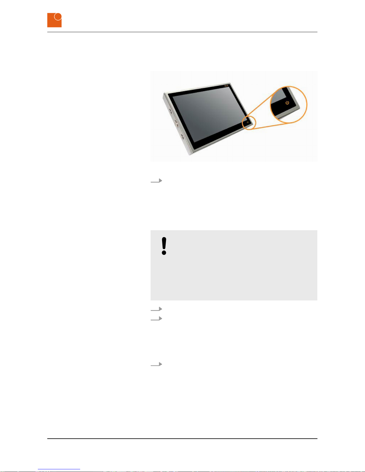
Fig. 22: ON/OFF button for switching on and off
Press the ON/OFF on the right-hand front side of the PILOT 219
PC.
ð
The system goes into operation.
5.2 Switching the device off
NOTICE!
Loss of data due to failure to save it.
Failure to save your data or failure to close down the
industrial PC in an orderly fashion may cause you to lose
data and may also damage the components.
– Save your data regularly.
– Always close down the industrial PC in an orderly
fashion.
1. Close the system down in an orderly fashion.
2. Press the ON/OFF on the right-hand front side of the PILOT 219
PC.
ð
The system is switched off.
The system cannot be closed down in an orderly fashion.
Hold the ON/OFF button pressed for about five seconds.
ð
The system is switched off.
Operation
Switching the device off
PILOT 219 PC - Industrial PC
27

5.3 Operating the touchscreen
With PCT (projected capacitive) multi-touch there is no need
to install a driver.
Install the installation files on the supplied USB stick.
If the stick is not available: Send an e‑mail to
support@systec-hardware.com.
When Projected Capacitive Touch:
1. Launch Tablet PC Settings in Windows’ Control Panel.
ð
A new window opens up.
2. Choose the Calibration option.
3. Further instructions follow.
ð
The touchscreen is correctly calibrated.
When resistive Touch:
1. Install the installation files on the supplied USB stick.
2. Calibrate touchscreen within the installed software.
ð
The touchscreen is correctly calibrated.
If the stick is not available: Send an e‑mail to
support@systec-hardware.com.
5.4 Cleaning the device
To prevent malfunctions or incorrect data entry due to inadvertent
operations: Switch the device off before cleaning it (see Ä Chapter 5.2
“Switching the device off” on page 27).
Installing the driver
Windows 7 and higher
Calibrating the touchscreen
Windows 7
Operation
Cleaning the device
PILOT 219 PC - Industrial PC
28

NOTICE!
Damage caused by cleaning.
Cleaning the device may give rise to material damage.
– Firmly close all screw connections.
– Do not use high-pressure or steam cleaning equip-
ment.
– Do not use any abrasives or hard materials.
– Clean the display without applying any excessive pres-
sure.
1. Regularly clean the surface of the device using a soft, moist, lint-
free cloth.
2. For more significant soiling: Use isopropanol as cleaning agent.
Operation
Cleaning the device
PILOT 219 PC - Industrial PC
29

Note the information in the following chemical resistance data:
HMI system with films for touchscreen, passepartout and cover sheets,
seals
Chemical resistance
n RESISTANCE
to solvents and environmental influences.
The film usually used is based on a polyester film with biaxial orienta-
tion, which therefore has a better resistance to solvents. It can withstand pencil hardness 3HB.
The whole HMI system and all used films are able to withstand over 24
hours exposure to the following chemicals at 50°C without visible
damage. Concentration 100% (except where otherwise stated):
Acetaldehyde Dioctyl phthalate Caustic soda <10%
Acetone Dioxane Paraffin oil
Acetonitrile Dowandol DRM/PM Perchlorethylene
Aliphatic hydrocar-
bons
Ferrous chloride
(FeCl2)
Phosphoric acid
<10%
Alkaline carbonate Ferric chloride(FeCl2) Castor oil
10% formic acid Acetic acid <10% Nitric acid <10%
Ammonia <10% Ethanol Hydrochloric acid
<10%
Amyl acetate Ethyl Salt water
Ethanol Ethyl acetate Oxygen
Ether Varnish Sulfuric acid <10%
Ethyl acetate Chlorofluorocarbons Silicone oil
Gasoline Formaldehyde 37% -
42%
Turpentine substitute
Benzene Glycol Toluol
Bichromate Glycerine Triacetin
Ferrocyanide salts Heating oil III-trichloroethane
Drilling emulsion Isopropanol Trichloroethylene
Brake fluid Potash soap Trichloroacetic acid
<10%
Butyl cellosolve Potassium hydroxide
<30%
Tricresyl phosphate
Sodachlorine <20% Kerosene Thinner (white spirit)
Cyclohexanol Cresol phenol soaps
in solution
Soaps, dishwasher
and detergent solu-
tions
Decon Methanol Water <100°C
Operation
Cleaning the device
PILOT 219 PC - Industrial PC
30

Diacetone alcohol Methyl ethyl ketone Hydrogen peroxide
<25%
Diethylformamide Molecular chlorine Fabric softener
Dibutyl phthalate N-butyl acetate Xylene
Diesel oil Sodium bisulfate
Diethylether Sodium carbonate
The film is not resistant to the following chemicals:
Concentrated mineral
acids
Concentrated alkaline
solutions
High pressure steam
above 100°C
A number of other substances may give rise to changes in the surface
structure. This should be examined and evaluated in each case.
Resistant to 24-hours' exposure to household chemicals at 50°C
with no visible damage:
Ariel Gumption Top Job
Ajax Jet Dry Grape juice
Domestos Coffee Vim
Downey Lenor Vortex
Fantastic Milk Wisk
Formula 409 PersiI Windex
Slight discoloration was detectable for the following materials:
Mustard Tomato ketchup
Tomato juice Lemon juice
n SCOPE
This customer information applies to the following devices manufactured by Systec & Solutions GmbH:
– CONTROL 217 | 218 | 219 | 221 | 224 | 232
– PILOT 215 | 217 | 218 | 219 | 221
– WAVE 219 | 221 | 224 | 232 | 255
n PURPOSE
This document serves to inform customers about product attributes. The information is provided by the manufacturer or supplier.
The information and recommendations it contains are made to the
best of our knowledge and belief. Users should carry out their own
investigations to establish usage and application recommendations relating to products’ suitability for their particular purpose.
Systec & Solutions GmbH
Emmy-Noether-Straße 17 | 76131 Karlsruhe | Germany
Phone +49 721 6634 400 | Fax +49 721 6634 444
talk@systec-solutions.com | www.systec-solutions.com
Operation
Cleaning the device
PILOT 219 PC - Industrial PC
31

5.5 Using the optional USB connection
Unscrew and remove the dummy plug on the left-hand side of
the PILOT 219 PC.
ð
The optional USB connection is now accessible.
When closing the USB connection, make sure it is
screwed tight, otherwise the IP65 protection level can
no longer be guaranteed.
Firmly screw the dummy plug into place on the left-hand side of
the PILOT 219 PC.
ð
The optional USB connection is firmly screwed shut.
5.6 Setting up the WLAN (optional)
The WLAN antenna together with the WLAN USB stick are
located in the equipment rack adapter.
The WLAN USB stick may be connected only directly to a USB
interface with no interposed USB hub.
Install the WLAN driver from the supplied USB stick.
ð
The WLAN is set up.
5.7 Hard disk LED (optional)
The hard disk LED flashes when the internal HDD hard disk is
accessed.
This is, however, possible only for HDD disks.
Opening dummy plugs
Closing dummy plugs
Operation
Hard disk LED (optional)
PILOT 219 PC - Industrial PC
32

6 Repairs
If you encounter a product fault while using the device:
– immediately switch it off (see Ä Chapter 5.2 “Switching
the device off” on page 27).
The device is defective.
1. Send an e-mail to support@systec-solutions.com or
2. Fill out a support form at
https://www.systec-solutions.com/en/support/.
Repairs
PILOT 219 PC - Industrial PC
33

Repairs
PILOT 219 PC - Industrial PC
34

7 Storage
7.1 Unmounting the device
WARNING!
Risk of injury from electric shock!
Assembling and connecting plug connectors while
voltage is connected may lead to life-threatening injuries.
– All work on the device must be carried out when the
supply line is free of voltage.
– Never plug in or unplug the power supply plug when
live with voltage.
– The supply cable must not be supplied with voltage
until assembly has completely finished.
WARNING!
Danger of injury due to excessive load.
Working on heavy equipment may lead to serious injuries.
– Always have two people when working with heavy
equipment.
WARNING!
Danger of injury from hot surfaces.
Power transmission and regulatory components become
hot in operation and may lead to injuries.
– Allow these components to cool down before you
begin dismounting the device.
NOTICE!
Danger of material damage from live equipment.
Working on live equipment may give rise to material
damage.
– Before you carry out any work on a device: Disconnect
it from the power supply.
You will need the following tools:
n Allan key (4) for M5 x 16
n Philips screwdriver for the plug
n Slot screwdriver
Storage
Unmounting the device
PILOT 219 PC - Industrial PC
35

1.
Clean the device (see Ä Chapter 5.4 “Cleaning the device”
on page 28).
Fig. 23: Screw connections on the equipment rack adapter
2. Release the screw connections on the equipment rack adapter.
3. Lift the device off the equipment rack adapter and hold it firmly.
ð
You can now see the interface plate on the rear of the device.
Fig. 24: Interface plate on the rear of the PILOT 219 PC (depending on the
configuration)
4. Release the screws on the mains plug.
5. Disconnect the device from the power supply.
6. Disconnect all the cables from the interface plate.
ð
The device is now unmounted.
Storage
Unmounting the device
PILOT 219 PC - Industrial PC
36

7.2 Storing the device
NOTICE!
Material damage caused by incorrect storage.
Incorrect storage can damage the device.
– Pay attention to the handling symbols on the pack-
aging.
– Comply with the stated storage conditions (see
Ä
Chapter 7.2 “Storing the device” on page 37).
When storing the device, comply with the following requirements:
n Use the original packaging.
n Do not apply any localized pressure to the display.
n Do not store in the open air.
n Always store in a dry, non-dusty place.
n Always shield the equipment from solar radiation.
n Avoid mechanical vibration and shocks.
n Avoid cold weather and extreme temperature fluctuations.
n Pay attention to the information in the “Technical data” section.
Ä
Chapter 3.3 “Technical data for the device” on page 14
Storage conditions
Storage
Storing the device
PILOT 219 PC - Industrial PC
37

Storage
Storing the device
PILOT 219 PC - Industrial PC
38

8 Packaging and transport
8.1 Packaging the device
The packaging protects the contents from damage or other deleterious
effects that could adversely affect their quality.
Retain the original packaging so that it can be reused for
– storage,
– transport and
– return for disposal
as and when necessary.
If you fail to do this it will no longer be possible to guarantee
protection from damage or other harmful influences.
8.2 Transporting the device
NOTICE!
Material damage caused by inappropriate transport.
Inappropriate transport may damage the device.
– Pay attention to the handling symbols on the trans-
port packaging.
– Comply with the stated transport requirements (see
Ä
“Transport requirements” on page 39).
When transporting the device you should comply with the following
requirements:
n Always shield the equipment from solar radiation.
n Avoid mechanical vibration and shocks.
n Avoid extreme temperature fluctuations.
n Pay attention to the information in the “Technical data” section.
When the consignment is delivered, immediately check it for
possible transport damage and deal appropriately with any
detected transport damage or non-obvious defects.
Transport requirements
Packaging and transport
Transporting the device
PILOT 219 PC - Industrial PC
39

Packaging and transport
Transporting the device
PILOT 219 PC - Industrial PC
40

9 Disposal
This device is subject to the WEEE Directive and the corresponding
national statute (ElektroG).
n WEEE registration number: 79305117
Systec & Solutions GmbH undertakes to take back and dispose properly
of all devices. Under our General Terms and Conditions and in fulfillment of the conditions of the sales agreement, the customer undertakes to return all equipment to Systec-Services GmbH for proper disposal.
Do not dispose of the equipment via your local municipal collection centers. Under the WEEE Directive these may be used
only for privately used equipment.
Disposal
PILOT 219 PC - Industrial PC
41

Disposal
PILOT 219 PC - Industrial PC
42

10 Site information
Systec & Solutions GmbH
Emmy-Noether-Straße 17
D–76131 Karlsruhe
Germany
Phone: +49 721 6634 400
Fax: +49 721 6634 444
E-mail: talk@systec-solutions.com
Internet: www.systec-solutions.com
Support: support@systec-solutions.com
Support form: https://www.systec-solutions.com/en/support/
n Andreas König
n Philipp M. Linder
Court of registration: Mannheim District Court
Registration number: HRB 717236
VAT ID no. as per §27a Value Added Tax Act:
n DE 815434969
© Systec & Solutions GmbH / All rights reserved
Technical modifications reserved
All trademarks and registered trademarks mentioned are the property
of their respective owners
Authorized representatives and directors
Site information
PILOT 219 PC - Industrial PC
43
 Loading...