


NDS/5000 and NDS/6000
Hardware
Manual
SYSTECH
C O R P O R A T I O N
Document number 80-001060-5
Revision B


NDS/5000 and NDS/6000
Hardware
Manual

Document part number 80-001060-5
Revision History
Date Revision Description
7/15/03
A
Initial release
1/31/08
B
Added 8 and 16 port
versions
Created 2003, and Protected Under the U.S. Copyright Act of 1976.
Copyright © 2003, 2008 SYSTECH Corporation
All Rights Reserved
This document is subject to change without notice.

Agency Notifications
This device complies with Part 15 of the FCC Rules. Operation is subject to the following two
conditions: (1) this device may not cause harmful interference, and (2) this device must accept
any interference received, including interference that may cause undesired operation.


Table of Contents
CHAPTER 1: OVERVIEW...........................................................................................3
NDS Features ...................................................................................................................4
Description of NDS Models ............................................................................................5
Using the NDS ................................................................................................................. 6
CHAPTER 2: INSTALLING THE HARDWARE ..........................................................7
Overview..........................................................................................................................7
Planning the installation.................................................................................................7
NDS Panel Connectors ...................................................................................................8
Connecting Devices to the NDS...................................................................................10
NDS/5000 RS-232 Operation.....................................................................................10
NDS/6000 RS-232 Operation.....................................................................................14
RS-422/485 Operation................................................................................................18
Ethernet LAN..............................................................................................................20
Starting the NDS............................................................................................................21
CHAPTER 3: USING RS-422 AND RS-485 DEVICES.............................................23
Connecting RS-422/485 Devices..................................................................................23
RS-422/485 Point-to-point Configuration ....................................................................23
RS-422/485 Bus Configurations .................................................................................24
Two-Wire System................................................................................................................... 24
Four-Wire Systems.................................................................................................................26
Using the NDS in RS-422 or RS-485 Mode ..................................................................26
CHAPTER 4: TROUBLESHOOTING........................................................................ 27
Status LED.....................................................................................................................27
Serial Port LEDs............................................................................................................28
Ethernet LEDs ...............................................................................................................28
APPENDIX: SPECIFICATIONS................................................................................29
NDS Hardware Specifications......................................................................................29
Environmental Specifications......................................................................................29
Product Dimensions ..................................................................................................... 29
Model Numbers.............................................................................................................30
Ethernet cabling specifications ................................................................................... 30

Chapter 1: Overview
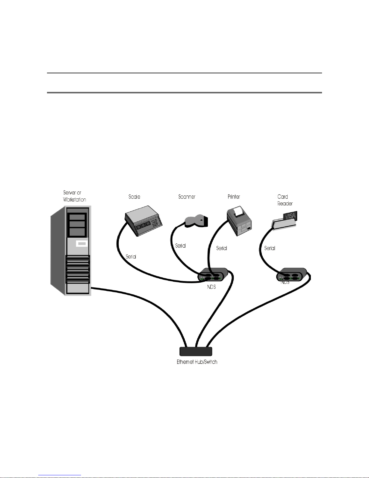
The NDS port server provides communication between peripheral devices and computers
connected to a network. When the NDS is connected to your LAN and to one or more
peripherals, it manages network traffic, routing it to the correct device. For example, the
network diagram below shows how the NDS might be used to allow one or more PCs to
share expensive peripherals or to access peripherals that are located elsewhere on the local
or remote network.
Overview 3

NDS Features
The NDS offers the following features and benefits:
• Easy web-based set up and configuration
• Open systems communications for multi-site data networks
• Can be used in a variety of data communications applications
• NDS-6000: 2, 4 or 8 DB-9 (with screw-down connectors)
• NDS-5000: 2, 4, 8 or 16 RJ-45 serial ports
• RS-232 and RS-422/RS-485 software configurable on all ports
• Standard single RJ-45, 10/100 Base-TX Ethernet port
• Optional four-port RJ-45, 10/100 Base-TX Ethernet switch (standard on 8 and 16 port
units)
• Optional 100 Base-FX Fiber Ethernet port on one of the switch ports (not available on 8
and 16 port units)
• High-speed serial connections (up to 230.4K baud)
• IP packet routing
• Operating system independent
• Complete remote diagnostics
• LEDs for each port, signaling port status and error conditions
• Industry standard interoperability
• Supports NativeCOM, allowing serial ports to appear as local Windows COM ports
• Supports generic TCP/IP access to serial ports without requiring special protocols or
processing
• Standard support for LPR/LPD network printing under Windows and UNIX
• Telnet and reverse-telnet support for a variety of UNIX operating systems
NDS Features4

Description of NDS Models
The NDS is available in the 5000 and 6000 series of models. These products are functionally
equivalent except for the serial port connectors. The NDS/5000 series of products have
RJ-45 serial connectors. The NDS/6000 series of products have DB-9 serial connectors.
Standard units have a plastic enclosure. Rackmount units have a metal enclosure.
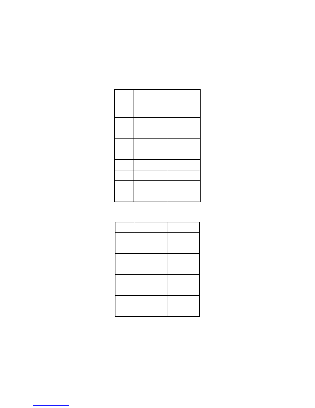
The model number describes the number of ports and types of Ethernet connections.
Model Number of
Serial Ports
NDS/5102 2 RJ-45 One 10/100TX
NDS/5202 2 RJ-45 Four 10/100TX
NDS/5302 2 RJ-45 Three 10/100TX
NDS/6102 2 DB-9 One 10/100TX
NDS/6202 2 DB-9 Four 10/100TX
NDS/6302 2 DB-9 Three 10/100TX
NDS/5104 4 RJ-45 One 10/100TX
NDS/5204 4 RJ-45 Four 10/100TX
NDS/5304 4 RJ-45 Three 10/100TX
NDS/6104 4 DB-9 One 10/100TX
NDS/6204 4 DB-9 Four 10/100TX
Type of Serial
Connector
Ethernet
Connectors
One 100FX (Fiber)
One 100FX (Fiber)
One 100FX (Fiber)
NDS/6304 4 DB-9 Three 10/100TX
NDS/5008 8 RJ-45 Four 10/100TX
NDS/5008-RM
Rackmount
NDS/6008 8 DB-9 Four 10/100TX
NDS/6008-RM
Rackmount
NDS/5016 16 RJ-45 Four 10/100TX
NDS/5016-RM
Rackmount
One 100FX (Fiber)
8 RJ-45 Four 10/100TX
8 DB-9 Four 10/100TX
16 RJ-45 Four 10/100TX
Overview 5

Using the NDS
Using the NDS requires three steps:
1. Hardware installation
2. Configuration
3. Operation
Hardware installation is documented in this manual.
Refer to the
NDS Administrator's Guide for configuration and operation.
Using the NDS6

Chapter 2: Installing the Hardware
This chapter describes installing the NDS hardware, including:
• Planning the installation
• Checking cables and connectors
• Sample configurations
Overview
Installing the NDS hardware includes the following steps:
1. Plan the installation
2. Connect the NDS port server to your network
The most common connection method is through the 10/100 Base-TX RJ-45 connector
(which is labeled LAN) to your Ethernet LAN, using a standard straight-through
Ethernet cable to a hub/switch.
3. Connect your peripheral device(s) to the NDS port server
Attach each peripheral device (e.g., cash register, card reader, modem) to a serial port
(one of the DB-9 or RJ-45 connectors).
4. Plug the AC power supply adapter into the NDS
Planning the installation
Before installing the NDS remote communications server, consider the following:
• How will you configure your network—what types of devices will you connect and
where will they be located? Identify the distances at which each device will be located
from the NDS server.
• Verify that the locations selected for devices do not exceed cable specifications.
• Is there an acceptable source of AC power available near each device’s proposed
location?
Installing the Hardware 7

NDS Panel Connectors
The following figures show the connectors and LED locations for the NDS models. There
are:
• 2-8 DB-9 or 2-16 RJ-45 serial ports
• 1-4 RJ-45 Ethernet ports and
• an optional Fiber (100FX) port (2-4 port models only)
STATUS RESET
STATUS RESET
Figure 2-1: NDS 2-4 Port Front Panel Connectors
1
2
1
2
1
2
1
3
2
4
3
4
3
4
5
6
5
6
7
8
7
8
3
4
ABC
STATUS
D
1
3
2
4
Figure 2-2: NDS 8-16 Port Front Panel Connectors
NDS Panel Connectors8
567891011
13
12
15
14
16
ABC
D

10/100TX
LAN
10/100TXA10/100TXB10/100TXC10/100TX
D
+5V
ONLY
+5V
ONLY
ABCD
10/100TX
10/100TXB10/100TXC100FX
A
D
+5V
ONLY
ABCD
Figure 2-3: NDS 2-4 Port Rear Panel Connectors
10/100 TXA10/100 TXB10/100 TXC10/100 TX
DEBUG
D
UNLOCK/LOCK
POWER
Figure 2-4: NDS 8-16 Port Rear Panel Connectors
The Unit Status LED indicates the overall status of the device. The Port Status LEDs indicate
the status of each serial port. The LAN LED(s) indicate the status of the Ethernet
connection(s). For information on interpreting the LED color and pattern displays, see
Troubleshooting.
The reset button can be used to reboot the unit or to restore the factory default configuration
on the unit. Depressing and releasing the button will reboot the unit.
Depressing and holding the "Reset" button in for about 5 seconds will restore the default
(factory) configuration to the unit and then reboot the unit.
Installing the Hardware 9
Connecting Devices to the NDS
The NDS serial ports may each be independently configured via software, to operate in RS232, RS-422 or RS-485 mode. The following sections describe the pinouts and cabling
options associated with these different modes.
NDS/5000 RS-232 Operation
The NDS/5000 server family uses a symmetrical EIA-232/RS-232 data terminal equipment
(DTE) pinout on the RJ-45 serial ports. Table 2-1 lists the pinouts of the RJ-45 ports used for
EIA-232 serial communications.
RJ-45
Pin
Number
1 DCD I Signals module that remote device is
2 RTS O Flow control, to enable remote device to
3 SG Signal return (NOT chassis ground)
RS-232
Name Direction Signal Function
attached and powered on
send data
4 TXD O Serial data out, from NDS to remote device
5 RXD I Serial data in, from remote device to NDS
6 SG Signal return (NOT chassis ground)
7 CTS I Flow control, to enable NDS to send data on
TXD
8 DTR O Signals remote device that NDS is attached
and powered on
Table 2-1: EIA-232 RJ-45 Pinouts
To connect your EIA-232 device to the serial port of an NDS/5000, you need to determine
whether the device connector wiring follows the standard for data terminal equipment
(DTE) or for data communication equipment (DCE). In general, modems are wired as DCE
devices and all other devices are wired as DTE; however, some equipment manufacturers
may deviate from the standard. The manual for your device will contain information on the
pinouts for the device. Figure 2-2 through Figure 2-5 show cable diagrams for the most
common configurations. Figure 2-6 shows a minimal cable using 3 wires.
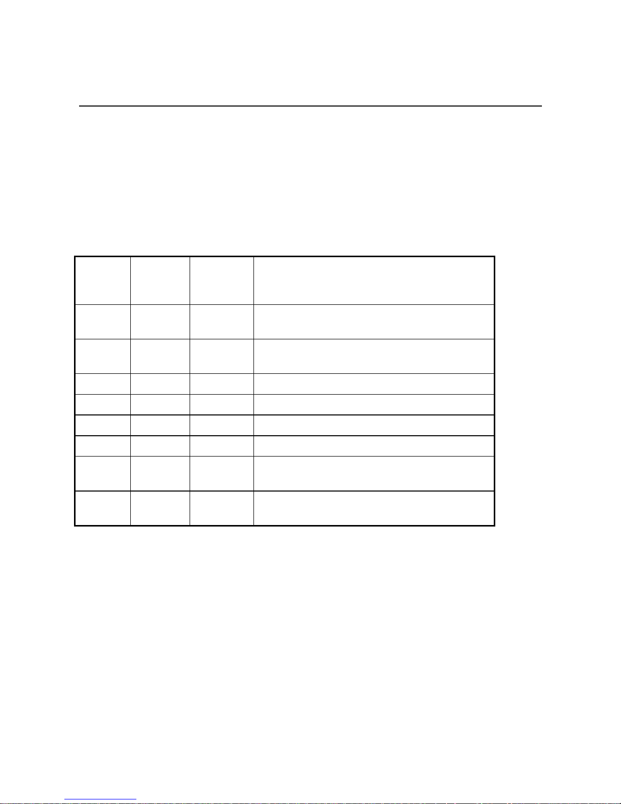
The cable shown in Figure 2-2 or Figure 2-3 may be used to connect most ASCII terminals or
serial printers to NDS/5000 serial ports. The cable shown in Figure 2-4 or Figure 2-5 may be
used to connect modems to the NDS/5000. Modems should be configured to switch their
Connecting Devices to the NDS10
carrier detect signal (CD) on and off in response to making and breaking telephone
connections. This insures that the NDS/5000 terminates users’ sessions when they
disconnect. Figure 2-6 shows a 3-wire cable.
Pin 1
RJ-45 Plug Pin
Number
1 DCD
2 RTS
3 SG
6 SG
4 TXD
5 RXD
7 CTS
8 DTR
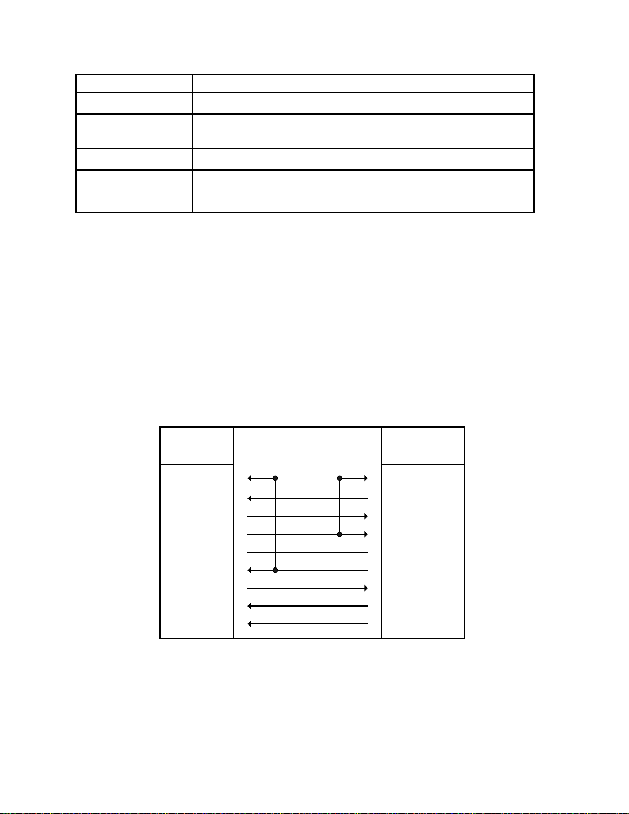
Figure 2-2: RJ-45 to DB-25 Terminal Cable
DB-25 Plug Pin
Number/Signal
20 DTR
5 CTS
7 SG
3 RXD
2 TXD
4 RTS
8 DCD
6 DSR
Installing the Hardware 11
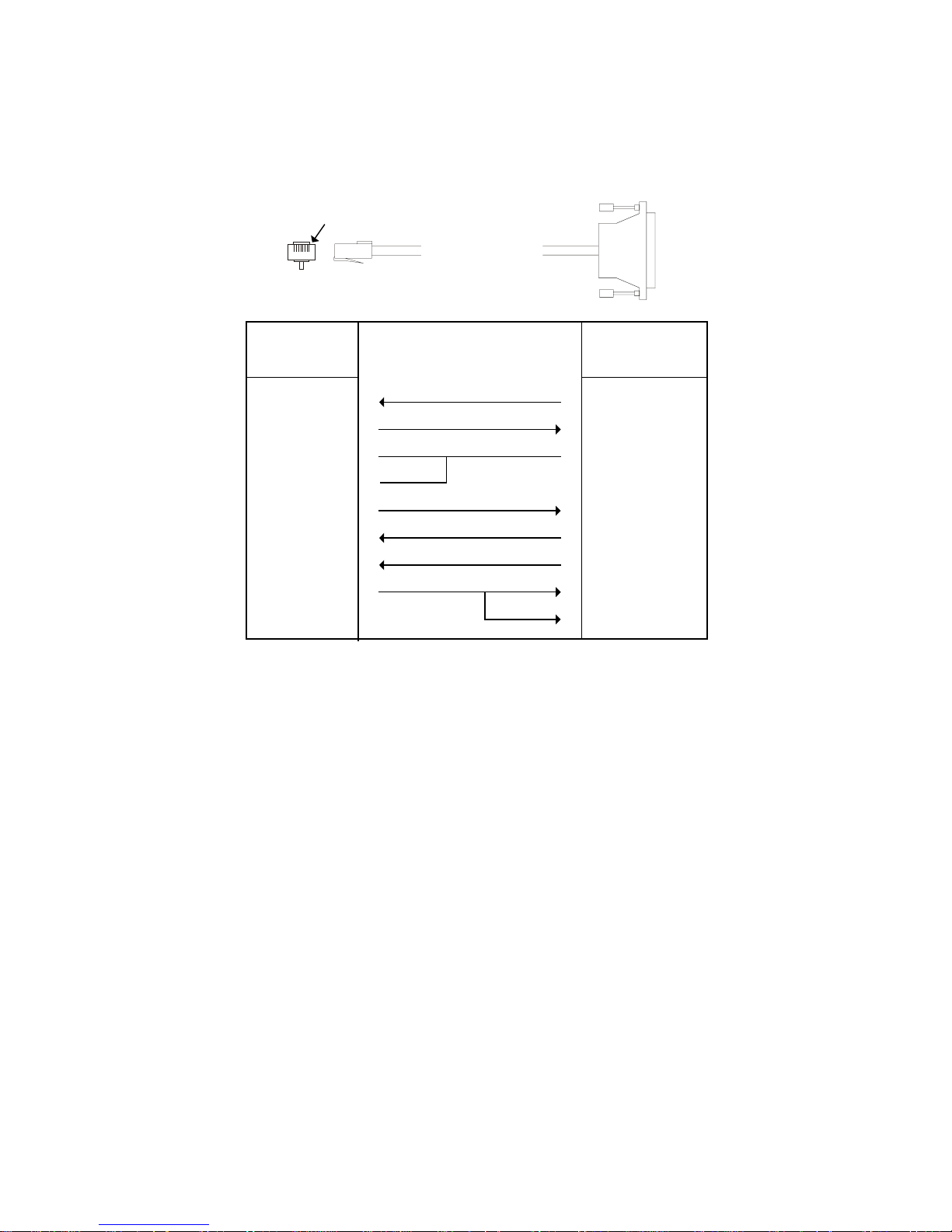
Pin 1
RJ-45 Plug Pin
Number
1 DCD
2 RTS
3 SG
6 SG
4 TXD
5 RXD
7 CTS
8 DTR
Figure 2-3: RJ-45 to DB-9 Terminal Cable
Pin 1
DB-9 Plug Pin
Number/Signal
4 DTR
8 CTS
5 SG
2 RXD
3 TXD
7 RTS
1 DCD
6 DSR
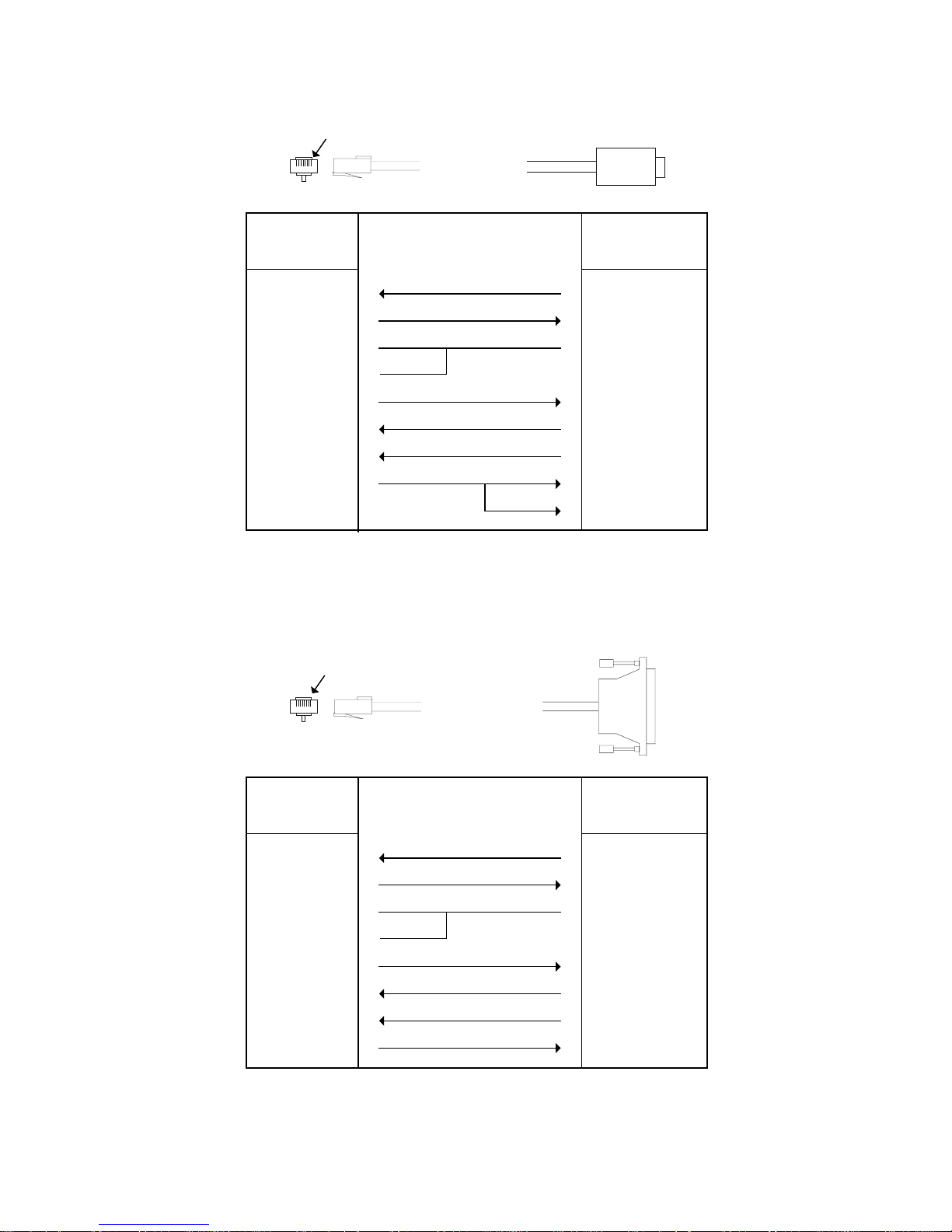
RJ-45 Plug Pin
Number
1 DCD
2 RTS
3 SG
6 SG
4 TXD
5 RXD
7 CTS
8 DTR
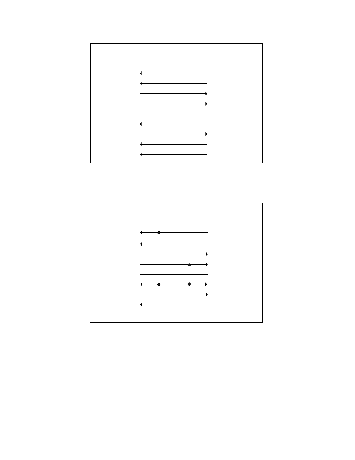
Figure 2-4: RJ-45 to DB-25 Modem Cable
Connecting Devices to the NDS12
DB-25 Plug Pin
Number/Signal
8 DCD
4 RTS
7 SG
2 TXD
3 RXD
5 RTS
20 DTR

Pin 1
RJ-45 Plug Pin
Number
1 DCD
2 RTS
3 SG
6 SG
4 TXD
5 RXD
7 CTS
8 DTR
DB-9 Plug Pin
Number/Signal
1 DCD
7 RTS
5 SG
3 TXD
2 RXD
8 RTS
4 DTR
Figure 2-5: RJ-45 to DB-9 Modem Cable
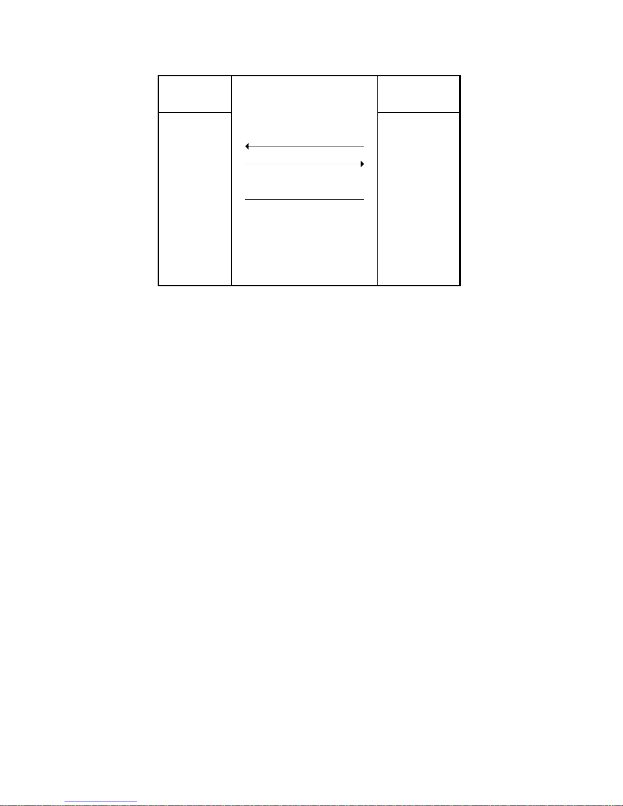
The NDS/5000 does not require the use of all 8 wires. Only the RX, TX, and GND signals are
essential. DTR/DSR and RTS/CTS are only necessary for flow control. DCD (pin 1) is
normally not required. Figure 2-6 shows a minimal 3-wire cable using only RX (pin 5, data
in), TX (pin 4, data out), and GND (pin 3, ground).
RJ-45 Pin
Number
1 DCD
2 RTS
3 SG
4 TXD
5 RXD
6 SG
7 CTS
8 DTR
DB-25 Pin
Number/Signal
7 SG
3 RXD
2 TXD
Figure 2-6: RJ-45 to DB-25 3-Wire Terminal Cable
Installing the Hardware 13
RJ-45 to DB-25 or DB-9 adapters may be used with RJ-45 cables to create the cable
configurations shown in Figure 2-2 through Figure 2-6. In most cases, you use “straight
through” RJ-45 cables. If you use “crossover” RJ-45 cables, the RJ-45 pins will be reversed.
Figure 2-7 and Figure 2-8 illustrate the difference between the two types, when constructed
with flat 8-conductor wire.
pin 1
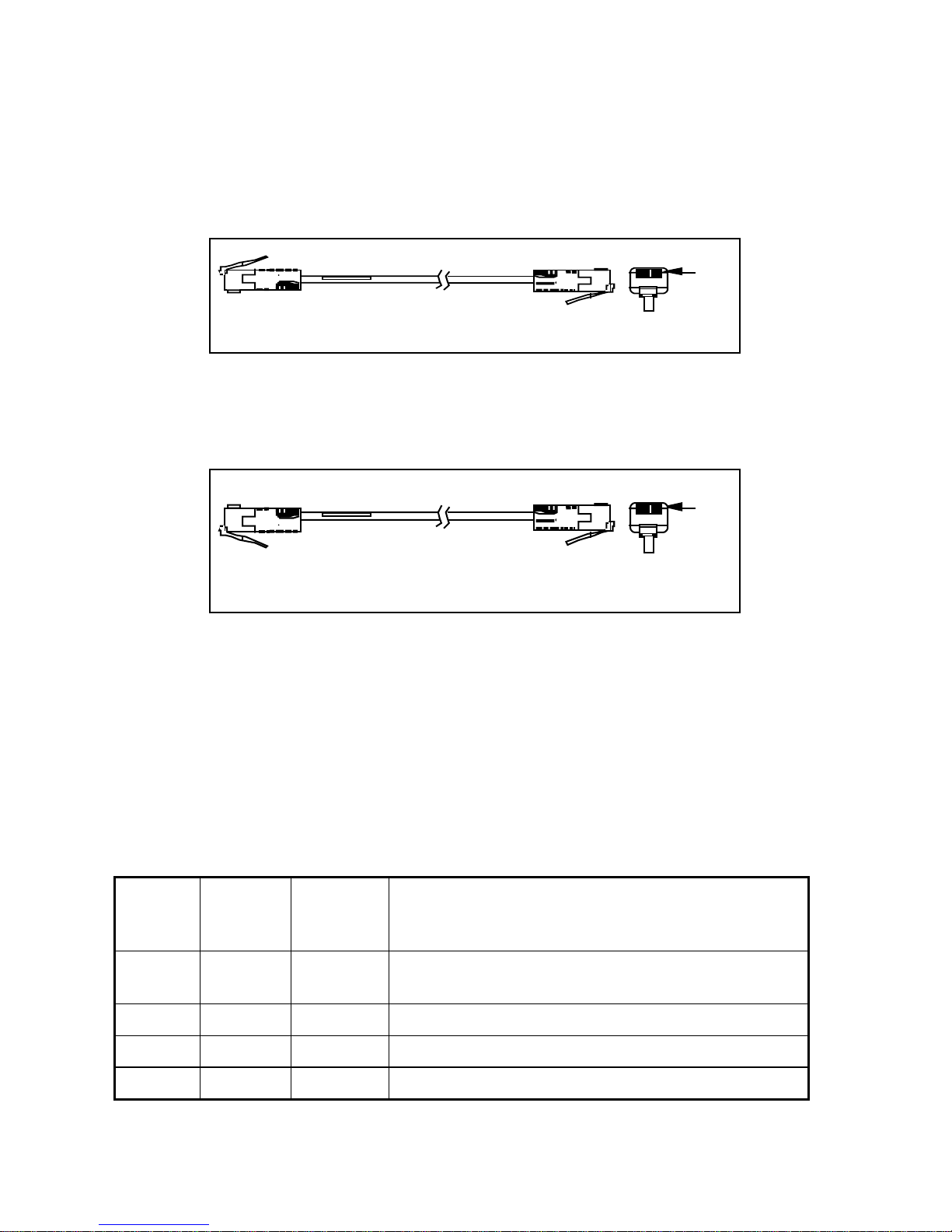
Figure 2-7: RJ-45 to RJ-45 Straight-through Cable
pin 1
Figure 2-8: RJ-45 to RJ-45 Crossover Cable
NDS/6000 RS-232 Operation
The NDS/6000 port server family uses an EIA-232 data terminal equipment (DTE) pinout
on the DB-9 serial ports. Table 2-9 lists the pinouts of the DB-9 ports used for EIA-232 serial
communications.
DB-9
Pin
Number
1 DCD I Signals module that remote device has a valid
2 RX I Serial data in, from remote device to NDS
3 TX O Serial data out, from NDS to remote device
4 DTR O Signals remote device that NDS is attached and
RS-232
Name Direction Signal Function
connection
Connecting Devices to the NDS14
powered on
5 GND Signal ground
6 DSR I Signals module that remote device is attached and
powered on
7 RTS O Flow control, to enable remote device to send data
8 CTS I Flow control, to enable NDS to send data on TX
9 RI I Ring Indicator
Table 2-9: EIA-232 DB-9 Pinouts
Figure 2-10, Figure 2-11, and Figure 2-12 show cable diagrams for three common
configurations. The cable shown in Figure 2-11 may be used to connect modems to the
NDS/6000. Modems should be configured to switch their carrier detect signal (CD) on and
off in response to making and breaking telephone connections. This insures that the
NDS/6000 terminates user sessions when they disconnect. The cable shown in Figure 2-10
can be used to connect a DB-9 terminal (or standard PC COM) port directly to the
NDS/6000. The DB-9 to DB-9 terminal cable diagrammed in Figure 2-12 is a standard NULL
modem connector, readily available in retail outlets. DB-9 to DB-9 modem cables (not
diagrammed) require no special pinouts and use a straight-through cable. A 3-wire cable is
shown in Figure 2-13.
DB-9 Pin
Number
1 DCD
2 RX
3 TX
4 DTR
5 GND
6 DSR
7 RTS
8 CTS
9 RI
Figure 2-10: DB-9 to DB-25 Terminal Cable
DB-25 Pin
Number/Signal
8 DCD
2 TX
3 RX
6 DSR
7 GND
20 DTR
5 CTS
4 RTS
22 RI
Installing the Hardware 15
DB-9 Pin
Number
DB-25 Pin
Number/Signal
1 DCD
2 RX
3 TX
4 DTR
5 GND
6 DSR
7 RTS
8 CTS
9 RI
Figure 2-11: DB-9 to DB-25 Modem Cable
DB-9 Pin
Number
1 DCD
8 DCD
3 RX
2 TX
20 DTR
7 GND
6 DSR
4 RTS
5 CTS
22 RI
DB-9 Pin
Number
4 DTR
2 RX
3 TX
4 DTR
5 GND
6 DSR
7 RTS
8 CTS
9 RI
3 TX
2 RX
1 DCD
5 GND
6 DSR
8 CTS
7 RTS
9 RI
Figure 2-12: DB-9 to DB-9 Terminal Cable
The NDS/6000 does not require the use of all 9 wires. Only the RX, TX, and GND signals are
essential. DTR/DSR and RTS/CTS are only necessary for flow control. DCD (pin 1) is
normally not required and RI (pin 9) is only required for modems that need a ring indicator.
Figure 2-13 shows a minimal 3-wire cable using only RX (pin 2, data in), TX (pin 3, data out),
and GND (pin 5, ground).
Connecting Devices to the NDS16
DB-9 Pin
Number
DB-25 Pin
Number/Signal
1 DCD
2 RX
3 TX
4 DTR
5 GND
6 DSR
7 RTS
8 CTS
9 RI
8 DCD
2 TX
3 RX
6 DSR
7 GND
20 DTR
5 CTS
4 RTS
22 RI
Figure 2-13: DB-9 to DB-25 3-wire Terminal Cable
Installing the Hardware 17
RS-422/485 Operation
Unlike RS-232, the RS-485 and RS-422 specifications do not have a standard set of pinouts.
In general, whenever you use RS-422/485 devices you will need to make custom cables. The
NDS DB-9 pinouts for RS-422 /RS-485 mode are shown in Table 2-14. The RJ-45 pinouts are
shown in Table 2-15.
Pin#Name Direction
1Not used
2 RXB/RX+ Input
3 TXB/TX+ Output
4Not used
5GND
6Not used
7TXA/TX-Output
8 RXA/RX- Input
9Not used
Table 2-14: DB-9 Pinouts for RS-422 and RS-485
Pin # Name Direction
1Not used
2TXA/TX-Output
3GND
4 TXB/TX+ Output
5 RXB/RX+ Input
6GND
7 RXA/RX- Input
8Not used
Table 2-15: RJ-45 Pinouts for RS-422 and RS-485
RS-485 2-wire mode uses the same pinouts, but the receive and transmit pairs should be
externally shorted together in the connector (TXA shorted to RXA and TXB shorted to RXB).
Note that some RS-422 and RS-485 devices refer to the differential pair of signals that make
up the transmit and receive lines as “-” and “+“ instead of the standard “A” and “B”. In
Connecting Devices to the NDS18

most cases, the “-” signal corresponds to the “A” signal and the “+” signal corresponds to
the “B” signal, but some devices reverse this. Refer to the chapter on Using RS-422 and RS-
485 Devices for more information on wiring and using 2-wire and 4-wire RS-422/485
networks with the NDS.
Installing the Hardware 19

Ethernet LAN
The NDS is connected to your LAN using an Ethernet port. The Ethernet port on the NDS is
a standard 10/100 Base-TX RJ-45 jack. It can be connected to an Ethernet hub/switch via a
standard, straight-through Ethernet cable.
Figure 2-16: Network Topology Example
The switch versions of the NDS have four 10/100 Base-TX Ethernet ports. These ports are all
interchangeable. Any port can be used to either connect to a hub/switch or to a network
device (auto MDI/MDIX).
The fourth Ethernet port may optionally be a MT-RJ 100 Base-FX Ethernet port (not available
on 8 and 16 port models).
Connecting Devices to the NDS20

Starting the NDS
When the NDS is powered up, the LEDs will flash to indicate normal operation. The
following LED colors and patterns will be displayed during normal startup, if no errors are
detected.
• Status LED – initially this LED will be yellow, but will quickly turn green. If the status
LED is solid green, then the NDS doesn’t have a permanent IP address and is trying to
obtain one from a DHCP server. If the LED is blinking green, it means the NDS has
obtained an IP address and is ready to use. Red indicates a fatal error.
• Ethernet LEDs – these LEDs will either be off or green. A green LED means that a good
Ethernet link has been established and the unit is on the network. The LED will blink
green to show network activity.
• Serial port LEDs – these LEDs will normally be either off or green. Off indicates a port
that is not in use. Green indicates a port that is in use. The green LED will blink when
data is transmitted or received. It will blink 2 times per second when data is
continuously transmitted or received.
If any of the LEDs turn red, an error condition was detected. For a full description of the
LED patterns, see Troubleshooting.
Installing the Hardware 21


Chapter 3: Using RS-422 and RS-485
Devices
The NDS can be used to communicate with RS-422 and RS-485 devices. This chapter
describes connecting these devices and configuring the NDS to communicate in this mode.
Connecting RS-422/485 Devices
RS-422 and RS-485 modes are very similar, except that in RS-422 mode the transmitter
remains enabled at all times; in RS-485 mode, the transmitter is disabled automatically when
no data is being transmitted. Consequently, RS-422 devices must be connected using a fourwire cable (i.e. with separate transmit and receive pairs). RS-485 devices may be connected
with either two-wire or four-wire cables.
You can connect two RS-422/485 devices with a point-to-point connection, or more than two
RS-485 devices in a bus configuration.
The only legal RS-485 cabling topology is a bus topology (including point-to-point
connections)! All other topologies are expressly forbidden by the RS-485 specification. This
includes the following illegal configurations:
• Connecting cables in any type of star topology (regardless of whether or not devices are
attached to the ends of the cables). This includes using star-based patch panels or any
other method that splits the physical cable off into multiple segments.
• Connecting RS-485 devices to the bus using cable stubs of any length
Due to the resilience of the RS-485 signaling specification, some of these illegal topologies
may work in certain configurations. However, changing factors such as cable length, baud
rate, number of devices, bus loading, etc. may cause such configurations to fail sporadically
or to stop communicating entirely. The only topology guaranteed to work in all cable
configurations is a properly terminated bus topology.
RS-422/485 Point-to-point Configuration
Point-to-point connections can be established between two RS-422 devices, an RS-422 and an
RS-485 device, or two RS-485 devices. Figure 3-1 shows a four-wire, point-to-point
connection between two devices.
Using RS-422 and RS-485 Devices 23

RS-422/485
T
RS-422/485
TXA TXB RXA RXB
GND
XA TXB RXA RXB
GND
GND
Figure 3-1: RS-422/485 point-to-point connection
Notice the termination on each end of the connection. The receiving end of the wire should
be terminated with a resistance equal to the wire's characteristic impedance, generally 100120 ohms.
RS-422/485 Bus Configurations
More than two RS-422/485 devices can be connected in a bus configuration. You can connect
one RS-422 and several RS-485 devices on a bus or you can connect several RS-485 devices
on a bus, but you cannot connect more than one RS-422 device on a single bus. If your
configuration includes an RS-422 device, you must use a four-wire connection.
Configurations including only RS-485 devices can use either two-wire or a four-wire
communication.
When RS-422 and/or RS-485 devices are connected to a bus, they operate as one master and
one or more slaves. In all configurations that include an RS-422 device, the RS-422 device is
the master and the RS-485 devices are slaves.
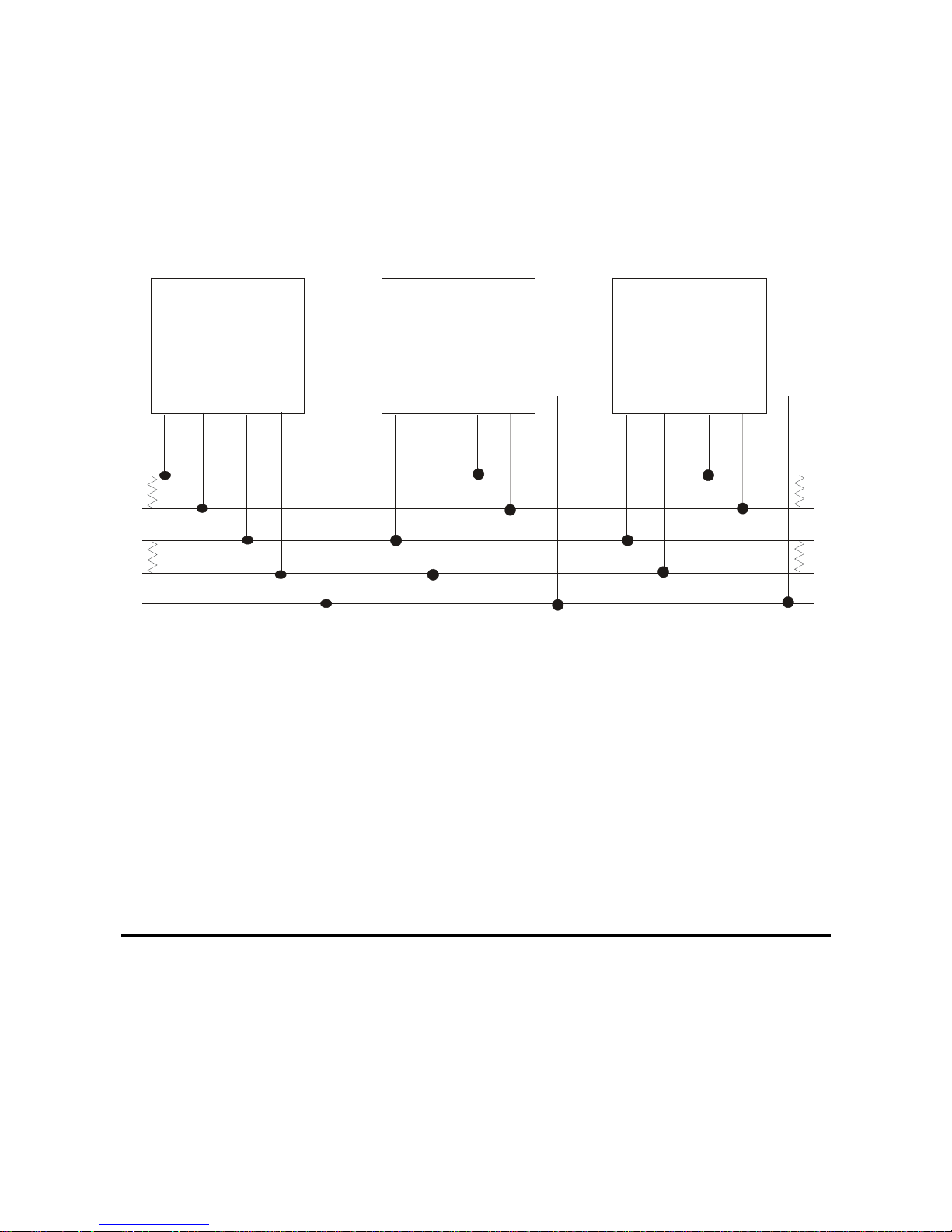
Two-Wire System
In two-wire communication, all devices share the same pair of wires to both transmit and
receive. All the devices connected to a two-wire system must be RS-485 devices. Figure 3-2
shows a typical two-wire system.
Connecting RS-422/485 Devices24

MA
S
T
S
TER
LAVE
SLAVE
RS-485
TXA TXB RXA RXB
GND
RS-485
TXA TXB RXA RXB
GND
GND
RS-485
XA TXB RXA RXB
GND
Figure 3-2: Two-wire RS-485 System
In the two-wire system diagrammed in Figure 3-2, one pair of transmit and receive lines
(TXA and RXA) are connected to a single wire and the other pair of transmit and receive
lines (TXB and RXB) are connected to the second wire. The device that is designated as the
master manages the traffic on the lines.
As shown in the above diagram, the pair of transmit/receive lines needs to be terminated
with 120 ohms at each end of the bus.
Using RS-422 and RS-485 Devices 25
Four-Wire Systems
S
T
S
In four-wire communication, there are two pairs of transmit and receive lines, allowing full
duplex communication. In most four-wire systems, an RS-422 device will serve as the master
with several RS-485 devices as slaves. However, an RS-422 device is not required; an RS-485
device can serve as the master. Figure 3-3 shows a typical four-wire system.
TER
MA
RS-422/485
TXA TXB RXA RXB
GND
Figure 3-3: Four-wire RS-422/485 System
In most configurations, the device that is designated as the master will be an RS-422 device
that constantly drives the transmit lines.
TXA TXB RXA RXB
LAVE
RS-485
GND
GND
SLAVE
RS-485
XA TXB RXA RXB
GND
Both pairs of lines on the multi-drop wire must be terminated at each end of the bus with a
resistance equal to the wire's characteristic impedance, generally 120 ohms. If the RX data
pins are not terminated at all and have nothing attached, they may be susceptible to cross
talk. Data from other lines on this serial port, or from other nearby ports, may be coupled
back onto the unterminated receive lines. You should attach a simple 100- or 120-ohm
termination resistor between the lines to avoid this.
Using the NDS in RS-422 or RS-485 Mode
The NDS ports can function as any of the devices in any of the configurations described
above. The NDS can be connected to either an RS-422 or an RS-485 device in a point-to-point
configuration. Or the NDS can be connected to a two-wire or four-wire bus, as either a
master or a slave, and can communicate in either RS-422 or RS-485 mode. Typically, a single
NDS is connected to the bus and functions as the master, but this is determined by the
application. The ports are configured for RS-232, RS-485 or RS-422 via software. Refer to the
NDS Administrator’s Guide.
Using the NDS in RS-422 or RS-485 Mode26

Chapter 4: Troubleshooting
The NDS has several LED indicators: Unit Status, Serial ports, and Ethernet.
The LEDs use red, yellow, and green blinking combinations to indicate the status of each of
the NDS’s major components.
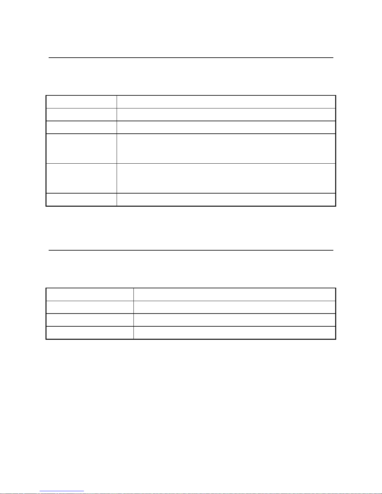
Status LED
The status LED indicates the overall status of the NDS. See Table 4-1.
Status LED Condition Meaning
Solid Green The unit is running, but it needs an IP address. It is trying to
obtain one from DHCP/BOOTP.
Blinking Green The unit has an IP address and is operating normally
Alternating Green/Red If the “reset” button is being held in, this LED sequence means
that the factory default configuration is about to be restored. If
you do not want to restore the factory default, release the
button before the sequence changes to Green/Yellow.
Otherwise this means a serious system error occurred. See the
system log for more details.
Alternating Green/Yellow If the “reset” button is being held in, this LED sequence means
that the factory default configuration was restored. You may
release the button.
Otherwise, this means that the current configuration is corrupt
and that the factory default configuration is being used.
Blinking Yellow The unit is booting.
Solid Red Fatal error.
Off No power, or the unit is inoperative
Table 4-1: Status LED Conditions
Troubleshooting 27
Serial Port LEDs
Each serial port has a Port LED that describes port activity. Table 4-2 describes the various
Port LED states.
Port LED Condition Meaning
Off Port is closed or no power.
Solid Green Port is open, but idle
Blinking Green Port is open, and data is being transmitted or received. When data is
being continuously transferred, this LED will blink approximately 2
times per second.
Red Blinks Data errors will cause periodic red blinks. Persistent red blinks may
imply a configuration problem (incorrect baud rate, parity settings,
etc.)
Solid Red Port hardware has failed
Table 4-2: Port LED Conditions
Ethernet LEDs
Each Ethernet port has one LED that describes the state of the network connection on that
port. Table 4-3 describes the various Ethernet LED states.
Ethernet LED Condition Meaning
Solid Green Ethernet link is good
Green Blink Network traffic was detected
Off The Ethernet cable is bad or not connected
Table 4-3: Ethernet LED Condition
Serial Port LEDs28

Appendix: Specifications
NDS Hardware Specifications
• ARM7 50MHz CPU (2-4 port units) or ARM9 166MHz CPU (8-16 port units)
• 512K to 8Mbytes in-circuit boot flash and program memory
• 8 to 64 Mbytes SDRAM
• 10/100 Mbps Ethernet connection over 10/100 Base-TX or 100 Base-FX physical lines
• Two to sixteen asynchronous serial ports with modem control and surge suppression
• Asynchronous port data rates of up to 230.4 Kbps
• DB-9 or RJ-45 physical connectors
• Serial ports software configurable for RS-232 or RS-422/RS-485
• External or Internal 110-240 VAC power supply provides +5V DC regulated to NDS
• Status LEDs for each port
Environmental Specifications
• Operating temperature range: 0 to 50°C
• Storage temperature range: -10 to 70°C
• Humidity range: 10% to 90% noncondensing
Product Dimensions
The NDS models measure:
2-4 port models – plastic enclosures
6 inches x 5.65 inches x 2.0 inches (152 mm x 144 mm x 51 mm)
8-16 port models – plastic enclosures
12 inches x 5.6 inches x 1.9 inches (305 mm x 143 mm x 48 mm)
8-16 port models – rack mount enclosures
17.0 inches x 5.8 inches x 1.7 inches (435 mm x 148 mm x 44 mm)
With mounting brackets, total width is 18.9 inches (482 mm)
Index 29

Model Numbers
NDS/5102 Two Ports, RJ-45, one 10/100 Base-TX port
NDS/5202 Two Ports, RJ-45, four-port 10/100 Base-TX Ethernet switch
NDS/5302 Two Ports, RJ-45, three 10/100 Base-TX Ethernet, one 100 Base-FX Fiber
NDS/5104 Four Ports, RJ-45, one 10/100 Base-TX port
NDS/5204 Four Ports, RJ-45, four-port 10/100 Base-TX Ethernet switch
NDS/5304 Four Ports, RJ-45, three 10/100 Base-TX Ethernet, one 100 Base-FX Fiber
NDS/6102 Two Ports, DB-9, one 10/100 Base-TX port
NDS/6202 Two Ports, DB-9, four-port 10/100 Base-TX Ethernet switch
NDS/6302 Two Ports, DB-9, three 10/100 Base-TX Ethernet, one 100 Base-FX Fiber
NDS/6104 Four Ports, DB-9, one 10/100 Base-TX port
NDS/6204 Four Ports, DB-9, four-port 10/100 Base-TX Ethernet switch
NDS/6304 Four Ports, DB-9, three 10/100 Base-TX Ethernet, one 100 Base-FX Fiber
NDS/5008 Eight Ports, RJ-45, four-port 10/100 Base-TX switch, plastic enclosure
NDS/5008-RM Eight Ports, RJ-45, four-port 10/100 Base-TX switch, Rackmount
NDS/6008 Eight Ports, DB-9, four-port 10/100 Base-TX switch, plastic enclosure
NDS/6008-RM Eight Ports, DB-9, four-port 10/100 Base-TX switch, Rackmount
NDS/5016 Sixteen Ports, RJ-45, four-port 10/100 Base-TX switch, plastic enclosure
NDS/5016-RM Sixteen Ports, RJ-45, four-port 10/100 Base-TX switch, Rackmount
Ethernet cabling specifications
This section describes guidelines for using 10/100 Base-TX twisted-pair cabling:
• Recommended cable is category 5 (CAT5 or CAT5E) unshielded solid copper twisted
pair
• Ethernet cable pairs must be properly twisted: pins 1 and 2 must be a twisted pair, and
pins 3 and 6 must be a twisted pair
• Maximum distance of a segment—from concentrator to node—is 100 meters (328 feet)
• Maximum of 5 segments between any two nodes
Index30

Power Requirements
Units in plastic enclosures use an external power supply. The Rackmount units have an
internal power supply.
Models Input Power
2-4 port units 100-240VAC, 50-60HZ 0.3A 5V 2.0A
8-16 port units, plastic enclosure 100-240VAC, 50-60HZ 0.7A 5V 4.0A
8-16 port units, rackmount 85-264VAC, 47-63HZ N/A
0.5A (115VAC), 0.25A (240VAC)
Output Power
Index 31

Index
1
10/100 Base-TX, cabling specifications, 30
3
3-wire diagram
NDS/5000, 13
NDS/6000, 16
3-wire terminal, cable diagram, DB-9 to DB-25, 17
3-wire terminal, cable diagram, RJ-45 to DB-25, 13
A
asynch port
specifications, 29
B
bus configuration, RS-422/485, 24
C
cable diagram
3-wire terminal, DB-9 to DB-25, 17
3-wire terminal, RJ-45 to DB-25, 13
modem, DB-9 to DB-25, 16
modem, RJ-45 to DB-25, 13
modem, RJ-45 to DB-9, 13
NDS/5000, 14
terminal, DB-9 to DB-25, 15
terminal, DB-9 to DB-9, 16
terminal, RJ-45 to DB-25, 11
terminal, RJ-45 to DB-9, 12
cables, 10
cables, RJ-45 to DB adapter, 14
cabling, specifications, 30
carrier detect signal (CD), 10
configuration planning, 7
connector wiring
NDS/5000, 10
NDS/6000, 15
D
data communication equipment (DCE), 10
data terminal equipment (DTE), 10
DB-9 serial port
diagram, 8
DB-9 serial ports
pinouts, 14
DB-9 to DB-25 3-wire terminal cable diagram, 17
DB-9 to DB-25 modem cable diagram, 16
DB-9 to DB-25 terminal cable diagram, 15
DB-9 to DB-9 terminal cable diagram, 16
DCE, 10
default configuration, 9
DTE, 10
DTE pinout
NDS/5000, 10
NDS/6000, 14
E
EIA-232, 10, 14
ethernet network
cabling specifications, 30
F
factory default configuration, 9
front panel, diagram, 8
I
installation, hardware, 7
L
LAN
connecting NDS to, 20
LAN port
description, 20
LED
diagram, 9
overview, 27
start up and self-test, 21
Index32

M
modem signals
CD, 15
CD, 10
modem, cable diagram, DB-9 to DB-25, 16
modem, cable diagram, RJ-45 to DB-25, 13
modem, cable diagram, RJ-45 to DB-9, 13
P
panel, diagram, 8
pinouts
NDS/5000, 10
NDS/6000, 14
RS-422, 18
RS-485, 18
point-to-point connection, RS-422/485, 23
port, DB-9
diagram, 8
pinout, 14
port, RJ-45
diagram, 8
pinout, 10
R
red LED, 21
restoring default configuration, 9
RJ-45 cable diagram, 14
RJ-45 port
diagram, 8
RJ-45 ports, pinouts, 10
RJ-45 serial port
diagram, 8
RJ-45 to DB adapters cable, 14
RJ-45 to DB-25 3-wire terminal cable diagram, 13
RJ-45 to DB-25 modem cable diagram, 13
RJ-45 to DB-25 terminal cable diagram, 11
RJ-45 to DB-9 modem cable diagram, 13
RJ-45 to DB-9 terminal cable diagram, 12
RS-232, 10, 14
RS-422, 23
pinouts, 18
RS-422 and RS-485 comparison, 23
RS-422/485 topology, 23
RS-485, 23
pinouts, 18
S
self-test, 21
sessions, terminating on modem disconnect, 15
specifications, 29
start up, 21
T
terminal, cable diagram, DB-9 to DB-25, 15
terminal, cable diagram, DB-9 to DB-9, 16
terminal, cable diagram, RJ-45 to DB-25, 11
terminal, cable diagram, RJ-45 to DB-9, 12
termination
RS-422/485 four-wire bus configuration, 26
RS-422/485 point-to-point connection, 24
RS-422/485 two-wire bus configuration, 25
topology, RS-422/485, 23
troubleshooting
LED indicators, 27
twisted-pair, cabling specifications, 30
W
wiring, 10
Index 33
 Loading...