

Sys Tec Electronic GW-003 System Manual

system house for distributed automation
CAN-Ethernet Gateway
GW-003
Systems Manual
Edition April 2007

CAN – Ethernet Gateway
© SYS TEC electronic GmbH 2007 L-1032e_9
In this manual are descriptions for copyrighted products, which are not explicitly
indicated as such. The absence of the trademark (™) and copyright (©) symbols
does not infer that a product is not protected. Additionally, registered patents and
trademarks are similarly not expressly indicated in this manual
The information in this document has been carefully checked and is believed to be
entirely reliable. However, SYS TEC electronic GmbH assumes no responsibility
for any inaccuracies. SYS TEC electronic GmbH neither gives any guarantee nor
accepts any liability whatsoever for consequential damages resulting from the use
of this manual or its associated product. SYS TEC electronic GmbH reserves the
right to alter the information contained herein without prior notification and
accepts no responsibility for any damages, which might result.
Additionally, SYS TEC electronic GmbH offers no guarantee nor accepts any
liability for damages arising from the improper usage or improper installation of
the hardware or software. SYS TEC electronic GmbH further reserves the right to
alter the layout and/or design of the hardware without prior notification and
accepts no liability for doing so.
© Copyright 2006 SYS TEC electronic GmbH, D-07973 Greiz/Thuringia. Rights
- including those of translation, reprint, broadcast, photomechanical or similar
reproduction and storage or processing in computer systems, in whole or in part are reserved. No reproduction may occur without the express written consent from
SYS TEC electronic GmbH.
EUROPE NORTH AMERICA
Address: SYS TEC electronic GmbH
August-Bebel-Str. 29
D-07973 Greiz
GERMANY
PHYTEC America LLC
203 Parfitt Way SW, Suite G100
Bainbridge Island, WA 98110
USA
Ordering
Information:
+49 (0) 36 61 / 62 79-0
info@systec-electronic.com
1 (800) 278-9913
info@phytec.com
Technical
Support:
+49 (0) 36 61 / 62 79-0
support@systec-electronic.com
1 (800) 278-9913
support@phytec.com
Fax: +49 (0) 36 61 / 62 79-99 1 (206) 780-9135
Web Site: http://www.systec-electronic.com http://www.phytec.com
9th Edition April 2007

Contents
© SYS TEC electronic GmbH 2007 L-1032e_9
Table of Contents
1 Introduction......................1
1.1 Fundamentals ...............................................................................1
1.2 Application Fields........................................................................2
1.2.1 Connecting Two CAN Networks over Ethernet.............2
1.2.2 Remote Diagnostics and Configuration of CAN
Networks .........................................................................
4
1.3 Delivery Contents.........................................................................5
2 Technical Data..................7
3 Getting Started.................9
3.1 Power Supply ...............................................................................9
3.2 Network Connection ....................................................................9
3.2.1 Connecting to a CAN Bus...............................................9
3.2.2 Ethernet Connection......................................................10
3.2.3 RS-232 Interface ...........................................................11
3.3 Device Status Display ................................................................12
3.4 Switches......................................................................................13
3.5 Initial Setup and Operation ........................................................14
3.5.1 Standard Configuration.................................................14
3.5.2 Initial Configuration using the RS-232 Interface..........15
3.5.3 Configuration and Operation using Telnet ...................22
4 Device Functions ............23
4.1 Overview....................................................................................23
4.2 Interfaces....................................................................................24
4.2.1 Fundamentals ................................................................24
4.2.2 UDP/TCP Server Interface............................................26
4.2.3 UDP/TCP Client Interface ............................................28
4.2.4 CAN Interface...............................................................31
4.2.5 LED Interface Status Display .......................................33
4.3 Filtering......................................................................................34
4.3.1 Concept of Message Filtering .......................................34
4.3.2 Input Filter.....................................................................34
4.3.3 Output Filter..................................................................34
4.3.4 Filter Description (Syntax)............................................35
4.4 File System.................................................................................38
4.4.1 Structure........................................................................38
4.4.2 Data Storage in EEPROM.............................................39
4.5 Command Set Description .........................................................40
4.5.1 cd...................................................................................40
4.5.2 ls....................................................................................40
4.5.3 mkif ...............................................................................41

CAN – Ethernet Gateway
© SYS TEC electronic GmbH 2007 L-1032e_9
4.5.4 mem............................................................................... 42
4.5.5 rm.................................................................................. 43
4.5.6 write ..............................................................................43
4.5.7 cat.................................................................................. 44
4.5.8 sync ............................................................................... 44
4.5.9 version...........................................................................45
4.5.10 exit................................................................................. 45
4.5.11 reset...............................................................................45
4.5.12 ipcfg ..............................................................................46
4.5.13 siocfg............................................................................. 47
5 Gateway Configuration. 49
5.1 Fundamentals............................................................................. 49
5.2 Example for a Customer-Specific Configuration Script............50
5.3 Creating a Configuration Script................................................. 51
5.4 Resetting the Device to its Standard Configuration................... 52
5.5 Assigning Passwords .................................................................52
6 Error Handling ..............53
6.1 CAN-Ethernet Gateway Error Signals....................................... 53
6.2 Error Indication under Windows ...............................................56
6.3 Error Messages over CAN......................................................... 56
7 Software Support........... 59
7.1 Interfacing the CAN-Ethernet Gateway to a PC........................ 59
7.2 Driver Installation under Windows............................................ 59
7.3 Dynamic Linked Library EthCan.Dll........................................61
7.3.1 The Concept of the EthCan.Dll .................................... 61
7.3.2 EthCan.Dll Function Interface...................................... 62
7.3.2.1 EthCanGetVersion......................................... 63
7.3.2.2 EthCanInitHardware...................................... 64
7.3.2.3 EthCanDeinitHardware .................................69
7.3.2.4 EthCanReadCanMsg .....................................73
7.3.2.5 EthCanWriteCanMsg .................................... 76
7.3.2.6 EthCanGetStatus............................................ 78
7.3.2.7 EthCanGetConnectionState........................... 80
7.3.2.8 EthCanResetCan............................................ 82
7.3.3 Error Code Description................................................. 84
7.3.4 CAN Error Code Description .......................................88
7.3.5 Using the DLL Functions .............................................90
7.3.5.1 Demo project .................................................90
7.3.5.2 Starting the Demo Program........................... 91
8 Updating the device Firmware........................................................93
8.1 Preparations................................................................................ 93
8.2 Firmware download ................................................................... 94

Contents
© SYS TEC electronic GmbH 2007 L-1032e_9
Index.........................................97

CAN – Ethernet Gateway
© SYS TEC electronic GmbH 2007 L-1032e_9
Index of Figures
Figure 1: Application Example #1: Transparent Connection of two CAN
Networks using Intranet/Ethernet..............................................
3
Figure 2: Application Example #2: Remote Diagnostics of CAN
Networks on a Service Computer over the Internet ..................
5
Figure 3: View of the CAN-Ethernet Gateway......................................... 8
Figure 4: HyperTerminal Configuration (1)............................................ 15
Figure 5: HyperTerminal Configuration (2)............................................ 16
Figure 6: CAN-Ethernet Gateway Start Message................................... 16
Figure 7: Sending a Configuration File via HyperTerminal................... 19
Figure 8: Selecting a Configuration File................................................. 19
Figure 9: Successful Transmission of a Configuration File, Terminate
with Crtl+D..............................................................................
20
Figure 10: Finishing the Configuration..................................................... 20
Figure 11: Verifying the Selected Configuration...................................... 21
Figure 12: CAN-Ethernet Gateway Functional Overview........................ 23
Figure 13: File System Structure............................................................... 38
Figure 14: Hardware Parameter Structure Overview................................ 65
Figure 15: CAN-Ethernet-Gateway Transfer Protocols............................ 65
Figure 16: CAN-Ethernet Gateway Connection Status ............................ 67
Figure 17: CAN Message Structure .......................................................... 73
Figure 18: The CAN timestamp structure................................................. 74
Figure 19: CAN-Status Structure.............................................................. 78
Figure 20: MemTool software................................................................... 94
Figure 21: Memory sectors of the CAN-Ethernet Gateway...................... 95
Figure 22: Memory areas and sector assignment...................................... 95

Index of Tables
© SYS TEC electronic GmbH 2007 L-1032e_9
Index of Tables
Table 1: CAN Connector Pin Assignment.............................................10
Table 2: Ethernet Connector Pin Assignment........................................ 10
Table 3: RS-232 Interface Connector Pin Assignment..........................11
Table 4: Meaning of the Device Status LEDs........................................12
Table 5: Meaning of the Switches..........................................................13
Table 6: Interface Overview...................................................................24
Table 7: Error Display Overview...........................................................55
Table 8: Structure of a CAN Emergency Message ................................56
Table 9: File Structure of the CAN-Ethernet Gateway Utility Disk......60
Table 10: Available Functions within the Software States......................62
Table 11: EthCan.Dll Interface Function Error Codes.............................84
Table 12: CAN Error Codes.....................................................................88

CAN – Ethernet Gateway
© SYS TEC electronic GmbH 2007 L-1032e_9

Introduction
© SYS TEC electronic GmbH 2007 L-1032e_9 1
1 Introduction
1.1 Fundamentals
Internet communication via TCP/IP is finding ever-increasing
implementation in industrial applications. The CAN-Ethernet Gateway
from SYS TEC electronic GmbH is a solution that enables CAN
networks to be coupled together over the Internet/Ethernet, whereby
remote monitoring and control is possible. The CAN-Ethernet
Gateway controls networked communication and makes a transparent
CAN-based application interface available to the user.
The device supports a transparent, protocol-independent transfer of the
CAN messages, thus allowing its implementation into a wide range of
possible applications. Furthermore, the CAN-Ethernet Gateway can be
used with various higher layer CAN protocols (e.g. CANopen, SDS,
J1939, DeviceNet or other proprietary protocols).
The CAN-Ethernet Gateway can be used in CAN networks with a
transfer rate of up to 1 MBit/s corresponding to CAN Specification
2.0A (11-bit CAN identifier) and 2.0B (29-bit CAN identifier). For
each CAN message a time stamp can be created by the CAN-Ethernet
Gateway that is transferred along with the data.
The CAN-Ethernet Gateway can be configured via an asynchronous
serial interface (UART with RS-232 using hardware flow control) or
via a Telnet connection. The user can therefore adapt the functions of
the CAN-Ethernet Gateway to the specific application environment.

CAN – Ethernet Gateway
2 © SYS TEC electronic GmbH 2007 L-1032e_9
For communication between the CAN-Ethernet Gateways a BTP/IPbased network protocol (BTP = Block Transfer Protocol) is used. This
enables the CAN messages to be routed over the Ethernet with
minimal delay time. The TCP/IP protocol time for establishing and
ending a network connection is thereby eliminated.
As an option, the CAN messages can also be transferred using a
TCP/IP network protocol.
The Gateway firmware is designed for high data throughput. The
optimized buffer management requires minimal resources for copying
and temporarily storing data. Transmission rate spikes that may occur
in the CAN network will be easily handled. If a large amount of data
is transmitted, multiple CAN messages are combined in one UDP or
TCP package and transmitted as a single block.
The CAN-Ethernet Gateway identifies errors and sends CAN
messages (error messages) that contain the reason for the error. The
error message's CAN identifier is configurable (refer to section
6.3).
1.2 Application Fields
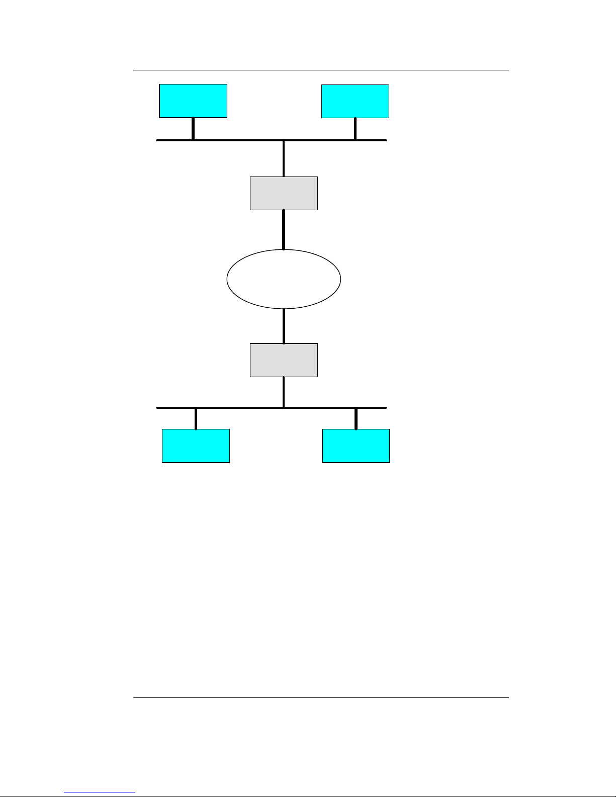
1.2.1 Connecting Two CAN Networks over Ethernet
A typical application is the connection of two CAN networks via
Ethernet over a great distance. A CAN-Ethernet Gateway is present in
each CAN network. CAN messages are transferred transparently
between the CAN-Ethernet Gateways.
The firmware of the CAN-Ethernet Gateway allows for filtration of
the CAN messages to be sent on, thus only the relevant data gets
transmitted over the Ethernet.
The principle possibilities for building a network structure using
CAN-Ethernet Gateways are represented in
Figure 1.
Introduction
© SYS TEC electronic GmbH 2007 L-1032e_9 3
Figure 1: Application Example #1: Transparent Connection of two CAN
Networks using Intranet/Ethernet
Intranet
CAN-Ethernet
Gateway
CAN-Ethernet
Gateway
CAN - Bus 1
CAN - Bus 2
Ethernet
Ethernet
CAN-Devic e C CAN-Devic e D
CAN-Devic e A
CAN-Devic e B

CAN – Ethernet Gateway
4 © SYS TEC electronic GmbH 2007 L-1032e_9
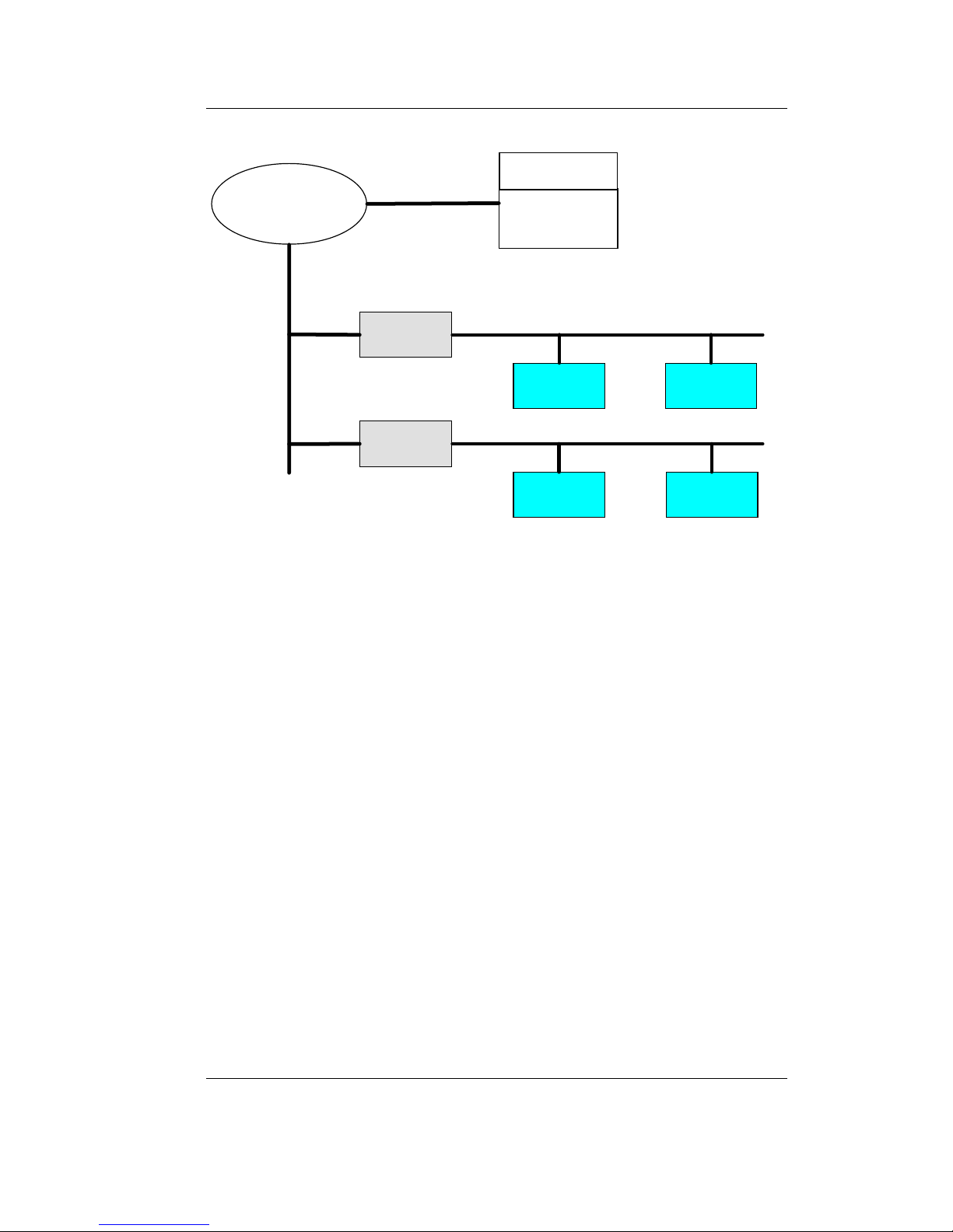
1.2.2 Remote Diagnostics and Configuration of CAN Networks
Another possible application is the connection of a CAN network with
a computer. The user only requires a network connection over the
Ethernet in order to establish a connection with the remote CAN
network. No CAN hardware is required on the host computer.
A virtual CAN-Ethernet Gateway in the form of PC software (DLL) is
available for MS Windows systems. The interface of the virtual CANEthernet Gateway corresponds to a CAN driver.
Thus it is possible to use standard CAN programs, which use a CAN
driver (e.g. CANopen configuration tools like CANsetter
TM
and
ProCANopen
TM
or CAN analyzer tools like PCAN-ExplorerTM or
PCANview
TM
).
The virtual CAN-Ethernet Gateway for PC extends the CAN network
over the Ethernet/Intranet/Internet into the office and offers new
possibilities for configuration and diagnosis of CAN networks in the
field level. The computer in the communication management level
requires an Ethernet connection to the field level, however it offers the
convenience of familiar CAN and CANopen tools.
The functions and parameters of the Gateway itself can be accessed
and modified remotely using the Telnet protocol.
Introduction
© SYS TEC electronic GmbH 2007 L-1032e_9 5
Figure 2: Application Example #2: Remote Diagnostics of CAN Networks on a
Service Computer over the Internet
1.3 Delivery Contents
The following parts are included in the CAN-Ethernet Gateway’s
delivery contents:
• GW-003 CAN-Ethernet Gateway (1* CAN) in housing for DIN
rail assembly, including a 2-pin and a 5-pin removable screw
clamp connector
• L-1032 User's Manual (this manual is on CD-ROM)
• CD-ROM with installation program for PCANview (SO-1010),
documentation, example configuration files (SO-1027)
• WK041 null-modem cable for configuration of the CAN-
Ethernet Gateway via RS-232
in preparation:
• GW-003-2 CAN-Ethernet Gateway (2* CAN) in housing for DIN
rail assembly, including a 2-pin and a 5-pin removable screw
clamp connector
Intranet
or Internet
virtual Gateway
CAN to Eth e rnet
Service PC
CAN-Ethernet
Gateway
CAN-Ethernet
Gateway
Ethernet
Ethernet
CAN - Bus 1
CAN - Bus 2
CAN-Device C CAN-Device D
CAN-Device A CAN-Device B

CAN – Ethernet Gateway
6 © SYS TEC electronic GmbH 2007 L-1032e_9

Technical Data
© SYS TEC electronic GmbH 2007 L-1032e_9 7
2 Technical Data
The CAN-Ethernet Gateway has the following technical features and
functions:
• Monitors and controls remote CAN networks over the Internet
• Couples two CAN networks
• Gateway configurable via Telnet (remote maintenance) or RS-232
• based on internal file system for configuration data
• capability of executing scripts (e.g. upon start up of the Gateway)
• flexible configuration through implementation of multiple
interfaces (refer to section
4.2)
• multiple filter mechanisms for CAN messages with the possibility
of prioritization
• Generation of a time stamp for CAN messages
• connection to Windows application programs for CAN and
CANopen
• 7 LEDs for visualization of the Gateway's state
• generation of CAN error messages
• high data throughput
• 10Base-T interface (10 Mbit/s) with RJ45 socket, galvanic isolated
• CAN interface according to CiA
1
DS102, up to 1 Mbit/s, high-
speed CAN according to ISO11898-1/2, galvanic isolated
• CAN bus connection, D-Sub-9 plug and 5-pin removable screw
clamp connector according to CiA DS102 or DeviceNet standard
• Supports CAN specification 2.0A (11-bit CAN identifier) and 2.0B
(29-bit CAN identifier)
• RS-232 interface via D-Sub-9, hardware flow control
• Supply voltage 24 VDC +20% -60%, reversed polarity protection
• Current draw approximately 90 mA
• Power connector, 2-position removable screw clamp connector
• Dimensions without connectors, 70 x 100 x 61 (L x B x H) mm³,
suitable for DIN/EN rail assembly
• Protection level: IP20
1
CiA, CAN in Automation, international users and manufacturers group
CAN – Ethernet Gateway
8 © SYS TEC electronic GmbH 2007 L-1032e_9
• Operational temperature range 0°C to +70°C
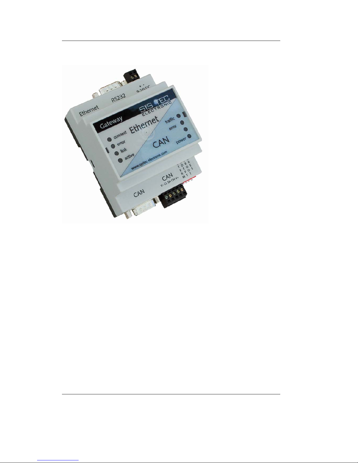
Figure 3: View of the CAN-Ethernet Gateway

Getting Started
© SYS TEC electronic GmbH 2007 L-1032e_9 9
3 Getting Started
3.1 Power Supply
A direct current voltage of 24 V –60% to +20% is required to operate
the device. The current draw of the device amounts to approximately
90 mA. The supply voltage is connected over a 2-pin, removable
screw clamp connector. Labels for the "+" and "–" polarity are printed
on the device's connector. Correct connection of the supply voltage is
indicated with the green "power" LED.
3.2 Network Connection
3.2.1 Connecting to a CAN Bus
A D-Sub-9 plug is provided for connection of the device to a CAN
network. Alternatively a connection via the 5-pin removable screw
clamp connector is also possible (suitable connector Weidmueller
‘Omnimate Range – raster 3,5mm’). This connector is wired parallel
to the D-Sub-9 plug. Its configuration corresponds to the DeviceNet
and CANopen standard.
The supply voltage for the CAN bus (pin 9 at D-Sub-9 or pin 5 at 5pin socket connector) is not connected in the Gateway. The CAN
shield potential is only connected between the two CAN connectors.
The CAN bus is galvanic isolated (optically isolated) from the
Gateway's internal circuitry.
CAN – Ethernet Gateway
10 © SYS TEC electronic GmbH 2007 L-1032e_9
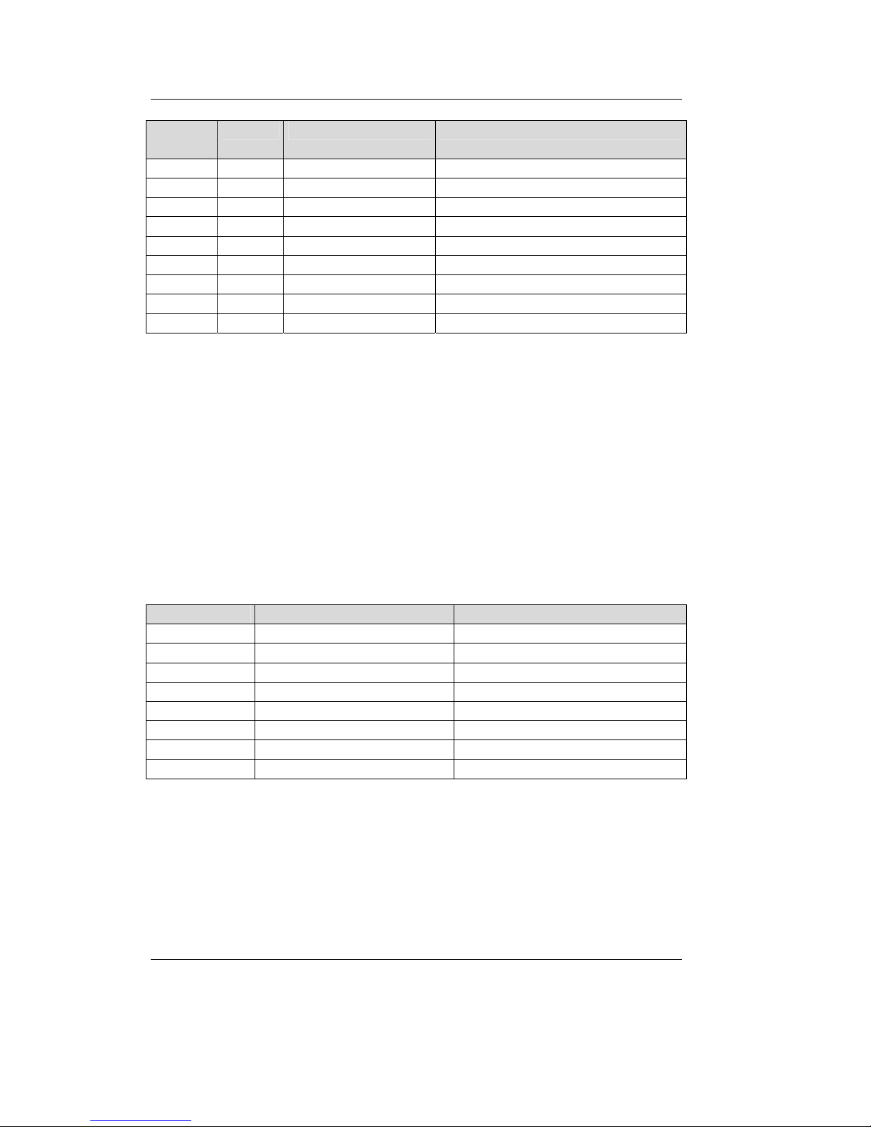
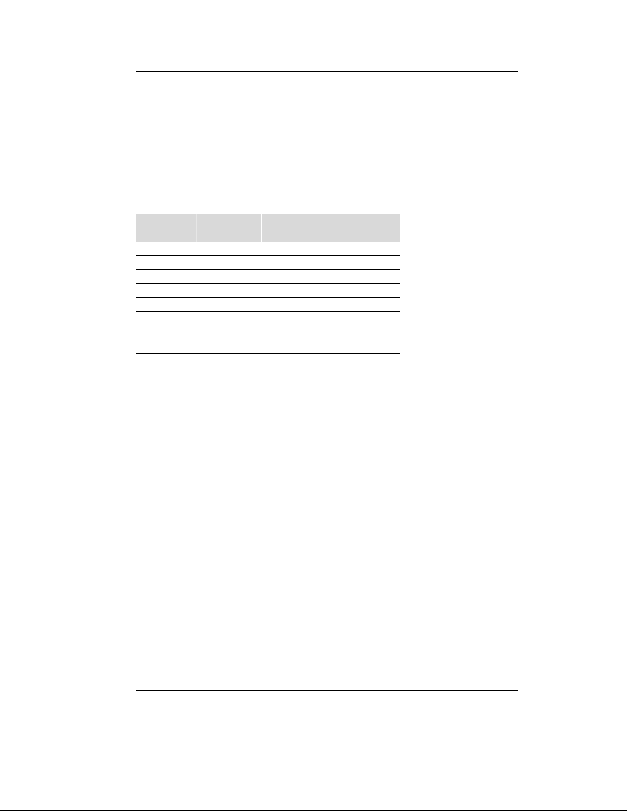
D-Sub-9
Plug
5-pol. Signal Name Description
1 n.c. not connected
2 2 CL (CAN_L) CAN_L bus line
3 1 V- (CAN_GND) CAN Ground
4 n.c. not connected
5 3 SH (CAN_SHLD) CAN Shield
6 GND CAN Ground (optional)
7 4 CH (CAN_H) CAN_H bus line
8 n.c.
9 5 V+ (CAN_V+) not connected
Table 1: CAN Connector Pin Assignment
3.2.2 Ethernet Connection
The Ethernet (10Base-T) signals are routed to an RJ45 socket for easy
connection using a standard CAT 3 or CAT 5 network cable. For
direct connection (without a hub or switch) of a CAN-Ethernet
Gateway and a PC, a crosslink cable is required.
The Ethernet connection is galvanic isolated from the CAN-Ethernet
Gateway
Pin Name Description
1 TX+ Transmit Data +
2 TX- Transmit Data 3 RX+ Receive Data +
4 n.c. not connected
5 n.c. not connected
6 RX- Receive Data +
7 n.c. not connected
8 n.c. not connected
Table 2: Ethernet Connector Pin Assignment
Getting Started
© SYS TEC electronic GmbH 2007 L-1032e_9 11
3.2.3 RS-232 Interface
The CAN-Ethernet Gateway provides an RS-232 interface with
hardware flow control. This interface is connected to a D-Sub-9 plug.
This interface allows for configuration of the CAN-Ethernet Gateway.
This connector is specifically intended for initial configuration (refer
to section
3.5). The RS-232 interface is not galvanically separated.
DB-9 Plug,
Pin#
Name Signal Description
1 CD Carrier Detect
2 RXD Receive Data
3 TXD Transmit Data
4 DTR Data Terminal Ready
5 GND System Ground
6 DSR Data Set Ready
7 RTS Request to Send
8 CTS Clear to Send
9 RIN Ring Indicator
Table 3: RS-232 Interface Connector Pin Assignment
The CAN-Ethernet Gateway is connected to the PC via a null modem
cable.

CAN – Ethernet Gateway
12 © SYS TEC electronic GmbH 2007 L-1032e_9
3.3 Device Status Display
There are a total of 7 LEDs (refer to Table 4) for displaying the
operational state of the device. The displays are arranged according to
their meaning to the networks (refer to
Figure 3). One red and one
green LED show the state of the CAN or Ethernet network. Detailed
description of the "error" LEDs can be found in section
6.1.
LED Name Description
power Supply Voltage OK [green]
connect A connection to the other Gateway is established over
UDP or TCP [green]
error (Ethernet) Error during data transfer on the Ethernet connection
(refer to section 6.1) [red]
link Connection to Ethernet established, cabling OK [green]
active Data transfer over Ethernet [yellow]
traffic Indicates data traffic on the CAN bus [green]
error (CAN) Error during data transfer on the CAN connection (refer
to section 6.1) [red]
Table 4: Meaning of the Device Status LEDs
Getting Started
© SYS TEC electronic GmbH 2007 L-1032e_9 13
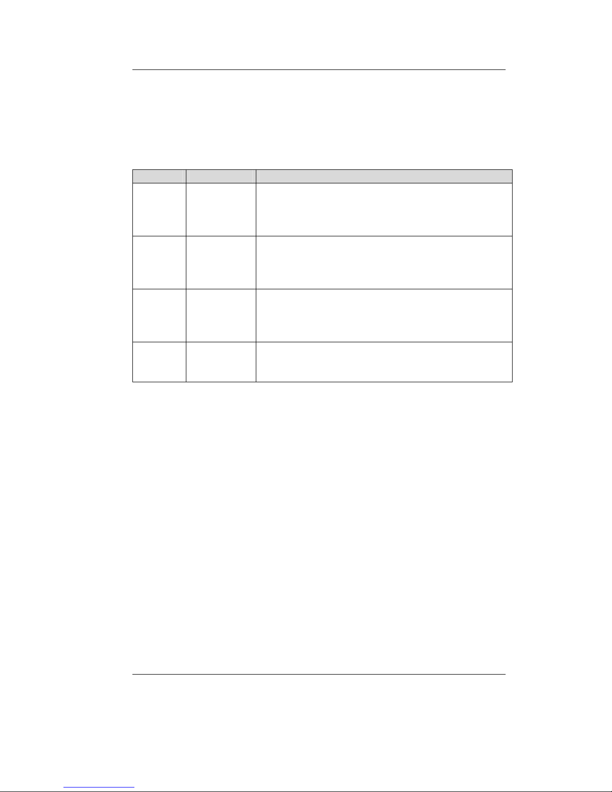
3.4 Switches
Four DIP-switches are available on the CAN-Ethernet Gateway for
configuration purposes of the device. Their function is described in the
following table:
Switch # Name Description
1 TERM Defines whether the CAN terminating resistor of
120 Ohm is active or not
ON Æ terminating resistor active/enabled
OFFÆ terminating resistor not active/disabled
2 DEFT Defines the start initialization of the CAN-Ethernet
Gateway (refer to section 3.5)
ON Æ factory default configuration will be loaded
OFFÆ user configuration will be loaded
3 BOOT Activate the “Bootstrap-Mode” of the CAN-Ethernet
Gateway (refer to section 8)
ON Æ “Bootstrap-Mode” will be entered
OFFÆ Firmware of the CAN-Ethernet Gateway starts
4 RES Reset the CAN-Ethernet Gateway (refer to section 8)
ON Æ Reset active/enabled
OFFÆ Reset not active/disabled
Table 5: Meaning of the Switches

CAN – Ethernet Gateway
14 © SYS TEC electronic GmbH 2007 L-1032e_9
3.5 Initial Setup and Operation
3.5.1 Standard Configuration
The CAN-Ethernet Gateway has the following standard (factory
default) configuration (Setting the Configuration Script, refer to
section
5.1):
Ethernet/Internet settings
IP address of the CAN-Ethernet Gateway: 192.168.10.111
Subnet- Mask: 255.255.255.0
Standard Gateway: 192.168.10.1
one UDP
2
server
one TCP server
CAN settings
CAN bit rate: 1 Mbit/s
CAN identifier for error messages: 0xFE
RS-232 interface
Baud rate: 9600 baud
Data bits: 8
Parity: none
Stop bits: 1
Protocol/flow control: hardware
2
BTP: Block Transfer Protocol for transmitting CAN messages via UDP/IP
Getting Started
© SYS TEC electronic GmbH 2007 L-1032e_9 15
3.5.2 Initial Configuration using the RS-232 Interface
The CAN-Ethernet Gateway must be configured to meet the specific
application requirements before CAN messages can be transmitted.
The following steps are required:
• Connect the included null modem cable to the RS-232 interface of
the CAN-Ethernet Gateway and a free serial interface on the PC
(e.g. COM1).
• Start a terminal program on the PC, the program "HyperTerminal"
will be used for the following examples, this program is part of the
MS-Windows operating system (if you use a different terminal
program, appropriate configuration must be made).
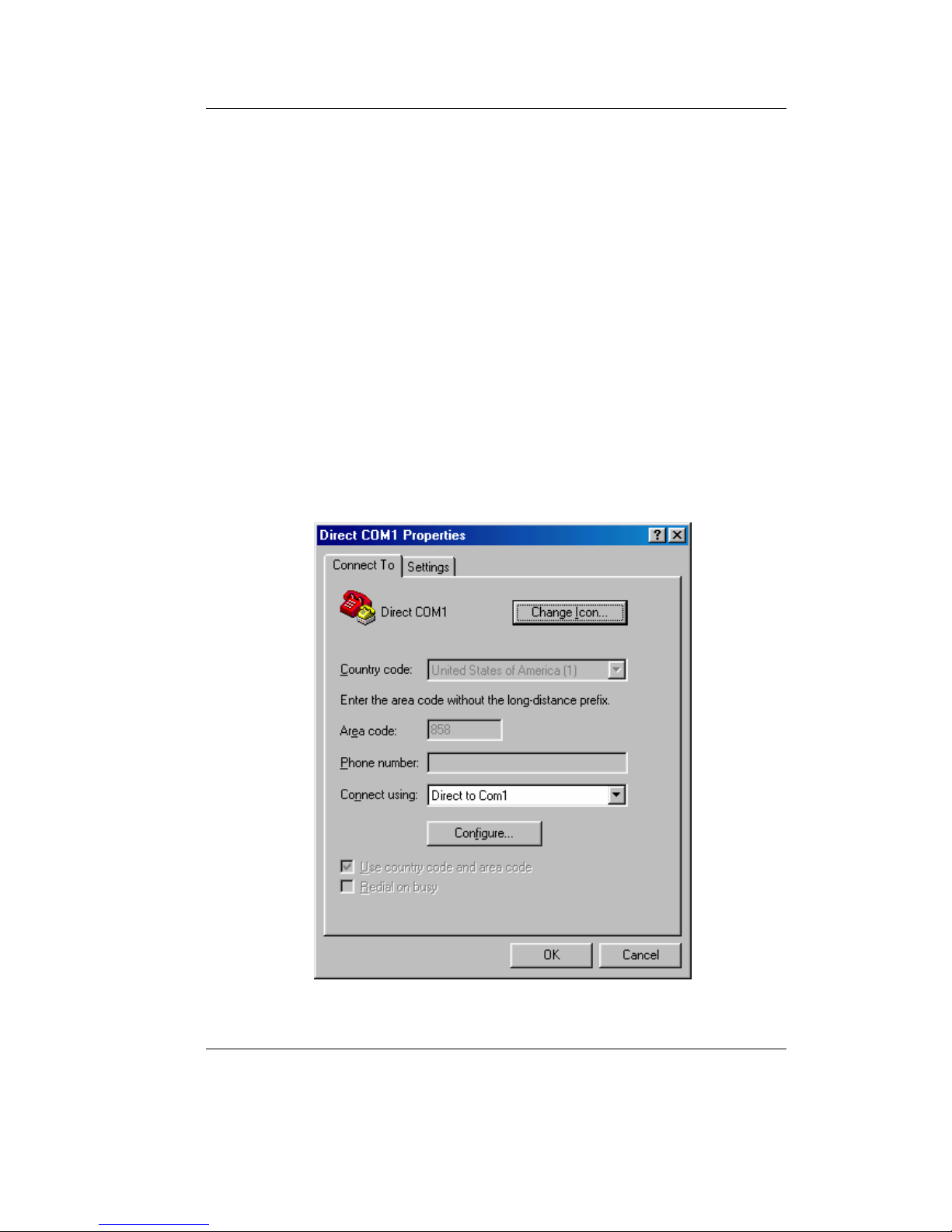
• Set the baud rate and the protocol for the serial interface (e.g.
COM1) in HyperTerminal (refer to
Figure 4 and Figure 5).
Figure 4: HyperTerminal Configuration (1)
CAN – Ethernet Gateway
16 © SYS TEC electronic GmbH 2007 L-1032e_9
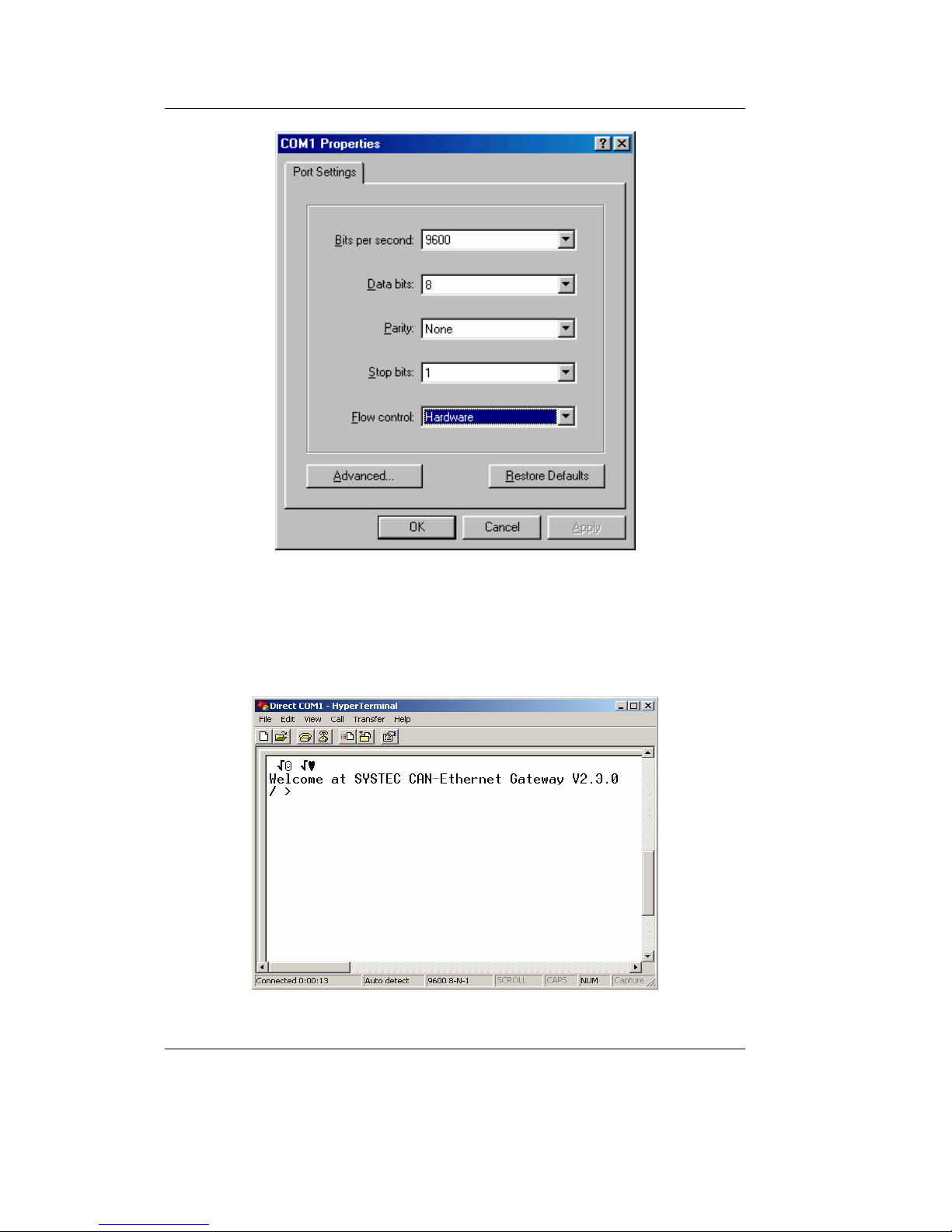
Figure 5: HyperTerminal Configuration (2)
• Be sure that you have correctly connected the supply voltage
(polarity) and then turn on the power.
Figure 6: CAN-Ethernet Gateway Start Message

Getting Started
© SYS TEC electronic GmbH 2007 L-1032e_9 17
Proper startup of the device is indicated by a (refer to Figure 6)
Welcome at SYSTEC CAN-Ethernet Gateway V2.3.0
/ >
message.
The device then waits for the input of commands. The startup message
portion "V2.3.0" represents the current version number and may vary.
Since the CAN-Ethernet Gateway is based on an internal file system,
there are commands for navigation. These commands are (refer to
section
4.5):
ls to show the contents of the current directory,
cd to switch the current directory
write to create a new file
rm to delete a directory/file
sync in order to store a file in non-volatile memory (EEPROM)
Predefined files are included for initial configuration. These are
located on the CD under
\Products\GW-003\SO-1027\RC-Files\UDP (for the UDP transfer) or
\Products\GW-003\SO-1027\RC-Files\TCP (for the TCP transfer).
Each folder contains a file for a server configuration
UDP_Server_1CAN.txt or TCP_Server_1CAN.txt and a file for a
client configuration UDP_Client_1CAN.txt or TCP_Client._1CANtxt.
• Copy these files into a folder of your choice on your PC (e.g.
C:\SYSTEC\GW-003\RC-Files). Before you transfer one of these
files to the CAN-Ethernet Gateway you must modify the file. Open
the file Udp_Server_1CAN.txt with an editor.
• Modify the local IP address, the subnet mask and the standard
Gateway address to the values that correspond to your application
requirements (refer to section
4.5.12).
for example:

CAN – Ethernet Gateway
18 © SYS TEC electronic GmbH 2007 L-1032e_9
ipcfg 192.168.10.117 255.255.255.0 192.168.10.1
• Set the CAN bitrate and the CAN identifier for error messages,
(refer to section
4.2.4)
for example: to 125 kBit/s and CAN identifier 0x81
/if/can0 baud:4 canid:81 on
• Save the configuration file under a different name,
for example
UdpServer_1CAN_117.txt
The generated configuration file is written to the CAN-Ethernet
Gateway as follows:
1. Change to the directory /save
/ >cd /save↵
/save >
2. Erase the existing configuration file rc
/save >rm rc↵
/save >sync↵
Getting Started
© SYS TEC electronic GmbH 2007 L-1032e_9 19
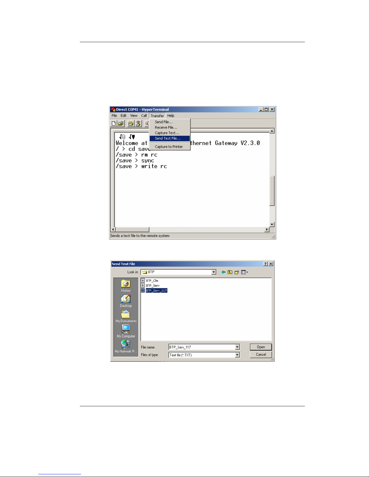
3. Write a new configuration file rc
/save >write rc↵
After you’ve input the command you can send a file to the CANEthernet Gateway using the HyperTerminal tool. The following
images show how to do this:
Figure 7: Sending a Configuration File via HyperTerminal
Figure 8: Selecting a Configuration File
CAN – Ethernet Gateway
20 © SYS TEC electronic GmbH 2007 L-1032e_9
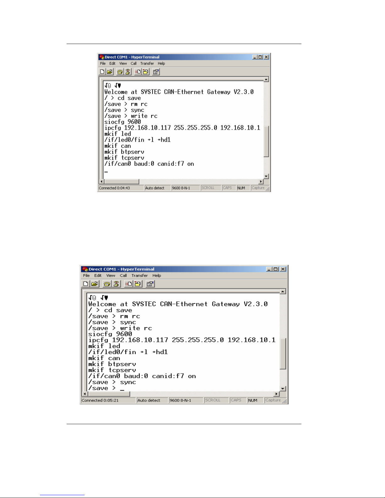
Figure 9: Successful Transmission of a Configuration File, Terminate with
Crtl+D
4. To end the transfer push Ctrl+D. The Gateway will show the
execution with the prompt
/save >
5. Save the file rc with the command sync in EEPROM.
Figure 10: Finishing the Configuration
Getting Started
© SYS TEC electronic GmbH 2007 L-1032e_9 21
6. Set the switch 2 "DEFT" to OFF and restart the CAN-Ethernet
Gateway. Upon restart of the CAN-Ethernet Gateway with poweron or via the command
reset, the saved configuration file will be
executed and the CAN-Ethernet Gateway will be configured.
/save >reset↵
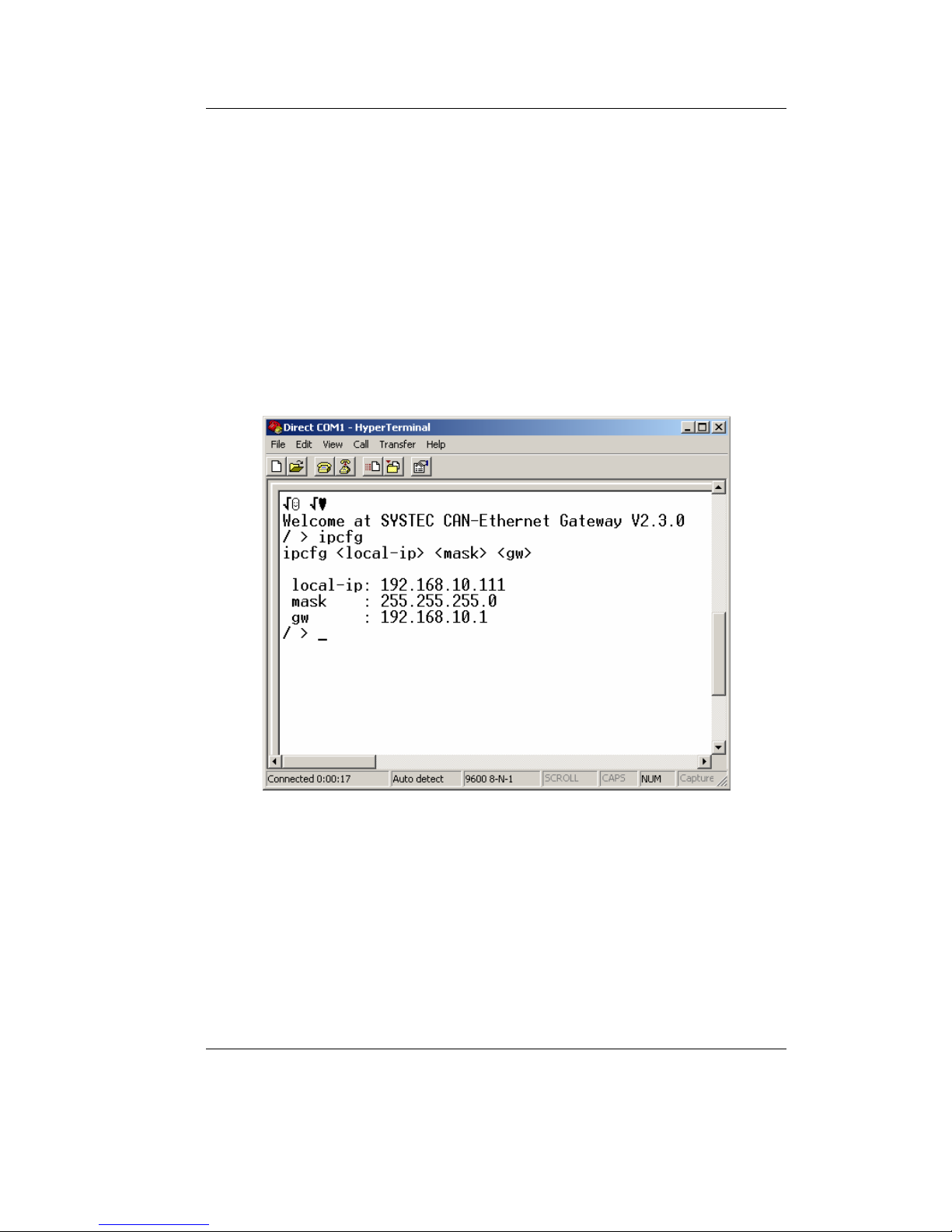
7. Verify the new configuration by inputting the command
ipcfg (see
Figure 11). The parameter IP address, subnet mask and standard
gateway stored in the configuration file all correspond to their
settings. Now the Gateway is configured and can be accessed over
the Ethernet (e.g. Telnet).
Figure 11: Verifying the Selected Configuration
This concludes the initial start up of the device.
The CAN-Ethernet Gateway functions with different interfaces (refer
to section
4.2), which enable the data exchange over the Ethernet and
CAN. Interfaces are created with the command
mkif and deleted with
the command
rm. All created interfaces appear in the folder /if. An
interface can be addressed and configured via a direct call to the
directory (refer to section
4.2.4).

CAN – Ethernet Gateway
22 © SYS TEC electronic GmbH 2007 L-1032e_9
3.5.3 Configuration and Operation using Telnet
Configuration of the CAN-Ethernet Gateway during operation is also
possible via Telnet (TCP port 23). The function parameters are the
same as those of the RS-232 interface. Use of Telnet also enables
configuration of remote CAN-Ethernet Gateways. A condition for this,
however, is the initial configuration of the IP address with the
command
ipcfg (refer to section 4.5.12). Without this initial
configuration of the IP address the CAN-Ethernet Gateway can only
be addressed via its standard configuration (refer to section
3.5.1).
A Telnet client is already included in the Windows package. This
Telnet client can be called via
telnet <Address>. Under Linux the
programs
telnet or netcat can be used.
 Loading...