

Page 1
deltawaveC-F/P
Manual
1 systec Controls Mess- und Regeltechnik GmbH
Manual
deltawaveC-F/P
Ultrasonic flow and heat measurement
portable
Stationary
Ver. 1.43.xx
Page 2

deltawaveC-F/P
Manual
2 systec Controls Mess- und Regeltechnik GmbH
Table of content
Table of content ........................................................................................................ 2
1 Preamble ........................................................................................................... 5
2 About this manual .............................................................................................. 6
3 deltawaveC-F/P & components ......................................................................... 7
3.1 Approvals / EMC .................................................................................... 7
3.2 Scope of delivery deltawaveC-F / P basic package ............................... 8
3.3 Transducer............................................................................................. 9
3.4 Safety instructions ............................................................................... 10
3.5 Important instructions for the use of deltawaveC-P ............................. 10
4 Measuring principle.......................................................................................... 11
4.1 2-channel device applications .............................................................. 13
5 deltawaveC-F/P Interfaces .............................................................................. 14
5.1 Overview deltawaveC-P ...................................................................... 14
5.2 Overview deltawaveC-F ....................................................................... 15
5.3 Connection notes ................................................................................. 16
6 Operating ......................................................................................................... 17
6.1 Control Buttons .................................................................................... 17
6.2 How to navigate ................................................................ ................... 17
6.3 Select measurement channel .............................................................. 17
7 First Start ......................................................................................................... 18
7.1.1 Adjustment of the display language ................................................ 18
7.1.2 Navigation in main menu ................................................................ 19
7.1.3 Setting time and date ...................................................................... 20
8 Preparing for measurement deltawaveC-F/P ................................................... 21
8.1 Preparation of the measurement / installation location ........................ 21
8.1.1 Inlet and outlet distances ................................................................ 21
8.1.2 Basic principles for ultrasonic transducer assembly ........................ 23
8.1.3 Ultrasonic sensor Mounting on horizontal pipelines ........................ 23
8.1.4 Ultrasonic transducer on uneven surfaces ...................................... 24
8.2 Fundamentals of parameterization ...................................................... 25
8.3 Parameterization with the Quick Setup ................................................ 26
8.4 Sensor assembly / Sensor distance ..................................................... 33
8.4.1 Introduction to the installation of ultrasonic transducers ................. 33
8.4.2 Mounting ultrasonic transducer ....................................................... 34
8.4.3 Correct selection of transducer types .............................................. 35
8.4.4 Correct selection of mounting options ............................................. 35
8.4.5 Mounting of the Transducer in V-Mode or W-Mode ....................... 36
8.4.6 Mounting the ultrasonic transducers based on the Z method ......... 38
8.4.7 Mounting the ultrasonic transducers at two crossed measuring paths
40
8.5 Zero Setting ......................................................................................... 41
9 Heat measurement .......................................................................................... 42
Page 3

deltawaveC-F/P
Manual
3 systec Controls Mess- und Regeltechnik GmbH
9.1 Introduction .......................................................................................... 43
9.2 Installing the Pt100 .............................................................................. 44
9.3 Parameterization of the Pt100 for the heat quantity measurement ...... 45
10 Measuring windows deltawaveC-F/P ........................................................ 46
10.1 Headline .............................................................................................. 46
10.2 Measuring window "Flow 1" ................................................................. 47
10.3 Measuring window "Flow 2" ................................................................. 48
10.4 The measuring window "heat quantity" ................................................ 49
10.5 Password protection ............................................................................ 50
10.6 The measurement windows of the 2-channel deltawaveC-F ............... 51
11 The main menu (complete menu) ............................................................. 52
11.1 Loading, saving and managing parameter data ................................... 52
11.2 The pipe parameters ............................................................................ 54
11.3 The Fluid Setup ................................................................................... 55
11.4 The Transducer Setup ......................................................................... 56
11.5 Parameterization of the inputs and outputs ......................................... 57
11.5.1 Parameterization of the 4-20mA outputs ......................................... 57
11.5.2 Parameterization of the relay .......................................................... 59
11.5.3 Parameterization of the pulse output .............................................. 60
11.5.4 Impulse-Overflow-Error; IOE ........................................................... 61
11.6 Serial communication, Modbus & Logger ............................................ 61
11.6.1 Serial data transmission .................................................................. 61
11.6.2 Modbus ........................................................................................... 63
11.6.3 The Data Logger ............................................................................. 64
11.6.3.1 Activation of the data logger function:.................................... 64
11.6.3.2 Administration and structure of log data ................................ 65
11.6.3.3 Starting a time-controlled data record.................................... 65
11.6.3.4 Cancelling a time-controlled data record ............................... 67
11.6.3.5 Quick-Logger ......................................................................... 67
11.7 Systems Settings ................................................................................. 68
11.7.1 Editing the time and date ................................................................ 68
11.7.2 Changing the indicator light............................................................. 68
11.7.3 Changing the menu language ......................................................... 69
11.7.4 System test ..................................................................................... 69
11.7.5 System information ......................................................................... 70
11.7.6 System Reset .................................................................................. 70
11.8 Unit selection ....................................................................................... 71
11.9 Calibration ........................................................................................... 72
11.9.1 Flow-Offset ...................................................................................... 72
11.9.2 Matching the Pt100 ......................................................................... 72
11.9.3 Pt100 Offset .................................................................................... 72
11.9.4 Calibration of analogue outputs ...................................................... 73
11.9.5 Parameterization of a flow velocity characteristic ............................ 73
11.10 Miscellaneous Parameters .................................................................. 75
11.10.1 Damping & Burnout ......................................................................... 75
11.10.2 Cut off Flow ..................................................................................... 76
Page 4

deltawaveC-F/P
Manual
4 systec Controls Mess- und Regeltechnik GmbH
11.10.3 Zero ................................................................................................ 76
11.10.4 The totalizer (counters) ................................................................... 76
11.10.5 Sensor distance ................................ .............................................. 78
12 Additional information about the hardware ............................................... 79
12.1 Hardware and Software Reset ............................................................. 79
12.2 Data export and import ........................................................................ 80
12.3 Parameterization of the deltawaveC-F pulse output hardware ............ 81
12.3.1 Operating mode 1: High Side (PNP-Switch) ................................... 82
12.3.2 Operating mode 2: LOW Side (NPN-Switch) ................................. 83
12.3.3 Operation Mode Push-Pull .............................................................. 84
12.4 RS232 / RS485 Interfaces ................................................................... 85
13 Tips and Tricks ......................................................................................... 87
13.1 Measuring unknown fluids ................................................................... 88
14 Troubleshooting ........................................................................................ 90
14.1 The Oscilloscope Window ................................................................... 91
14.2 Signal analysis ..................................................................................... 92
14.2.1 Signal-to-noise ratio (SNR) ............................................................. 93
14.2.2 Signal sharpness ............................................................................ 95
14.2.3 Signal decoupling on small pipelines .............................................. 96
14.2.4 The Auto window function / AFC-Technology ................................. 97
14.3 The diagnose window of the deltawaveC-F/P ...................................... 99
14.4 Integrated sensor test function........................................................... 100
14.5 What to do if the pipe is not fully filled? .............................................. 101
14.6 Checklist ............................................................................................ 102
Appendix A – Material data ................................ ................................................... 105
Appendix B – Technical data ................................................................................ 108
Appendix C – Modbus register overview .............................................................. 110
Appendix D – Transducer type overview .............................................................. 112
Appendix E – Mounting equipment and accessories ............................................ 114
Page 5

deltawaveC-F/P
Manual
5 systec Controls Mess- und Regeltechnik GmbH
1 Preamble
Welcome to the team of deltawaveC-F/P users and many thanks for using
an ultrasonic clamp-on flowmeter from systec Controls GmbH Germany.
deltawaveC-F/P was developed based on the KISS principle – “keep it safe
and simple”.
That means maximum user friendliness paired with optimal and accurate
measurements.
Our aim is to fulfil these aspirations both now and in the future. Our
strength lies in continually improving and optimising our products and we
want you to be part of this.
deltawaveC-F/P is an important product for us and not just one product on
a long list of others.
Thanks to your competent and constructive suggestions you have helped
to co-create deltawaveC and contribute to its success.
Please don´t hesitate to share your expert knowledge about deltawaveCF/P with us.
We wish you all the best and great success with using deltawaveCF/P!
Page 6
deltawaveC-F/P
Manual
6 systec Controls Mess- und Regeltechnik GmbH
2 About this manual
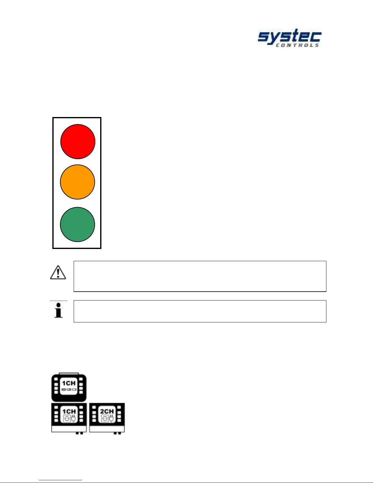
You don't have much time for reading? Use the beacon!
Next to the chapters you will find red, orange or green dots. They will help
you to find a quick introduction to the deltawaveC-F/P
Newcomer?
You have never worked with an ultrasonic meter before?
Start at the first chapter. You will receive a step-by-step introduction to
ultrasonic measuring technology.
Advanced?
You have occasionally used ultrasonic measuring equipment?
Start with chapter 10.1.3 "Quick setup"
Start with the chapters that are marked with an orange spot. You may also
want to continue reading the chapters with the green spot.
Professional?
You already have professional knowledge of ultrasonic measuring
systems?
Start with the deltawaveC-F Getting Started (separate attachment)
You may also want to read the green dot chapters
The fields identified with an exclamation mark contain important
information that relates to the basic data and operation of the
device.
The fields identified with the “i“ contain supplementary and helpful
information.
The instruction manual describes the function of both deltawaveC-P and
deltawaveC-F in 1-channel and 2-channel version. In addition to the chapters
you will find the corresponding pictograms. This indicates which of the
devices the chapter applies to.
deltawaveC-P
portable deltawaveC (1 Channel)
deltawaveC-F
stationary deltawaveC
1CH = 1 Channel; 2CH = 2 Channel
Page 7
deltawaveC-F/P
Manual
7 systec Controls Mess- und Regeltechnik GmbH
3 deltawaveC-F/P & components
deltawaveC-F/P key points:
deltawaveC-F/P is a clamp-on ultrasonic flow meter for liquids in
completely filled pipelines.
deltawaveC-F/P works based on the transit time method.
deltawaveC-F/P provides heat measurement by default. Clamp-on Pt100
temperature sensors are available as an optional.
The power is supplied via integrated AC-power supply. For deltawaveC-F
DC-power supply is available.
The device supports measurements on pipelines with diameters in the
range DN10 to DN6000 (depending on the sensor used)
Temperature range (fluid): –40°C to +150°C (equates the temperature
range of the clamp-on ultrasound transducers)
deltawaveC-F/P is equipped with an electrically isolated relay output, as
well as 4 to 20 mA current and impulse outputs that can be operated in
active and passive mode.
The stationary deltawaveC-F can optionally be equipped with an RS232 or
RS485 interface card as well as with two additional analogue inputs.
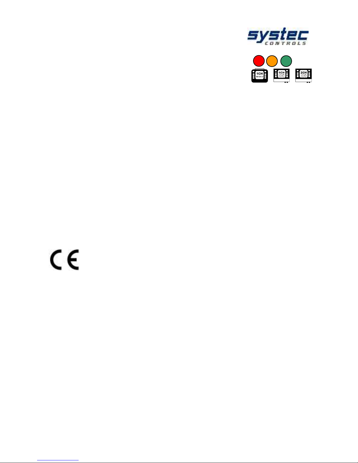
3.1 Approvals / EMC
deltawaveC-F/P is compliant with the following European
Directives and Standards:
2014/35/EU Low voltage directive
2014/30/EU Electromagnetic compatibility
Inspection specifications:
EN 55011 (2011-04)
EN 61000-4-2 (2009-12)
EN 61000-4-3 (2011-04)
EN 61000-4-4 (2013-04)
EN 61000-4-5 (2015-03)
EN 61000-4-6 (2014-08)
EN 61000-4-8 (2010-11)
EN 61000-4-11 (2005-02)
Inspection requests:
EN 61000-6-1 (2016-05)
EN 61000-6-3 (2011-09)
Page 8
deltawaveC-F/P
Manual
8 systec Controls Mess- und Regeltechnik GmbH
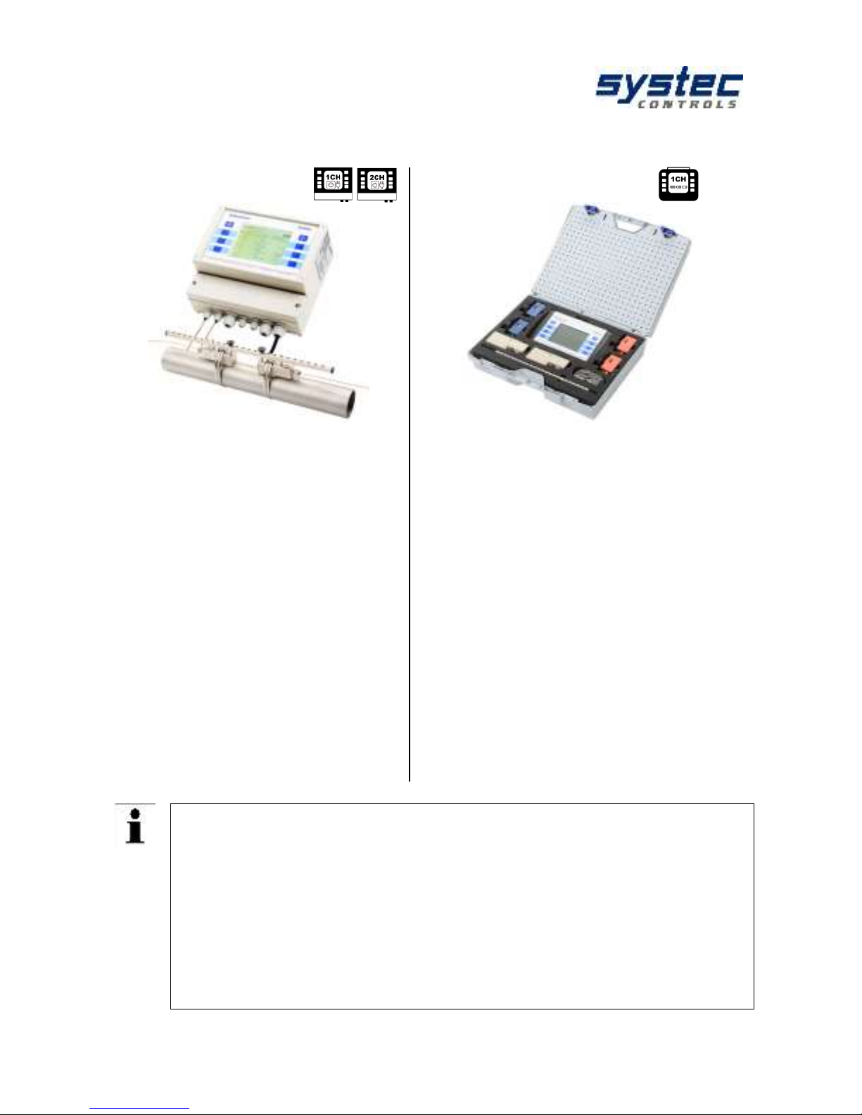
3.2 Scope of delivery deltawaveC-F / P basic package
deltawaveC-F
deltawaveC-P
deltawaveC-F & ultrasonic transducers
deltawaveC-P hard-shell case
deltawaveC-F flow transmitter
Ultrasonic transducers incl.
signal cables (cable length
according to order)
Spacer bar for transducers,
except for FW05
Mounting belt – stainless steel
Quick start Guide
CD with manual
Acoustic coupling pads
Hard-shell case
deltawaveC-P flow transmitter
Plug-in power adapter, including
an IEC appliance power cable
RG 58 connector cable for
transducer
Ultrasonic transducer (as
ordered by the customer)
Mounting material and spacer
bar for transducers
Cable for 4mA to 20mA analogue
output (Mini DIN, alligator clips)
Quick start Guide
CD with Manual
Ultrasonic coupling grease
Other ultrasonic transducers for smaller or larger pipe dimensions, as well
as clamp-on temperature sensors, are available on separate order.
Every deltawaveC-F can be retrofitted with a serial interface board
(optional). It can be connected either to an RS232 serial interface board or
to a RS485 interface.
You can reach your personal contact partner on the Internet at
www.systec-controls.de, or at the phone number +49 (0)89 80 90 60.
An overview of accessories and available transducer can be found in the
appendix.
Page 9

deltawaveC-F/P
Manual
9 systec Controls Mess- und Regeltechnik GmbH
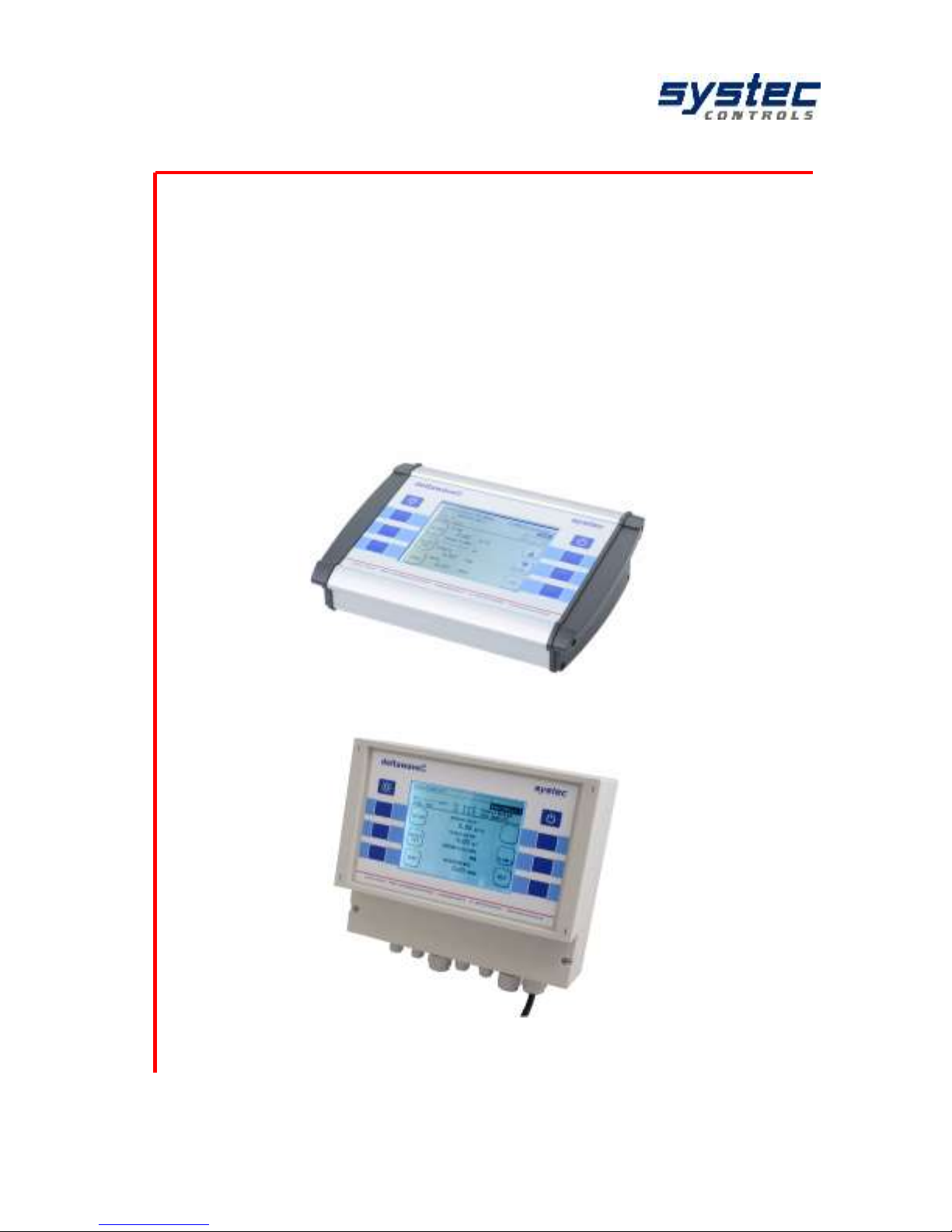
3.3 Transducer
Figure 1: deltawaveC-F/P – measuring converter and mounted ultrasound transducer;
left: deltawaveC-F, right: deltawaveC-P
Your deltawaveC-F / P essentially consist of the ultrasonic transducers mounted on
your pipeline and the transmitter. The transmitter performs the signal processing
and provides the user with the measurement results. The ultrasonic transducers
transform the electrical energy into kinetic energy (acoustic wave). The ultrasonic
transducer can also receive acoustic waves and convert these into electrical
energy. An overview of the available converters can be found in the appendix.
The ultrasonic transducers will be mounted on the pipeline, they generate and
receive the ultrasonic signals, by means of which flow rate will calculated in the
transmitter.
As a result of the measuring principle, each transmitter is equipped with a
pair of ultrasonic transducers (A & B). Make sure ultrasonic transducers are
aligned with the direction of flow. Pay attention with the deltawaveC-F
(screw terminals), the loop has to be at the correct position and correct
polarity:
( + ) = red cable (core)
( – ) = black cable (shield)
UP-Transducer (upstream positioned transducer):
The ultrasound transducer, which the flow passes first, is connected at the UPcontacts.
DOWN-Transducer (downstream positioned transducer):
The ultrasound transducer, which the flow passes second, is connected at the
DOWN-contacts.
Page 10

deltawaveC-F/P
Manual
10 systec Controls Mess- und Regeltechnik GmbH
3.4 Safety instructions
The operating temperature of the transmitter from -20°C to 60°C must
not be exceeded!
The ultrasonic sensors are sensitive to strong mechanical impacts
(irreparable damage possible)!
The transmitter and ultrasound transducers are generally not approved
for operation in potentially explosive atmospheres (request documents
for ATEX equipment).
The ultrasonic sensors must not exceed the specified operating
temperatures.
3.5 Important instructions for the use of
deltawaveC-P
The plug-in power supply is only suitable for indoor use! In the case of mechanical
or electrical damage to the plug-in power supply unit or the 230V power supply
cable, these must be completely replaced!
DeltawaveC-P is equipped with a nickel metal hydride battery (NiMH, 2300mAh).
This battery power is sufficient for approximately 5 hours of network-independent
operation.
To increase the battery life time, we recommend the following:
Charge and discharge the battery 3 times completely as soon as you have received
your deltawaveC-P.
If the deltawaveC-P is not used for a long time, recharge the battery at
least once every 3 ... 6 months.
The deltawaveC-P is equipped with a deep discharge protection. A pop-up
message informs you before the device switches off automatically.
To avoid unnecessary stress to the battery avoid connecting the
deltawaveC-P to a power supply if it is already charged completely.
deltawaveC-P is equipped with a quick-charge function. The quick-charge
function is automatically activated for 20 minutes after deltawaveC-P is
connected to the power supply. This allows for quick instant operation of
the device.
General information about the charge states:
Charging
50-100%
25-49%
10-25%
<10%
Page 11
deltawaveC-F/P
Manual
11 systec Controls Mess- und Regeltechnik GmbH
The exclamation point in the battery indicator appears if the charge is too
low, or if deltawaveC-P is busy determining the current charge status.
Determining the charge level might take up to one minute.
If the exclamation mark persists, the battery actually has a capacity <10%.
If "Err" appears in front of the battery symbol and "x" in the battery symbol,
this means that the battery is defective or there is a fault in the charging
circuit. If you restart deltawaveC-P three times and the error message
persists, please contact systec Controls.
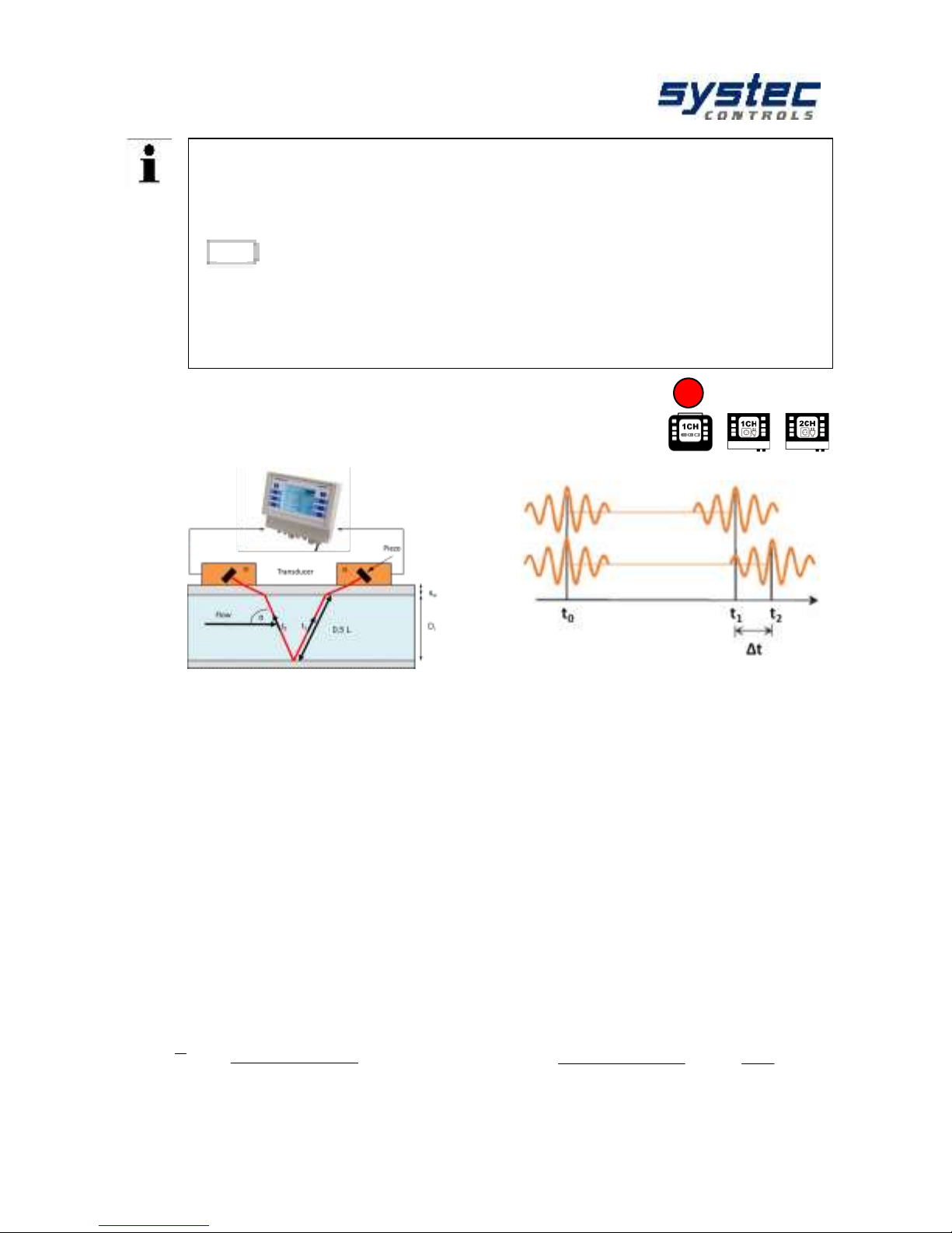
4 Measuring principle
Measuring principle: Ultrasonic transit time difference method (Clamp-On)
For this purpose two ultrasonic transducers are mounted on the pipeline from
outside and connected to the evaluation electronics.
The ultrasonic transducers work alternately as transmitters and receivers and send
ultrasonic signals at each other. These signals are accelerated or decelerated by
the medium flow. The resulting difference in the two signal propagation times is
proportional to the flow rate and is used together with the pipeline geometry for the
precise calculation of the flow rate.
Signal evaluation by means of cross-correlation:
The signal processing operates on the basis of a cross-correlation-based method,
which enables signal detection even at a low signal-to-noise ratio. On the basis of
the high-quality signal evaluation, measurements with gas input or solid load of the
medium are also possible within certain limits.
Calculation of the flow velocity [m/s]:
Calculation of the volume flow:
x
4cos2
)(
2
Re
12
D
k
tt
t
LQ
Re
12
cos2
)(
k
tt
t
Lv
Page 12

deltawaveC-F/P
Manual
12 systec Controls Mess- und Regeltechnik GmbH
Integrated Reynolds-compensation (kRe):
The transit time difference method provides to determine the mean flow velocity
along the measuring path. The mean flow velocity over the tube cross-section can
be determined by means of a compensation factor which is dependent on the
Reynolds number.
The Reynolds number is determined iteratively from the current flow rate, the pipe
diameter and the kinematic viscosity of the fluid. For fluids of the device-internal
material database the data is provided.
The configuration of a user-defined medium is possible. For this purpose, the sound
velocity (can be practically determined by iterative approximation, see 13.2) and the
kinematic viscosity of the medium must be parameterized. The input of density and
heat capacity is additionally required for determining the heat quantity.
Re… Reynolds number,
v… flow velocity,
D… diameter,
ρ… density,
µ… dynamic viscosity,
υ… kinematic viscosity,
Integrated temperature compensation / Automatic Fluid Control (AFC):
Changes to the sound velocity of the liquid (temperature-dependent or when the
medium changes) cause changes of signal path angles and path length. These
deviations from the ideal path and the resulting measurement uncertainties are
compensated automatically by a correction factor (qp factor) determined by
deltawaveC-F / P without mechanical displacement of the transducers.
Standard:
The basis for the calculation is the VDI/VDE directive 2642: "ULTRASONIC FOWRATE MEASUREMENT OF FLUIDS IN PIPES UNDER CAPACITY FLOW
CONDITIONS" (12/1996)
DvDv
Re
Page 13

deltawaveC-F/P
Manual
13 systec Controls Mess- und Regeltechnik GmbH
4.1 2-channel device applications
The deltawaveC-F 2-channel transmitter enables the realization of exceptional
measurement requirements for special applications. These are briefly described
below.
Two measuring paths can be operated separately at two different measuring points.
In addition to the separate results of measuring points (CH1 or CH2), the sum, the
difference as well as the mean value of both measuring paths are provided
additionally (CH1 + CH2, CH1 - CH2, (CH1 + CH2) / 2).
The mean value calculation is intended in particular for the use of both measuring
paths at one measuring point. This utilization makes it possible to increase the
accuracy and to reduce the effects of cross currents.
The heat quantity determination is limited to the use of two measuring
paths at one measuring point (only one pair of Pt100 can be connected).
The calculation is performed only for (CH1 + CH2) / 2.
A separate calculation only for CH1 and/or CH2 is not provided.
Page 14
deltawaveC-F/P
Manual
14 systec Controls Mess- und Regeltechnik GmbH
5 deltawaveC-F/P Interfaces
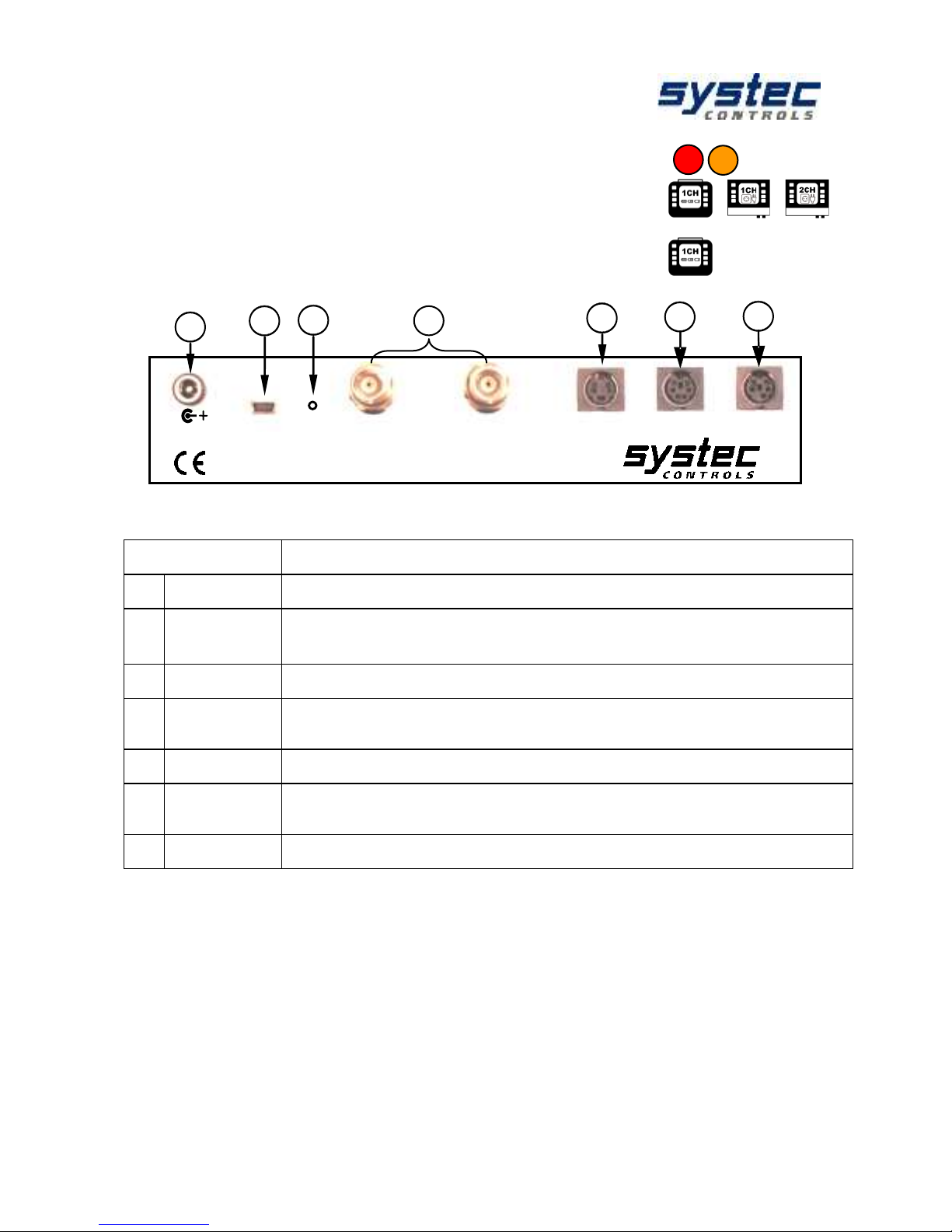
5.1 Overview deltawaveC-P
Term
Description
1
UP/ DWN
BNC-Inputs for ultrasonic transducer
2
Relays/
Impulse
Mini-DIN-4 connectors output: Relay connection (passive, potential-free);
Digital output (open collector: 20, 40, 60 ms square pulses)
3
T1/T2
Mini-DIN-6 connectors: 1 pair 3-conductor Pt100 (heat measurement):
4
Analog Out
2 Analogue outputs: 4…20mA signal, 24VDC, active (optional passive)
from CTRL 2.1 according to Namur NE43 (3.8-20.5 mA)
5
RESET
Hardware-Reset (Restart of the system)
6
USB
USB Interface (Mini-USB Type B), access to the integrated SD memory card
Windows XP or later versions detect the SD Card as mass storage medium
7
Power
Plug-in power: 19 V/DC, 3,42 A
Power
18,5 VDC
USB
Down
Up
T1/T2
Relays/Impulse
Analog Out
deltawaveC
Reset
1
4 3 5
6
7
2
Page 15
deltawaveC-F/P
Manual
15 systec Controls Mess- und Regeltechnik GmbH
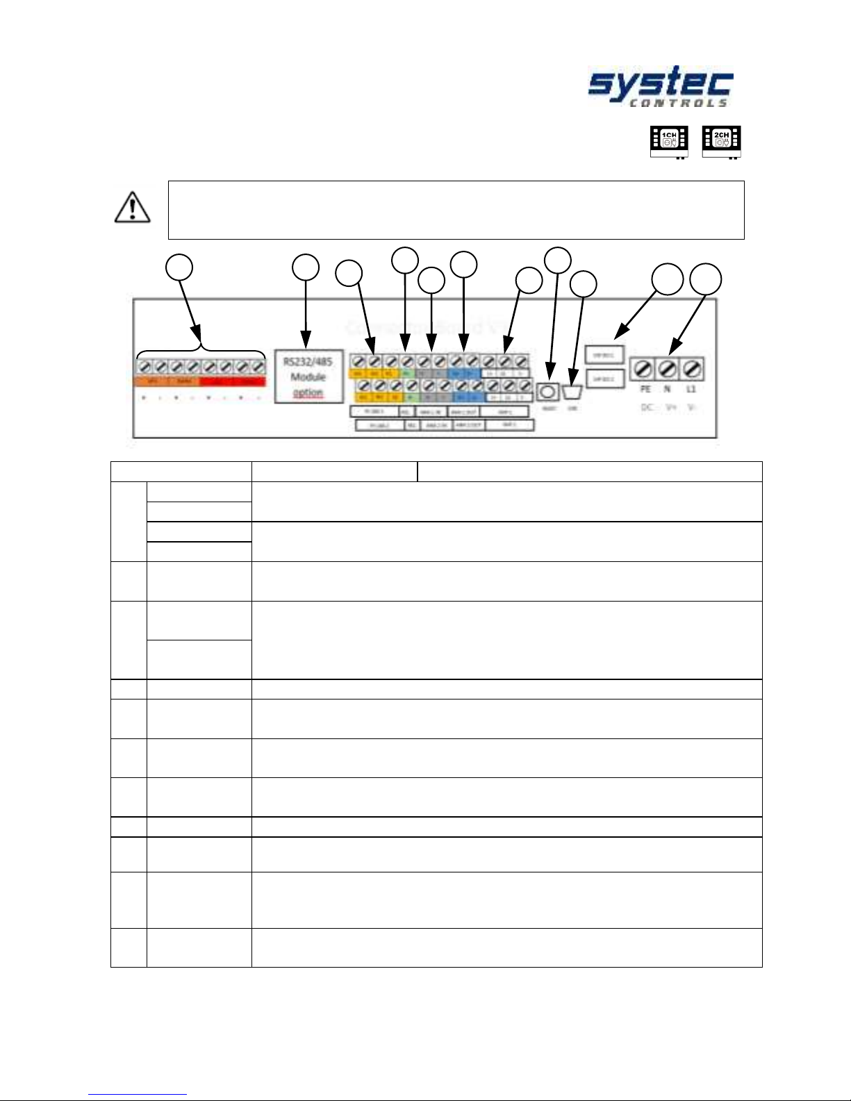
5.2 Overview deltawaveC-F
The overview of the connection area and the terminal diagram corresponds
to the connector board V3.0 (double-pole terminals with additional
analogue inputs). Documentation for older versions can be requested.
Term
Connection
Description
1
UP1
input for ultrasonic transducer measurement path 1
( + ) = red cable (core); ( – ) = black cable (shield)
DWN1
UP2
input for ultrasonic transducer measurement path 2
Only 2-channel transmitter
DWN2
2
RS232 /
RS485
optional + retrofitted (Digital Interface board X1 & X2)
Data transmission via serial communication or Modbus
3
PT100 – 1
(T
input
)
1 pair 3-conductor Pt100 (heat measurement)
W terminals: Sense lines (cables of the same polarity / colour)
R-Terminal: GND cable (different colour cable).
For 3-wire Pt100, bridging the sense connections.
PT100 – 2
T
output
4
REL
Relay connection, passive, potential-free
5
ANA 1 OUT
ANA 2 OUT
Retrofitting requires CTRL-Board V2.2
Analogue inputs: 4 ... 20mA Unit signal, 24VDC, active (optional passive)
6
ANA 1 OUT
ANA 2 OUT
Analogue inputs: 4 ... 20mA Unit signal, 24VDC, active (optional passive)
from CTRL 2.1 according to Namur NE43 (3.8-20.5 mA)
7
IMP 1
IMP 2
Digital output (open collector: 20, 40, 60 ms square pulses)
IMP2 Only 2-channel transmitter usable
8
RESET
Hardware-Reset (Restart of the system)
9
USB
USB Interface (Mini-USB Type B), access to the integrated SD memory card
Windows XP or later versions detect the SD Card as mass storage medium
10
DIP 1 DO
DIP 2 DO
DIP Switch for configuring IMP1 and IMP2
NPN, PNP, push-pull, active / passive
IMP2 Only 2-channel transmitter usable
11
PE N L1
V+ V-
Two power supply options available:
alternating current 90 ... 240 V / AC, direct current 18 ... 36 V / DC
1 2 3 4 5 6 7 8 9
10
11
Page 16
deltawaveC-F/P
Manual
16 systec Controls Mess- und Regeltechnik GmbH
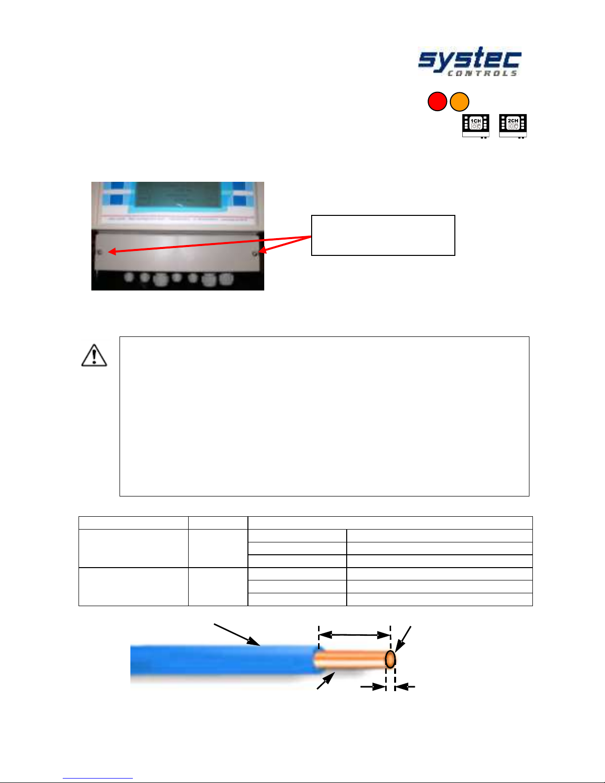
5.3 Connection notes
To access the deltawaveC-F cable space, please detach the cable both screws and
remove the cover plate:
Figure 2: Remove cover from cable compartment
Please always make sure to put the correct voltage to your deltawaveC-F.
Improper supply voltage might seriously damage the flow transmitter.
You can check the type of power supply at the name plate, printed on
right side of enclosure of flow transmitter.
All in- and outputs (except relay) have defined potential on the
internal devices ground. For potential free operation of the in- and
outputs additional hardware is needed (with galvanic isolation). With
the normal in- and output it is not possible!
The analogue in- and outputs are active ex works 24V/DC (could
be set in passive mode by systec controls)
The maximum permitted load of the relay is 45V, 0,25A
Table 1: Recommendations for cable contacts
Terminal designation
description
recommendation
X2
In-/
Output
Cross-section:
0,5 - 4,0 mm²
Diameter:
0,8 - 2,3 mm
Contact length:
8,0 mm
X5
Powersupply
Cross-section:
0,13 - 1,3 mm²
Diameter:
0,4 - 1,3 mm
Contact length:
6,0 mm
Figure 3: Cable assembly
Fastening screws on
cover (cross-slot).
insolation
stripped cable
length
cross section
diameter
Page 17
deltawaveC-F/P
Manual
17 systec Controls Mess- und Regeltechnik GmbH
6 Operating
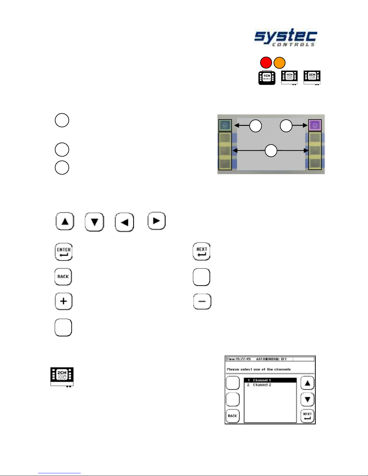
6.1 Control Buttons
Switches the device On and Off. To shut down
the device, press the button for duration of
approx. 3 seconds and then release it. No
function on deltawaveC-F
Switches the backlight On and Off
Multifunctional buttons: Activate the function
displayed beneath the button.
6.2 How to navigate
Use the corresponding multifunctional buttons:
Arrow buttons for navigation
Confirms your entry
Confirms your entries and
opens the next window
Returns you to the previous
window
Triggers the XYZ function
(variable, depending on the
application)
Increases the value
Reduces the value
No function
6.3 Select measurement channel
The operation of the 2-channel transmitter differs
from conventional operation only (in a large part)
through an additional selection of the relevant
channel / measuring path.
3
2
1
1
2
3
XYZ
Page 18
deltawaveC-F/P
Manual
18 systec Controls Mess- und Regeltechnik GmbH
7 First Start
7.1 Basic settings, main menu, navigation
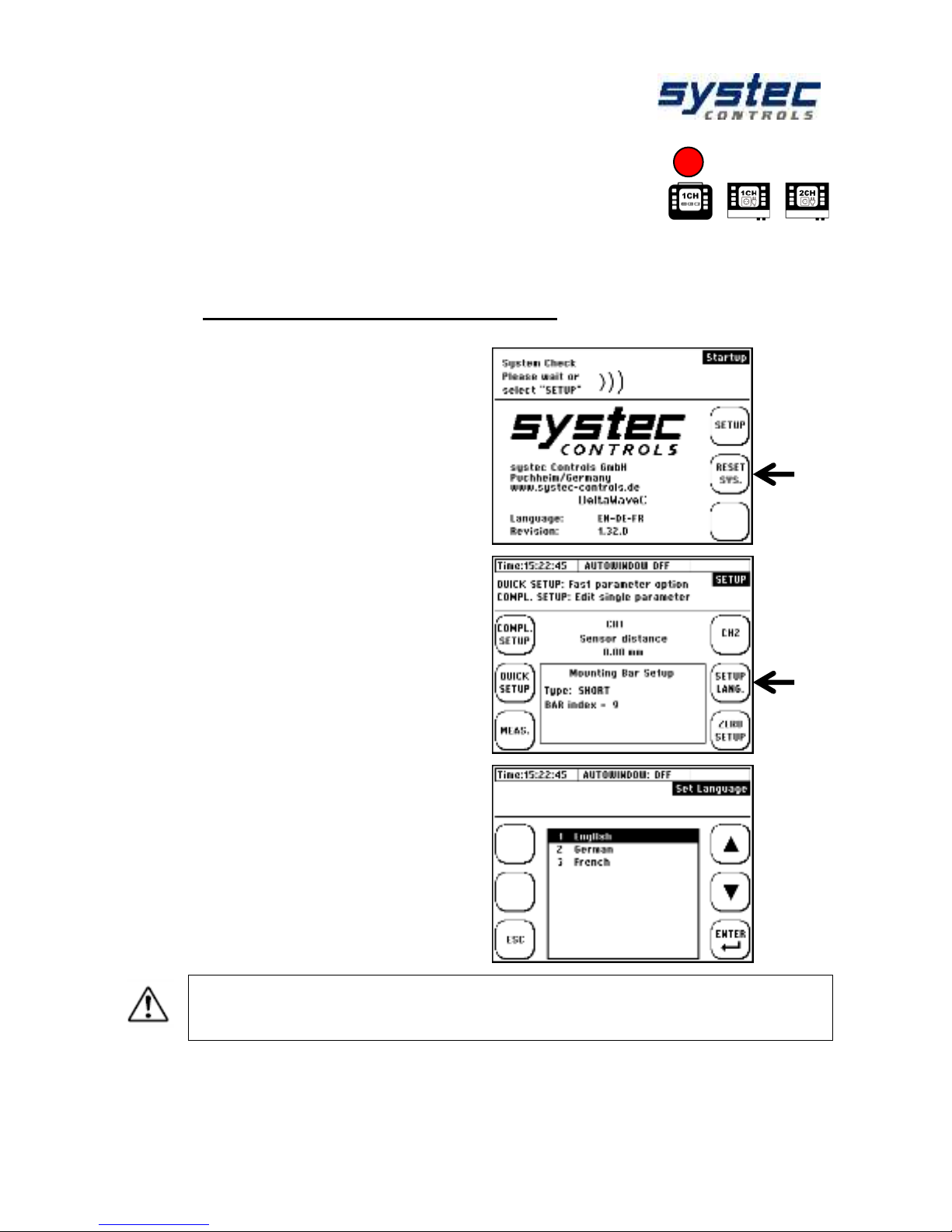
7.1.1 Adjustment of the display language
1. Plug in the device.
During the starting sequence please
press the multifunctional key next to the
section “SETUP”.
2. Press the button “SETUP
LANGUAGE“.
3. In the window choose the required
display language using the arrow keys.
Confirm your input by pressing “ENTER“.
Leave the menu with “SETUP”.
By setting the language you adjust the language used in the menus. The
language in the boxes next to the multifunctional keys remains most widely
unchanged.
Page 19
deltawaveC-F/P
Manual
19 systec Controls Mess- und Regeltechnik GmbH
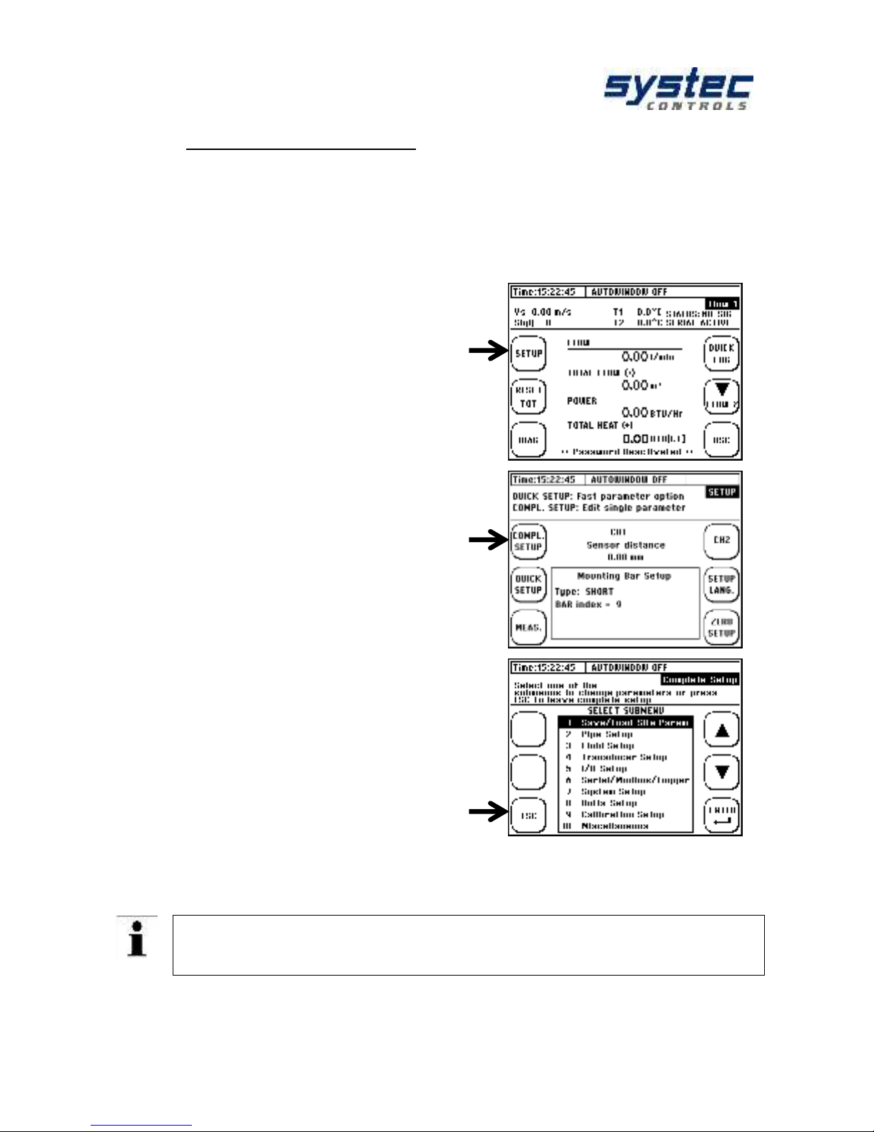
7.1.2 Navigation in main menu
After switching deltawaveC-F/P on and passing through the start screen,
the measuring window “Flow 1” will appear automatically after few seconds.
The measuring window “Flow 1” shows an overview of all necessary
information for the measurement of flow and heat quantity.
1. Select “Setup“.
If the required window does not appear
after pressing “Setup“, please check if the
password function is deactivated.
2. If you can see this window, please
choose “COMPL” Setup“.
3. You are in the main menu now. From
this menu all necessary functions of
the device can be selected.
4. To return to the measuring window
please proceed as follows:
Choose “ESC” -> in the following window
please select “MEAS”.
Now you have become acquainted with the basic operation of your deltawaveC-FP.
There is a trick to reach the main menu even faster after switching the
device on: select “SETUP” during the start sequence right after switching
your deltawaveC-F on. In the following window choose “COMPL” SETUP”.
Page 20
deltawaveC-F/P
Manual
20 systec Controls Mess- und Regeltechnik GmbH
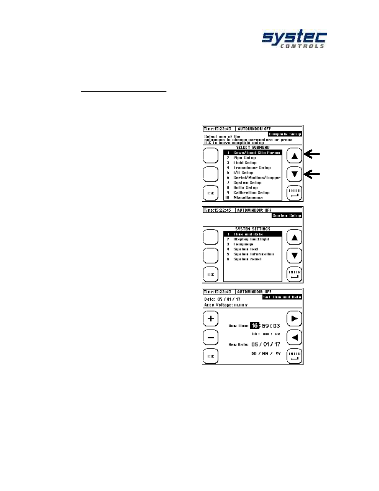
7.1.3 Setting time and date
Having chosen the language for the menu you are in the main menu of the device.
1. Select the menu item (7) System
Settings using the arrow key.
2. In the following window choose menu
item (1) Time and Date.
3. By using the arrow keys the position can
be changed, by using +/- the value can be
adjusted. Please enter the time in the
following format:
Hour(hh) : minute(mm) : second(ss)
Afterwards, please enter the date in the
following format:
Day (dd) : Month (mm) : Year (yy)
4. Subsequently, press “ENTER“ to
confirm your input and return to the system
settings.
Page 21
deltawaveC-F/P
Manual
21 systec Controls Mess- und Regeltechnik GmbH
8 Preparing for measurement deltawaveC-F/P
Set-up your flow measurement in 5 steps
1. Choose suitable mounting position for your transducers
2. Parameterize your flow transmitter
3. Mount ultrasonic transducers onto your pipe
4. Set zero point (if possible)
5. Start your flow measurement
8.1 Preparation of the measurement /
installation location
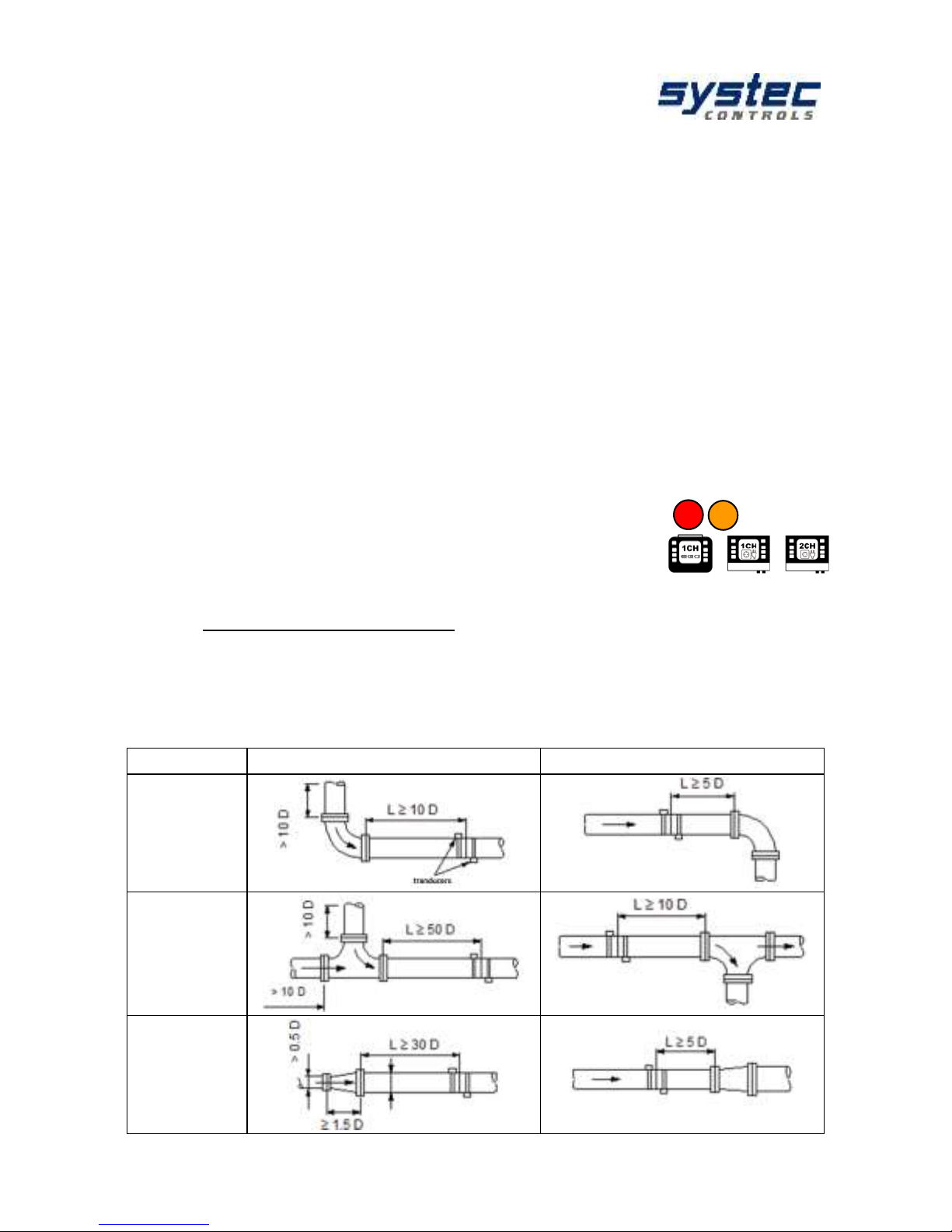
8.1.1 Inlet and outlet distances
The selection of the mounting location has a considerable influence on the quality of
the measurement. Especially the inlet and outlet distance. Please consider the
recommendations in the table below.
The letter "D" stands for the pipe diameter.
Classification
Upstream side
Downstream side
90° bend
Tee
Diffuser
Page 22
deltawaveC-F/P
Manual
22 systec Controls Mess- und Regeltechnik GmbH
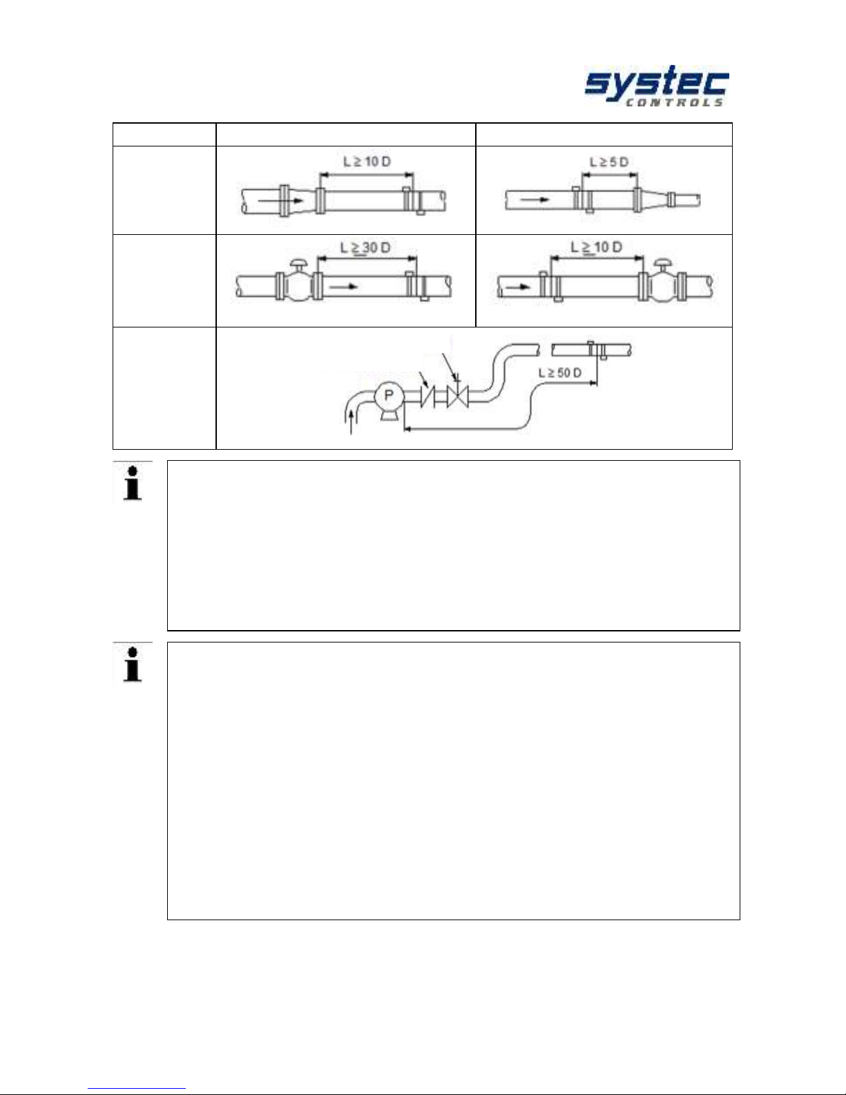
Classification
Upstream side
Downstream side
Reducer
Control valves
Pump
The distance “L” is defined as the distance from a fitting (e.g. a 90° bend) to the
middle of the position of the ultrasonic transducers.
Example: 90° bend (at upstream side) at the inlet, 90° bend (at downstream side) in
the outlet.
Diameter of the pipe: 110 mm
Recommendation according to the chart.
Running-in distance: 10D inlet = 10 x 110 mm = 1100 mm
Running-out distance: 5D outlet = 5 x 110 mm = 550 mm
What happens if the recommended inlet and outlet sections cannot be
complied with?
With simple pipe bends or T-pieces a reduction of inlet or outlet distances leads to a
greater uncertainty of measurement. The closer to the fitting the transducers are
mounted, the greater the measurement error will be.
With higher velocities of flow a shortened inlet section can also lead to lasting
disturbance of the flow profile which can induce a measurement failure. If there is a
temporary measurement failure and there is no possibility to change the mounting
position of the ultrasonic transducers, then the recommendation is to use the next
higher ultrasonic transducer type even with small pipe sizes:
F10 Transducer from DN32…DN200
F05 Transducer from DN200
Pumps or flaps/valves produce permanent disturbances of the flow profile, which are
not improved by switching to a different transducer type. In this case, the
recommended inlet/outlet distances should be adhered to consistently.
pump
back- pressure Vale
stop valve
Page 23
deltawaveC-F/P
Manual
23 systec Controls Mess- und Regeltechnik GmbH
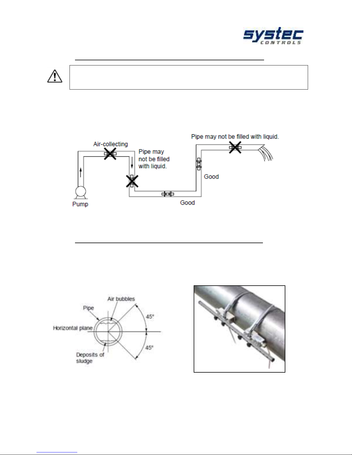
8.1.2 Basic principles for ultrasonic transducer assembly
The pipe always has to be completely filled at the mounting positions
of the ultrasonic transducers!
Measurement of partially filled pipes is not possible!
The ultrasonic transducers can be mounted vertically or horizontally or in any other
position. This is conditional on compliance with the possible mounting positions
shown below:
Figure 4: Preferable mounting positions for ultrasonic transducers (1)
8.1.3 Ultrasonic sensor Mounting on horizontal pipelines
On horizontal piping, it is recommended to mount the transducer with an offset of
approx. +/-45% to the horizontal plane. This is based on the fact that there is a risk
of the accumulation of bubbles in the upper section and sedimentation in the lower
section of the pipe.
Figure 5: Preferable mounting positions for ultrasonic transducers (2)
Page 24
deltawaveC-F/P
Manual
24 systec Controls Mess- und Regeltechnik GmbH
Note on deposits in the pipeline, e.g. Lime:
The flow rate calculation of the deltawaveC-F / P is based on the following formula.
The red-marked term can be seen that the deltawaveC-F/P the entire pipe crosssection includes in the calculation. Your deltawaveC-F/P calculates the pipe crosssection based on the parameterized values from your tube circumference or tube
diameter and wall thickness. If lime scale deposits occur within the pipeline, they
reduce the measurable cross-section through which the fluid flows. This will add an
additional measurement uncertainty.
Especially if the pipe is unknown and/or the documentation of the
application is missing, measuring the thickness of the pipe wall can be
reasonable. In this case, systec Controls offers you the precise pipe wall
thickness measuring device deltawaveC-WD.
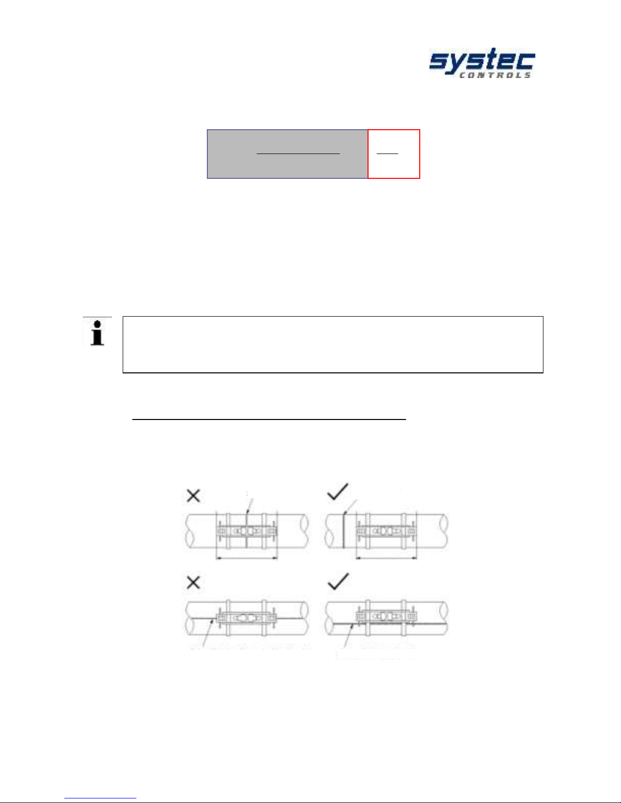
8.1.4 Ultrasonic transducer on uneven surfaces
Avoid mounting the sensors on uneven surfaces such as welds or deformations.
For pipes with thick and uneven protective paint, remove it as far as possible at the
points on which the ultrasonic transducers are mounted.
Figure 6: Preferable mounting positions for ultrasonic transducers (3)
welded joint
welded joint
welded joint outside
welded joint in measurement area
welded joint outside
welded joint partly in measurement area
4cos2
)(
2
Re
12
D
k
tt
t
LQ
Page 25
deltawaveC-F/P
Manual
25 systec Controls Mess- und Regeltechnik GmbH
8.2 Fundamentals of parameterization
The Parameterization chapter defines the input of all data that is necessary for flow
measurement.
1. „QUICK SETUP“: The Quick Setup guide offers step-by-step instructions on the
essential tasks you have to complete for deltawaveC-F/P parameterization. This
Quick Setup is quite sufficient for handling most applications and gets you started
with fast and efficient parameterization in no time at all.
2. „CMPL SETUP“: The complete setup function enables access to all options and
expert settings. Here, you can also directly access individual parameters via the
main menu.
What needs to be parameterized?
1. The pipe's outer diameter or circumference.
2. The wall thickness of the pipe. The material and thickness of the pipe
lining, if such lining exits.
3. The pipe material
4. The medium
5. The type of ultrasonic transducers
6. The mounting mode for the ultrasonic transducers
Ultrasonic measurement is based on the signal transit time process. The
ultrasonic signals penetrate the piping and the medium. In order to
calculate the signal transit time, each medium, piping material and existing
lining will be assigned a sonic speed value, as well as the pipe diameter or
circumference value.
The deltawaveC-F/P has stored tables in which the sound velocities of
materials and media are stored. If the material or medium is not listed in the
tables, its sound velocity must be entered manually. At the end of this
manual you will find tables with additional sound velocities for different
substances.
Page 26
deltawaveC-F/P
Manual
26 systec Controls Mess- und Regeltechnik GmbH
8.3 Parameterization with the Quick Setup
How to access the parameterization dialog:
After power on: Select „Setup“ „Quick Setup“
In the primary measuring window "Flow 1": Select "Setup" "Quick "Setup".
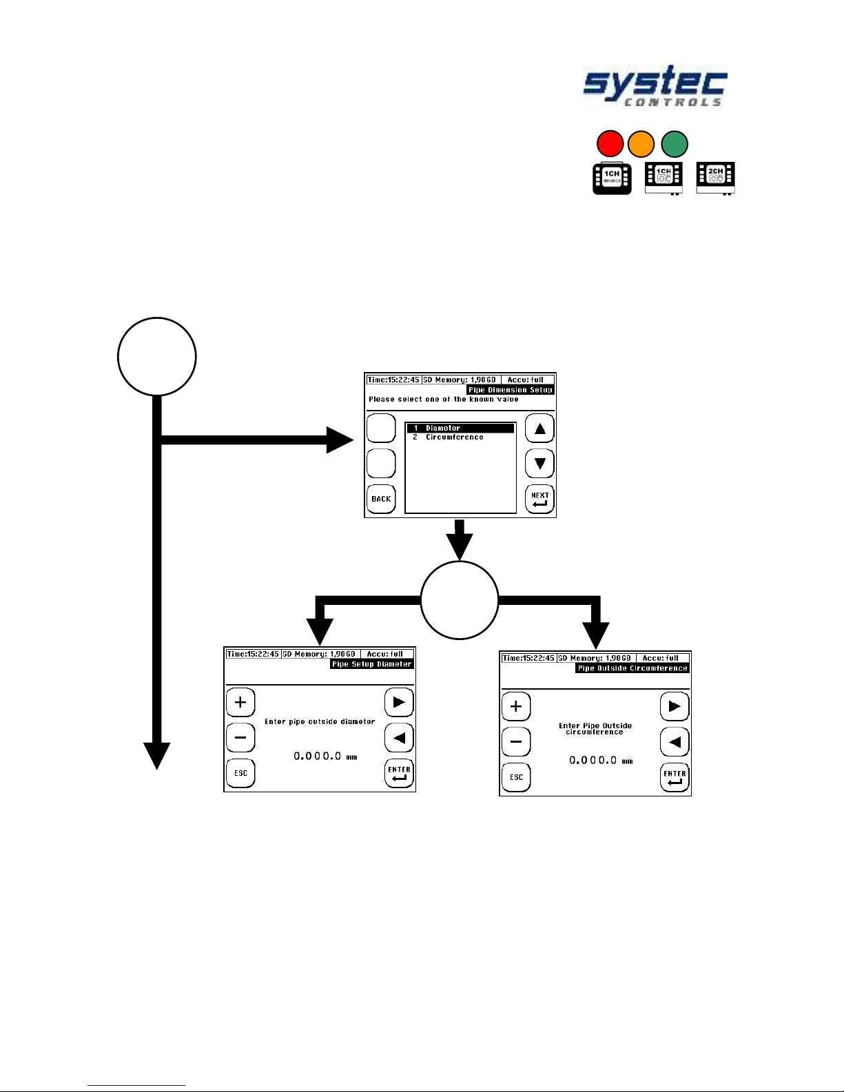
1
Specify whether to enter the pipe circumference or outer
diameter:
or
Enter the outside diameter
Enter the diameter
Page 27
deltawaveC-F/P
Manual
27 systec Controls Mess- und Regeltechnik GmbH
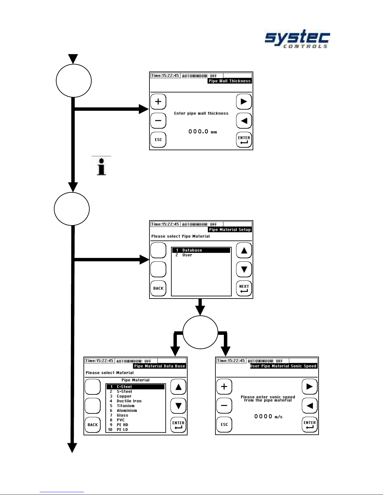
OR
Enter the pipe's wall thickness:
Choose pipe material:
Choose the pipe material Enter the sonic speed
from the database from the pipe material
Database from: manually:
It is advisable to use a wall thickness meter if you do not
know this parameter.
2
3
Page 28
deltawaveC-F/P
Manual
28 systec Controls Mess- und Regeltechnik GmbH
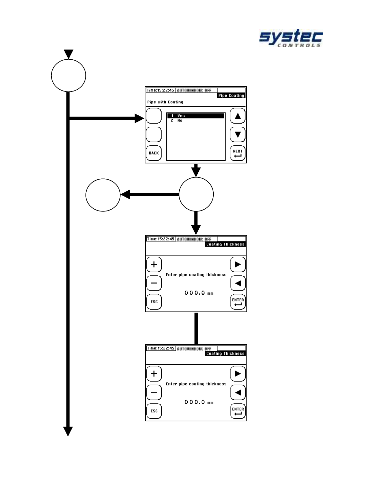
OR
Does the pipe have a Coating
NO
Enter the thickness of the YES
pipe
Select the database,
or user input if material
is not listed in the database
4
5
Page 29

deltawaveC-F/P
Manual
29 systec Controls Mess- und Regeltechnik GmbH
Select the medium:
5
Select the database, for
coating material
Enter the coating sonic
speed of the material
OR
Select the fluid, from the
database
Enter the fluid sonic
speed manually
OR
Page 30
deltawaveC-F/P
Manual
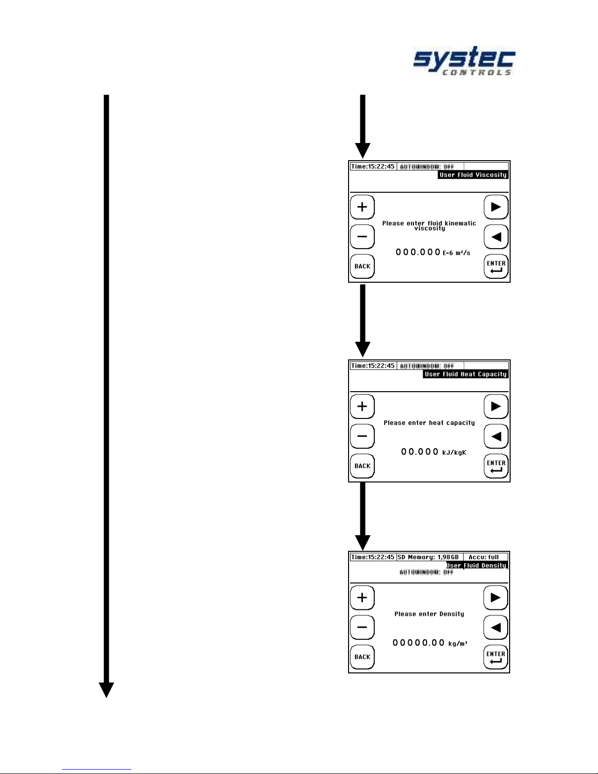
30 systec Controls Mess- und Regeltechnik GmbH
Enter the kinematic
viscosity of the
medium:
Enter the thermal
capacity of the
medium
Enter the density of
the medium
Page 31

deltawaveC-F/P
Manual
31 systec Controls Mess- und Regeltechnik GmbH
Select a suitable ultrasonic transducer:
Select a suitable mounting mode
For information on suitable transducers for specific pipe
dimensions, refer to chapter "deltawaveC-F/P and
components“.
6
7
Page 32

deltawaveC-F/P
Manual
32 systec Controls Mess- und Regeltechnik GmbH
Output of the distance between the ultrasonic transducers:
END
Important!
Please do always take care which mounting bar for transducers is
displayed. The displayed one bar must be used:
Short = 25cm, hole distance 7,5mm, (XUC-FW F21)
Long = 40cm, hole distance 15mm, (XUC-FW F10, F20)
The sensor distance in millimetres is always the distance between
the front edge of the ultrasonic transducer 1 (UP) to the front edge
of ultrasonic transducer 2 (DOWN) independent from the chosen
method of mounting.
The standard mounting type is "V-mounting".
Information on the mounting types can be found in the
chapter "Preparation for measurement".
Before you start
measuring we
highly
recommend a
zero setup (if
possible)
8
Page 33

deltawaveC-F/P
Manual
33 systec Controls Mess- und Regeltechnik GmbH
8.4 Sensor assembly / Sensor distance
The distance between the ultrasonic transducers is always measured between their
opposing surfaces in all mounting modes. Once you have completed the
parameterization of the measuring point, the flow transmitter displays the distances
that have to be set up using a measuring tape. When using a spacer bar in the socalled V-mode, you can position the transducers conveniently by means of the
spacer bar.
8.4.1 Introduction to the installation of ultrasonic transducers
Principle composition of the ultrasonic transducers:
Ultrasonic transducers (F05, F10 and F20/F21) is beige and made of plastic
(PEEK).
deltawaveC-F
deltawaveC-P
Figure 7: Principle composition of the ultrasonic transducers: 1: basic body, 2: cover, 3:
connection cable (RG316), 4: knurled screws for fixing on the mounting rail, 5: knurled screw
(variation of contact pressure), 6: support housing ("portable" type), 7: BNC connector (RG58,
female, "portable" type), 8: projection of the acoustic transmission surface
1 2 3 4 8
2
7
1
6
4 5 7
8
Page 34

deltawaveC-F/P
Manual
34 systec Controls Mess- und Regeltechnik GmbH
8.4.2 Mounting ultrasonic transducer
This chapter informs you of the possibilities for mounting the ultrasonic transducers.
The V-mode is standard for most applications.
V-Mounting
V-mounting results in a measurement in most
applications and is often the best compromise
achievable signal quality and accuracy.
W- Mounting
W-Mounting assembly is used when a
measurement result which is as exact as
possible and/or a high resolution is to be
achieved.
In the case of small pipe sizes, this mounting
type can also be useful due to the signal sensor
separation
Z- Mounting
Z-Mounting assembly is due to the minimal
signal path typically for large pipes or very dirty
or gas-loaded media with high signal
attenuation or signal dispersion for use
contaminants.
NO MOUNTING BAR
In some cases Z-mounting results in successful measurements on small pipe
diameters (< 20 mm) as well: if the received signals (pipe wall/V/W) can no longer
be unambiguously unselected or when the correct reception signals in the
measurement window cannot be uniquely positioned (look at 14.2.3)
Figure 8: Z-mounting example, only possible
without mounting rail (XUC-FW)
Figure 9: V- and W-mounting example
with mounting rail (XUC-FW)
Page 35

deltawaveC-F/P
Manual
35 systec Controls Mess- und Regeltechnik GmbH
8.4.3 Correct selection of transducer types
Below you will find a guide for the correct ultrasonic transducer selection, which has
proven to be successful in practice.
Pipe diameter
Transducer
Systematic
Comment
D < 35 mm
F21 Transducer
( ** )
35 mm > D < 110 mm
F10 Transducer
F21 Transducer
( ** )
( * )
110 mm > D < 250 mm
F10 Transducer
( ** )
250 mm > D < 400 mm
F10 Transducer
F05 Transducer
( ** )
( * )
D > 400 mm
F05 Transducer
( ** )
Systematic: ( ** ) –Best selection; ( * ) second best selection
8.4.4 Correct selection of mounting options
Below you will find a guide for the correct choice of mounting options, which has
proven to be successful in practice.
Pipe diameter
Mounting option
Systematic
Comment
D < 40 mm
W- Mounting
V- Mounting
Z- Mounting
( ** )
( * )
( * )
40 mm > D < 130 mm
W- Mounting
V- Mounting
Z- Mounting
( ** )
( ** )
( * )
If the SNR good
Disturbed signal
130 mm > D < 400 mm
V- Mounting
Z- Mounting
( ** )
( * )
D > 400 mm
V- Mounting
Z- Mounting
( ** )
( * )
If the SNR good
Systematic: (**) highest accuracy; (*) higher signal strength
Page 36

deltawaveC-F/P
Manual
36 systec Controls Mess- und Regeltechnik GmbH
8.4.5 Mounting of the Transducer in V-Mode or W-Mode
After the parameterization of the measuring point, the transmitter shows the
distance of the transducers in mm and the number of holes. The number of holes is
a reference quantity of the distance with simultaneous application of the mounting
rails for the ultrasonic transducers F10, F20 and F21.
There are two different lengths of mounting bars with different grid dimensions:
Short Bar = 40cm, hole distance 15mm (only for F10 and F20 Transducer)
Long Bar = 25cm, hole distance 7,5mm (only for F21Transducer)
For example: The whole number is „3“, this corresponds to the number of holes
between the ultrasonic sensors plus the position at which the thumbscrew of the
opposing transducer is mounted. Mount the sensors on the rail as shown. Fix the
transducers to the rail using the knurled screws (B).
deltawaveC-F
Example of the number of holes 3
deltawaveC-P
Example of the number of holes 5
If the wrong mounting rail is used or the wrong hole distance, the
measurement does not work or incorrect values are displayed!
0 1 2 3 4
5
0 1 2
3
Page 37

deltawaveC-F/P
Manual
37 systec Controls Mess- und Regeltechnik GmbH
deltawaveC-F
deltawaveC-P
For the long-term installation of transducers
only the coupling pads are recommended.
Place one acoustic coupling pad between
the acoustic transmission surface of the
transducer and the pipeline for each
ultrasonic transducer.
Do not use any additional coupling media
such as gels or pastes!
Make sure that the coupling pads lie flat on
the complete sensor surface.
Turn the thumbscrew max out, so that the
transducer base is located below the lower
edge of the sensor carrier (V-profile)
Apply a peanut-sized drop of ultrasonic
coupling gel (Magnalube) to the acoustic
transmission surface (offset downwards) and
rub it slightly.
Figure 10: XUC-FW F10 with acoustic
coupling pad
Figure 11: Transducer with an approx.
peanut-sized drop of coupling gel
The coupling gel allows a significantly better signal quality than the acoustic
coupling pads. However, high temperature signal, the coupling gel may run
and the acoustic signal coupling can be lost.
In this case a thermally stable coupling gel or acoustic coupling pad can be
used - contact systec Controls.
The coupling pads are stable long-term and allow for a sufficiently good
signal quality in most cases when used correctly. Use acoustic coupling foil
exclusively for ultrasonic transducers for fixed installation.
For optimum signal coupling, a higher contact pressure is necessary, which
usually cannot be produced with the mounting means of the portable
measuring device.
In rare cases it may happen that the use of an acoustic coupling gel proves
to be more appropriate than the acoustic coupling pads:
- Pipe surface with high roughness
- rapid flow of the coupling gel at high thermal loads
Page 38

deltawaveC-F/P
Manual
38 systec Controls Mess- und Regeltechnik GmbH
deltawaveC-F
deltawaveC-P
The ultrasonic transducers are attached by
stainless steel band on the pipeline. The
stainless steel tensioning band is designed
for the maximum diameter of the tube to be
used for your ultrasonic transducer and
tensioned via the tensioning buckle.
The tensioning band can be shortened
easily for smaller pipes.
To attach the ultrasonic transducers (with
or without the mounting rail), use the
stainless steel chains or hook-and-loop
bands.
The knurled screw is tightened in a
clockwise direction until a slight pressure
is applied
Figure 12: Mounting of XUC-PW with
stainless steel chains; 1: tension spring, 2:
hook for fastening
Figure 13: Mounting of XUC-FW with
stainless steel band; 1: clamping tool, 2:
clamping lock, 3: clamping band.
8.4.6 Mounting the ultrasonic transducers based on the Z method
Use a plastic or paper template to mark the mounting positions.
1. Wrap the plastic template once around the pipe at the mounting position of the
first ultrasonic transducer. Using a felt tip pen, draw a line on the pipe along the
template (corresponds with the pipe circumference)
Figure 14: Attaching the template tape
Figure 15: Mark the circumference
2
1
1
2
3
Page 39

deltawaveC-F/P
Manual
39 systec Controls Mess- und Regeltechnik GmbH
2. • On successful completion of parameterization, your deltawaveC-P/F
displays the axial distance between the ultrasonic transducers (transducer
distance). Measure the transducer distance based on the value displayed on your
deltawaveC-P/F, starting from the first line drawn to the position at which the
second line is to be drawn.
Figure 16: Mark the distance between
transducer
Figure 17: Mark the circumference for the
second transducer.
3. On the circumference lines, select
two exactly opposite positions.
4. Mount the first sensor to the centre
of mark 1.
5. Measure out the half of the pipe
circumference along the circumference
line from mark 2 and apply marking 3.
Figure 18: Opposed marks 1 & 2 at the
circumference lines
2
2
21
r
U
6. Mount the second sensor to the centre of the sensor front (not the sensor) at
mark 2 (see Figure 19 & Figure 20). The sensors are now exactly opposite.
1
2
Page 40

deltawaveC-F/P
Manual
40 systec Controls Mess- und Regeltechnik GmbH
Figure 19: Mark the position of the second
transducer at half circumferential distance
Figure 20: Mounted transducer, Z-mounting
8.4.7 Mounting the ultrasonic transducers at two
crossed measuring paths
The mounting type of both pairs of transducers must be the same (V-mounting, Wmounting or Z-mounting). It is not possible to combine different mounting methods.
For Z-mounting the transducers of the respective pair must be offset by 180 °. For V
and W mounting, the transducers of the respective pair are mounted on the same
side of the tube. Installation instructions for the exact alignment at 180 ° offset can
be found in the Z-type mounting aid (8.4.6).
3 1 2
3 1 2
Page 41

deltawaveC-F/P
Manual
41 systec Controls Mess- und Regeltechnik GmbH
8.5 Zero Setting
Before starting the measurement, we recommend performing a zero calibration.
Prerequisites for zero-point calibration are:
- that the device is configured correctly and that both ultrasonic
transducers are mounted properly on the pipe and electrically
connected to the transmitter
- the line is completely filled
- the flow rate is zero
If all prerequisites are fulfilled, perform a zero-point calibration, otherwise,
do not perform a zero-point calibration!
An incorrect zero point adjustment will have a more negative impact on the
measurement result than no zero adjustment!
Procedure:
1) Ensure zero flow
2) Navigation after switching on:
„Setup“ „Zero- Setup“
From the measuring window "Flow 1" outgoing:
„Setup“ „Zero Setup“
From the main menu "COMPL. SETUP"
outgoing: „Miscellaneous“ „Zero“ „Set Zero“
3) The zero point adjustment starts automatically.
Wait until the counter reaches the value "0" again.
4) After confirming (ENTER) the time correction of
the zero point adjustment, you are returned to the
"Setup" window.
Typical values for the zero point adjustment are generally in single-digit
range.
If you receive a "time correction" in two-digit range (and more), you can
assume that a (residual) flow was present during the zero-point adjustment.
The zero point will be automatically deleted when relevant parameters
(parameters pipe, parameter medium and parameter converter) have
been edited again.
Page 42

deltawaveC-F/P
Manual
42 systec Controls Mess- und Regeltechnik GmbH
You can check the detected zero point by navigating from the "Flow 1"
measurement window to the diagnostic window. In the measurement window, select
“Flow 1“ „DIAG“
The zero point remains stored in the device until it is automatically
overwritten with a new zero offset or has been removed manually by
"Delete zero".
The time correction value of the zero point adjustment is an essential part
of the parameter structure (see 11.1 Saving/Loading parameter data).
The zero point will be automatically deleted when relevant parameters
(parameters pipe, parameter medium and parameter converter) have been
edited again
For zero-point calibration, your deltawaveC-F/P determines the run-time
difference at zero flow, which can arise between the sensors and, if
necessary, a flow which is still present.
This determined time (dt ZERO) is automatically compensated in the flow
measurement. This increases the accuracy of your flow measurement. dt
ZERO is sign-loaded - a subsequent exchange of up- and downtransducers would thus double the error. The ultrasonic sensors are paired
at the factory and have a very low zero point error (typically <2 ns).
A zero flow rate cannot be guaranteed at every position of the pipeline
system. When installed carefully, this error is in the range of 0.00-0.03 m /
s flow velocity. The larger the pipeline is, the smaller is usually the zero
point error.
9 Heat measurement
Page 43

deltawaveC-F/P
Manual
43 systec Controls Mess- und Regeltechnik GmbH
The integrated heat quantity measurement allows you to determine the heating or
cooling power in your application using with the optionally available Pt100.
9.1 Introduction
The Pt100 No. 1 is mounted on the input side (T1 = Tin), Pt100 No. 2 at the output
of the process section (T2 = Tout). The placement of the ultrasonic sensors is
irrelevant as long as the volume flow is equal. There should be a pipe section to be
selected with optimal inflow / outflow (look at chapter 8.1.1).
Figure 21: Scheme of heat quantity measurement
The deltawaveC-F/P shows you the heat output and the accumulated heat quantity.
Calculating thermal output
The cross-sectional area of the pipe's inner diameter [A] is multiplied by the flow
velocity [v] and specific thermal capacity of the medium [c], as well as the
or
deltawaveC-F
deltawaveC-P
heat / power
volume / volume flow
Pt100
T2
Pt100
T1
outlet
temperature
inlet
temperature
ultrasound
transducer
Q… volume flow
Pin
P
out
determination of
heat quantity
Page 44

deltawaveC-F/P
Manual
44 systec Controls Mess- und Regeltechnik GmbH
dtQQ
TTcvAQ
coldhotw
)(
differential temperature of both Pt100, [Tout – Tin]. The product defines thermal
output [Q] in W units.
)( inoutw TTcvAQ
][kWQ
Calculating heat (quantity)
The heat quantity is derived as a function of thermal output over time.
]/,[ hkWJQ
9.2 Installing the Pt100
The Pt100 are mounted on the pipeline using the supplied stainless steel tapes.
Figure 22: At pipe mounted Pt100
It is irrelevant whether you attach the Pt100 to the pipeline with the longer
or shorter side of the housing.
For the determination of the heat quantity the determination of the correct
temperature difference is important (relative measurement). This means
that the temperature readings can deviate absolutely relative to a reference
(for example, against an immersion thermometer).
It is important to calibrate both Pt100 and to ensure that both Pt100 show
the same measured value in a volume of the same temperature (the
difference between the Pt100 before the installation on the pipeline should
be zero degree).
The thermal insulation or the use of thermal grease during assembly of the
Pt100 can significantly reduce the measurement uncertainties when
determining the temperature difference.
Page 45

deltawaveC-F/P
Manual
45 systec Controls Mess- und Regeltechnik GmbH
9.3 Parameterization of the Pt100 for the
heat quantity measurement
Before installing the temperature sensors on the pipeline, the temperature
difference between both Pt100 should be approximately zero degree in a volume of
thermal equilibrium.
We recommend that both temperature sensors be immersed in a tube with liquid for
approx. 2...5 minutes (the liquid should be at room temperature) before the tubes
are mounted on a pipeline. Avoid touching the probes in advance of the calibration.
To check the calibration, please use the display in "Measuring window 3", "Heat
quantity", as the temperature difference between T2-T1 is displayed in this
measuring window. After calibration, the temperature difference should not be > 0.2
° C (2 / 10K). If the temperature difference is higher, repeat the calibration
procedure.
Further information on the parameterization of the Pt100 can be found in the
chapters 11.9.2, 11.9.3 and 11.10.1.
In addition to the zero adjustment, the individual temperature readings can be offset
(adjustment to reference value / compensation of deviations).
Example: In the pipeline there is a resistance thermometer which shows
80°C. However, your deltawaveC-F/P contact resistance thermometer
Pt100 shows only 78.5 ° C. The difference can be corrected manually. In
this case, you specify a default value of 80 ° C. The default value is an
absolute value and no offset.
The parameterized clamped value is valid for both Pt100. The temperature
measurement is clamped with one second (average value formation). For low
measuring dynamics and small temperature differences between Pt100 No. 2 and
No. 1, it is recommended to increase the Pt100 clamping value. An increase in the
clamping has a positive effect on the stability of the temperature difference
measurement.
Page 46

deltawaveC-F/P
Manual
46 systec Controls Mess- und Regeltechnik GmbH
10 Measuring windows deltawaveC-
F/P
10.1 Headline
The header is the same for each of
the three measurement windows and
displays basic values and status
messages:
1) General information
2) General measurement values
3) Name of the UI window
4) Status display
5) Status display for communication
Display
Explanation
Gen. Inform.
Time
Format: hh:mm:ss
AUTOWINDOW
ON / OFF
Auto window function
IOE
Indicates that the memory for the pulse output is full and the pulse
output is disabled (look at chapter 11.5.4).
Battery condition :
Battery is charging ; 50-100%; 25-49%; 10-25%; <10%
Value
s
Vs
Sound velocity of medium in m/s
SigQ
Signal quality (percentage of valid signals)
T1 / T2
Temperature values of the Pt100
Communication
MODBUS ON
MODBUS OFF
Status for the MODBUS communication.
Priority over SER SST. status.
SER. SST. ON
SER. SST. OFF
Status display for serial communication.
Priority over LOGGER status.
LOGGER ON
LOGGER OFF
Status display for the data loggers.
Priority over USB status.
USB ON
Indicates that the USB interface is connected to an external master.
QLOGGER ON
Indicates that the Quick Logger is active.
Measurement
OK
Everything OK. Valid signals are evaluated.
NO SIG
No valid signals present.
Error
Problems with the ultrasound board. Possible reasons: defective, DSP
update necessary.
VS ERR
0.8 * Vs parameterized <Vs> 1.2 * Vs parameterized
Possible reasons: wrong signal (W instead of V, V instead of W)
VP / VL ERR
Error in the calculation of the signal propagation.
1 2 3
4
5
Page 47

deltawaveC-F/P
Manual
47 systec Controls Mess- und Regeltechnik GmbH
10.2 Measuring window "Flow 1"
In the flow measurement window 1 you get all the important information, compactly
summarized for your flow, heat output and heat quantity measurement.
Navigation in the User-Interface:
1) Approximately 10 seconds after
switching on, it will automatically switch
from the home screen to the central
measuring window "Flow 1".
2) From the main menu, starting:
Select "ESC" then "MEASURE."
Display
Explanation
FLOW
Displays the current volume flow
TOTAL
FLOW
Totalizer flow = flow meter
(Summed up volume)
Parameterizable types: Sum counter (+), negative counter
(-), absolute counter (+/- sum), difference counter (+/- diff)
POWER
Displays the current heat output.
HEAT
TOTAL
Totalizer heat quantity = heat quantity counter
(Summed heat quantity)
Parameterizable types: Sum counter (+), negative counter
(-), absolute counter (+/- sum), difference counter (+/- diff)
Password activated/
deactivated
Status of password protection.
Switch to the setup window
ONLY portable: activates
the Quick-Logger
Sets the totalizer (flow and heat
quantity) to zero.
Change to measuring window
"Flow 2".
Switch to diagnostic window.
Switch to the oscilloscope
window.
Page 48

deltawaveC-F/P
Manual
48 systec Controls Mess- und Regeltechnik GmbH
10.3 Measuring window "Flow 2"
In the flow measurement window 2 you get all the important information, compactly
summarized for your flow measurement (without heat measurement).
Navigation in the User-Interface:
From the main measurement window
"Flow 1" outgoing: Select "Flow 2"
Display
Explanation
FLOW
Displays the current volume flow
Fluid
VELOCITY
Indication of the flow velocity of the medium in the pipe
TOTAL
FLOW
Totalizer flow = flow meter
Parameterizable types: Sum counter (+), negative counter
(-), absolute counter (+/- sum), difference counter (+/- diff)
Password activated/
deactivated
Status of password protection.
Switch to the setup window
Change to measuring window
"Flow 1".
Sets the totalizer (flow and heat
quantity) to zero.
Change to measuring window
"heat quantity".
Switch to diagnostic window.
Switch to the oscilloscope
window.
Page 49

deltawaveC-F/P
Manual
49 systec Controls Mess- und Regeltechnik GmbH
10.4 The measuring window "heat quantity"
In the "Heat quantity" measurement window, you get all the important information,
compactly summarized for your heat quantity measurement.
Navigation in the User-Interface:
From the main measurement window
"Flow 1" outgoing: Select "Flow 2" then
„Heat“
Display
Explanation
FLOW
Displays the current volume flow
POWER
Displays the current heat output
HEAT
TOTAL
Totalizer heat quantity = heat quantity counter
Parameterizable types: Sum counter (+), negative counter
(-), absolute counter (+/- sum), difference counter (+/- diff)
DIFF.
TEMPERATURE
Displays the currently measured temperature difference
Password activated/
deactivated
Status of password protection.
Switch to the setup window
Change to measuring window
"Flow 2".
Sets the totalizer (flow and heat
quantity) to zero.
Switch to the password window
(Activation / deactivation)
Switch to diagnostic window.
Switch to the oscilloscope
window
Page 50

deltawaveC-F/P
Manual
50 systec Controls Mess- und Regeltechnik GmbH
10.5 Password protection
The deltawaveC-F/P is equipped with password protection. After enabling
password protection, it is only possible to switch between the measurement
windows and the password display. Parameters or totalizers cannot be
changed when password protection is activated.
Activation of the password:
To access the password display, navigate to the last measurement window.
The following screen is the password window.
Please select "Activate password" or "Deactivate password" and confirm
the function with the "Enter" key.
Edit the number code by using the arrow
(navigation), as well as "+" and "-" (zoom in /
out) buttons. Press "ENTER" to confirm the
entered password. For security reasons, a
second password request is made. Re-Enter
the code and confirm. After that the
password protection is activated or
deactivated depending on the function
selected.
If you have lost/forgotten your password and you can´t deactivate
password protection then please contact systec Controls.
Page 51

deltawaveC-F/P
Manual
51 systec Controls Mess- und Regeltechnik GmbH
10.6 The measurement windows of the 2channel deltawaveC-F
Navigation in the User-Interface:
1) Approximately 10s after power-up the
screen automatically switches from the
start screen to the central measurement
window "CH1 / CH2".
2) From the main menu: Choose
"ESC" then "MEASURE."
CH1/CH2
CH1&CH2
(CH1+CH2)/2
The individual results are shown in the individual measurement windows in
terms of flow velocity, volume flow, totalizer (volume and heat quantity) and
power. Either for the individual channel or according to the illustrated
calculation (sum, difference or mean value)
Switch to the setup window
Switch to the password window
(Activation / deactivation)
Sets the totalizer (flow and heat
quantity) to zero.
Switch the measurement
channel „CH1&CH2“
Switch the measurement
channel „CH1/CH2“
Switch the measurement
channel „(CH1+CH2)/2“
Switch to diagnostic window.
(after CH-Selection)
Switch to the oscilloscope
window
Page 52

deltawaveC-F/P
Manual
52 systec Controls Mess- und Regeltechnik GmbH
11 The main menu (complete menu)
11.1 Loading, saving and managing
parameter data
Navigation in the User-Interface:
From the main measurement window "Flow 1":
select „SETUP“ then „COMPL SETUP“ select
„Save/Load Site Param“
Your deltawaveC-F/P offers you the possibility to
save, load and display all relevant parameters. This
saves time when you need to perform
measurements of recurring measuring points.
Via the "file access", up to 9 parameter sets can
be stored and made available as a parameter file "*
.PAR" on the SD card. The format corresponds to a
text file ("* .txt") and can be visualized and edited at
any time via a text editor or a spreadsheet program.
To select a parameter set, use the arrow keys to
select a memory location and confirm with "Next".
You now have the option to check all parameters
before saving. The parameter data is distributed
over 7 measurement windows. To switch between
the parameter data, use the arrow key.
IMPORTANT
The parameter overview shows the current contents
of the PAR file. To ensure that the content matches
the current parameters, the current parameter set
must first be saved in the corresponding file.
Page 53

deltawaveC-F/P
Manual
53 systec Controls Mess- und Regeltechnik GmbH
Resetting the PAR file name and
content
Save the current parameter data
Switch between the overview
windows
Switch to edit file name
Back to file list
Loading the PAR content
Edit the file name:
1) Use the arrow keys to select characters that
correspond to the PAR file name (max. 7
characters)
2) Press "ENTER" to confirm the selection of a
character
3) "DEL" clears the last character.
4) Exit by navigating to "DONE" and confirm with
"ENTER“
The new name is only accepted when the "Save" function is activated in
Overview 1.
The "Default.PAR" file is regularly overwritten with the current parameters
(cyclical saving of the current settings) so that this memory space should
not be used.
The parameter data are stored from firmware 1.33.x on the device-internal
SD memory card and can be exported via USB.
The copying / saving of parameter files from the device-internal SD card are only
possible via the USB interface. As soon as the transmitter is connected to a PC via
USB, the SD card is recognized as an external data memory and data can be
exchanged.
The system only registers "known" PAR files.
If a parameter file is to be transferred from a deltawaveC-F/P (device 1) to
a different device (device 2) via USB, it must be ensured that the name of
the PAR file is assigned to one of the names from the list of Device 2 (see
file access, e.g.: FILE1.PAR). The file (device 2) can then be directly
replaced / overwritten.
Systec Controls recommends storing and backing up parameter sets of
important or recurring applications. This saves time and enables fast,
efficient assistance in cases support where support is needed
During the year 2017, a software tool will be available that allows
convenient creation and editing of parameter files. If you are interested,
please contact systec Controls.
Page 54

deltawaveC-F/P
Manual
54 systec Controls Mess- und Regeltechnik GmbH
11.2 The pipe parameters
Navigation in the User-Interface:
From the main measurement window "Flow 1":
select „SETUP“ then „COMPL SETUP“ select
„Pipe Setup“
The pipe parameters are part of the Quick Setup
(mandatory parameters), but can also be edited
individually via the main menu.
Pipe Setup
outside diameter
outside Circumference
or
Enter
outside diameter
Enter
outside Circumference
Enter wall thickness
Pipe material
from data base
User defined
pipe material
or
Does the pipe have an internal liner?
YES
NO
or
Thickness of liner
Liner material
Liner material
User defined
or
E N D
Page 55

deltawaveC-F/P
Manual
55 systec Controls Mess- und Regeltechnik GmbH
Parameterization of a user-defined pipe
material:
Scroll down in the material database
Here are freely editable materials:
Pipe: 7x PMAT
Pipe Lining: 4x LMAT
Both the name and the properties can be changed
with these materials.
To edit a custom material, you need:
1) Sound velocity (longitudinal)
2) Poisson's ratio
11.3 The Fluid Setup
Navigation in the User-Interface:
From the main measurement window "Flow 1":
select „SETUP“ then „COMPL SETUP“ select
„Fluid Setup“
The fluid parameters are part of the Quick Setup
(mandatory parameters), but can also be edited
individually via the main menu.
Choose / enter the fluid (liquid)
Data base
1 Water 20°C
2 …
User defined:
1) Sound velocity
2) Kinematic viscosity
3) Heat capacity
4) Densiy
or
E N D
Page 56

deltawaveC-F/P
Manual
56 systec Controls Mess- und Regeltechnik GmbH
Currently, only one user-defined medium can be parameterized. The
parameterization of several media via the database is planned for the
future.
For a successful, correct determination of the flow velocity, only the input of
sound velocity and kinematic viscosity is necessary. Heat capacity and
density are only necessary for the determination of the heat quantity and
can be parameterized with 1 if not required.
If the kinematic viscosity is not available, you can also calculate it from
dynamic viscosity and density (see Chapter 4, Reynolds number). Pay
attention to the units!
11.4 The Transducer Setup
Navigation in the User-Interface:
From the main measurement window "Flow 1":
select „SETUP“ then „COMPL SETUP“ select
„Transducer Setup“
The transducer parameters are part of the Quick
Setup (mandatory parameters), but can also be
edited individually via the main menu.
According to the conditions of application or the
availability here select the transducer and mounting
types. General information about the transducers
and their installation, see chapter 8.4.
General recommendations regarding selection of
transducer and mounting type see chapter 8.4.3 &
8.4.4.
Particularly under unfavourable conditions (old
pipes, possibly with deposits, liquids with high
absorption or with scattering particles or bubbles),
the Z-mounting should always be considered as a
second option in case of poor signal quality.
Choose a suitable
transducer
Choose a suitable
mounting type
E N D
Transducer setup
Page 57

deltawaveC-F/P
Manual
57 systec Controls Mess- und Regeltechnik GmbH
11.5 Parameterization of the inputs and
outputs
Navigation in the User-Interface:
From the main measurement window "Flow 1":
select „SETUP“ then „COMPL SETUP“ select
„I/O Setup“
Depending on the output you want to parameterize,
select:
- Analog Output
- Relay
- Impulse Output
11.5.1 Parameterization of the 4-20mA outputs
The deltawaveC-F/P has a total of two 4-20mA outputs. You have the option to
assign the outputs different metrics.
The outputs are active at the factory. This means that the deltawaveC-F provides a
voltage at the outputs. You can also operate the analogue outputs externally
(passively).
If you want to switch the analogue outputs passive, the device must be opened. In
this case, please contact systec Controls for further details. For external supply, the
voltage may be within a range of 10 to 30V.
The analogue outputs are not galvanically separated. If the inputs of the
evaluation unit require galvanic isolation, a feed separator must be connected
between deltawaveC-F/P and the evaluation unit.
deltawaveC-F/P charges (ca. 24V)
External unit charges (ca. 24V)
deltawaveC
PCS-input
or external
measuring element
sink
source
deltawaveC
PCS-input
or external
measuring element
sink
source
Page 58

deltawaveC-F/P
Manual
58 systec Controls Mess- und Regeltechnik GmbH
If the 4-20mA outputs of the deltawaveC-F / P are active and you
connect the analogue outputs of the deltawaveC-F / P to an external
device which also provides a voltage at the inputs, this can damage
the deltawaveC-F / P or your external device. Before you connect the
two devices, make sure that only one of the devices is active!
After you have decided to parameterize the
analogue outputs, the navigation through further
windows follows the sequence diagram on the
right side.
The following measured variables can be
assigned to the analogue output:
- Flow
- Flow rate
- Differential temperature T2-T1
- Temperature T1 or T2
- Heat output
- Sound speed
- T1 and Δt
The measured value values are edited in the
parameterized units.
Measured values for the 2-channel: All measured values (except for
exceptions are temperature and power) can be output separately
according to measuring path (CH1, CH2). Special measuring variables
for flow: CH1, CH2, CH1 + CH2, CH1-CH2, (CH1 + CH2) / 2. The power
calculation is only for average measurement paths possible (1
measuring point, 2 measurement paths).
Extended current range:
From hardware version CTRL 2.0 or higher (see System Information) is
the deltawaveC-F/P able to output the current in an extended range
(NAMUR NE 43). The fault current of the deltawaveC-F about 3.4 mA.
Allocate variable
Allocate equivalent value of
variable for 4 mA
E N D
Choose analog output
1 or 2
Allocate equivalent value of
variable for 20 mA
standard range 4-20 mA
(valid measurement)
Extended range 3.8-20.5 mA
(valid measurement)
error
information
error
information
0,0 mA
3,6 mA
3,8 mA
4,0 mA
20,0 mA
20,5 mA
21,0 mA
slope current
Page 59

deltawaveC-F/P
Manual
59 systec Controls Mess- und Regeltechnik GmbH
11.5.2 Parameterization of the relay
Your deltawaveC-F/P is equipped with
a relay output. You have the option to
assign the output of a function and a
range.
For example, it is possible to couple an
alarm function to the output, e.g. the
sign of a certain minimum flow.
Example for external circuit:
The relay operates without parameterization NO (normally open), the
relay function is parameterized, then it is protected against wire
breakage. This means that the relay opens only when a
parameterized relay function is triggered. This has the advantage that
in the event of a power failure (battery empty, no power supply) an
alarm is triggered. The polarity of the connections must not be
neglected. The contact is potential free.
The navigation through the relay parameterization
runs according to the sequence diagram on the
right side. The measured variables are edited in
the parameterized units.
The following measured variables can be
assigned to the relay output:
- Flow
- Flow rate
- Differential temperature T2-T1
- Temperature T1 or T2
- Sound speed
For the 2-channel version, the assignment of
special measuring variables is possible, see
11.5.1.
Example: In one application, a pump is operated where damage could
occur when the flow under 150 m³/h.
Ensure that flow rate is assigned to cubic meters per hour.
Relay parameterized as a minimum switching point at 0m³/h and a
maximum switching point 150m³/h. The relay contact is opened in the
range of 0..150m³ / h, the relay contact remains closed at> 150m³/h.
Allocate variable
Allocate lower
switch point
Allocate upper
switch point
Relay-setup
E N D
Alert
Voltage
source
deltawaveC
K1
Page 60

deltawaveC-F/P
Manual
60 systec Controls Mess- und Regeltechnik GmbH
11.5.3 Parameterization of the pulse output
deltawaveC-F
deltawaveC-P
DeltawaveC-F is equipped with
universally configurable pulse outputs.
This allows a broad range of user be
used.
Older hardware versions have a classic
Open Collector output. This principle
must be supplied externally.
The deltawaveC-F is used to
parameterize the output form via the
dip-switch on the connector board
(see12.3).
The pulse output is available for
deltawaveC-P harnesses’ from January
2013.
The pulse output is implemented as a
transistor output (open collector) and is
basically passive with deltawaveC-P
(external supply: 3 ... 30V / DC).
The output form of the pulse is
parameterized with the deltawaveC-P via
the user interface.
The navigation through the pulse
parameterization runs according to the
sequence diagram on the right. The measured
variables are edited in the respective
parameterized unit.
The following measured variables can be
assigned to the pulse output:
- Flow rate (total volume)
- Heat quantity
Possible pulse lengths: 20, 40, 60ms
The 2-channel version has a second pulse
output so that the totalizers can be assigned
separately according to measuring paths (1CH,
2CH).
If the unit of the totalizer is changed after parameterization of the pulse
output, the counter value is adapted. Numerical inaccuracies in the
conversion can lead to deviations with frequent unit change.
U
UV
t
U
U
t
HIGH
LOW
E N D
Output form:
- HIGH
- LOW
Allocate counter value!
Allocate pulse length!
Allocate variable!
Pulse output
Page 61
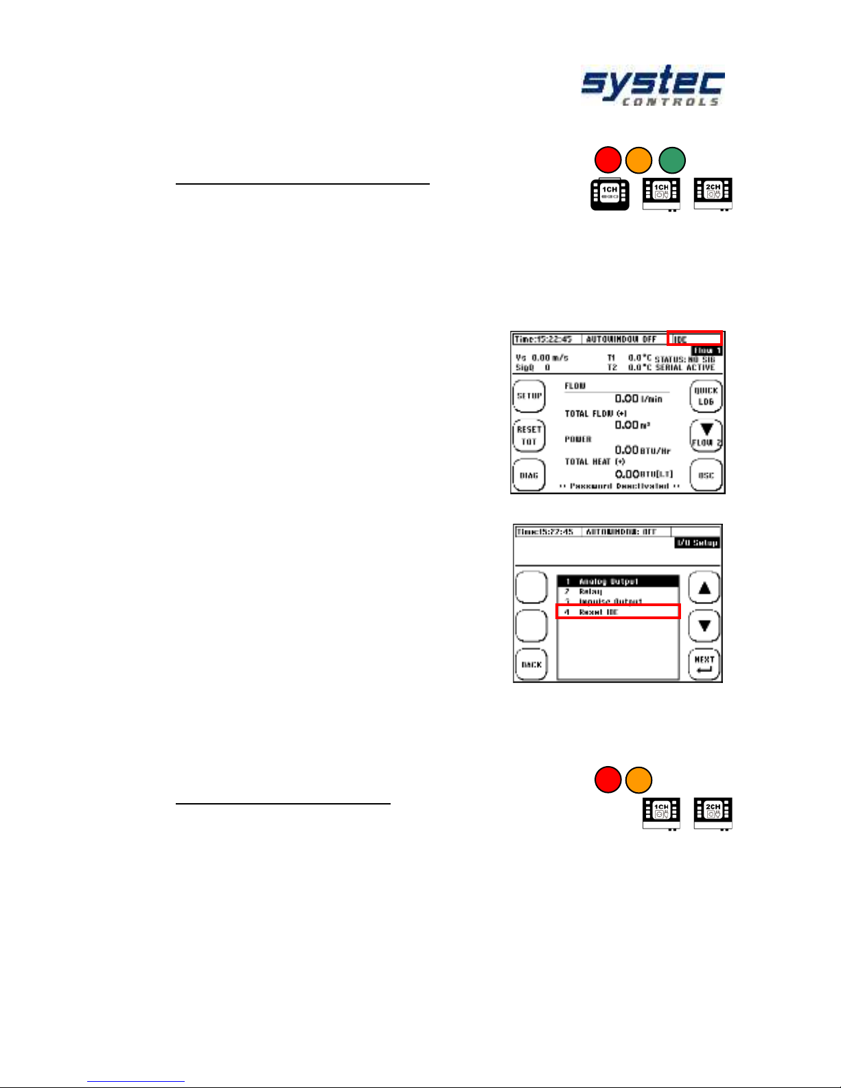
deltawaveC-F/P
Manual
61 systec Controls Mess- und Regeltechnik GmbH
11.5.4 Impulse-Overflow-Error; IOE
Occasionally, limiting cases can occur when using the pulse output: The value of
the selected pulse output parameter exceeds for a short time the maximum
pulse number that can be emitted per second. In this case the supernumerary
pulses will be deposited in the internal pulse buffer of the device and emitted as
soon as possible.
If the number of supernumerary pulses is bigger
than the maximum size of the impulse buffer (max.
4096 impulses can be buffered), the impulse output
will be deactivated and the error report pulse
Overflow Error (IOE) will be displayed in the right
column of the window header.
As soon as the IOE error appears, no pulses will
be output or buffered. An IOE is an indicator that
another pulse weight must be selected to make
sure the pulse buffer will not be in overflow again.
The digital display of the transmitter (volume, heat
quantity) is not affected by a pulse overflow. The
summed amounts are also displayed correctly in
the case of an IOE.
A reactivation of the pulse output is possible by
resetting the "Reset IOE" error via the I/O settings.
11.6 Serial communication, Modbus & Logger
11.6.1 Serial data transmission
With the serial data transfer, the digital transmission of the measured data via
RS232 / RS485 can be started in ASCII coding. The data is transmitted as a serial
digital data stream with a fixed frame consisting of a start bit, five to a maximum of
nine data bits, an optional parity bit for detecting transmission errors and a stop bit.
This form of data transmission is only available for deltawaveC-F.
Page 62

deltawaveC-F/P
Manual
62 systec Controls Mess- und Regeltechnik GmbH
Navigation in the User-Interface:
From the main measurement window "Flow 1":
select „SETUP“ then „COMPL SETUP“ then
„Serial/Modbus/Logger“ then „Serial Interface
Setup“
In this menu window, you can edit or view the basic
parameters of the data transmission.
Designation
Reset-Value
Other features
Serial COM:
Activation of data transmission
INACTIVE
ACTIVE
Baud rate:
Data bits per second
9600
19200, 38400, 56000,
57600, 115200
Parity Mode:
Error detection
NONE
ODD, EVEN
Data Bits:
Number of data bits.
8
not editable
Stop Bits:
Number of stop bits.
1
not editable
Log Interval:
Specifies the interval (time)
between two consecutive records.
00:00:01
Format: hh:mm:ss
hh… hours (00-23)
mm…minutes (00-59)
ss…seconds (00-59)
Reset:
Resets the serial interface to
factory settings.
NO
YES
After activation, the following data is transmitted semicolon-separated:
Pos.
Designation
Format
Pos.
Designation
Format
1
Date
JJJJ.MM.TT
7
Heat output
2 DS
2
time stamp
hh:mm:ss
8
Heat quantity
2 DS
3
Flow
2 DS
9
Temperature T1
1 DS
4
Flow rate
2 DS
10
Temperature T2
1 DS
5
Sound speed
2 DS
11
Diff.-Temp. T2-T1
1 DS
6
Totalizer flow
0 DS
12
Signal status
Text
13
Signal quality
0…100
To test the data transfer you can use the Windows own communication
program Hyper terminal. If your PC does not have a serial interface, you
can access a commercially available USB to RS232 adapter.
Page 63

deltawaveC-F/P
Manual
63 systec Controls Mess- und Regeltechnik GmbH
11.6.2 Modbus
The deltawaveC-F supports the digital transmission of the measured data via
Modbus protocol (master / slave architecture). RTU and ASCII Modbus are
supported via RS485. This form of data transmission is only available for
deltawaveC-F.
From the main measurement window "Flow 1":
select „SETUP“ then „COMPL SETUP“ then
„Serial/Modbus/Logger“ then „Modbus Setup“
In this menu window, you can edit or view the basic
parameters of the data transmission.
Designation
Reset-Value
Other features
Serial COM:
Activation of data transmission
INACTIVE
ACTIVE
Slave Address:
Of deltawaveC-F
1
1… 247
Operating mode:
ASCII
RTU
Baud rate:
Data bits per second
9600
19200, 38400, 56000,
57600, 115200
Parity Mode:
Error detection
NONE
ODD, EVEN
Data Bits:
Number of data bits.
8
not editable
Stop Bits:
Number of stop bits.
1
not editable
Reset:
Resets the serial interface to
factory settings.
NO
YES
Modbus Endian:
Byte sequence
BIG
ENDIAN
LITTLE
ENDIAN
The register overview can be found in the appendix. For additional
information, please contact systec Controls
Page 64

deltawaveC-F/P
Manual
64 systec Controls Mess- und Regeltechnik GmbH
11.6.3 The Data Logger
Logging of data is the time-controlled recording (storage) of measured value data
on the device internal memory.
With the deltawaveC-P, the data logger is freely available and
included as standard.
With deltawaveC-F (1CH) the data logger can be ordered as an
option. From firmware version 1.33.x (March 2016), the data
logger is included and can be unlocked (if required). An update of
the firmware to enable the data logger is enabled at any time.
Please contact us if you are interested in a vacancy.
With the deltawaveC-F (2CH) no data logger is currently available.
This feature will be available with new hardware from the middle of
2017 and can then be enabled as with the deltawaveC-F (1CH)
11.6.3.1 Activation of the data logger function:
The activation of the data logger is bound to a password. If you want to activate a
data logger that is not activated ex works, please proceed as follows:
1. In the main menu navigate to sub menu “6 Serial/Modbus/Logger“.
2. In the sub menu select menu item “3 Data logger“.
USB port is in the cable compartment. It can be reached by removing the cover on
the cable space.
4. Having connected deltawaveC-F to your computer, the device will be recognized
as mass storage device.
5. Now copy the file password.txt from the deltawaveC-F transmitter to your
computer.
6. Please send the file password.txt to systec or open the file password.txt with a
text editor and send the twelve-digit code to systec.
7. Subsequently you will receive a four-digit code for the activation which you enter
as a password. Afterwards, the data logger function is permanently activated, even
if you install a new firmware version on your measuring transducer.
Page 65

deltawaveC-F/P
Manual
65 systec Controls Mess- und Regeltechnik GmbH
11.6.3.2 Administration and structure of log data
The current hardware state (4GB SD memory) allows the recording of data up to
one year (with a 10 s interval 10 years) when recording in a secondary interval.
The speed of the USB data transmission is limited by the maintenance of the
measurement performance and is correspondingly slow. When exporting large
amounts of data, the recommendation is to remove the SD card and to exchange
the data directly via the corresponding slot on the PC.
Deleting log files can only be done via the USB connection to the PC. We
recommend copying the data to an external storage medium before editing or
visualizing data.
In the event of a power failure (for example, an empty battery at deltawaveC-P), the
data is not lost. As soon as the device is powered up again, the data recording
continues automatically (except the predefined duration of data recording has
already been exceeded).
Structure of the Log-File
Format
"*.csv"; Text separated by semicolon
Processing by text editors or spreadsheet programs (e.g., Microsoft Excel)
Headlines
Details of time control
Relevant details of the parameterization
Measurement
data
Date, time, volume flow, flow rate, sound velocity, volume totalizer, heat
output, heat dissipation titer, T1 [° C], T2 [° C], T2-T1 [° C], battery status,
signal quality, status
The measured values between two recording intervals are not averaged.
The current measurement value is always recorded at the respective time.
11.6.3.3 Starting a time-controlled data record
From the main measurement window "Flow 1":
select „SETUP“ then „COMPL SETUP“ then
„Serial/Modbus/Logger“ then choose
„Data Logger“
„Serial/Modbus/Logger““Data Logger“
Page 66

deltawaveC-F/P
Manual
66 systec Controls Mess- und Regeltechnik GmbH
Edit the file name:
- Use the arrow keys to select characters
corresponding to the PAR file name (up to 5
characters).
- Press "ENTER" to confirm the selection of a
character
- Press "DEL" to clear the last character.
- Exit by navigating to "END" and confirming with
"ENTER"
The name you have chosen (e.g. "12ABC") is provided with a 3-digit
number (initial filename: "12ABC000.txt"). A maximum of 65536 lines are
written per file. Then a new file is created and the number is incremented
by one ("12ABC001.txt").
Edit the time control
- Use the arrow keys to navigate
- Change the values with the (+) and (-)
buttons
- Press "ENTER" to confirm the edited
values
- With "ESC" return to the editing of the file
name
Example: It should every 60 seconds record data’s between 25.05.2012, 3 pm and
26.05.2012, 14 pm is.
1. Enter 25.05.2012 as start date
2. Enter the start time at 3 pm
3. Enter 001: 01: 00: 00 as the duration
4. Enter the interval 00:01:00
Note that the timer recording is coupled to the system time of
deltawaveC-F/P. If the system time or the system date is not set correctly,
this directly affects your parameterized data recording!
System time is also reset during a system reset.
The beginning of the data logging should always be in the future in relation
to the current system time of deltawaveC-F/P. Otherwise, the data logging
will not start.
Start 3 pm
Stop 4 pm
25.05.2012
26.05.2012
27.05.2012
Time range of data logging
Page 67

deltawaveC-F/P
Manual
67 systec Controls Mess- und Regeltechnik GmbH
11.6.3.4 Cancelling a time-controlled data record
If the logger is active and records data according to
the parameterization, this is indicated in the header
line: "LOG ACTIVE". With the deltawaveC-F, serial
communication and Modbus have priority and can
block the display.
If you plan to stop the scheduled recording, please
navigate as follows:
From the main measurement window "Flow 1":
select „SETUP“ then „COMPL SETUP“ then
„Serial/Modbus/Logger“ then choose
„Data Logger“
„Serial/Modbus/Logger““Data Logger“
To cancel the data recording, press "Yes"
If the recording is terminated prematurely, the data recorded until then are
retained on the SD card. Data is recorded up to the time of the exit.
11.6.3.5 Quick-Logger
The Quick-Logger function is only available for
deltawaveC-P.
It allows a quick start of the data recording with
standard settings:
The predefined file name oriented is made up of the
current system time and the number appendix (Z):
"hhmmsZZZ.txt"
(E.g. For 14:59:24 hrs: "14592000.txt"
Duration: endless
Interval: 10s
Activation: Press the "QUICK LOG" button for 3-4
seconds
Press and hold the button for several seconds to prevent accidental
starting. If the Quick Logger is active, "QLOGGER ON" is displayed in the
communication status.
Page 68
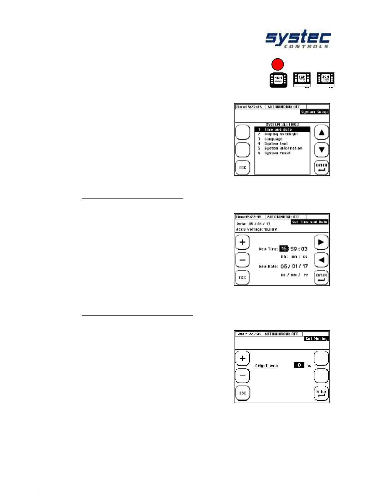
deltawaveC-F/P
Manual
68 systec Controls Mess- und Regeltechnik GmbH
11.7 Systems Settings
Navigation in the User-Interface:
From the main measurement window "Flow 1":
select „SETUP“ then „COMPL SETUP“ then
„System Setup “
The available submenus are shown on the right.
11.7.1 Editing the time and date
Navigation in the User-Interface:
From the main measurement window "Flow 1":
select „SETUP“ then „COMPL SETUP“ then
„System Setup “ „Time and date“
►◄: Navigation / Selection
+/-: Change of value
ESC/ENTER: Cancel / Confirm
Enter the current time (hh:mm:ss) and date
(DD/MM /YY) and confirm.
11.7.2 Changing the indicator light
Navigation in the User-Interface:
From the main measurement window "Flow 1":
select „SETUP“ then „COMPL SETUP“ then
„System Setup “ „Display backlight“
►◄: Navigation / Selection
+/-: Change of value
ESC/ENTER: Cancel / Confirm
Set the display brightness and confirm.
Page 69

deltawaveC-F/P
Manual
69 systec Controls Mess- und Regeltechnik GmbH
11.7.3 Changing the menu language
Navigation in the User-Interface:
From the main measurement window "Flow 1":
select „SETUP“ then „COMPL SETUP“ then
„System Setup “ „Language“
►◄: Navigation / Selection
ESC/ENTER: Cancel / Confirm
Select a language and confirm.
Use the language setting to change the language in the menus. The
language of the multifunction keys remains largely unchanged.
11.7.4 System test
Navigation in the User-Interface:
From the main measurement window "Flow 1":
select „SETUP“ then „COMPL SETUP“ then
„System Setup “ „System test“
▲▼: Navigation /Selection
ESC/ENTER: Cancel / Change of function
MUS: Switch to system test 2
The System Test 1 window allows you to directly
test the deltawaveC F / P outputs.
Description
Change with
confirmation (ENTER)
Action on activation
Relay
ON/OFF
Open/close the relay
Power Activate
Start/Stop
Outputs the parameterized current in
mA at the selected analogue output.
Pulse [50 Hz]
Start/Stop
Starts pulse output at 50 Hz.
The System Test 2 window allows you to indirectly
test the deltawaveC-F/P outputs by specifying a
flow rate. Parameterize a measuring point and
simulate a flow:
▲▼: Navigation / Selection
+/-: Change of value
ESC/ENTER: Cancel / Confirm
Page 70

deltawaveC-F/P
Manual
70 systec Controls Mess- und Regeltechnik GmbH
11.7.5 System information
Navigation in the User-Interface:
From the main measurement window "Flow 1":
select „SETUP“ then „COMPL SETUP“ then
„System Setup “ „System test“ “MUS“
This window can be used to check the system's
hardware and software.
CTRL Firmware
Firmware version of the user interface (CTRL Board)
CTRL Hardware
Hardware version (CTRL Board)
CTRL Flash2
Size of the Flash Memory 2 (CTRL Board)
MUS Firmware
Firmware version of the MUS Board
MUS Release Date
Release date of the MUS firmware
MUS Channels
Number of MUS channels: 1, 2
Device
portable, fix
Languages:
Integrated voice pack of the CTRL firmware
Units
unit system
Compensation Mode
Internal, external (integrated compensation)
11.7.6 System Reset
From the main measurement window "Flow 1":
select „SETUP“ then „COMPL SETUP“ then
„System Setup “„System reset“
The system reset function resets all parameters to
factory settings. If you receive a device with
unknown history or if the device shows
malfunctions, it is possibility to overwrite invalid
settings.
All settings are overwritten by a system reset, both the parameterization of
the measuring point, as well as the totalizer and the system time.
Page 71

deltawaveC-F/P
Manual
71 systec Controls Mess- und Regeltechnik GmbH
11.8 Unit selection
Navigation in the User-Interface:
From the main measurement window "Flow
1": select „SETUP“ then „COMPL SETUP“
“System Setup”
Choose the variable of which you want to
change the unit!
Physical size
Units supported by deltawaveC-F/P
Flow
m³/s; m³/min; m³/h; l/s; l/min; l/h; gal/s; gal/min;
gal/h; ft³/s; ft³min; ft³/h
Total Flow
m³; l; gal; ft³
Power
MW; kW; W; BTU/Hr; J/Hr
Heat
MWh; kWh; Wh; BTU/Hr(i.t); J
Fluid velocity
m/s; ft/s
Pipe dimensions
mm; inch
The unit "gal" is the US-American gallon.
Page 72

deltawaveC-F/P
Manual
72 systec Controls Mess- und Regeltechnik GmbH
11.9 Calibration
From the main measurement window "Flow 1":
select „SETUP“ then „COMPL SETUP“
„Calibration “
Select the desired calibration option from the
calibration menu.
11.9.1 Flow-Offset
Select in the calibration menu „Flow“.
Enter the desired offset correction
Check the flow at 2-3 relevant flow rates to check
whether the percentage correction is permissible.
The offset remains stored in the device until it is
overwritten by a new value.
11.9.2 Matching the Pt100
Select in calibration „PT100 T2-T1“
„Read OFFSET“:
Automatic calculation of the offset (T2-T1)
„RESET OFFSET“:
Resets the current offset to zero.
"YES": Confirmation of the calculated offset
"NO": Abort.
11.9.3 Pt100 Offset
In the calibration menu, select "Offset T1 / T2"
Now enter the actual temperature for T1 (default
value). Attention! The default value is an absolute
temperature and no offset with respect to the
displayed temperature, press "RESET" to clear the
default value. The Pt100 shows again the
temperature without correction.
Page 73

deltawaveC-F/P
Manual
73 systec Controls Mess- und Regeltechnik GmbH
11.9.4 Calibration of analogue outputs
The calibration of the analogue outputs is only possible for CTRL 2.0 or
higher (see System Information). From this hardware version the
deltawaveC-F/P is able to output the current in an extended range
(NAMUR NE 43).
The calibration of the analogue outputs is based on
a 2-point calibration.
Procedure:
1) Before coefficients for the correction of the
analogue outputs can be calculated, it is necessary
to measure the current currents for the present
values 4 and 20 mA at the respective outputs with
an admissible current measuring device. Use the
System test 1 window. (see 11.7.4).
2) Now change to the calibration menu and select
"Analog output".
3) Select the analogue output to be calibrated.
4) Enter the measured reference value for 4 mA
and confirm.
5) Enter the measured reference value for 20 mA
and confirm.
The correction coefficients are now calculated
automatically and stored in the system.
11.9.5 Parameterization of a flow velocity characteristic
In the "Flow Correction" submenu of the calibration
menu, you can view the points of a configurable
characteristic. Between the individual points is
linearly interpolated.
Characteristics can only be created for individual
measuring points and enable accurate
measurements even beyond the recommended
inlet and outlet distances.
Delete ALL:
Set all points to zero
Delete:
Set a single point to zero
▲▼:
Navigation / Selection
Next:
In the window for editing the points
Page 74

deltawaveC-F/P
Manual
74 systec Controls Mess- und Regeltechnik GmbH
After a point has been selected, the flow velocity (in
m / s) and the corresponding correction value (in%)
can be entered.
Example: At +0.15 m/s a deviation of + 0.8% was
determined. The corresponding correction point is
(+0.15; -0.8)
►◄:
Navigation / Selection
+/-:
Changing value
ESC:
Return to overview
ENTER:
Confirm of the edited values
As soon as a point pair [x=v(m/s); Y=correction(%)], the correction is valid and the
interpolation coefficients are internally recalculated.
Standard Rules:
Example: Parameterization of 3 points (see figure
on the right: P1, P2, P3).
From the point with the highest or lowest flow
rate. The correction is set to zero.
If a point with a different sign is not
parameterized, the value is linearly interpolated
between zero m / s and the first point.
If a point with a different sign is parameterized,
this is linearly interpolated between this and the
lowest beyond zero.
The parameterization of the zero point (0; 0) is
not permitted,
Special rule 1: The parameterisation of a
correction ≠ 0% for 0 m s is permissible.
Example: Parameterization of the 3 standard points
(see illustration on the right: P2, P3, P4) and P1
(0.0; 0.8%).
Linear interpolation between P1 and P2
Special rule 2: The parameterization of a deviation
of 0% for ≠ 0 m / s.
Example: Parameterization of the 3 standard points
(see figure on the right: P1, P2, P3) and P4 (6.0;
0.0%)
Linear interpolation between P3 and P4
flow velocity in m/s
correction in %
flow velocity in m/s
correction in %
flow velocity in m/s
flow velocity in m/s
correction in %
correction in %
Page 75

deltawaveC-F/P
Manual
75 systec Controls Mess- und Regeltechnik GmbH
11.10 Miscellaneous Parameters
Navigation in the User-Interface:
From the main measurement window "Flow 1":
select „SETUP“ then „COMPL SETUP“
„Miscellaneous “
11.10.1 Damping & Burnout
Select in the menu Miscellaneous "Damping flow"
or "Damping Pt100"
The editing of the burnout parameter is only
possible for the flow parameter and can be found in
the "Damping flow" menu item.
Damping flow rate / Pt100:
Here you have the possibility to damp the signal
output (temporal length of the mean value filter).
The larger the damping, the slower deltawaveC-F/P
reacts to changes changing values. Typical
attenuations range from 5-60 seconds.
Burnout FLOW:
Low signal quality (SigQ <50, headline top left) causes the measurement to be
invalid and the measured values fall to zero. With the help of the memory function,
the last valid measured value (SigQ> 50) can be retained for the parameterized
duration (= memory).
This function can be used to eliminate temporary disturbances (for example
short-term gas input or temporary disturbances of the flow profile). In
practice, the use of this function is recommended for strongly fluctuating
SigQ values / flow measurement values.
Page 76

deltawaveC-F/P
Manual
76 systec Controls Mess- und Regeltechnik GmbH
11.10.2 Cut off Flow
Select in the menu Miscellaneous "Cut off Flow"
Absolute flow velocities smaller than the edited flow
threshold will be not considered (zero set).
Flow values which depending from the flow (flow
rate, heat quantity, and so on) are also affected by
this parameterization.
11.10.3 Zero
Select in the menu Miscellaneous "Zero"
Here you can set the zero point (see 8.5), delete
and enter (manually edit based on documented
values).
The zero point remains stored in the device until it
has been automatically overwritten by a new zero
offset or has been manually removed by "Delete
zero".
The zero point is automatically deleted when
relevant parameters (pipe, medium or transducer)
are edited again. Be careful, when you perform
measurements with different application data!
11.10.4 The totalizer (counters)
DeltawaveC-F/P has two quantity counters, one quantity counter for volume flow
and one quantity counter for heat quantity. Both counters can be parameterized
independently of each other in regard to their way of counting. The
parameterization of the totalizers allows implementation of various applications
considering the bidirectional flow rate. It is, for example, possible to consider only
volume flows in a flow direction (positive or negative counter).
Particularly when parameterizing the heat quantity totalizers, pay attention the
effects of the signs have to be pay attended:
(+) Volume flow x (+) Temperature difference = (+) Heat output,
(-) Volume flow x (-) Temperature difference = (+) Heat output,
(-) Volume flow x (+) Temperature difference = (-) Heat output.
Page 77

deltawaveC-F/P
Manual
77 systec Controls Mess- und Regeltechnik GmbH
Example 1: Both the positive and the negative flow on the pulse output should be
detected on an external counter. In this case, the volume counter should be
parameterized as an absolute counter (+/- sum). The directional detection (positive
or negative) can then be carried via the relay and the difference in the evaluation
unit can be calculated according to the detected change in the sign.
Example 2: Only the positive flow through the pulse output is to be detected by an
external counter. In this case, the volume counter should be parameterized as a
positive counter (+) (without directional detection via the relay).
The impulse output of the transmitter behaves in line with the
parameterization of the counting method of the respective counter.
Parameterization of the totalizers
Type of Counter
Example
1. Positive-Counter (+):
Volumes with a positive flow
direction are summed up.
A flow of 30 litres in the direction of flow and
10 litres. In summary 30 pulses will be given
out.
2. Negative-Counter (-):
Volumes with negative flow
direction are added up.
A flow of 30 litres in the direction of flow and
10 litres. In summary 10 pulses will be given
out.
3. Amount- Counter (+/- Sum.):
The amount of all volumes is added
up.
A flow of 30 litres in the direction of flow and
10 litres. In summary 40 pulses will be given
out.
4. Different- Counter (+/- Diff.):
It is the sum formed from all
volumes (considering the sign)
A flow of 30 litres in the direction of flow and
10 litres. In summary 20 pulses will be given
out.
Navigation in the User-Interface:
From the main measurement window "Flow
1": select „SETUP“ then „COMPL SETUP“
„Miscellaneous“ Select now „Totalizer Flow“
or „ Totalizer heat“.
Now, parameterize the pulse output according
to the requirements of the application as
described above.
Page 78

deltawaveC-F/P
Manual
78 systec Controls Mess- und Regeltechnik GmbH
11.10.5 Sensor distance
The accuracy of the measurement results depends essentially on the fact that the
actual sensor distance corresponds to the recommended sensor distance (see 8.4).
Despite all this, it may be necessary that the sensor assembly deviates from the
recommendation (lack of space, better signal quality, and so on). In this case, it is
imperative to inform the different, "real" sensor distance to the system.
Measure the actual distance between the sensors
(head-to-head, see 8.4).
Select in menu Miscellaneous "Sensor Distance"
►◄:
Navigation / Selection
+/-:
Change of value
ESC:
Return to overview
ENTER:
Confirm the edited value
Enter the distance (in mm) and confirm.
Page 79

deltawaveC-F/P
Manual
79 systec Controls Mess- und Regeltechnik GmbH
12 Additional information about the hardware
12.1 Hardware and Software Reset
The deltawaveC-F/P distinguishes between two types of reset: hardware and
software reset. The data on the device-internal SD card remain unaffected by a
reset.
1. The Hardware Reset:
The hardware reset is an ON / OFF reset. The device is rebooted, and passes
through a full initialization. The data and parameters in the internal flash memory
are retained.
The hardware reset is used when the device is no longer responding (system time
is stopped, no keyboard input is possible, and so on).
Section of deltawaveC-F Connector-board
Remove the cover over the cable
compartment and press the Reset button
shown above.
Section of deltawaveC-P backside
Use a pointed object to press the
button located behind the opening on
the back of the device.
2. The Software Reset
Triggering a "Software Reset":
1. Immediately on the start: "RESET SYS."
2. From the main measurement window "Flow
1": select „SETUP“ then „COMPL SETUP“
„System SETTING“ „System reset“
In the case of a software reset, all values in the
flash memory and in the RAM memory of the
deltawaveC-F/P will be set to zero. The system is
then reinitialized with the factory settings.
The software reset is applied when no or non-plausible values are
displayed in display fields.
All parameters are reset (date, time, totalizer values, pipe parameters,
etc.); Load a pre-stored parameter file or re-parameterize the transmitter.
Page 80

deltawaveC-F/P
Manual
80 systec Controls Mess- und Regeltechnik GmbH
12.2 Data export and import
If the transmitter is connected via USB to a PC (see chapter 5), the SD card is
recognized as an external data memory (as of Windows XP / MAC OS X.x) and
data can be exchanged.
The speed of the USB data transmission is limited by the maintenance of
the measurement performance and is correspondingly slow.
Tip: For optimal data exchange it is advisable to deactivate any digital data
record (serial communication, Modbus, Logger).
When exporting large amounts of data, it is recommended to remove the
SD card and to exchange the data directly via the corresponding slot on the
PC.
Deleting log files can only be done via the USB connection to the PC. We
recommend copying the data to an external storage medium before editing or
visualizing data.
In the event of a power failure (for example, an empty battery at deltawaveC-P), the
data’s are not lost. As soon as the device is powered up again, the data recording
continues automatically (except the predefined duration of data recording has
already been exceeded).
For mass storage> 2GB the detection can take some time. Please wait a
minute.
Page 81

deltawaveC-F/P
Manual
81 systec Controls Mess- und Regeltechnik GmbH
12.3 Parameterization of the deltawaveC-F
pulse output hardware
For the output of the pulses the IC-DX of IC House listed below is used in the
deltawaveC-F.
The diagram below shows the layout of the pulse output. The pulse outputs are
indicated by a "white" colour map.
Layout:
1+
External source 8 … 30V
1S
Signal output
1 -
Ground
deltawaveC-F has implemented two digital outputs. The second digital
output (IMP 2) can only be used together with a two channel version.
The deltawaveC-F supplies three different operation modes:
- NPN (LOW SIDE)
- PNP (HIGH SIDE)
- PUSH PULL
Digital Out Config 1 (upper switch)
Digital Out Config 2 (lower switch):
To configure the operation mode of the
digital output, 6 DIP switches are available
for each digital output (SW2 for channel1
and SW3 for channel2).
The first DIP switches 1 to 5 will be used to
setup the operation modes (High Side,
LOW Side, Push Pull).
The DIP switch 6 is used to switch between
active (12V internal voltage supply) and
passive mode (external voltage supply 8 ...
30V).
Systec Controls recommends the PNP mode. This can be used in
conjunction with most 2 conductor pulse counters. Function test (voltmeter
without resistors) best with push-pull.
On
Off
On
Off
Operation mode
(PNP,NPN,Push Pull)
Internal power supply
aktive/passive
Page 82

deltawaveC-F/P
Manual
82 systec Controls Mess- und Regeltechnik GmbH
12.3.1 Operating mode 1: High Side (PNP-Switch)
Description:
The switch is closed without impulse. The connection to the power supply is
interrupted during pulse output.
High Side switch:
Resting state: signal on +
U-t diagram
Switch setting (PNP)
DIP switch configuration
1
OFF
2
ON 3 OFF
4
ON 5 OFF
6
OFF Ext. VCC; ON: int. 12V
Application:
According to the wiring example below, for this operating mode (1S) and (1-) must
be connected to the external pulse counter. (1S) is connected to the digital input
(DI) of your pulse counter, (1-) to the (GND) input of the external counter.
If the counter has a sufficiently high internal resistance, the resistor can be
dispensed with.
As a guideline value (test with voltmeter), we recommend 4.7 kΩ for the
pull DOWN resistor. In practice, the resistance value may deviate from the
recommended value depending on the internal resistance or maximum
permissible current.
8…30V external
1+
1S
1-
Dout
Din
Pull DOWN
resistor
VCC
GND
GND
External input /
counter
deltawaveC-F
U
UV
t
On
Off
SW2
+
-
Page 83

deltawaveC-F/P
Manual
83 systec Controls Mess- und Regeltechnik GmbH
12.3.2 Operating mode 2: LOW Side (NPN-Switch)
Description:
The switch is open without pulse. In the case of pulse output, the connection to the
voltage supply is closed.
Low Side switch:
Resting state: signal on -
U-t diagram
Switch settings (NPN)
DIP switch configuration
1
OFF
2
ON 3 OFF
4
OFF
5
ON 6 OFF Ext. VCC; ON: int. 12V
Application:
According to the wiring example below, for this operating mode (1S) and (1-) must
be connected to the external pulse counter. (1S) is connected to the digital input
(DI) of your pulse counter, (1-) to the (GND) input of the external counter.
The resistance is mandatory for NPN parameterization.
As a guideline (test with voltmeter) we recommend for the pull UP resistor
4.7 kOhm. In practice, the resistance value may deviate from the
recommended value depending on the internal resistance or maximum
permissible current.
8…30V external
1+
1S
1-
Dout
Din
Pull UP
resistor
VCC
GND
GND
External input /
counter
deltawaveC-F
On
Off
SW2
U
UV
t
+
-
Page 84

deltawaveC-F/P
Manual
84 systec Controls Mess- und Regeltechnik GmbH
12.3.3 Operation Mode Push-Pull
Description:
A Push Pull configuration will be a complementary transistor pair in the output stage
(n-channel and p-channel). One of the two transistors always blocks, while the other
one is open.
Advantage: This operating mode requires no pull-up or pull-down resistor
and has very short switching times. This makes it particularly suitable for
functional tests.
The IC used has a thermal protection circuit (shutdown: 151 ° C, release:
150 ° C). The output current is limited to 450 mA. Nevertheless, avoided
connecting the push-pull directly with GND or + VDC.
Push-Pull:
Resting state: signal on +
Transistor 1 closed
Transistor 2 open
Active state:
Transistor 1 open
Transistor 2 closed
U-t diagram
Switch settings (Push-Pull)
DIP switch configuration
1
ON
2
OFF
3
ON 4 OFF
5
OFF
6
OFF Ext. VCC; ON: int. 12V
8…30V external
1+
1S
1-
Dout
Din
VCC
GND
GND
External input /
counter
deltawaveC-F
U
UV
t
On
Off
SW2
Page 85

deltawaveC-F/P
Manual
85 systec Controls Mess- und Regeltechnik GmbH
12.4 RS232 / RS485 Interfaces
The firmware on your deltawaveC-F is already equipped with all necessary
functions for data output of the measured values via an RS232 / RS485 interface.
Each deltawaveC-F can be retrofitted with a serial interface card (option).
RS232 interfaces allow cable lengths up to approx. 20 m between deltawaveC-F
and evaluation unit. RS485 interfaces allow cable lengths up to several 100 m
between deltawaveC-F and evaluation unit. Additional, a Modbus communication
can be realized via the RS485 interface card.
The Modbus functionality of deltawaveC-F via RS485 interface is not
discussed in this manual. For additional information, please contact systec
Controls.
RS232 interface board:
The RS485 interface board is configurable for 2wire or 4-wire communication mode (Jumper).
Subsequent installation:
Disconnect your deltawaveC-F from the power supply. Just put the serial interface
board on the two free socket boards, that’s it.
jumper settings
2-wire mode
jumper settings
4-wire mode
Page 86

deltawaveC-F/P
Manual
86 systec Controls Mess- und Regeltechnik GmbH
Connecting the serial interface board with a receiver (e.g. a PC) exemplary
shown in case of a RS232 interface board:
To establish a connection between deltawaveC-F and a PC, please produce a
connection cable with the following plugs in case of a RS232 interface board:
Designation
Pin 9 Pol. Sub D
TX
Transmit Data
3
RX
Receive Data
2
GND
Ground
5
Several participants or the bridging of longer distances with the
corresponding load with interfering signals may require the application of
an appropriate termination.
SUB-D 9 pin
Solder side view
Page 87

deltawaveC-F/P
Manual
87 systec Controls Mess- und Regeltechnik GmbH
13 Tips and Tricks
13.1 Measuring mixed fluids
If liquids are present as a mixture, then in a first step it is necessary to know the
mixing ratio.
To draw conclusions on the actual values of a liquid mixture
The application of complex calculation models is normally required. In practice, the
approach described below helps to achieve a reliable measurement result in
pragmatic terms in most cases.
The following is an example of the mixture: 10% glycol; 90% water (20 ° C). To
configure the fluid mixture, proceed as follows:
A.) Material data
The substance data of the individual components are required. Material data for
relevant media are stored in the deltawaveC-F / P database and can be found in the
parameter overview or the substance data tables in the appendix of this manual.
The following data are required for the correct determination of the flow velocity:
- Sound velocity
- Kinematic viscosity
The following data are also required for the correct determination of the heat
quantity:
- Heat capacity
- Density of the medium
For the above example, the following material data are obtained for 20°C.:
Water 100%
Glycol 100%
Vs [m/s]
1486
1666
Kinematic Viscosity [E-6 m²/s]
1,003
21,11
Density [kg/m³]
998,20
1110,00
heat capacity [kJ/kgK]
4,182
2,400
B) Linear approximation
Multiply the respective component fraction (mass fraction, volume fraction material
fraction) with the component property, and add both.
Vs (mixture) = ∑(Vs
Components
* Quantity
Components
)
Vs (mixture) = (1486 m/s * 0,9) + (1666m/s * 0,1)
Vs (mixture) = 1504 m/s
Page 88

deltawaveC-F/P
Manual
88 systec Controls Mess- und Regeltechnik GmbH
According to the example, the following material data are obtained for the mixture at
20°C:
Water 90%, Glycol 10%
Vs [m/s]
1504
Kinematic Viscosity [E-6 m²/s]
3,0137
Density [kg/m³]
1009,38
heat capacity [kJ/kgK]
4,0038
C) Parameterization of the medium
Afterwards please navigate from the main menu again to the menu option
“Parameter medium”. Select users input now and enter the values you have
calculated as user-defined values.
If the characteristics of the specific substance are not in the manual or the
database of the device, data sheets of the producer of the fluid can give
you information on its parameters.
Also useful in the search for substance data are specialized search engines
(http://www.wolframalpha.com/).
As the parameter viscosity of a fluid is very often not given. In this case, the
value of density and dynamic viscosity can be calculated. Be sure to enter
the values on the units.
Helpful converter: http://www.cactus2000.de/de/unit/massvis.shtml
13.2 Measuring unknown fluids
In practical applications it is quite possible that there is no information regarding
sound velocity (or other material data) or composition for a specific fluid. As an
example, the food industry (various beverages, for example apple juice) is
mentioned here.
In order to determine the flow rate in the tube and thus the volume flow in the tube,
the sound velocity of the medium is primarily important. The kinematic viscosity is
necessary for correct Reynolds compensation (see chapter 4). The density and
heat capacity are only important for the determination of heat output or heat
quantity. To stay with our example: In the case of apple juice it is rarely necessary
to carry out a heat quantity measurement.
Furthermore, it is sufficient for watery solutions to assume the values of water in a
first approximation. For hydrocarbons, the values of oil or gasoline, depending on
the application.
Example: You do not know the exact composition of your medium, but you can
assume that it is an aqueous solution.
Page 89

deltawaveC-F/P
Manual
89 systec Controls Mess- und Regeltechnik GmbH
Proceed as follows:
1. Parameterize your deltawaveC-F/P according to the application (quick setup,
pipe dimensions, and so on).
2. As soon as you select the liquid, select the medium which is the most similar
to the medium to be measured from the deltawaveC-F / P database. In this
case water (20 ° C).
3. Now install the ultrasonic transducers according to the sensor distance output.
4. Now change to the measurement
window 1. The sound velocity of the
medium is displayed at the top left.
5. Now run the Quick setup again. When
selecting the medium, select user input
and edit the sound velocity according
to the value displayed in measurement
window 1 (leave all other values).
6. Complete the Quick setup now. In the setup window, you will now see a
sensor distance corresponding to the parameterization.
7. If a different sensor distance is recommended, change the installation of the
ultrasonic transducers accordingly
8. Start again from point 4. Repeat the procedure until the sensor distance output
from deltawaveC-F / P no longer changes.
In rare cases it might happen, that the measuring inaccuracy is not
satisfactory even if you have followed the procedure above.
In this case, we recommend compensation using an offset correction.
Reset the Totalizer value ("RESET TOT"), start the flow and catch the flow
of the fluid in a container. Determine the volume (directly or via mass
determination and density) and compare the value with the deltawaveC-F/P
display.
Now parameterize the corresponding compensation value:
From the measuring window 1 outgoing Complete setup Calibration
Flow offset. Now enter the percentage of deviance between the
reference quantity and the measured quantity.
Page 90

deltawaveC-F/P
Manual
90 systec Controls Mess- und Regeltechnik GmbH
14 Troubleshooting
You have parameterized a measuring point, the ultrasonic transducers are mounted
and do not get any plausible results or the flow zero. Or you can get meaningful
results in the display of the deltawaveC-F/P, but have difficulties on transmitting the
results analogously or digitally.
This chapter provides a help guidance procedure for successful support:
A) Checklist: Use the checklist (see 14.6) for troubleshooting and work through
this point by point. If this is not successful, continue with B.
Print out the checklist and work through it step by step. This helps you keep
a cool head during a difficult application and systematically limit the error.
B) Preparation for the support:
1) An extensive evaluation of the device parameterization is essential for
successful support. To ensure this, the simplest and safest method is to
save the current parameter set (see chapter 11) and export the file
(alternatively, you can take pictures of all windows in the parameter
overview).
2) If you do not receive plausible flow data, an image of the current signal
window should also be sent to the support. Navigate to the oscilloscope
window and perform an A-Scan export (see chapter14.1). Copy the WAV
file via USB (alternatively, you can make a photo of the current signal
window).
3) In addition, it is possible to take pictures of the ultrasonic transducers
installed on the tube. If you are experiencing problems with the analogue
or digital signal transmission, you also have a picture of the cable
connection space or the wiring.
C) Contact systec Controls
089 / 809 06 0 and info@systec-controls.de
And submit the data to the assigned support (PAR file, WAV file and
photos of the converter installation)
If you do not have the option to send the data electronically (email), please
provide the following information: pipe material, pipe diameter, wall
thickness, medium, medium temperature, type / length of the inlet sections,
sensor type.
Page 91

deltawaveC-F/P
Manual
91 systec Controls Mess- und Regeltechnik GmbH
14.1 The Oscilloscope Window
The oscilloscope (OSC) window can be accessed
via the OSC button in the measurement windows or
in the diagnostics window.
The OSC window provides the signal analysis, the
most powerful diagnostic tool. The currently
evaluated signal window is displayed. In particular,
the signal shape, the signal sharpness, the signalto-noise ratio (SNR) and the type of noise are of
particular interest.
◄/◄◄
Slow / fast decrease of the deceleration or on the time axis to the left
►/►►
Slow / fast increase the delay or move to the right on the time axis
A.WIN
Y/N
Auto window: Turn the function on / off
MEAS
Return to the measurement window
From the standard header differing display:
The deltawaveC-F/P allows storing current signals (A-Scan) as a WAV file on the
SD card. The A-Scan export can only be carried out in the OSC window:
1) Press and hold the backlight button for about 5 seconds.
2) The OSZ screen freezes and it appears at the bottom of the screen: "AScan Export in progress". The A-scan takes approximately 2-3 seconds.
After completion, the following appears: "A-Scan Exported to SD-card".
3) A corresponding "* .wav" file has now been stored on the device-internal
SD card. The file drawing is generated automatically based on the current
system time. For the system time (hh: mm: ss) and date (YYYY.MM.TT),
the name "TThhmmss.wav" is given.
4) Connect your deltawaveC-F / P to a PC (USB cable) and copy the desired
WAV file.
Display
Explanation
Values
Flow
Flow rate
Power
Heat output
T1 / T2
Temperature values of the Pt100
Delay
Start value of the displayed signal window in μs
Gain
Value of the signal gain for the displayed signal
Page 92

deltawaveC-F/P
Manual
92 systec Controls Mess- und Regeltechnik GmbH
14.2 Signal analysis
The deltawaveC-F/P provides powerful diagnostics capabilities that allow the skilled
user to make reliable measurements even in difficult applications. The oscilloscope
window allows you to quickly assess the quality of your signals. This is especially
helpful if you do not get any, or doubtful results. Two signal parameters are
particularly important for a good measurement: the signal-to-noise ratio and the
signal sharpness.
In order to fully exploit the possibilities of signal analysis, the understanding of wave
propagation and signal processing is helpful.
The diagram schematically illustrates
various ways that an ultrasound signal
can take in the pipeline.
The refraction and reflection at the
phase boundary surfaces is determined
by the combination of the material
properties.
The UP transducer (upstream transducer) emits an ultrasonic signal downstream.
This signal splits up and is transmitted directly in the pipeline (pipe wall signal) as
well as reflected in the medium (Z-mounting signal, V-montage signal, W-mounting
signal).
Depending on the mounting position (Z, V or W mounting) and the signal
propagation time, the DOWN transducer (downstream transducer) receives the
most diverse signals in varying time windows.
After the reception signal is recorded, the transmitter and receiver functions are
exchanged and the transmission-reception cycle is repeated. This time, however,
the send signal is sent upstream.
The signal propagation time is the
time that a signal spends on the signal
path associated with it. It depends on
the path length and sound velocity in
the media being traversed.
After a time “tp” can see the signal
that has travelled directly to the pipe
wall along.
This is usually the first signal on the time axis at the V- or W-position because it has
the shortest path length and the sound velocity of the tube wall material is generally
higher than that of the liquid. Then, at time t1v, the V-mount signal comes (simple
reflection) and after approximately twice the time, t1w the W signal (double
reflection).
In the case of highly sound conducting piping material (metals) and small pipelines,
the piping signal has high amplitude, similar to that of the V-mounting signal. In the
case of damping pipeline materials (plastics), the pipe wall signal is often
tp
t1v
t1w
time
Amplitude
Send
signal
Pipe Signal
V
-
Mode
-
Signal
W
-
Mode
-
Signal
tp
t1v
t1w
time
Amplitude
Send
signal
Pipe Signal
V
-
Mode
-
Signal
W
-
Mode
-
Signal
UP-Transd. V-Mode W-Mode
Desired
Signal
Pipe Signal
V
-
Mode
Signal
W
-
Mode
-
Signal
Z-Mode
Z
-
Mode
-
Signal
UP-Transd. V-Mode W-Mode
Desired
Signal
Pipe Signal
V
-
Mode
Signal
W
-
Mode
-
Signal
Z-Mode
Z
-
Mode
-
Signal
UP-Transd. V-Mode W-Mode
Desired
Signal
Pipe Signal
V
-
Mode
Signal
W
-
Mode
-
Signal
Z-Mode
Z
-
Mode
-
Signal
Page 93

deltawaveC-F/P
Manual
93 systec Controls Mess- und Regeltechnik GmbH
significantly weaker. The V-mount signal is usually much stronger (higher
amplitude) than the W-mount signal. The W signal returns approximately twice the
path in the flowing medium. Thus, it is exposed to the signal attenuation
phenomena (absorption and scattering) over a longer distance in the medium.
In the case of the Z-mount, a
different image is obtained.
Here, in addition to the send
signal, only the Z signal (at t1z)
can be seen itself.
In the oscilloscope window
itself, only a small time interval
is displayed. The position of this
measurement window is defined
by the delay. The length is
determined by the number of
recorded measuring points (no.
Of samples) and the measuring
rate (fADC).
In the oscilloscope window, you usually only see the signal required for the
evaluation (for example, the V-mount signal).
14.2.1 Signal-to-noise ratio (SNR)
The signal-to-noise ratio (SNR) is an indication of the influence of interference
signals on a defined useful signal. The more clearly the signal is detected, the more
stable the digital evaluation of the useful signal.
A similarly poor signal-to-noise ratio can be caused by various phenomena:
1) A bad acoustic signal (with low noise level)
2) A high level of acoustic interfering signals (scattering signal of particles or
bubbles)
3) A high level of electrical noise (EMC problems)
In any case, an improvement in the signal quality can be achieved either by an
improvement in the acoustic useful signal or by avoiding interference signals.
tp
t1z
time
Amplitude
Send Signal
tp
t1z
time
Amplitude
Send Signal
tp
t1v
t1w
time
Amplitude
Send
signal
Pipe Signal
V
-
Mode
-
Signal
W
-
Mode
-
Signal
tp
t1v
t1w
time
Amplitude
Send
signal
Pipe Signal
V
-
Mode
-
Signal
W
-
Mode
-
Signal
delay
time window
no. of samples
fADC
Page 94

deltawaveC-F/P
Manual
94 systec Controls Mess- und Regeltechnik GmbH
The following is a list of some measures for improving the useful signal quality:
Surface of pipe: Remove painting or rust
Coupling grease: Use sufficient coupling grease (Magnalube)
Alignment of transducers: Make sure that transducers are mounted as
suggested by deltawaveC-P. Please also make sure that centre of
transducers touches the pipe sufficiently (might be problem with very small
pipes). You can check the oscilloscope while mounting the transducers.
Make sure that transducers are not mounted e.g. on welding seams
Select another pipe position, e.g. A rising pipe (ensuring a fully filled pipe).
Make sure to provide sufficient straight run
Minimize the signal path (Z- instead of the V- or V- instead of the W-
mount)
Use a different transducer (lower frequency)
The following is a list of some measures to avoid interfering signals:
For the deltawaveC-F/P, ensure that the shield and core of the converter
cables are connected correctly (see 3.3).
Check whether your media is sufficiently vented and does not contain too
many solids.
Ensure that the sensor cable is sufficiently far from the power cables.
Especially keep the pump and frequency inverter apart.
Figure 23shows a signal with strong noise (unfavourable SNR). A clear noise can
be seen on the time axis before and after the signal.
Figure 23b shows signal examples with "good" SNR. On the time axis virtually no
more noise can be seen, the signal is ideally on the time axis.
a)
b)
Figure 23: Sample signals (oscilloscope window) with different SNR
Page 95

deltawaveC-F/P
Manual
95 systec Controls Mess- und Regeltechnik GmbH
14.2.2 Signal sharpness
The signals from deltawaveC-F / P are coded to reliably identify the ultrasonic
signals even in the case of very poor signal-to-noise ratios. For this purpose
deltawaveC-F / P uses phase shifts in the transmit signals. The more clearly these
phase shifts can be seen in the receive signal, the more stable your measurement
will be under unfavourable measuring conditions. Figure 24a shows a signal with
very high signal sharpness
One can clearly recognize approximately 5 oscillations with increasing amplitude
and then a reduction amplitude (phase shift) and then again increasing amplitude.
The reception signal clearly shows the coding of the transmission signal. This is not
the case for the signal in Figure 24b. The amplitude increase is initially very small
and only after the phase shift does a high amplitude modulation occur.
a)
b)
Figure 24: Sample signals concerning signal sharpness (oscilloscope window)
In addition to the general measures for improving the useful signal quality
(see 14.2.1), the following possibilities for improving the signal sharpness can be
checked:
Select an installation location with another pipe (other material, other
dimensions).
Try other signal encodings (see 14.3)
The highly developed signal evaluation of the deltawaveC-F/P also allows
for permissible measurement results even with very unfavourable signal
sharpness.
Nevertheless, the user should always try to ensure the best possible signal
of sharpness, since this reduces the scattering of the measured values in
case of additional disturbances.
Page 96

deltawaveC-F/P
Manual
96 systec Controls Mess- und Regeltechnik GmbH
14.2.3 Signal decoupling on small pipelines
In the case of small pipelines (<50mm), the
times between the signals are very short or
in the worst case the signals can even
overlap (with pipe signal, also with W
signal). The graphic on the right shows how
the different signals can appear in this case.
In the case of a signal overload, there are
different ways of doing so:
Use W-Mode rather than V-mode (first
counter-measure)
Use Z-Mode rather than V-mode (when
W-mode does not work)
Disable auto-window function and
manual positioning of the
measurement window
Alternative signal coding tests for a
narrower / sharper signal ("Barker5" or
"Pulse" instead of "Barker7")
Use a higher frequency converter to
obtain a narrower and sharper signal.
When using a 2MHz transducer instead of a
1MHz transducer, signals are only half as
long and thus easier to analyse (see right).
For manual positioning, you must always
check your settings using the measured
medium sound velocity. If this is too high or
too low (> 20%), you can assume that you
have the wrong signal in the measurement
window (for example V signal instead of W
signal or vice versa).
Figure 25: Signal superimposition for
small pipelines
Figure 26: Signal decoupling through
higher transducer frequency
The deltawaveC-F/P has very powerful signal unbundling algorithms.
These are applied when you enable the Auto-Window function.
Nonetheless, signal superimposition may occur in particular in the case of
very small pipelines and / or unsafe pipe dimensions. In this case, the user
can manually remove the signals in the oscilloscope window.
Page 97

deltawaveC-F/P
Manual
97 systec Controls Mess- und Regeltechnik GmbH
14.2.4 The Auto window function / AFC-Technology
The positioning of the ultrasonic transducers is essentially based on the basic data
of the parameterization. This also means that a variable sound velocity of the
medium flowing in the tube would have to bring about a permanent repositioning of
the ultrasonic transducers.
Practically speaking, this is relevant to:
1) Temperature variation: The sound velocity of a medium is temperaturedependent.
2) Medium change: Depending on the application it is possible that
alternating different liquids are passed through the same pipeline.
3) Changes in concentration: Depending on the application, it is possible that
concentration components will vary from the liquid component. This, albeit
to a small extent, is caused by changes in sound velocity.
The algorithms of deltawaveC-F / P take into account the currently evaluated sound
velocity for the calculation. This means that changes in the sound velocity as well
as the invariable position of the ultrasonic transducers are iteratively taken into
account in all subsequent calculations. This leads to a continuous correction of the
variable boundary conditions "fluid" and is referred to as AFC technology
(Automatic Fluid Control).
In general, it is not always useful to evaluate the total signal during ultrasonic
measurements (interference signals, high memory requirements, high signal
processing expenditure, and so on). The deltawaveC-F/P places a measuring
window according to the parameterization in which the useful signal is expected
(see 14.2). Only in this range is the signal recorded and evaluated.
All signals appearing in the measurement window are compared with the send
signal. The signal is accepted as valid and a corresponding evaluation is carried
out.
Variant properties of the liquid have not only effects on the calculations, but also on
the position of the useful signal (valid receive signal) within the measurement
window. A higher sound velocity means that the signal arrives earlier (shifting to the
left on the time axis) a lower sound velocity is the opposite.
If these effects were not taken into account, the signal might migrate out of the
evaluated measurement window in the event of a strong change in the liquid
properties (medium change, temperature or concentration changes).
Page 98

deltawaveC-F/P
Manual
98 systec Controls Mess- und Regeltechnik GmbH
The auto window function cyclically checks the
position of the useful signal in the measurement
window and adjusts the measurement window
position (if necessary, the adjustment of the delay
value) to the current conditions.
Optimal position of time
window:
Not optimal (BUT uncritical) position of time
window:
Critical (incorrect) position
of time window:
The Auto window function is activated and deactivated in the OSC window
(see 14.1). The Auto window function status is displayed as a general
header information.
An activated auto window function always tries to keep the measurement
windows at the position calculated by deltawaveC-F/P as the ideal position.
If you want to manually position the measurement window using the arrow
keys in the OSZ window, you must deactivate the auto window function.
Page 99

deltawaveC-F/P
Manual
99 systec Controls Mess- und Regeltechnik GmbH
14.3 The diagnosis window of the deltawaveC-F/P
Navigate to one of the measurement windows:
„DIAG“
The diagnose window gives an overview of all
relevant application and signal parameters. As well
relevant results of the signal processing are shown.
The function button above the OSC-button (mid
button on the right side) can be used to switch
between the available send signal codes.
Parameter
Description
Freq.
Central frequency of the send signal: 500kHz (XUDC05),
1000kHz (XUDC10), 2000kHz (XUDC20)
Mount type
V-, W- or Z-mode (see 8.4.2)
XDCR dist.
Mounting distance between the transducer front areas
Bar index
Whole index for the installation with mounting bar.
vS
Sound velocity of the medium
Gain
Current gain of the received signal (see 14.1)
SigQ
Percental amount of der prozentual of as valid recognitioned
signal pairs. Typical value might be in the range 75-100%.
dt ZERO
Currently parameterized value of the ZERO point calibration
(siehe 8.5)
F.-Offset
Shows the value currently parameterized for the flow offset (see
11.9.1).
Send Code
Encoding of the send signal. The send code can be changed
manually. Following codes are available: „Puls“, „Burst4“,
„Barker5“ and Barker7“.
For most of the applications it is not recommended to switch
from “Barker7“ (default setting) to any other send code. In some
cases (small pipes or unreasonable signal sharpness, see
14.2.2) it might be useful to test the “Barker5“ code.
Page 100

deltawaveC-F/P
Manual
100 systec Controls Mess- und Regeltechnik GmbH
14.4 Integrated sensor test function
The deltawaveC provides the option to test the operation of the ultrasonic
transducers in combination with the signal lines. For example: if you do not
measurement results from your actual application measurement you can test, your
ultrasonic transducers and signal lines are intact and the loss of measurement is
caused by the application itself.
Navigate to the oscilloscope screen:
1) Ensure that the AUTOWINDOW-function is
deactivated (see 14.1)
2) Reduce the delay to 0 µs via arrow
buttons. Now the output „SENSORTEST”
is shown, the flow will no longer be
determined anymore.
3) If not completed already connect the transducer and parameterize the
correct type (main menu transducer setup)
4) Put on one of the two transducers a little
acoustic coupling grease. Put both
ultrasonic transducers together as shown
in the picture to the right. Approximately
2/3 of the acoustic transmission surface
should overlap (Z-mode without pipe).
5) If both ultrasonic transducers, the signal lines and the electronics are intact
shortly after the beginning (NOT immediately at the start) of the
measurement window signal wavelets will appear which are transmitted
from one to the other transducer (see figures below).
F21 sensor test
F10 sensor test
F05 sensor test
 Loading...