

Page 1

deltawaveC
deltawaveC----FFFF 2CH
deltawaveCdeltawaveC
2CH
2CH 2CH
Quickstart
Quickstart
QuickstartQuickstart
V1.01
A
User Interface
User Interface
User InterfaceUser Interface
deltawaveC-F will be switched on automatically after supply voltage has been plugged on.
Activates / deactivates the background lighting
To navigate through the different menus please use the keys located on the left and right beside the
display.
Move cursor in specific direction
Confirm your settings
Back to previous menu
XYZ
Activates a certain function (depending on choosen menu)
Confirm your settings and moves to next menu
Increase of values
Decrease of values
No function
B
Set
Set----up your flow measu
up your flow measurrrrement in 5 steps
SetSet
up your flow measuup your flow measu
1. Choose suited mounting position for your transducers
2. Parameterize your flow transmitter
3. Mounting of ultrasonic transducers on your pipe
4. Set zero point (if possible)
5. Start your flow measurement
Pipe need to be filled completely for clamp-on measurement
ement in 5 steps
ement in 5 stepsement in 5 steps
C
Parameterization and mounting
Parameterization and mounting
Parameterization and mounting Parameterization and mounting
1. Switch on flow transmitter (automatically when plugging on supply voltage, see below)
2. Choose menu „quick setup“
3. Select measurment channel 1 or 2
4. Select diameter or circumference (depending on what figure you have) of your pipe
5. Put in value for diameter or circumference
6. Put in value for wall thickness of your pipe
7. Select pipe material
8. Select lining (if there is a lining)
9. Select type of ultrasonic transducer
Nr. 1 = XUC-FW-F21 DN10…..DN100
Nr. 2 = XUC-FW-F20 DN10…..DN100 (replaced by ultrasonic transducer model XUC-FW-F20 )
Nr. 3 = XUC-FW-F10 DN32…..DN400
Nr. 4 = XUC-FW-F05 DN200…DN6000
10. Select method of mounting. Standard is V-mounting.
Page 2
0 1 2 3 4
11. Mount ultrasonic transducers on a pipe
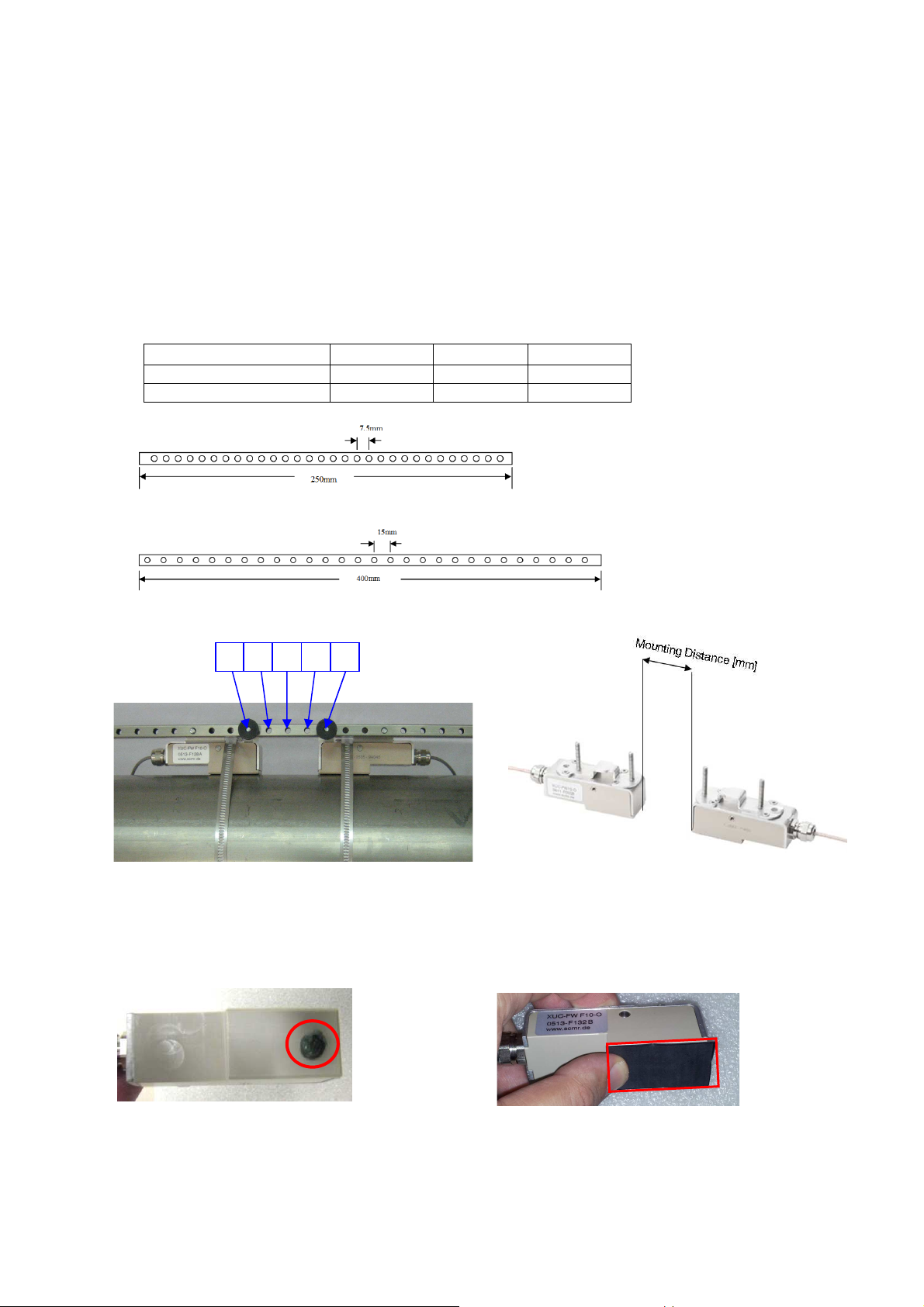
After parameterization the display is showing the required distance between the two transducers in
mm and also as Index-No. Index-No. means the number of holes to be used for mounting with the
spacer bar. The first hole after the first transducers is hole No. 1, the last hole is the hole where
second transducer is put into the spacer bar (threaded bar). Picture 3 shows an example for an index-
No. 4.
Together with deltawaveC-F unit itself you will get one pair US- transducers an a spacer bar
with matches together with the delivered US- transducers .
If you have ordered more deltawaveC-F units and US- transducers for different pipe diameters
it could be that you got spacer bars with different length (short or long). Pls. see in the chart below
which spacer bar could be operated together with the corresponding transducer model.
Spacer bar F10 F20 F21
Short (25 cm) X
Long (40 cm) X X
Picture 1 spacer bar short (length 250mm, grid hole distance 7,5mm)
Picture 2 spacer bar„long“ (length 400mm, grid hole distance 15mm)
Picture 3 Example for spacer bar with bar Index 4 means Picture 4 example for distance in mm without
3 holes spare between us- transducers (V or W mode)
Some acoustic coupling gel (app. size of a peanut, picture 5) or acoustic coupling foil has to be put at the part which
touches the pipe wall after installation (picture 6).
Picture 5 Using acoustic coupling gel Picture 6 Using acoustic coupling foil
(Magnalube)
Page 3

12. Chose best location for US- transducer installation.
If you install one pair of transducers on each pipe straight run should be 10x diameter (inlet) and 3x
diameter (outlet) in order to achieve best accuracy. If you install 2 pairs of transducers on the same
pipe it could be used to; increase accuracy, for redundant operation or to reduce effects of flow
inclination (see pictures 8 and 9). It is mandatory that both transducers are installed exactly shifted
about 180°.
When using horizontal pipe we recommend mounting the transducers at 10 o’clock or 2 o’clock
position to avoid any influence of gas bubbles / sedimentation might accumulated on top / on bottom
of pipe.
Pipe
Gas bubbles
Sedimentation
Picture 7 Example Mounted Transducers with spacer
bar and mounted at app. 9 o`clock
Picture 8 Example two transducer Picture 9 Example two transducer one
pairs on the same pipe to increase line. Second transducer pair lies exactly
accuracy or to reduce effects of 180° shifted to the first transducer pair
flow inclination or for redundant
operation.
13. The transducers are fixed to the pipe by using metal belts. The metal belts are tightened by using
tightener (picture in the middle). The length of the belts are designed for the biggest pipe size your
transducer can cover. Please feed the belt into the tightener as shown in picture on
the left. Proceed in the same way for PT100. PT 100 Nr. 2 must be installed on the hotter pipe.
PT Nr. 1 on the colder pipe. Put between PT100 and surface of the pipe also acoustic
coupling gel in between. PT100 should after installation insulated tom minimize the
influence from ambience air temperature.
Pictures 10 Mounting US- Transducers, PT100 with stainless steel belts on a pipe
Page 4

11 Set Zero Point (if possible)
If there is the chance to create „zero flow“ please select „Zero Setup“ and set zero point.
12. Go back to main menu and select button „MEAS“ . You then entering the measuring
menu where you see the calculated flow, velocity,….
Change units:
->Go to main menu and select SETUP - > COMPL SETUP. Then select „UNITS SETUP“ to change units.
13. Activate Outputs
->Go to main menu and select SETUP - > COMPL SETUP. Then select “I/O-SETUP” and set digital and/or analog outputs.
Please check deltawaveC-F user manual for further information. The user manual can be found as pdfdocument on the CD which is included in the delivery.
Important Notice !
Heat transfer measurement: Works only in operation mode (CH1+CH2)/2
Two transducers on the sam pipe:
Increasing accuracy: Works only in operation mode (CH1+CH2)/2
Reducing flow inclination Works only in operation mode (CH1+CH2)/2
Wall mount of deltawaveC
To mount deltawaveC on a wall please create three boreholes corresponding to the red marked points on
the drawing (all length specifications are metric).
Page 5

Wiring
To perform the wiring it is necessary to remove the cable cover from deltawaveC-F by removing the two
screws (marked with red arrows, picture 11)
Picture 11 Removing cover plate from cable terminal Picture 12 screw terminals
Before you install the ultrasonic sensor cables to the measurement transducer we highly recommend
pulling the sensor cable endings through the delivered ferrites.
Loop the cable once as shown in the photo below (The delivered ferrite could differ from the ferrite on the
photography below).
Ferrite
Picture 13 Ferrite mounted on cable with one loop
Power Supply (AC or DC pls. see type plate)
I/O Terminal
Loop
For power supply please use cables with a cross
section of ca. 0.5…4mm². Solid cables should be
dismantled about 8mm to allow proper contact to
terminals.
For I/O terminals please use cables with a cross
section of ca. 0.5…2,5mm². Solid cables should be
dismantled about 6mm to allow proper contact to
terminals.
Page 6

Terminalname Colour Description
UP1
DWN1
UP2
DWN2
PT100 No. 1
PT100 No. 2
Relay
ORANGE
RED
YELLOW
GREEN
Connection for upstream transducer
(red cable = + / black cable = -),
Channel 1
Connection for downstream transducer
(red cable = + / black cable = -),
Channel 1
Connection for upstream transducer
(red cable = + / black cable = -),
Channel 2
Connection for downstream transducer
(red cable = + / black cable = -),
Channel 2
Input for temperature sensor.
Left terminal is for the „colder“ temperature
(return pipe)
Input for temperature sensor.
Right terminal is for the „hotter“ temperature
(feed pipe)
Relay, potential-free
AO1 4-20mA
AO1 4-20mA
Digital out DO1
Digital out DO2
Power Supply
BLUE
WHITE
Analog output 1 (4…20mA), active, 24VDC
Analog output 2 (4…20mA), active, 24VDC
Universal digital output 1 (transistor),
for configuration of the digital outputs pls.
read the user main manual.
Universal Digital output 2 (transistor),
for configuration of the digital outputs pls.
read the user main manual.
Please provide either 90-240VAC or 1836VDC (depending on chosen model).
Please make sure that you use the correct
voltage.
Flow transmitter might be damaged when
using wrong supply.
Note: All in- and outputs (except relay) have defined potential on the
internal devices ground. For potential free operation of the in- and
outputs is additional hardware needed (with galvanic isolation). With the
normal in- and output it is not possible.
 Loading...