

Systec IT8000-DC-W-Ex2/22, IT8000-AC-W-Ex2/22, IT8000-AC-E-Ex2/22, IT8000-DC-E-Ex2/22 Technical Manual
Technical Manual
IT8000-AC-W-Ex2/22
IT8000-DC-W-Ex2/22
IT8000-AC-E-Ex2/22
IT8000-DC-E-Ex2/22
Freely Programmable Weighing Terminal
For Installation In Ex Zone 2 / 22
II 3G Ex ic nA IIC T4 Gc
II 3D Ex ic tc IIIB T50°C Dc IP54
or II 3D Ex ic tc IIIC T50°C Dc IP65
August 2013
ST.2309.1327
Rev. 4
© SysTec Systemtechnik und Industrieautomation GmbH, Bergheim, Germany

2 Technical Manual IT8000-**-*-Ex2/22 Rev. 4

Technical Manual IT8000-**-*-Ex2/22 Rev. 4 3
Technical Manual IT8000-**-*-Ex2/22
Date: August 30, 2013
File: IT8000_EX222_THE.DOC
Operating System: RTP 7.1 or higher

4 Technical Manual IT8000-**-*-Ex2/22 Rev. 4
Published By:
© SysTec Systemtechnik und Industrieautomation GmbH, Bergheim, Germany
All rights reserved. No part of this publication may be reproduced, stored in a retrieval system, or transmitted
in any form or by any means, mechanical, photocopying, recording, or otherwise, without the prior written
permission of SysTec GmbH.
Terms and product names mentioned in this publication are trademarks, registered trademarks or
service marks of their respecti
ve owners. Use of a term should not be regarded as affecting the validity
of any trademark, registered trademark or service mark.
EPSON ESC/P® is a registered trademark of the SEIKO EPSON Corporation.
TOLEDO® is a registered trademark of Mettler-Toledo Inc.
Please Note:
While every precaution has been taken in the preparation of this manual, SysTec GmbH assumes no
responsibility for errors or omissions. Neither is any liability assumed for damages resulting from the use of
the information contained herein.
The publisher is grateful for any information and/or advice that may contribute to correct errors or omissions
in following editions.

Technical Manual IT8000-**-*-Ex2/22 Rev. 4 5
Contents
1 Introduction ......................................................................................................................... 7
1.1 About This Manual....................................................................................................... 7
1.2 Safety Symbols Used In This Manual .............................................................................. 7
1.3 Safety Advice ............................................................................................................. 7
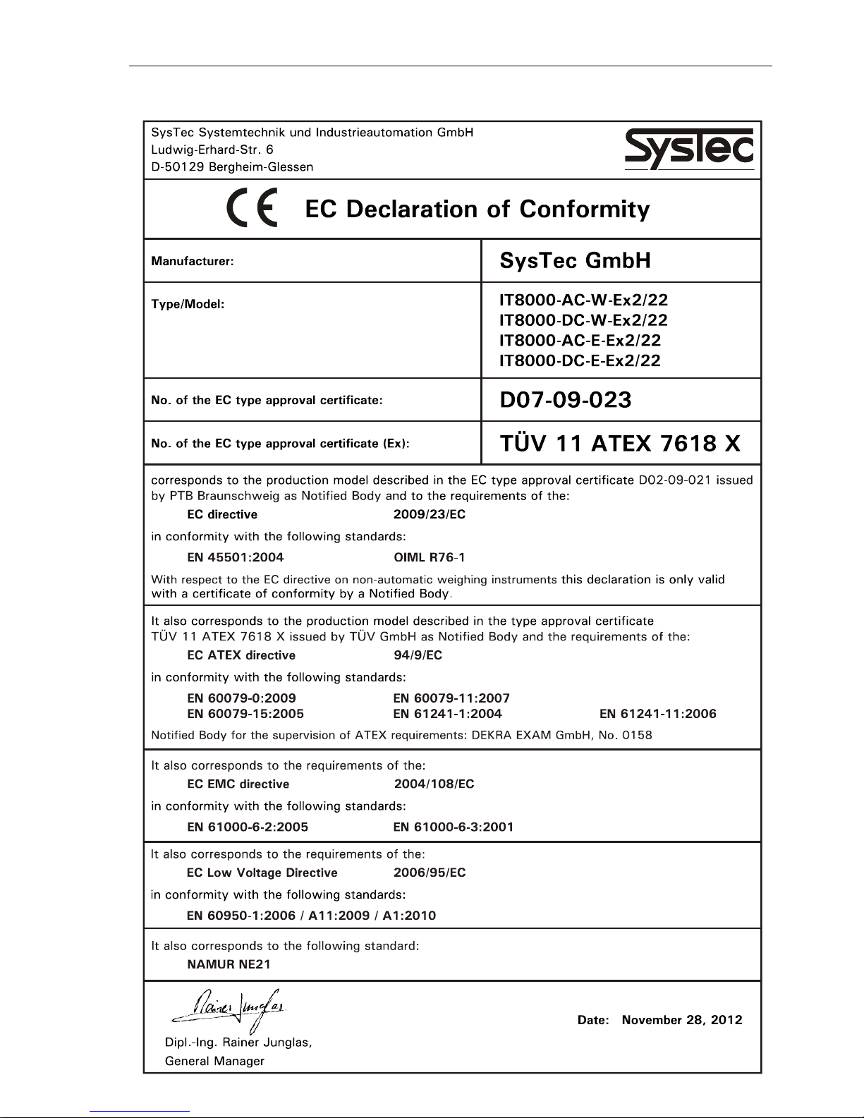
1.4 Declaration Of Conformity............................................................................................. 9
2 Marking............................................................................................................................. 10
3 System Description ............................................................................................................. 11
3.1 General .................................................................................................................... 11
3.2 Basic Units And Options ............................................................................................. 11
3.3 Housing.................................................................................................................... 12
3.4 Main Board CPU8000 ................................................................................................. 13
4 Intended Use ..................................................................................................................... 14
5 Assembly .......................................................................................................................... 15
6 Installation......................................................................................................................... 16
6.1 General .................................................................................................................... 16
6.2 Equipotential Bonding ................................................................................................. 16
6.3 Shielding .................................................................................................................. 16
6.4 Connection Of Cables................................................................................................. 17
7 Installation Of External Connections With Type Of Protection 'Ex-nA' ........................................ 18
7.1 Connection Of Power Supply To IT8000-AC-*-Ex2/22 .................................................... 18
7.2 Connection Of Power Supply To IT8000-DC-*-Ex2/22 .................................................... 19
7.3 Connection Of Analog Scale To ADM / ADC .................................................................. 22
7.4 Connection Of IDNet Scale Base To IDN........................................................................ 25
7.5 Connection Of Digital Scale Bases With RS485 Interface To DWM.................................... 27
7.6 Connection Of Serial Interfaces SIM ............................................................................. 30
7.7 Connection Of Parallel I/Os PIM ................................................................................... 34
7.8 Connection Of Fieldbus Module FBM ............................................................................ 37
7.9 Connection Of Profibus DP Module PCM ....................................................................... 38
7.10 Connection Of Ethernet Module ECM .......................................................................... 40
7.11 Connection Of 15-Bit Analog Output DAU15 ............................................................... 42
8 Commissioning................................................................................................................... 44
8.1 General .................................................................................................................... 44
9 Installation Examples........................................................................................................... 45
9.1 Installation Example IT8000-AC-*-Ex2/22 ..................................................................... 45
9.2 Installation Example IT8000-DC-*-Ex2/22 ..................................................................... 46
9.3 Installation Example IT8000-DC-*-Ex2/22 With Akku-Box................................................ 47
10 Service Mode ................................................................................................................... 48
10.1 General................................................................................................................... 48
10.2 Display And Keyboard .............................................................................................. 49
10.3 Operator Prompting .................................................................................................. 50
10.4 Overview ................................................................................................................ 51
10.5 Interface Configuration ............................................................................................. 52
10.6 Header Ident Data .................................................................................................... 56
10.7 Detail Ident Data ...................................................................................................... 57
10.8 Application Setup..................................................................................................... 58
10.9 RAM Data Backup.................................................................................................... 61

6 Technical Manual IT8000-**-*-Ex2/22 Rev. 4
10.10 Hardware Test ....................................................................................................... 62
10.11 S5 Data Block ........................................................................................................ 68
11 Transport, Maintenance And Cleaning .................................................................................. 69
11.1 Transport ................................................................................................................69
11.2 Maintenance ............................................................................................................ 69
11.3 Replacement Of Fuse (Only IT8000-DC-*-Ex2/22)......................................................... 69
11.4 Cleaning.................................................................................................................. 70
11.5 Security Check.........................................................................................................70
11.6 Functional Test ........................................................................................................ 70
11.7 Repair.....................................................................................................................70
11.8 De-Installation..........................................................................................................70
11.9 Disposal ..................................................................................................................70
12 Trouble Shooting............................................................................................................... 71
13 Technical Data.................................................................................................................. 72
13.1 Basic Units .............................................................................................................. 72
13.2 Options................................................................................................................... 73
13.3 Ex-Relevant Electrical Data For Type Of Protection 'Ex-nA' ............................................. 74
14 Annex ............................................................................................................................. 77
14.1 ACK/NAK-Protocol.................................................................................................... 77
14.2 Exchange Of EPROMs ............................................................................................... 78
14.3 Replacing The Battery ............................................................................................... 81
14.4 Combination Of Options ............................................................................................ 83
15 Dimensions ...................................................................................................................... 84

Technical Manual IT8000-**-*-Ex2/22 Rev. 4 7
1 Introduction
1.1 About This Manual
This manual contains information and Technical Data for the use, the installation and the operation of
the weighing terminal IT8000-AC-W-Ex2/22, IT8000-AC-E-Ex2/22, IT8000-DC-W-Ex2/22 and IT8000DC-E-Ex2/22.
Information applicable to all versions refers to 'IT8000-Ex2/22'. Specific information is marked with the
full designation of the respective version, e.g. IT8000-DC-W-Ex2/22.
The weighing terminal must only be operated by trained personnel.
In addition to this manual further information is provided in the following documentation:
ADM / DUAL-ADM / ADM8000-Exi Calibration Manual, Order-No.: ST.2309.0688
MultiRange Calibration Manual, Order-No.: ST.2309.0057
Revere SLC, Calibration Manual, Order-No.: ST.2309.0362
HBM C16i, Calibration Manual, Order-No.: ST.2309.0248
1.2 Safety Symbols Used In This Manual
Safety relevant information is shown with corresponding symbols as follows:
Ex
W A R N I N G
Failure to observe this precaution could result in serious injuries or fatal accidents due to
ignition of an explosive atmosphere. Please make absolutely sure that these precautions are
observed in order to ensure safe operation of the equipment.
W A R N I N G
Failure to observe this precaution could result in serious injuries or fatal accidents. Please make
absolutely sure that these precautions are observed in order to ensure safe operation of the
equipment.
CAUTION
Failure to observe this precaution could result in damage to or destruction of the equipment or
bodily harm! Please make absolutely sure that these precautions are observed in order to ensure
safe operation of the equipment.
Note: This indicates an advice for the designated use of the equipment and/or additional information to
avoid inappropriate handling.
1.3 Safety Advice
Ex
W A R N I N G
Before opening the housing make absolutely sure that all power sources to this instrument are
disconnected and that no potentially explosive atmosphere can be present at any time!
The de-energized state is reached by disconnecting the supply voltages to the instrument and
to all external devices connected to the interfaces of the weighing terminal.
Ex
W A R N I N G
Exercise utmost care when making checks, tests and adjustments that can actuate movable
parts such as feeding devices, gates, flaps, conveyors, etc. Make absolutely sure that nobody
is within reach of movable parts.

8 Technical Manual IT8000-**-*-Ex2/22 Rev. 4
Ex
W A R N I N G
When this unit is included as a component part of a system, the resulting system design must
be reviewed by qualified personnel who are familiar with the construction and operation of all
individual components in the system and the potential hazards involved.
Ex
W A R N I N G
For installation, service and operation of the unit, the ATEX directive as well as all locally
applicable regulations for safety and the prevention of accidents must be observed!
Ex
W A R N I N G
Input voltage of the instrument must comply with local mains supply!
Ex
W A R N I N G
This module and its associated equipment must only be installed, adjusted and maintained by
qualified personnel authorized by SysTec GmbH!
Ex
W A R N I N G
Connection of peripheral devices to IT8000-Ex2/22 is made in compliance with Ex type of
protection 'Ex-nA'. The values of connected load must be observed. Connected peripheral
devices installed in hazardous area must have appropriate Ex protection.
Ex
W A R N I N G
When the instrument is permanently connected to the power supply, an easily accessible
separator must be included in the supply circuit! It must either be located in safe area or -if
installed in Ex area- have appropriate Ex protection for the place of installation.
Ex
W A R N I N G
The weighing terminal must not be installed in areas where electrostatic charging is possible
which may produce spark discharges, brush discharges or propagating brush discharges at the
front panel.
Comment: According to common knowledge, the use of the equipment and the cleaning with a
damp cloth do not produce such a high surface charge density. However, the front panel must
not be wiped with a dry cloth!
W A R N I N G
Risk of electrical shock! When operating electrical devices, parts of this devices are connected
to dangerously high voltages. Inappropriate use of such devices may lead to serious bodily
injuries or substantial damages to property.
W A R N I N G
The power supply unit of the weighing terminal provides SELV voltages in accordance with EN
60950. Make sure that any peripheral device connected to the weighing terminal containing its
own power supply also uses SELV voltages!
Ex
W A R N I N G
This weighing terminal must not be used in Ex-Zone 0, 1, 20 and 21.
It is the sole responsibility of the employer / operating company to classify the area of
installation (zone, group, temperature class). To that effect, the assistance of the Technical
Supervisory Service or any other technical authority may be utilized!
W A R N I N G
The device uses the short-circuit / overcurrent protection of the on-site mains supply.
Technical Manual IT8000-**-*-Ex2/22 Rev. 4 9
1.4 Declaration Of Conformity
10 Technical Manual IT8000-**-*-Ex2/22 Rev. 4
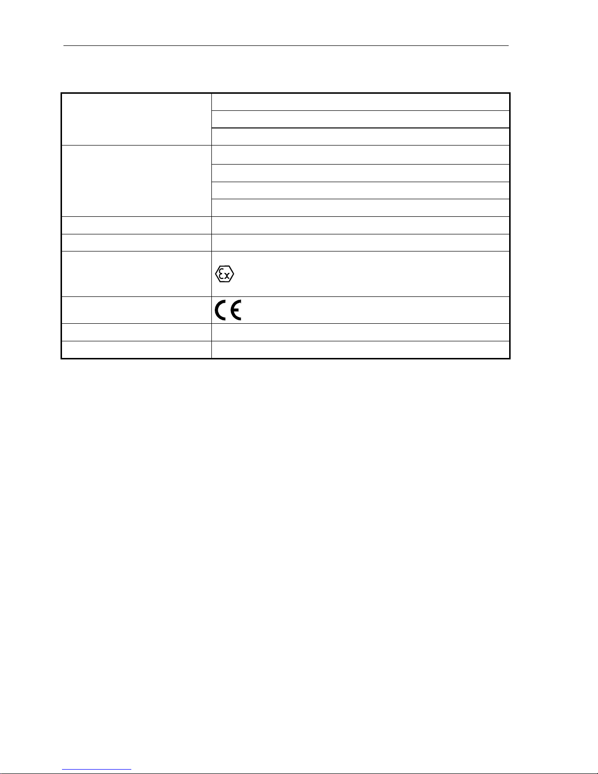
2 Marking
Systec Systemtechnik und Industrieautomation GmbH
Ludwig-Erhard-Straße 6
Manufacturer
50129 Bergheim-Glessen
IT8000-AC-W-Ex2/22
IT8000-AC-E-Ex2/22
IT8000-DC-W-Ex2/22
Designation
IT8000-DC-E-Ex2/22
Serial-No. Ex yy nnnn (yy=year of construction / nnnn=consecutive number)
Range of ambient temperature –10°C to +40°C
Ex classification
II 3G Ex ic nA IIC T4 Gc
II 3D Ex ic tc IIIB T50°C Dc IP54 or
II 3D Ex ic tc IIIC T50°C Dc IP65
CE marking
Type examination certificate TÜV 11 ATEX 7618 X
Service Only by qualified service personnel authorized by SysTec GmbH

Technical Manual IT8000-**-*-Ex2/22 Rev. 4 11
3 System Description
3.1 General
IT8000Ex is a universal weighing terminal for use in a variety of applications such as data logging, data
capturing and set point control, suitable for installation in Ex zones 2 and 22.
It connects to weighing platforms with analog or digital force transducers. The analog version supports
the connection of up to two understructures with a total of up to 16 strain gauge loadcells with an
impedance of 350 each in any combination. By means of an external extension module it is possible
to connect up to 6 additional understructures.
Alternatively, understructures with digital force transducers can be connected.
With its modular concept, the IT8000-Ex2/22 features in its basic configuration three serial interfaces
as well as four parallel opto-isolated inputs and four opto-isolated outputs for external devices. For
more complex applications several interface extension modules are available, for a fourth serial
interface (FBM), Profibus DP (PCM) or Ethernet communication ECM).
The variable I/O design provides up to 64 digital inputs and 64 digital outputs, plus analog inputs /
outputs.
The IT8000-Ex2/22 is freely programmable, operation and program sequence can be easily adapted to
the specific application. Comprehensive standard software is available for standard applications such as
filling, batching, checkweighing, data logging, truck weighing, etc. The design of custom-specific
programs is possible with the RTG program generator which provides the tools for simple and efficient
programming.
3.2 Basic Units And Options
IT8000-Ex2/22 is available in 4 basic versions:
Type Housing Description Article-No.
IT8000-AC-W-Ex2/22 Wall-mount/
desk-top
Basc unit for wall-mount / desk-top installation
with 2.5m line cord with free ends
to connect to 110 - 240 VAC
X8SYS001
IT8000-AC-E-Ex2/22 Panel-mount Basic unit for panel-mount installation
with 2.5m line cord with free ends
to connect to 110 - 240 VAC
X8SYS011
IT8000-DC-W-Ex2/22 Wall-mount/
desk-top
Basc unit for wall-mount / desk-top installation
with screw terminals
to connect to 12 – 30 VDC
X8SYS005
X8SYS006*
IT8000-DC-E-Ex2/22 Panel-mount Basic unit for panel-mount installation
with screw terminals
to connect to 12 – 30 VDC
X8SYS015
X8SYS016*
* The versions X8SYS006 and X8SYS016 feature the main module CPU8000-NTP-Ex2/22 that
provides low-battery indication for battery operation.
12 Technical Manual IT8000-**-*-Ex2/22 Rev. 4
The following modules are available as options:
Option Description Article-No.
ADM Plug-on weighing module for connection of analog loadcells 13OPT100
ADC Plug-on weighing module for connection of analog loadcells 17OPT100
IDN Plug-on module to connect one digital IDNet platform 17OPT101
DWM Plug-on module to connect one digital platform with RS485 interface 17OPT103
SIM-RS232 Plug-on module with serial RS232 interface 10OPT220
SIM-20mA Plug-on module with serial 20mA interface 10OPT221
SIM-RS485.4 Plug-on module with serial RS485 4-wire interface 10OPT222
SIM-RS485.2 Plug-on module with serial RS485 2-wire interface 10OPT225
SIM-RS485.Opto Plug-on module with opto-isolated serial RS485 interface 10OPT230
DAU15 Plug-on module with analog 0/2-10V or 0/4-20mA output 10OPT231
PIM Plug-on module with two digital inputs/outputs 10OPT300
FBM Plug-on module with socket for fourth serial interface 11OPT301
PCM Plug-on module with Profibus-DP interface 17OPT400
ECM Plug-on module with Ethernet interface
(11OPT304-5/10 incl. 5m/10m Ethernet-Kabel)
11OPT304
3V battery 3V lithium battery Varta CR ½ AA 96ZUB002
3.3 Housing
IT8000-Ex2/22 is incorporated in a stainless steel housing with cable glands to connect cables to
peripheral devices. It is available in two versions:
The housing for desk-top / wall-mount installation (IT8000-**-W-Ex2/22) is protected to IP65.
The housing for panel-mount installation (IT8000-**-E-Ex2/22) is inserted in a suitable cutout of a
switch cabinet and fixed from the rear with 8 mounting brackets. When installed accordingly, the front
of the terminal -in combination with the circumferential gasket between terminal and switch cabinet- is
protected to IP65. When installed in Ex zone 2 (as per II 3G Ex ic nA IIC T4 Gc) and Ex zone 22 with
non-conductive dust (as per II 3D Ex ic tc IIIB T50°C Dc IP54) the surrounding housing must be
protected to IP54 or better.
When installed in Ex zone 22 with conductive dust (as per II 3D Ex ic tc IIIC T50°C Dc IP65) the
surrounding housing must be protected to IP65 or better. The surrounding housing (e.g. switch cabinet)
must conform to the requirements of EN60079-0 section 26.4.
Ex
The housings must be included in the equipotential bonding of the installation.
See section 'Dimensions' for space requirements.
Technical Manual IT8000-**-*-Ex2/22 Rev. 4 13
3.4 Main Board CPU8000
The main board contains the Central Processing Unit of the industrial weighing terminal IT8000Ex2/22. It includes the 32bit/16MHz microprocessor 68HC000, 1 MByte battery-backed data,
128 kByte application memory and a battery backed realtime clock..
It is available in three different versions:
Main board Description Used for
CPU8000-230V-Ex2/22 CPU8000 with 110-240 VAC PSU IT8000-AC-*-Ex2/22
Article-No. X8SYS0x1
CPU8000-24VDC-Ex2/22 CPU8000 with 12–30 VDC PSU IT8000-DC-*-Ex2/22
Article-No. X8SYS0x5
CPU8000-NTP-Ex2/22 CPU8000 with 12-30 VDC PSU
and low-bat detection
IT8000-DC-*-Ex2/22
Article-No. X8SYS0x6
Two sockets are provide to insert A/D converters (ADM or ADC) for the connection to understructures
with analog loadcells. Three serial interfaces can be individually configured by means of plug-on
modules (SIM) as RS232, RS485 or 20mA interfaces. Two additional slots can be fitted with plug-on
modules for parallel I/Os (PIM) which contain 2 inputs and two outputs each. For the connection to an
interface expansion board (FBM or PCM) appropriate connectors are available.
Also included on the main board is the wide range power supply, alternatively in AC or DC version.
For information on how to change memory components refer to section 'Changing of EPROMs' in the
annex of this manual.
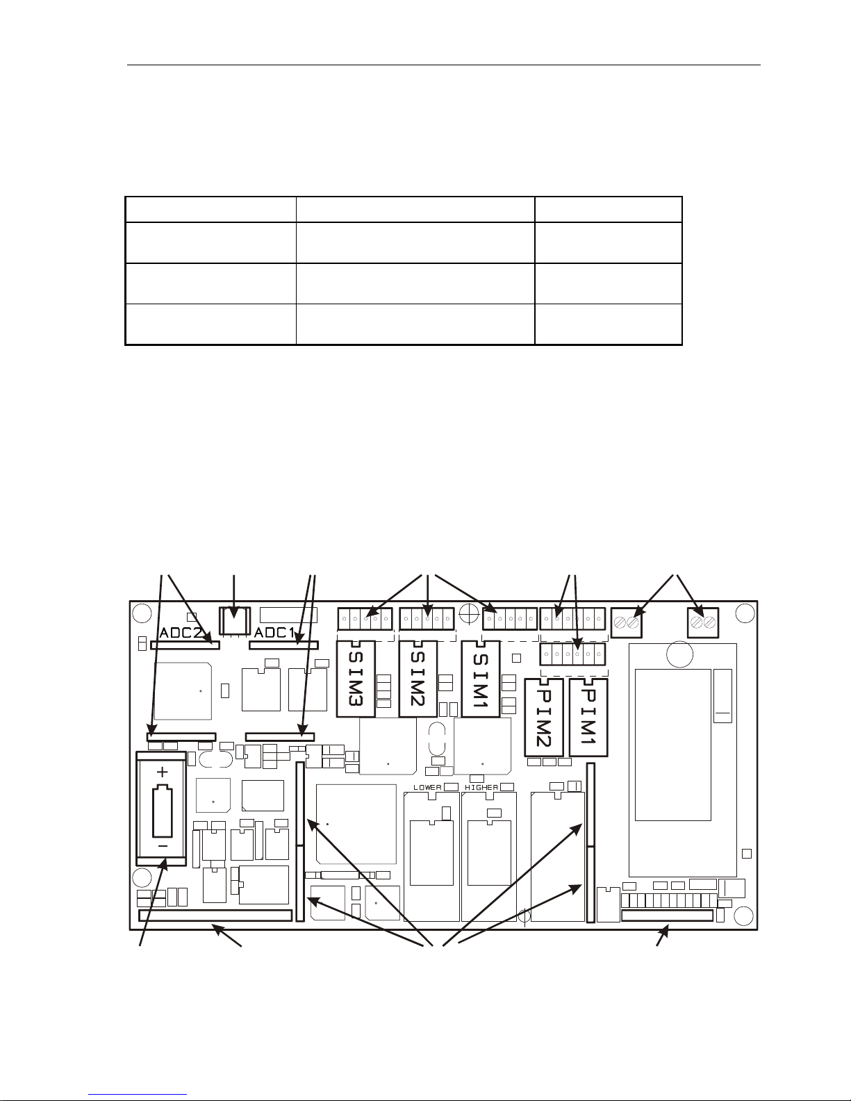
Position of components on the CPU8000 main board
Socket 2 Connector X2 Socket 1 Terminal KL3/KL2/KL1 Terminal KL4/KL5 Connection AC or
for ADM2 (MFII Keyboard) for ADM1 (SIM3/SIM2/SIM1) (PIM2/PIM1) DC power supply
Lithium Connector X7 Connector X8-X11 Connector X1
battery (Display) (Interface expansion) Keyboard
14 Technical Manual IT8000-**-*-Ex2/22 Rev. 4
4 Intended Use
In compliance with RL 94/9/EG (ATEX 95) appendix I, the weighing terminal IT8000-Ex2/22 is
an apparatus of group II category 3G, that following RL 99/92/EG (ATEX 137), can be used in
zone 2, as well as in gas groups IIA, IIB and IIC, which are at risk of explosion through
combustible substances of temperature classes T1 to T4. The following instructions on the
installation of the IT8000-**-E-Ex2/22 in a surrounding housing must be observed.
IT8000-Ex2/22 is also an apparatus of group II category 3D, that following RL 99/92/EG (ATEX
137) can be used in zone 22 (dust), the maximum surface temperature is 50°C. The following
instructions on the installation of the IT8000-**-E-Ex2/22 in a surrounding housing must be
observed.
Applicable only to IT8000-**-E-Ex2/22: The housing for panel-
mount installation is inserted in a
suitable cutout of a switch cabinet and fixed from the rear with 8 mounting brackets. If
installed accordingly, the front of the terminal -in combination with the circumferential gasket
between terminal and switch cabinet- is protected to IP65. When installed in Ex zone 2 (as per
II 3G Ex ic nA IIC T4 Gc) and Ex zone 22 with non-conductive dust (as per II 3D Ex ic tc IIIB
T50°C Dc IP54) the surrounding housing must be protected to IP54 or better. When installed in
Ex zone 22 with conductive dust (as per II 3D Ex ic tc IIIC T50°C Dc IP65) the surrounding
housing must be protected to IP65 or better. The surrounding housing (e.g. switch cabinet)
must conform to the requirements of EN60079-0 section 26.4.
The weighing terminal must not be installed in areas where electrostatic charging is possible
which may produce spark discharges, brush discharges or propagating brush discharges at the
front panel.
All external connections are designed for type of protection Ex 'nA'. The connection values
shown in chapter 'Installation of external connections with type of protection Ex-nA' must be
observed.
Ex
When installed in hazardous area, all peripheral devices connected to IT8000-Ex2/22 must have
appropriate Ex protection.
The metal housing of the IT8000-Ex2/22 terminal must be integrated at the PA stud into the
equipotential bonding system of the installation. Use serrated washers.
The permissible range of ambient temerature is –10°C to +40°C.
When installing IT8000-**-E-Ex2/22 in a switch cabinet (panel-mount version), this
temperature range also apllies to the inside the switch cabinet.
Furthermore, for use and installation all requirements as per EN 60079-14 must be observed.
Any other but the intended use of the equipment, modifications and extensions must not be
made without the explicit approval of the manufacturer and is deemed not to be intended. Part
of the intended use is observance of this Technical Manual and the adherence to inspection and
maintenance instructions and intervals. The manufacturer does not assume any liability
whatsoever for damages resulting from non-intended use. Any risk resulting from non-intended
use is solely borne by the user.
The weighing terminal and all connected components must be integrated into a common sytem
of equipotential bonding.
Protective covers or other parts covering the housing completely or in part must not be used.
Ex
The housing must be protected against permanent exposure to ultraviolet radiation.

Technical Manual IT8000-**-*-Ex2/22 Rev. 4 15
5 Assembly
Ex
It must be made sure that installation of the weighing terminal is only carried out when all
power to the instrument is disconnected and no potentially explosive atmosphere is present.
The weighing terminal must not be installed in areas where electrostatic charging is possible
which may produce spark discharges, brush discharges or propagating brush discharges at the
front panel.
Installation must be made in compliance with the generally accepted rules of technology. In particular
for all work carried out on electrical installations the specific safety regulations must be observed.
The weighing terminal may be installed in Ex zone 2 or 22. The terminal must not be damaged. The
place of installation must be clean.
The IT8000-**-W-Ex2/22 (wall-mount / desk-top version) has mounting brackets for wall or table-top
installation. They must be fixed with suitable screws which are not part of the supply. All screws must
be tightened securely.
The IT8000-**-E-Ex2/22 (panel-mount version) has screw clamps to fix the terminal in the cutout of
the switch cabinet. To connect the bonding conductor, an M5 stud is provided at the rear or bottom of
the housing. Use serrated washers to prevent the nuts from becoming loose.
The permissible temperature range is –10°C to +40°C at a max. of 95% relative humidity (non
condensing). Direct exposure to ultraviolet radiation must be avoided.
For wall-mount installation the unit can be fixed at the wall first and then the cables can be installed
with the front lid open.
Before the device is put into operation, the housing must be closed and tightened securely with the
hexagonal srews provided. The screws must be tightened with a torque of 1.1Nm.
16 Technical Manual IT8000-**-*-Ex2/22 Rev. 4
6 Installation
6.1 General
This apparatus must only be installed by qualified personnel who are familiar with all regulations
applicable to the different types of protection and the methods of installation, as well as the
general principles for the classification of zones. This level of competence must correspond to
the work that is to be carried out and appropriate training should be provided on a regular basis.
When the weighing terminal is to be installed in Ex zone 2 / 22 the regulations as per
EN 60079-14 must be adhered to.
The weighing terminal must not be installed in areas where electrostatic charging is possible
which may produce spark discharges, brush discharges or propagating brush discharges at the
front panel.
It must be made sure during installation of the weighing terminal that all power to the
instrument is disconnected and that no potentially explosive atmosphere can be present at any
time.
Installation must be carried out in compliance with applicable DIN/VDE regulations. Also, all
country-specific regulations must be observed. Connection of supply volatage must be made in
compliance with VDE 0100 and VDE 0160.
Ex
When the instrument is permanently connected to the power supply, an easily accessible
separator must be included in the supply circuit! It must either be located in safe area or -if
installed in Ex area- have appropriate Ex protection for the place of installation.
All cables are led into the housing through Ex cable glands. Strip cable jacket only as long as
required for the wires to reach the screw terminals. Use wire end ferrules with plastic collar on
stranded cable and avoid protruding wires. When assembling the cable glands make sure that
shield of cable is connected inside the cable gland. Observe instructions in section 'Connection
of cables'.
Ex
Before the device is put into operation, make sure that the housing is closed and tightened
securely with all hexagonal srews provided. The screws must be tightened with a torque of
1.1Nm.
6.2 Equipotential Bonding
Ex
In compliance with EN 60079-14 the apparatus must be integrated into the equipotential
bonding system of the installation. The bonding conductor must have a cross section of min.
4mm². To connect the bonding conductor, an M5 stud with serrated washer is provided at the
rear or bottom of the housing.
6.3 Shielding
Ex
Use only shielded connection cables. The shield must be connected at both sides in the cable
glands. It is mandatory to additionally install equipotential bonding as per EN60079-14
paragraph 12.2.2.3 exception b). The bonding conductor must have a cross section of min.
4mm².
Technical Manual IT8000-**-*-Ex2/22 Rev. 4 17
6.4 Connection Of Cables
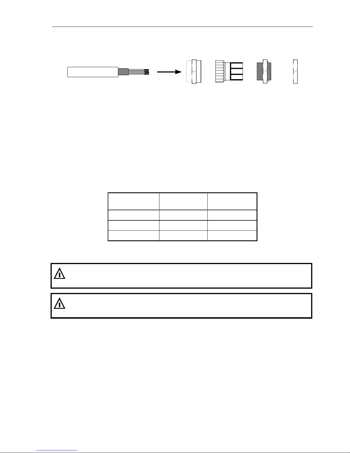
All cables are led into the housing through cable glands.
Cable jacket Shield Compression nut Plastic insert Bushing Counter nut
Cable connection via cable glands:
1. Slide compression nut over cable jacket;
2. Slide plastic insert (retainer) over cable jacket until inner end is aligned with cut end of jacket;
3. Unravel shield, bend over retainer and push into retaining comb. Cut wires of shield to length of
comb, avoid protruding wires;
4. Insert retainer with cable into bushing;
5. Screw compression nut onto bushing and use wrench to tighten securely.
Permissible diameter of cables and torque for cable glands:
Wrench size of
counter nut
Permissible
diameter of cable
Torque to tighten
counter nut
17 mm 4 – 8 mm 6 Nm
20 mm 5 – 10 mm 5 Nm
22 mm 6 – 12 mm 8 Nm
Contact SysTec service for different cable diameters.
Ex
Use crimped wire end ferrules with plastic collar on stranded cable and avoid protruding wires.
Ex
All connecting cables must be firmly installed to avoid tension load at the cable glands and to
comply with the requirements of EN60079-14 paragraph 9.3.1.
18 Technical Manual IT8000-**-*-Ex2/22 Rev. 4
7 Installation Of External Connections With Type Of
Protection 'Ex-nA'
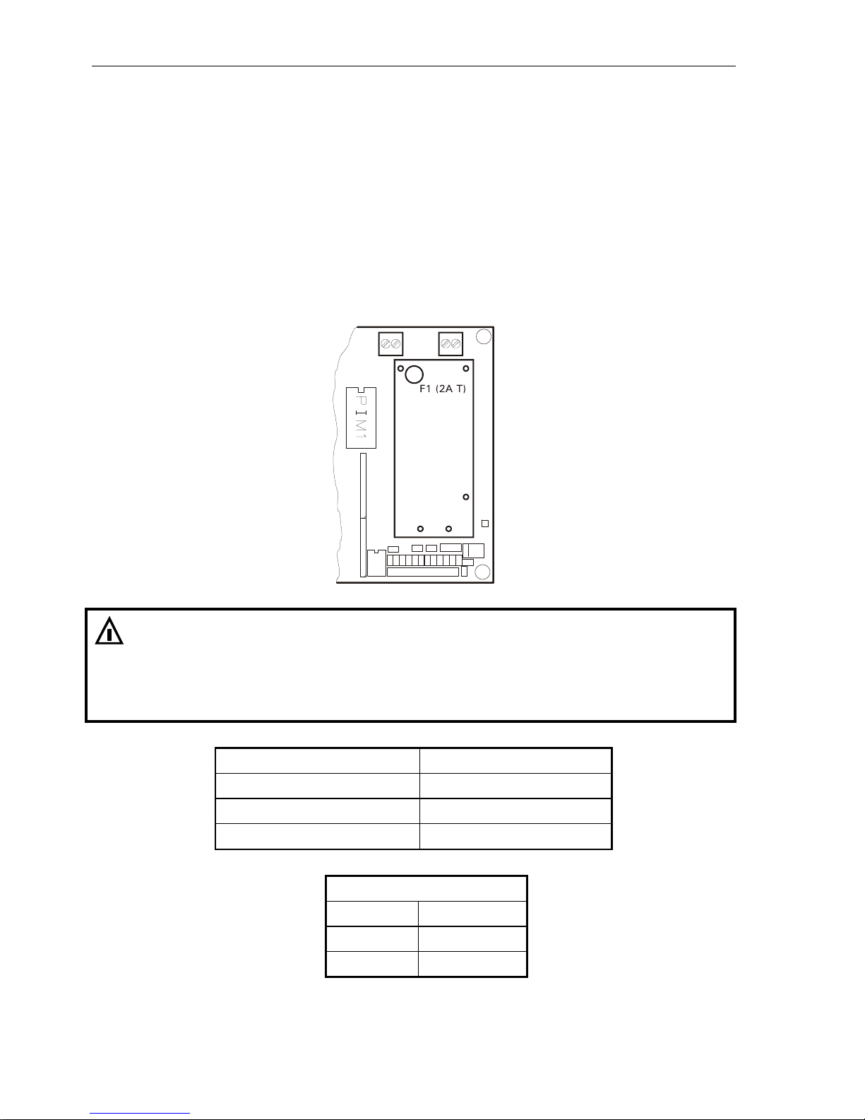
7.1 Connection Of Power Supply To IT8000-AC-*-Ex2/22
IT8000-AC-*-Ex2/22 (article-No. X8SYS0x1) is supplied with a line cord with free ends to connect the
supply voltage.The power supply unit is soldered to the main board CPU8000-230V-Ex2/22. The line
cord is connected to screw terminal KL6 of the CPU8000-230V-Ex2/22.
The power supply has a fused input (2A T). The fuse cannot be replaced.
Terminal KL6
110-240 VAC
PE L1 N
Ex
The connection of the supply voltage at the free cable end of the weighing terminal
IT8000-AC-*-Ex2/22 is designed for type of protection Ex-nA. The listed nominal connection
values must be adhered to.
For the connection of the line cord in hazardous area a suitable method must be chosen in
compliance with EN60079-0 (e.g. Ex-e, Ex-d). A suitable protection against overload and short
circuit in compliance with VDE regulations must be provided.
Nominal voltage UN
110 - 240VAC –15%/+10%
Nominal current IN
300 mA
Frequency range
47 - 63 Hz
Type of protection
Ex-nA
Color code free end of cable
brown L
blue N
green/yellow PE
Technical Manual IT8000-**-*-Ex2/22 Rev. 4 19
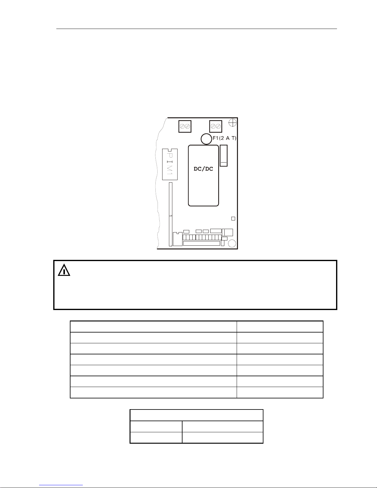
7.2 Connection Of Power Supply To IT8000-DC-*-Ex2/22
The weighing terminal IT8000-DC-*-Ex2/22 is intended for power supply with 12 – 30 VDC. The
connecting terminal KL6 is located on the main board CPU8000-24VDC (for article-No. X8SYS0x5)
and on the CPU8000-NTP-Ex2/22 (for article-No. X8SYS0x6).
A diode is provided as protection against reverse polarity. The power supply of the CPU8000-24VDCEx2/22 has a fused input (2A T). For replacing the fuse see chapter 'Replacing the fuse'.
Terminal KL6
12-30 VDC
PE L1 N
Ex
The connection of the supply voltage to the weighing terminal IT8000-DC-*-Ex2/22 is
designed for type of protection Ex-nA. The listed nominal connection values must be adhered
to.
For the connection of the supply cable in hazardous area a suitable method must be chosen in
compliance with EN60079-0 (e.g. Ex-e, Ex-d). A suitable protection against overload and short
circuit in compliance with VDE regulations must be provided.
Nominal voltage UN: 12 – 30 VDC +10% / –15%
Nominal current IN: 1.5 – 0.5 A
Cross section (rigid wires): 0.75 – 1.5 mm
2
Cross section (flexible wires with insolated wire end ferrule): 0.75 – 1.5 mm
2
Length of stripped insolation: 6 mm
Fastening torque screw terminal: 0.5 – 06 Nm
Ex type of protection: Ex-nA
Terminal assignment CPU8000 terminal KL6
+ V Supply voltage (+)
0 V Supply voltage (—)

20 Technical Manual IT8000-**-*-Ex2/22 Rev. 4
7.2.1 Connecting Cable With Ex Plug For Battery Operation
The weighing terminal IT8000-DC-*-Ex2/22 (article-No. X8SYS0x6) with CPU8000-NTP-Ex2/22 is
suitable for connection to an external rechargeable battery box. To this effect the instrument is
supplied with an assembled connecting cable with ex plug. The following notes must absolutely be
observed:
Absolutely adhere to operating instructions 'Ex-connector mini Clix Reihe 8591'.
Components must have identical coding to avoid damages to connector/socket.
The supply cable to the plug-and-socket connection must be firmly installed and sufficienty
protected against mechanical damage. Cables must comply with the thermic and mechanical
requirements of the location of installation.
When connectors are not connected correctly, protection against risk of explosion is no longer
warranted. Strictly follow the instructions!
After separating, immediately cover components of the plug-and-socket connection conducting
voltage with protective cap!
Ex
For the supply of the weighing terminal the following rechargeable batteries can be used:
1) AkkuBox Ex; 12VDC for use in Ex zone 2 and 22; article-No. E3AKK001
2) Equivalent 12V rechargeable batteries may be used. When a rechargeable battery is used
in hazardous area a suitable type of protection must be provided. Compliance with the
requirements of EN 60079-14 is mandatory.
Observe the operating instructions for the rechargeable battery.
7.2.2 Coding And Pin Assignment Ex Connectors
No. of
pins
Coding Female connector / socket
e.g. AkkuBox Ex
Male connector
IT8000-DC-*-Ex2/22
(article-No. X8SYS0x6)
2 + PE 12 h
Assignment
Pin Voltage
1 12VDC
2 not used
3 GND
PE Shield
Technical Manual IT8000-**-*-Ex2/22 Rev. 4 21
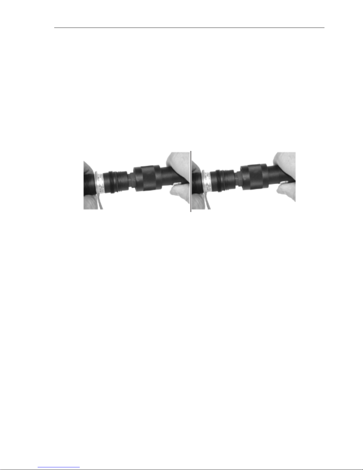
7.2.3 Instructions For Connecting And Separating Coupler
Before plugging in check connectors for any damages.
Align male/female connectors along groove (1).
Push components together up to stop position (2).
Twist right approx. 30° up to stop (3).
Push connectors together completely (4).
Fasten coupling ring tightly (5). This procedure provides for mechanical connection, electrical
contact and IP protection.
Disconnect in reverse order.
22 Technical Manual IT8000-**-*-Ex2/22 Rev. 4
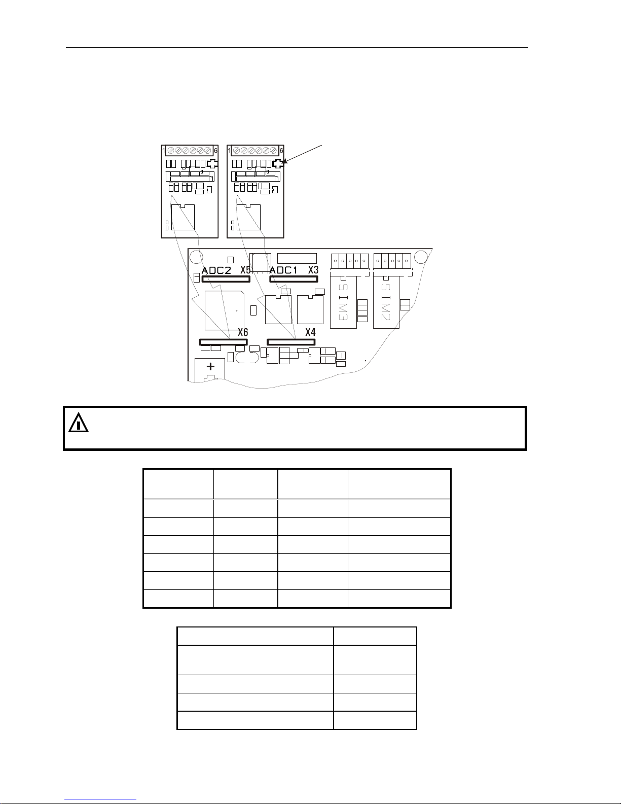
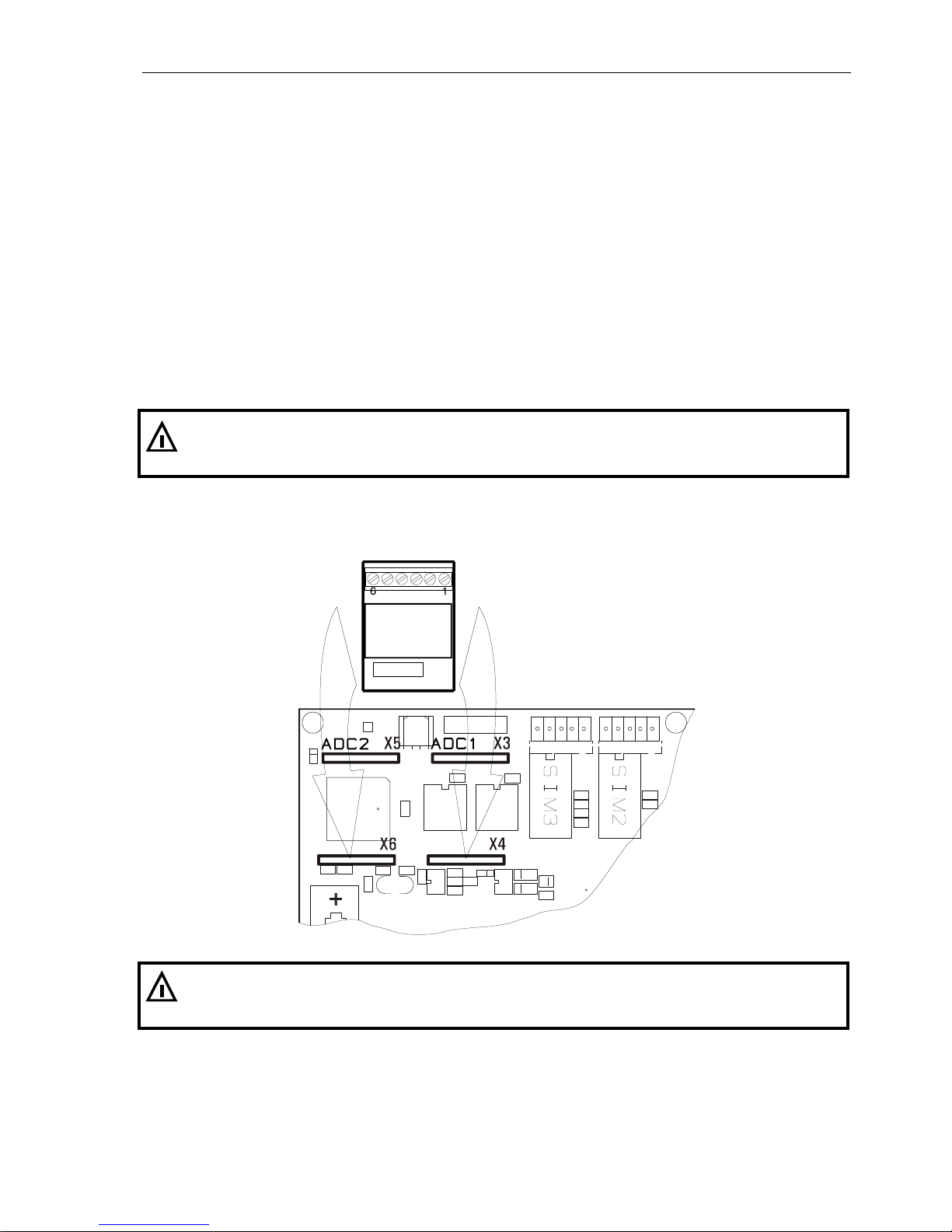
7.3 Connection Of Analog Scale To ADM / ADC
The ADM or ADC provides connection for one weighing platform with strain gauge loadcell(s). A
second weighing platform can be connected using a second ADM or ADC board. The modules are
plugged into sockets ADC1 / ADC2 on the CPU8000 main board.
ADM2 ADM1 Jumper W1
Ex
The connection is designed compliant to type of protection 'Ex-nA'. If the loadcell is to be
installed in hazardous area, compliance with the applicable Ex regulations is mandatory. The
following connection values must be observed:
ADM/ADC
Terminal KL1
Signal Description Nominal value
1 +Excitation Output 5 V / 240 mA
2 – Excitation Output 5 V / 240 mA
3 +Sense Input 5 V / 1 mA
4 – Sense Input 5 V / 1 mA
5 +Signal Input 5 V / 1 mA
6 – Signal Input 5 V / 1 mA
Cross section rigid wire: 0.25 – 1.5 mm
2
Cross section flexible wire
with insolated wire end ferrule:
0.25 – 1.5 mm
2
Length of stripped insolation: 6 mm
Fastening torque screw terminal: 0.5 – 0.6 Nm
Ex type of protection: Ex-nA

Technical Manual IT8000-**-*-Ex2/22 Rev. 4 23
Connection of weighing platforms and loadcells is to be made as specified below:
Max. 16 strain gauge loadcells 350 each
Overall impedance 21.5 ...4500
W&M approved resolution of 6000d at a max. preload of 80%, internal resolution 524,000d
Smallest permissible input signal for approved applications: 0.33 µV / e
Update rate 50 updates / second
Loadcell excitation: 5 V ±5%, gated power supply (ADM), DC (ADC)
Connection in 4- or 6-wire mode.
Principal schematics of 6-wire and 4-wire strain gauge loadcell:
6-wire loadcell
4-wire loadcell
Connection of 6-wire loadcell to ADM or ADC:
Terminal Assignment
1 +Excitation
2 – Excitation
3 +Sense
4 – Sense
5 +Signal
6 – Signal
Connection of 4-wire loadcell to ADM or ADC:
To connect loadcells without sense lines (4-wire connection), two jump leads must be connected at
terminal row KL1 between terminal 1 and 3, and between terminal 2 and 4.
Terminal Assignment
1 +Excitation
2 – Excitation
3
4
5 +Signal
6 – Signal
24 Technical Manual IT8000-**-*-Ex2/22 Rev. 4
7.3.1 Connection Cables For Analog Weighing Platforms
For the installation of connection cables for analog weighing platforms please follow the recommendations listed below:
Only use suitable loadcell cable, (e.g. SysTec order-No. 10KAB214 (3 x 2 x 0,75mm², shielded)
Nominal voltage of cable ±250V.
Unsuitable loadcell cable may affect accuracy.
The shield of the loadcell cable must be connected all around the cable in the cable gland of the
weighing terminal (see also chapter 'Installation' / 'Connection Of Cables'). Loadcells, platforms
junction boxes and the weighing terminal must be integrated into the equipotential bonding of
the sytem. Depending on the situation on site this may require the installation of a separate earth
lead of appropriate diameter (e.g. 16mm²) in parallel to the loadcell cable. If the junction box is
installed in hazardous area it must be designed with appropriate type of protection.
To extend the loadcell cable only use metal junction boxes and connect shield of cable on both
sides inside cable gland.
Distance between loadcell cables and power lines min. 0.5m. Loadcell cables to be installed in
grounded metal conduits, metal hoses or metal cable trays.
Maximum length of connection cable between weighing platform and weighing terminal: 200m.
If tension load is applied to loadcells instead of compression load, connection for +Signal
and –Signal must be transposed.
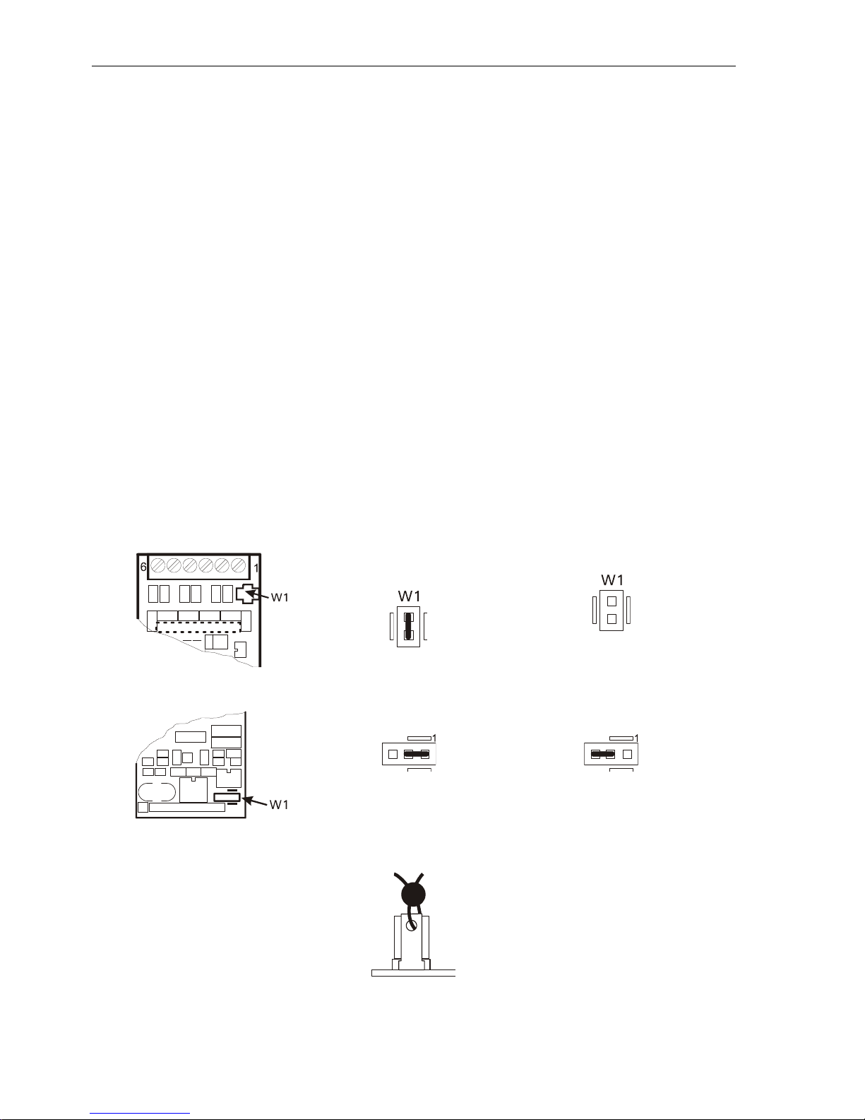
7.3.2 Sealing Of Calibration Parameters
By means of the jumper W1 the calibration parameters stored in EEPROM can be protected against
unauthorized modifications:
ADM in IT8000-Ex2/22 Calibration parameters
protected
Calibration parameters
accessible
ADC im IT8000-Ex2/22 Calibration parameters
protected
Calibration parameters
accessible
If required for W&M approved and stamped systems, the position of the jumper W1 can be sealed with
thread and lead seal:
For a description of the calibration mode refer to the 'Calibration Manual IT8000 ADM and ADC'.
Technical Manual IT8000-**-*-Ex2/22 Rev. 4 25
7.4 Connection Of IDNet Scale Base To IDN
The IDN module (IDNet interface module) permits the connection of one Mettler-Toledo understructure
with IDNet interface. It supports IDNet understructures which operate on 12VDC power supply (e.g.
PikBrick). Understructures which require an additional 32VDC supply cannot be connected.
Only one IDN interface (for 1 understructure) may be installed, which is either inserted in socket ADC1
(if the only scale is an understructure with IDNet interface) or ADC2 (for a mixed setup with digital and
analog scale base). In this case (one ADM/ADC and one IDN) the ADM board must always be installed
in the first socket ADC1, the IDN is then installed in socket ADC2.
In a mixed setup, one analog scale base with up to 8 x 350 loadcells can be connected to the
ADM/ADC interface.
The FBM or ECM module must not be used when an IDN board is in place, because the internal
communication with the IDN module is made via COM4, i.e. this interface is not available for the
fieldbus or Ethernet interface or an additional SIM module.
The IDN module provides a maximum of 12VDC / 150mA as supply for the IDNet scale base.
Ex
W A R N I N G
When an IDN module is installed the the auxiliary voltage (10VDC on CPU8000, terminal KL4)
must not be used.
IDN interface module
IDN
Ex
The connection is designed compliant to type of protection 'Ex-nA'. If the force transducer is to
be installaed in hazardous area, compliance with the applicable Ex regulations is mandatory.
The following connection values must be observed:
26 Technical Manual IT8000-**-*-Ex2/22 Rev. 4
IDN
Terminal KL1
Signal Description Nominal value
1 TxD— — Transmit line 20 mA CL 12 V / 20 mA
2 TxD+ + Transmit line 20 mA CL 12 V / 20 mA
3 RxD— — Receive line 20 mA CL 12 V / 20 mA
4 RxD+ + Receive line 20 mA CL 12 V / 20 mA
5 0 V 0 (12 V) Supply voltage 0 (12 V) / 150 mA
6 +12 V (150mA) +12V Supply voltage 12 V / 150 mA
For a description of the calibration mode refer to the
MultiRange Calibration Manual, Order-No.: ST.2309.0057
Cross section rigid wire: 0.25 – 1.5 mm
2
Cross section flexible wire with insolated wire end ferrule: 0.25 – 1.5 mm
2
Length of stripped insolation: 6 mm
Fastening torque screw terminal: 0.5 – 0.6 Nm
Ex type of protection: Ex-nA
7.4.1 Connection Cables For IDNet Scale Bases
Unsuitable cable may cause loss of data. For the installation of connection cables for IDNet scale bases
please note
Only use suitable connecting cable (data cable), e.g. 6 x 0.25 mm² shielded, SysTec order-No.
10KAB216, or data cable supplied by the manufacturer of the scale base.
Nominal Voltage of cable 250V.
Connect shield of cable at both sides, at cable gland of weighing terminal and at understructure
and/or extension cable. If a difference between potentials is experienced, an appropriate potential
equalization must be installed.
Distance between loadcell cables and power lines: 0.5m. Loadcell cables to be installed in
grounded metal conduits, metal hoses or metal cable trays.
Maximum length of connection cable between weighing platform and weighing terminal: 15m.

Technical Manual IT8000-**-*-Ex2/22 Rev. 4 27
7.5 Connection Of Digital Scale Bases With RS485 Interface To DWM
The DWM module (Digital Weighing Module) permits the connection of digital force transducers
(loadcells) operating on 12VDC power supply and communicating with the IT8000-Ex2/22 via RS485
2-wire or 4-wire network.
Scale bases and loadcells are supported as follows:
Sartorius series IS weighing platforms
Digital HBM series C16i loadcells
Revere series SLC loadcells.
Calibration data can be stored powerfail safe in a serial EEPROM on the DWM module. By means of the
jumper W1 these data can be protected against unauthorized modification.
Only one DWM interface (for 1 understructure) may be installed, which is either inserted in socket
ADC1 (if the only scale is a digital understructure) or ADC2 (for a mixed setup with digital and analog
scale base). In this case (one ADM/ADC and one DWM) the ADM board must always be installed in the
first socket ADC1, the DWM is then installed in socket ADC2.
In a mixed setup one analog scale base with up to 4 x 350 loadcells can be connected to the
ADM/ADC interface.
The FBM or ECM module must not be used when an DWM board is in place, because the internal
communication with the DWM module is made via COM4, i.e. this interface is not available for the
fieldbus or Ethernet communication or an additional SIM module.
The DWM supplies a max. of 12V / 320mA for the digital force transducer(s).
Ex
W A R N I N G
When a DWM module is installed, the following restrictions apply:
The auxiliary voltage (10VDC on CPU8000, terminal KL4) must not be used.
If the current consumption of the digital force transducers exceeds 210mA, the interface
extension socket X8 - X11 must not be used.
If the current consumption exceeds 320mA, an external power supply is required which must
have appropriate type of protection when installed in hazardous area.
DWM Interface module
DWM Jumper W1

28 Technical Manual IT8000-**-*-Ex2/22 Rev. 4
Ex
The connection is designed compliant to type of protection 'Ex-nA'. If the digital scale base is
to be installaed in hazardous area, compliance with the applicable Ex regulations is mandatory.
The following connection values must be observed:
DWM
Terminal
KL1
Assignment
RS485
4-wire
Assignment
RS485
2-wire
Description Nominal value
1 Tx A (Tx+) A (Tx+ / Rx+) + Transmit line RS485 5 V
2 Tx B (Tx—) B (Tx— / Rx—) — Transmit line RS485 5 V
3 Rx A (Rx+) — + Receive line RS485 5 V
4 Rx B (Rx—) — — Receive line RS485 5 V
5 0 V 0 (12 V) Supply voltage 0 (12 V) / 320 mA
6 +12 V (320mA) +12V Supply voltage 12 V / 320 mA
Cross section rigid wire: 0.25 – 1.5 mm
2
Cross section flexible wire with insolated wire end ferrule: 0.25 – 1.5 mm
2
Length of stripped insolation: 6 mm
Fastening torque screw terminal: 0.5 – 0.6 Nm
Ex type of protection: Ex-nA

Technical Manual IT8000-**-*-Ex2/22 Rev. 4 29
7.5.1 Connection Cables For Digital Scale Bases With RS485 Interface
Unsuitable cable may cause loss of data. For the installation of connection cables for digital scale bases
please note:
Only use suitable connecting cable (data cable), e.g. 6 x 0.25 mm² shielded, SysTec order-No.
10KAB216, or data cable supplied by the manufacturer of the scale base.
Nominal Voltage of cable 250V.
Connect shield of cable at both sides, at cable gland of weighing terminal and at understructure
and/or extension cable. If a difference between potentials is experienced, an appropriate potential
equalization must be installed.
Distance between loadcell cables and power lines: 0.5m. Loadcell cables to be installed in
grounded metal conduits, metal hoses or metal cable trays.
The permissible cable length depends on conductor cross section of the chosen data cable and
the current consumption of the connected force transducers. Make sure that excitation voltage
at loadcells does not fall below the minimum excitation voltage as specified by manufacturer.
DWM in IT8000-Ex2/22 Calibration parameters
protected
Calibration parameters
accessible
If required for W&M approved and stamped systems, the position of the jumper W1 can be sealed with
thread and lead seal:

30 Technical Manual IT8000-**-*-Ex2/22 Rev. 4
7.6 Connection Of Serial Interfaces SIM
The three serial interfaces on the CPU8000 as well as the fourth interface on the FBM board can be
individually configured as RS232, RS485 4-wire, RS485 2-wire, RS485 2/4-wire optoisolated or 20mA
CL interfaces by means of SIM plug-on modules.
Please note: When a 20 mA CL interface is used, receiver and transmitter of the IT8000 are always
passive, i.e. supply voltage for the current loops must be provided by the connected peripheral device.
Assignment of serial interfaces on the CPU8000
Insert with notch
pointing to top KL3 KL2 KL1
Assignment of serial interfaces on the FBM board
Insert with notch
pointing to right hand side KL1
Ex
Peripheral devices are connected at CPU8000 screw terminals KL1, 2, 3 and FBM module
screw terminal KL1. The connection is designed compliant to type of protection 'Ex-nA'. The
following connection values must be observed:

Technical Manual IT8000-**-*-Ex2/22 Rev. 4 31
SIM-RS232:
CPU8000 Terminal KL1, 2, 3
FBM Terminal KL1
Description Nominal value
1 TxD ±12 VDC
2 RTS ±12 VDC
3 RxD ±12 VDC
4 CTS ±12 VDC
5 GND ±12 VDC
SIM- RS485 2-wire:
CPU8000 Terminal KL1, 2, 3
FBM Terminal KL1
Description Nominal value
1 A (TxD+/ RxD+) 5 VDC
2 B (TxD– / RxD–) 5 VDC
3 A (TxD+/ RxD+) 5 VDC
4 B (TxD– / RxD–) 5 VDC
5 – –
SIM-RS485 4-wire / SIM-RS485 Opto:
CPU8000 Terminal KL1, 2, 3
FBM Terminal KL1
Description Nominal value
1 TxA (TxD+) 5 VDC
2 TxB (TxD–) 5 VDC
3 RxA (RxD+) 5 VDC
4 RxB (RxD–) 5 VDC
5 – –
SIM-20mA:
CPU8000 Terminal KL1, 2, 3
FBM Terminal KL1
Description Nominal value
1 TXIN 12 VDC / 20 mA
2 TXOUT 12 VDC / 20 mA
3 RXIN 12 VDC / 20 mA
4 RXOUT 12 VDC / 20 mA
5 – –

32 Technical Manual IT8000-**-*-Ex2/22 Rev. 4
The following connection values must also be adhered to:
Cross section rigid wire: 0.14 – 1.5 mm
2
Cross section flexible wire with insolated wire end ferrule: 0.25 – 0.5 mm
2
Length of stripped insolation: 7 mm
Fastening torque screw terminal: 0.22 – 0.25 Nm
Ex type of protection: Ex-nA
Principal circuit diagram of the 20mA current loop interface:

Technical Manual IT8000-**-*-Ex2/22 Rev. 4 33
Principal connecting diagram RS485 network:
Terminal assignment: Some manufacturers of components with RS485 interface do not refer to the
terminals TX+ and RX+ as 'A', but 'B' instead (correspondingly, the terminals TX– and RX– are not
referred to as 'B', but 'A').
Termination resistors: In order to prevent reflection (baud rate 19200 Baud or higher, and/or cable
longer than 20 m) it is recommended to install termination resistors RTerm = 150 on both ends of the
cable. Use only twisted pair cables with a characteristic impedance of approx. 150 .
Pull-up / pull-down resistors: When termination resistors are used, also 390 pull-up and pull-down
resistors must be installed at the master (see also following schematic).
Ex
If termination and pull-up / pull-down resistors are to be used in hazardous area, specific
requirements apply. Contact SysTec service for details.
RS485 network with termination, pull-up and pull-down resistors

34 Technical Manual IT8000-**-*-Ex2/22 Rev. 4
For the installation of connection cables for serial interfaces please follow the recommendations listed
below:
Install data cables to prevent capacitive or inductive interference from other cables, machines
and/or electrical devices that could interrupt data transmission and lead to loss of data.
Non-factory made cables must comply with the following specification:
Shielded twisted pair, e.g. LIYCY 3 x 2 x 0.25mm²,
shield to be grounded on both sides.
Resistance
125 /km
Cross section 0.25 mm2- 0.5 mm
2
Capacitance
130 nF/km
Cable length 20mA max. 100 m
Cable length RS232 max. 15 m
Cable length RS485 max. 1200 m
Impedance RS485
ca. 150
Nominal voltage
250 V
7.7 Connection Of Parallel I/Os PIM
The parallel input/outputs on the CPU8000 can be activated by inserting plug-on modules. Each module
provides drivers for two optoisolated inputs and two optoisolated outputs.
Principal schematics
Parallel output Parallel input

Technical Manual IT8000-**-*-Ex2/22 Rev. 4 35
Position and assignment of parallel inputs/outputs on CPU8000 board
Insert with notch
pointing to top KL5 KL4
Ex
Peripheral devices are connected to the CPU8000 at screw terminals KL4 and KL5. The
connection is designed compliant to type of protection 'Ex-nA'. The following connection
values must be observed:
Terminal assignment
KL4 / 5: parallel inputs and outputs 0 - 3
Terminal 4 Terminal 5 Signal Function Nominal value
1 0V 0V Auxiliary voltage 10 VDC / 100 mA
2 +10V +10V Auxiliary voltage 10 VDC / 100 mA
3 IN0 Input 0 24 VDC / 7 mA
4 IN1 Input 1 24 VDC / 7 mA
5 IN2 Input 2 24 VDC / 7 mA
6 IN3 Input 3 24 VDC / 7 mA
1 In– Gnd for inputs 24 VDC / 28 mA
2 OUT0 Output 0 24 VDC / 100 mA
3 OUT1 Output 1 24 VDC / 100 mA
4 OUT2 Output 2 24 VDC / 100 mA
5 OUT3 Output 3 24 VDC / 100 mA
6 OUT+ External supply for
outputs
24 VDC / 400 mA
Note: The internal 10 VDC supply (terminal row KL4, terminal #2) may be used to connect switches
and push buttons to the digital inputs (100 mA max.). If an interface board to connect digital force
transducers (IDN, DWM) is installed, this auxiliary voltage is not available. External devices connected
to the digital outputs must always be supplied from an external 24 VDC power supply. If connected
components are installed in hazardous area, they must comply with appropriate type of protection, e.g.
'Ex-d'.

36 Technical Manual IT8000-**-*-Ex2/22 Rev. 4
The following connection values must also be adhered to:
Cross section rigid wire: 0.14 – 1.5 mm
2
Cross section flexible wire with insolated wire end ferrule: 0.25 – 0.5 mm
2
Length of stripped insolation: 7 mm
Fastening torque screw terminal: 0.22 – 0.25 Nm
Ex type of protection: Ex-nA
For the installation of cables for digital I/Os please note:
Install I/O cables to prevent capacitive or inductive interference from other cables, machines and/or
electrical devices that could affect input/output signals and lead to malfunction and/or dangerous
operational conditions.
Cables must comply with the following specification:
Shielded multicore cables, shield connected to ground on both sides
Flexible wires with wire end ferrules
Resistance 125 /km
Cross section 0.25 mm2bis max. 0.5mm
2
Capacitance 130 nF/km
Nominal voltage 250 V
Legth of cabble max. 15m
Note:
To achieve maximum suppression of all coupled frequencies, the shield should be connected on
both sides.
If fluctuation of the earth potential is experienced, this can cause an equalization current flowing
over the shield. In this case a separate earth lead of appropriate diameter for potential
equalization is required.

Technical Manual IT8000-**-*-Ex2/22 Rev. 4 37
7.8 Connection Of Fieldbus Module FBM
The FieldBus extension Module can be inserted in socket X8-X11 of the main board and provides a
fourth serial interface. To this effect a SIM interface module is plugged into the corresponding socket.
Connection of the serial interface is made at screw terminal KL1 of the FBM board.
Ex
For connection of a serial inteface to SIM4 on the FBM board refer to chapter 'Connection of
serial interfaces'.
Ex
The use of a fieldbus module in the socket 'Fieldbus controller' on the FBM board is not
permitted for IT8000Ex2/22. This socket must remain free.
KL1
FBM SIM4
Main board

38 Technical Manual IT8000-**-*-Ex2/22 Rev. 4
7.9 Connection Of Profibus DP Module PCM
With the Profibus Controller Module the IT8000-Ex2/22 operates as a Profibus DP slave, with an I/O
interface (64 inputs and outputs) or a data interface with 32 input words and 32 output words. The
PCM module is designed for transmission speeds of 12 MBit/s. The definition of the individual data
words depends on the application and is specified in the Installation Instructions pertaining to the
respective product.
The PCM interface is inserted in socket X8-X11 on the main board.
KL1
PCM Profibus DP
Main board
The Profibus address is set in Service Mode, Group 4 'Configure Application' (see also Installation
Instructions of the applicable program). To set parameters of the Profibus master, the GSD file included in the supply- is used.
Data transmission is made over an isolated RS485 interface complying with the Profibus DP
specification. Connections to the Profibus DP interface are made at terminal KL1 on the PCM board.
Correct operation is indicated with the LED on the board.
If the terminal is connected to a physical end of the Profibus DP bus, the jumpers W1, W2 and W3
must be set to terminate the bus.
Ex
The connection of external Profibus DP participants is made at terminal KL1 of the PCM. The
connection is designed compliant to type of protection 'Ex-nA'. The following connection
values must be observed:

Technical Manual IT8000-**-*-Ex2/22 Rev. 4 39
Terminal assignment Profibus DP interface
Terminal KL1: Profibus DP
Terminal # Profibus DP signal Nominal values
1 RTS 5 VDC
2 Gnd 5V 0 (+5 VDC) / 100 mA
3 +5V +5 VDC / 100 mA
4 / 6 B Line 5 VDC
5 / 7 A Line 5 VDC
The following connection values must also be adhered to:
Cross section rigid wire: 0.14 – 1.5 mm
2
Cross section flexible wire with insolated wire end ferrule: 0.25 – 0.5 mm
2
Length of stripped insolation: 7 mm
Fastening torque screw terminal: 0.22 – 0.25 Nm
Ex type of protection: Ex-nA
Function of jumpers
Jumper Profibus DP interface
W1 Pull-up resistor
W2 Termination resistor
W3 Pull-down resistor
The line is terminated when the jumpers are closed.
For the configuration of the Profibus master, a GSD file is required that you can download from our
website 'www.systecnet.com'.
Follow the link 'Service' and from there to 'download software'.
Download the file 'GSD.ZIP' (click right on the link and choose 'Save Target As...).
Unpack the ZIP file on your hard disk.

40 Technical Manual IT8000-**-*-Ex2/22 Rev. 4
7.10 Connection Of Ethernet Module ECM
With the Ethernet Controller Module the IT8000-Ex2/22 terminal can be connected to Ethernet
networks. The ECM module is plugged into sockets X8-X11 on the CPU8000 board. Connection to the
LAN is made via a prefabricated cable.
The ECM module supports the TCP/IP protocol. Data can be transferred from the nework to the serial
interface COM4 via the port #1234 without change of contents.
The ECM module is configured with the PC program EtherPort Tool which is used to identify the
module in the network and to assign an IP address with the pertaining parameters. Each ECM board
has its unique MAC address which is printed on the side of the Xport module.
IT8000 Service Mode settings for COM4 are as follows: 9600 Baud, format 8N, no handshake (---).
The choice of the transmission protocol depends on the application program on the PC.
The ECM module must not be used when an IDN or DWM board is in place, because these modules
use COM4 for the internal communication with the CPU8000, i.e. COM4 is not available for the
Ethernet interface.
RJ45 connector
ECM for network cable
Main board
Ex
The connection is designed compliant to type of protection 'Ex-nA'. The connection values of
the Ethernet standard (IEEE 802.3) must be adhered to:

Technical Manual IT8000-**-*-Ex2/22 Rev. 4 41
ECM
RJ45 socket
Signal Description Nominal values (Ex-nA)
1 Tx+ Transmit Data + IEEE 802.3
2 Tx- Transmit Data - IEEE 802.3
3 Rx+ Receive Data + IEEE 802.3
4 Rx- Receive Ata - IEEE 802.3
5 Not used Not used IEEE 802.3
6 Not used Not used IEEE 802.3
7 Not used Not used IEEE 802.3
8 Not used Not used IEEE 802.3
Shield Chassis Ground Chassis Ground IEEE 802.3
The 'EtherPort Tool' can be downloaded from our website 'www.systecnet.com'.
Follow the link 'Service' and from there to 'download software'.
Download the file 'EtherPort_Tool.ZIP' (click right on the link and choose 'Save as...).
Unpack the ZIP file on your harddisk. Start 'Setup.exe'.
7.10.1 Ethernet Cable With RJ45 Connector
IT8000-Ex2/22 with ECM module is supplied ex factory with a firmly connected Ethernet cable of 5 m
or 10 m length with RJ45 connector to connect to a local area network.
Ex
If the RJ45 connector of the Ethernet cable is to be connected to the network inside the
hazardous area, an appropriate method of protection in compliance with EN60079-0 (e.g. Ex-e,
Ex-d) must be chosen for the connection. The RJ45 connector itself does not have any Ex
protection and must not be connected/disconnected when a potentially explosive atmosphere is
present!

42 Technical Manual IT8000-**-*-Ex2/22 Rev. 4
7.11 Connection Of 15-Bit Analog Output DAU15
For the output of gross or net weight as analog 15-bit signal a plug-on module (DAU15) can be
inserted instead of a parallel driver module in the PIM socket. The output signal has a resolution of 15
bit (32768 steps). The module can be configured in group 4 'Configuration Of DAU15 Analog Output'
of the Service Mode to 0/2 - 10V or 0/4 - 20mA. The output of the DAU15 module is active and
potential free.
Position and assignment of analog output module DAU15 on CPU8000 board
Insert with notch
pointing to top KL5 KL4
Ex
Peripheral devices are connected to the CPU8000 at screw terminals KL4 and KL5. The
connection is designed compliant to type of protection 'Ex-nA'. The following connection
values must be observed:
Terminal assignment KL4 and KL5:
DAU15 plugged into socket PIM1 or PIM2
KL4 KL5 Signal Description Socket Nominal values
1 -
2 -
3 I+ + Current output 0/4 - 20mA PIM1 10 V / 20 mA
4 I— — Current output 0/4 - 20mA PIM1 10 V / 20 mA
5 I+ + Current output 0/4 - 20mA PIM2 10 V / 20 mA
6 I— — Current output 0/4 - 20mA PIM2 10 V / 20 mA
1 -
2 U+ + Voltage output 0/2 - 10V PIM1 10 V / 20 mA
3 U— — Voltage output 0/2 - 10V PIM1 10 V / 20 mA
4 U+ + Voltage output 0/2 - 10V PIM2 10 V / 20 mA
5 U— — Voltage output 0/2 - 10V PIM2 10 V / 20 mA
6 -

Technical Manual IT8000-**-*-Ex2/22 Rev. 4 43
The following connection values must also be adhered to:
Cross section rigid wire: 0.14 – 1.5 mm
2
Cross section flexible wire with insolated wire end ferrule: 0.25 – 0.5 mm
2
Length of stripped insolation: 7 mm
Fastening torque screw terminal: 0.22 – 0.25 Nm
Ex type of protection: Ex-nA
Example for current output 0/4 - 20 mA (DAU15 in socket PIM1):
Example for voltage output 0/2 - 10 V (DAU15 in socket PIM2):

44 Technical Manual IT8000-**-*-Ex2/22 Rev. 4
8 Commissioning
8.1 General
Prior to start up follow the check list below:
Check to make sure that during commissioning no potentially explosive atmosphere can be
present.
Check whether the conditions concerning the intended use are fulfilled (see section 'Intended
use').
Check assembly as described in 'Assembly'.
Check of installation (equipotential bonding, connection of external components) as described
in chapter 'Installation'.
Check installation as to compliance with EN 60079-14.
Check whether housing is thoroughly closed with all hexagonal srews tightly fastened.
Check to make sure that the components connected to the outputs and interfaces (valves,
movable parts) cannot cause any damage.
Switch on supply voltage.
Configure weighing terminal (interface parameters...) in the Service Mode as described in
section 'Service Mode'.
Calibrate scale as described in Calibration Instructions.
Ex
Test inputs/outputs, serial interface and scale function in Service Mode as described in
section 'Hardware Test'.

Technical Manual IT8000-**-*-Ex2/22 Rev. 4 45
9 Installation Examples
Shown below are three typical system configurations with the weighing terminal IT8000-Ex2/22.
These are principal schematics depicting the options to connect peripheral devices and the connections
in hazardous area as well as in safe area. All devices installed in hazardous area must be designed
compliant to an appropriate type of protection. All sections of this manual and the installation standard
EN 60079-14 must be complied with in full detail.
9.1 Installation Example IT8000-AC-*-Ex2/22

46 Technical Manual IT8000-**-*-Ex2/22 Rev. 4
9.2 Installation Example IT8000-DC-*-Ex2/22

Technical Manual IT8000-**-*-Ex2/22 Rev. 4 47
9.3 Installation Example IT8000-DC-*-Ex2/22 With Akku-Box

48 Technical Manual IT8000-**-*-Ex2/22 Rev. 4
10 Service Mode
10.1 General
The Service Mode is a program for the configuration and the hardware test of the IT8000-Ex2/22
weighing terminal. Additionally, a tool is implemented to back up and restore data when connected to a
PC. The following sections give an introduction on how to operate the terminal via keyboard and
display and describe the individual functions of the Service Mode.
Notes:
IT8000-Ex2/22 and its associated equipment must be installed, adjusted and maintained by
qualified personnel only!
Before accessing the Service Mode all peripheral devices must be installed and configured!
Access to the Service Mode is protected by the Service Password.
Inappropriate changes of Service Mode settings may lead to malfunction and errors in the
operating sequence!

Technical Manual IT8000-**-*-Ex2/22 Rev. 4 49
10.2 Display And Keyboard
Upper display line: Gross or net weight or headline of special functions *)
Lower display line: Prompts, left justified, or parameter entry, right justified *)
Info Forward scrolling
Backwards scrolling
Info
Access to Service Mode
Pressed simultaneously with alpha key: upper case letter
Pressed simultaneously with alpha key: lower case letter
Press three times: activate contrast adjustment, increase contrast
Special keys:
Press three times: activate contrast adjustment, reduce contrast
F1 - F4 Functions depending on application program
F5 (Print) Print F6 (Find) Search entry
Function keys:
F7 (Delete) Delete entry F8 (Esc) Abort function
Clr Clear entry
Clear keys:
Delete last character
Cursor key:
Return to previous program step
Enter key:
Confirm entry, continue with next program step
X Show net weight with tenfold resolution for 5 sec (only in tare
step of operating mode Simple Weighing, if enabled in Service
Mode)
Automatic taring, if scale is tared: clear tare
Set selected scale to zero
Scale keys:
Select scale (applicable only if two scales installed)
*) Depending on the application program the display may be subdivided in a different way (e.g. 4
lines).

50 Technical Manual IT8000-**-*-Ex2/22 Rev. 4
10.3 Operator Prompting
The following sections describe the operating sequence with operator prompts and the requested
entries. In the Service Mode only two out of the maximum of 4 lines are used.
The content of the terminal display is shown in a frame on the left hand side. Next to the display the
possible operator entries are listed, on the right hand side comments and explanations are shown.
Example:
Service Mode
Password ????
Entry of the 4-character service password
Return to normal operation
Prompts or entries that apply only under certain conditions are shown in an extra frame. The condition
is shown in bold face in the upper left hand corner of the frame.
Example:
If detail ident data is specified:
Detail Ident Data
Delete after print Y
1,Y
0,N
ID is cleared after printing.
ID data is not cleared.
This display appears only if ID has been specified.
Enter Key and -Key
In all program steps, unless otherwise specified, the Enter-key leads to the next step. Pressing the key leads to the previous step.
Parameter Choice, e.g. 'Product No. 99':
In program steps that require the selection of a parameter, the options can be displayed by means of
the Info-key (scrolling). By pushing the Enter-key the displayed parameter is selected. The selection
can be exited via the -key.
Select Functions, e.g. 'Select Function 1-2':
In program steps that require the selection of a function, the options can be displayed by means of the
Info-key (scrolling). By pressing the Enter-key the displayed function is selected. Alternatively, the
function can also be started directly by entering the corresponding number in the step 'Select
function'. Function selection can be exited by pressing the -key.
Confirmation with Y (1) or N (0):
A prompt such as 'Save parameters? Y' is confirmed by pressing the key #1 and subsequently the key. By pressing key #0 and -key the proposed action is rejected and in this example the parameters
are not saved.
Numeric Entries (Numerals Only):
A requested numeric entry is depicted by '99999'. The length of the string corresponds to the
maximum length of the entry, (e.g.: 99 = 2 digits, numeric).
Numeric entries are made from right to the left. As defined in the program, entry of decimal point and
minus sign may be accepted. Fixed point data entries already show the right number of decimals.

Technical Manual IT8000-**-*-Ex2/22 Rev. 4 51
Alphanumeric Entry (Letters and Numerals):
A requested alphanumeric entry is depicted by 'XXXXXXX'. The number of x characters corresponds
to the length of the entry. Alphanumeric data entry is made from left to right. If the number of
characters to be entered is greater than the number of characters that can be shown on the display,
the content of the display is shifted to the left by one position for every newly entered character. By
pressing the key the entry can be scrolled to the left - simultaneously pressing the and keys
scrolls the entry to the right.
Adjusting the contrast of the display:
As of version RTP 6.06 of the operating system and IT8000-CPU Index 006, the contrast of the
display can be adjusted via the keyboard. Press the key or three times to activate the adjustment.
Then press the or key again to increase or reduce the contrast in steps. Press any other key to exit
adjustment.
10.4 Overview
After the power up messages with display of program version, date and time, the scale is started and
the program proceeds to the initial step.
W1 0 kg
IT8000 XXXXX V9.99
While program name and version number is displayed
Service Mode can be accessed by simultaneously
pressing the shift and Info keys.
Info Call up Service Mode
Service Mode
Password ????
Entry of the 4-character service password
Return to normal operation
Service Mode
Select Group 1-7
1 Interface configuration
2 Header ident data
3 Detail ident data
4 Application setup
5 Data backup
6 Hardware test
7 S5 Data block
Info Scrolling
F5 Print Setup and configuration data
Backwards scrolling
Return to normal operation
When Service Mode is exited, the entered or modified parameters are stored. Parameters of the groups
1 and 4 (and the factory setting of the device assignment) are stored in Flash-EPROM, whereas all
other parameters are stored in RAM. While Flash-EPROM is updated, a corresponding message is
displayed:
Storing Parameters
Please Wait...
Display while Flash-EPROM is updated

52 Technical Manual IT8000-**-*-Ex2/22 Rev. 4
CAUTION
By no means switch off power during this operation, because that will inevitably destroy the
contents of the Flash-EPROM and thus the program.
Note: If the Info-key is pressed on power up, the version and the checksum of the RTP operating
system are temporarily displayed.
RTP7.2 ID:9999999999
Version and checksum of RTP operating system.
10.5 Interface Configuration
Service Mode
Select Group 1-7
1 Interface configuration
Serial In
terfaces
Scale 1 ADC
Select scale driver for first scale
ADC = Analog L/C connected to ADM/ADC
Mettler = Mettler IDNet protocol
1
)
Sartorius = MC1 compatible protocol (SBI)
2
)
Summing = Summing scale ADM1 + ADM2
or ADC1 + ADC2
IS Scale = Sartorius IS platform
HBM C16i = Digital HBM loadcell
REVERE SLC= Digital Revere SLC loadcell
Disabled = Scale temporarily out of operation
off = No scale
F1 ADC selected: Adapt Mode provides options to
optimize the digital filtering of the captured weight,
refer to the ADM / DUAL-ADM / ADM8000-Exi
Calibration Manual, Order-No.: ST.2309.0688
1
) Intended for Mettler-Toledo scale bases with IDNet interface and 12VDC power supply.
2
) Parameters of the Sartorius scale must be set to:
MC1 protocol (SBI), 7 bit, odd parity, 1200 baud, RTS/CTS, streaming mode, 16-character data
string.
ADC selected and F1 pressed:
Serial Interfaces
Filter Size: 99
Info Select Filter Size to overwrite setting in calibration; 1
(light) to 20 (strong) filtering, 'OFF' and 'CAL' (reset
to value of calibration)
ADC selected:
Serial Interfaces
Scale 1 Intern
Info Select interface for scale 1:
Intern = socket ADC1 or ADC2
COM1...COM4 = external ADCBox
If ADC and COMx is selected:
Serial Interfaces
Extern I/O Module 9
Number of relay and/or transistor modules that are
also connected to the same serial interface. MAI
modules are not counted.

Technical Manual IT8000-**-*-Ex2/22 Rev. 4 53
Mettler, Sartorius MC1 (SBI), HBM C16i or REVERE SLC selected:
Serial Interfaces
Scale 1 COM1
Info Select interface:
COM1 = Interface #1
COM2 = Interface #2
COM3 = Interface #3
Intern = IDN or DWM module in socket ADC1
or ADC2
3
)
3
) Since IDN or DWM modules use interface COM4 for the internal communication, the FBM or ECM
boards cannot be used together with digital scale bases. Only one IDN or DWM board can be
installed.
Please note! If scales with analog loadcells are used together with scales connected to serial interfaces,
the analog (internal) scales must be configured first.
Continue with next scale.
After selecting 'off' or after scale #8:
Serial Interfaces
Com1 Baudrate 99999
Info Select baud rate for serial interface #1:
300, 600, 1200, 2400, 4800, 9600, 19200
Return to 'Select Group'
Serial Interfaces
Com1 Data Format XX
Info Select data format for serial interface #1:
7N = 7 data bits, no parity
7E = 7 data bits, even parity
7O = 7 data bits, odd parity
8N = 8 data bits, no parity
8E = 8 data bits, even parity
8O = 8 data bits, odd parity
Always 1 stop bit is transmitted.
Serial Interfaces
Com1 Handshake XXX
Info Select hardware handshake for interface #1:
CTS = Control via RTS/CTS
XON = Control via XON/XOFF
HDX = Half duplex (for RS485)
4W_XON = Control via XON/XOFF for 4-wire
RS485 connection
––– = No handshake
Setting of RS485 interfaces:
RS485 2-wire HDX
RS485 4-wire, MultiDrop HDX
RS485 4-wire,
SysTec Multidrop protocol for PC BATCH
RS485 4-wire software handshake 4W_XON

54 Technical Manual IT8000-**-*-Ex2/22 Rev. 4
Serial Interfaces
Com1 Protcl. XXXXXXX
Info Select protocol for interface #1:
TTY Printer protocol (data only)
EPSON Printer protocol EPSON ESC/P
AckNak Standard protocol (see below)
No-Ack Standard protocol (see below)
Du3964 DUST 3964 (R)
RK512 RK512 telegram
SinecL1 Sinec L1
(point to point connection for I/Os)
1
)
Ext.Bus External Bus: DeviceBus for Sinec L2 or
external IT8000 extensions
2
)
Special (application-specific)
1
) The Sinec L1 procedure is only implemented because of compatibility with programs written prior
to 1995. Do not use for new applications!
2) By default the interface COM2 is intended for the connection of external IT8000-Ex2/22
components and pre-configured for DeviceBus.
If EPSON was selected as transmission protocol:
Serial Interfaces
Com1 Remote Prt. N
0,N Standard printer protocol
1,Y Remote printer protocol
If AckNak or No-Ack was selected as protocol:
Serial Interfaces
Com1 Start Char. 999
Entry of start character as decimal value
(e.g. 2 = STX)
For entry '0' no start character is transmitted.
Serial Interfaces
Com1 End Char. 999
Entry of end character as decimal value
(e.g. 3 = ETX)
For entry '0' no end character is transmitted.
Serial Interfaces
Com1 Checksum XXX
Info Select 1-Byte checksum to be transmitted after the
end character:
CPL = Complement of two
XOR = Exclusive-Or checksum
––– = No Checksum
Note: For a detailed description of the ACK/NAK protocol see annex.

Technical Manual IT8000-**-*-Ex2/22 Rev. 4 55
If a checksum was selected and a start character specified:
Serial Interfaces
Com1 With Strt Chr Y
1,Y The start character is included in the checksum
calculation
0,N The start character is not included in the checksum
calculation
If a checksum was selected and an end character specified:
Serial Interfaces
Com1 With End Char Y
1,Y The end character is included in the checksum
calculation
0,N The end character is not included in the checksum
calculation
If Du3964 was selected as transmission protocol:
Serial Interfaces
Com1 With Checksum Y
1,Y Transmission with checksum (Dust3964R)
0,N Transmission without checksum
If RK512 was selected as transmission protocol:
Serial Interfaces
Com1 Device-No. 999
Entry of target device-No.
(DB) 0–255
Serial Interfaces
Com1 Word-No. 999
Entry of target word-No.
(DW) 0–255
If Sinec L1 was selected as transmission protocol:
Serial Interfaces
Com1 Inp.Modules 9
Number of 8-bit input modules
Serial Interfaces
Com1 Outp.Modules 9
Number of 8-bit output modules
Note: If Sinec L1 is selected, the digital I/Os of an S5 PLC are read and set via the serial interface
(point to point connection). In this communication the IT8000-Ex2/22 terminal is the
master. The parallel I/Os of the IT8000-Ex2/22 are disabled.

56 Technical Manual IT8000-**-*-Ex2/22 Rev. 4
If DeviceBus was selected as transmission protocol:
Serial Interfaces
Com1 I/O-Module 9
Number of 8-bit input/output modules
Serial Interfaces
Com1 SinecL2
Info Use Info-key to toggle:
SinecL2 or DeviceBus
Note: External IT8000-Ex2/22 extensions are connected via the DeviceBus protocol (in combination
with a 2-wire RS485 interface). This applies to RS485 relay or transistor modules (REL485 /
TRIO485), analog 12-bit I/O modules and external scale multiplexers. By default these
extensions are assigned to interface COM2, which is configured to 'DeviceBus' and 'Number
of I/O modules = 0'. When a value unequal 0 is entered, the I/Os of an external relay /
transistor module are read and set via the serial interface. The parallel I/Os of the IT8000Ex2/22 are then disabled.
This feature is only available for relay and transistor modules with firmware 2.0 or higher,
older versions cannot be connected.
Continued with settings for next interface.
When an IDN or DWM board is installed in socket ADC1 or ADC2, the interface COM4 is not available
any more.
10.6 Header Ident Data
If the application program supports the entry of IDs, they can be defined as 'Header Ident Data' and
'Detail Ident Data' in the Service Mode.
'Header Ident Data' are entered once -e.g. at the beginning of an order- and are valid for each item of
the order. Example: Entry of 'Order-No. ________' for an operating sequence with printout of a
delivery note.
In the Service Mode up to 6 header IDs can be specified, including operator prompts and length of
entry.
Service Mode
Select Groupe 1-7
2 Header Ident Data
Header Ident Data 1
XXXXXXXXXXXXXXXXXXXX
Entry of operator prompt for the first header-ID.
The length of the entry is specified by the number of
remaining underline characters on the right hand side
of the display. The length can be adjusted by entering
space characters behind the operator prompt.
Return to step 'Select Group'

Technical Manual IT8000-**-*-Ex2/22 Rev. 4 57
If ID was defined:
Header Ident Data 1
Delete After Print Y
1,Y The ID is cleared after printout.
0,N The ID is not cleared after printout.
Continued with next ID.
If no ID was defined, or after the sitxth ID, return to step 'Select Group'.
10.7 Detail Ident Data
If the application program supports the entry of IDs, they can be defined as 'Header Ident Data' and
'Detail Ident Data' in the Service Mode.
'Detail Ident Data' are entered at the beginning of each weighing cycle.
Example: Entry of 'Article-No. ________' for an operating sequence with printout of individual
lines per article.
In the Service Mode up to 6 detail IDs can be specified, including operator prompts and length of entry.
Service Mode
Select Group 1-7
3 Detail Ident Data
Detail Ident Data 1
XXXXXXXXXXXXXXXXXXXX
Entry of operator prompt for the first detail-ID.
The length of the entry is specified by the number of
remaining underline characters on the right hand side
of the display. The length can be adjusted by entering
space characters behind the operator prompt.
Return to step 'Select Group'
If ID was defined:
Detail Ident Data 1
Delete After Print Y
1,Y The ID is cleared after printout.
0,N The ID is not cleared after printout.
Continued with next ID.
If no ID was defined, or after the sixth ID, return to step 'Select Group'.

58 Technical Manual IT8000-**-*-Ex2/22 Rev. 4
10.8 Application Setup
The application setup serves to enter the parameters controlling the basic functions of the program.
Listed below are the entries which apply to all application programs. Entry of further parameters may
be required depending on the application program (see also Installation Instructions pertaining to
application program).
Service Mode
Select Group 1-7
4 Application setup
Application Setup
Language XXXXXXXX
Info Language for prompts and messages:
German, English, French, Polish, Dutch, Italian,
Spanish
Return to step 'Select Group'
Application Setup
PC Keyboard DE
Info Select layout for an external PC keyboard:
DE Germany
CH Switzerland
UK Great Britain
US USA / South Africa
FR France
ES Spain
Application Setup
Date Format XXXXXXXX
Info Selection of date format:
DD.MM.YY DD-MM-YY DD/MM/YY
MM.DD.YY MM-DD-YY MM/DD/YY
YY.MM.DD YY-MM-DD YY/MM/DD
D = Day M = Month Y = Year
Application Setup
Decimal Char. XXXXX
Info Select character to separate decimals:
Decimal point (e.g. 0.00)
Comma (e.g. 0,00)
Please note: With the selected decimal character also the transmitted key code is changed accordingly.
Application Setup
Approval Signs Y
1,Y Weights are printed with approval signs in compliance
with former PTB regulations:
Example: Gross/Tare/Net
<25.45kg> / <10.00kg> / <15.45kg>
or <25.45kg> / 10.00kgPT / 15.45kgC
0,N Weights are printed in compliance with EC regulations:
Example: Gross/Tare/Net
25.45kg / 10.00kgT / 15.45kgN
or 25.45kg / 10.00kgPT / 15.45kgN

Technical Manual IT8000-**-*-Ex2/22 Rev. 4 59
Application Setup
Unload After Tare N
Configuration of tare function
1,Y Scale must be unloaded before tare can be cleared or
changed.
0,N Tare can be cleared or changed at any time.
Application Setup
Allow Expand Mode Y
In the tare step the net weight can be displayed with
tenfold resolution for approx. 5 sec after pressing the
X-key.
(Function must be supported by the connected
weighing platform.)
1,Y High resolution display enabled
0,N High resolution display disabled
Important Note:
All entries of further parameters in this group depend on the application program and are described in
the Installation Instructions pertaining to the program.
10.8.1 Fieldbus Interface
Application programs supporting the IT8000 COMBUS module request the configuration of this
interface at this step of the setup sequence.
Application Setup
I/O over Profibus N
Enable / disable control of digital I/Os over Profibus DP
(PCM) instead of PIM modules.
Y Digital inputs/outputs over Profibus DP
N Digital inputs/outputs over PIM modules
Note: If Profibus DP (COM_BUS) is directly supported by the application program, the function 'I/O over
Profibus' must NOT be activated.
I/O over Profibus = Y:
Application Setup
Slaveaddress (0-126)
Enter slave address
Application Setup
Bus Protocol (0-6) _
Select COMBUS protocol:
0 No communication
1 COMBUS DIN 66019
2 Profibus DP
3 Modbus RTU-Format
4 Protocol 3964/3964R
5 Protocol RK512
6 Special Mode

60 Technical Manual IT8000-**-*-Ex2/22 Rev. 4
Depending on the selected protocol entry of further parameters is required:
COMBUS DIN 66019 or Modbus RTU selected:
Application Setup
SlaveAddress(0-31)__
Enter slave address
Application Setup
Debugmode ? N
Enable / disable debug mode
Profibus DP selected:
Application Setup
Slaveaddress (0-126)
Enter slave address
DUST 3964 selected:
Application Setup
No.words received __
Number of output words (as seen from master)
Application Setup
No.words transm. __
Number of input words (as seen from master)
Default setting is 16 input and 16 output words. Transmission is made 10 times per second.
RK512 selected:
Application Setup
Debugmode ? N
Switch on/off debug mode
If debug mode is switched on, status information on received send and fetch commands is available.
Note: After changing the setting for the protocol all interface parameters are reset to default values.

Technical Manual IT8000-**-*-Ex2/22 Rev. 4 61
10.8.2 Configuration Of DAU15 Analog Output
Note: The routine to configure the DAU15 analog output must be implemented in the application
program, it is not included in the default version of the Service Mode.
Only if DAU15 module is installed in PIM socket:
Application Setup
DAU15: PIM1
Assign PIM socket for DAU15 module.
Info Select socket (PIM1 or PIM2).
Application Setup
DAU15: 0-10V
Operating mode (0-20mA, 4-20mA, 0-10V or 2-10V).
Info Select mode.
Application Setup
DAU15: 0V= 6928
Adjust zero.
Connect measuring instrument and check value 0/2V
or 0/4mA.
1 Increase analog signal stepwise.
0 Decrease analog signal stepwise.
Application Setup
DAU15: 10V= 63575
Adjust range.
Connect measuring instrument and check value 10V
or 20mA.
1 Increase analog signal stepwise.
0 Decrease analog signal stepwise.
Note: When the operating mode is changed, the stored values are overwritten
10.9 RAM Data Backup
By means of the PC program Backup & Restore it is possible to backup individual files or all files on a
PC and to restore them at a later time.
With the RTG programming environment also the complete contents of the memory can be transmitted
for test purposes.
Data backup is made via the service channel.
Service Mode
Select Group 1-7
5 RAM data backup
RAM Data Backup
1=RAM /2=Data Base
1 Transfer complete RAM
2 Data base backup
Return to step 'Select Group'

62 Technical Manual IT8000-**-*-Ex2/22 Rev. 4
If complete RAM backup was selected:
RAM Data Backup
Enter 1=to/2=from PC
1 Transfer data to PC
2 Load data from PC
Return to step 'Select Group'
If data base backup was selected:
RAM Data Backup
Please Wait ...
Start PC program 'Backup & Restore'
Return to step 'Select Group'
10.10 Hardware Test
The IT8000 Service Mode provides comprehensive test tools for hardware diagnostics.
Service Mode
Select Group 1-7
6 Hardware test
Hardware Diagnostics
Select Function 1-
8
1 Test serial interfaces
2 Test parallel I/Os
3 Test memory
4 Test display
5 Test keyboard
6 Clear memory
7 Terminate application program
8 Assign devices
Info Forward scrolling
Backwards scrolling
Return to step 'Select Group'

Technical Manual IT8000-**-*-Ex2/22 Rev. 4 63
10.10.1 Serial Input/Output Test
To test a serial interface, characters are output and read back. This requires jump leads between
transmitter and receiver (loop back connector).
Hardware Diagnostics
Select Function 1-8
1 Test serial interfaces
Serial IO Test
Select COM 1-4
Select test serial interfaces with key 1 - 4.
IT8000 terminals without interface extension module
FBM only support COM1 to 3.
Return to 'Select Function'
Serial IO Test
Testing COM 9 ...
Display while interface test is running
Serial IO Test
COM1 is ok
Press any key to continue
If test fails a corresponding message is displayed:
'Port X has failed'.
Return to 'Select COM 1-4'
10.10.2 Parallel Input/Output Test
Hardware Diagnostics
Select Function 1-8
2 Test parallel I/Os
Test of the internal inputs/outputs:
Out: 0000
In: 0000
Status information 0 or 1 for outputs in the upper line
of the display (Output 0 to 3 from right to left).
Status information 0 or 1 for inputs in the lower
display line (Inputs 0 to 3 from right to left).
Return to 'Select Function'
By pressing the 0-key repeatedly the output '0' can be intermittently set or reset. In the same way, the
keys 1 - 3 are used to toggle the outputs 1 to 3. If outputs are wired on inputs, also input test can be
performed.
Test inputs and outputs of external RS485 relay or transistor module:
Only if protocol DeviceBus is selected:
IO Test OUT:00000000
Module 1 IN:00000000
Status information 0 or 1 for outputs in the upper line
of the display. (Outputs 0 to 7 from right to left).
Status information 0 or 1 for inputs in the lower line
of the display. (Inputs 0 to 7 from right to left).
F1 - F8 Select relay or transistor module 1 to 8
Return to step 'Select Function'
By pressing the 0-key repeatedly the output '0' can be intermittently set or reset. In the same way, the
keys 1 - 7 are used to toggle the outputs 1 to 7. If outputs are wired on inputs, also input test can be
performed.

64 Technical Manual IT8000-**-*-Ex2/22 Rev. 4
10.10.3 Memory Test
Hardware Diagnostics
Select Function 1-8
3 Test memory
Memory Test
Testing EPROM ...
Checksum test over CPU-EPROM
Memory Test
Testing RAM ...
Write/read test over CPU-RAM
Memory Test
Memory is OK
If a memory error was detected a corresponding
message is displayed
Return to 'Select Function'
10.10.4 Display Test
Hardware Diagnostics
Select Function 1-8
4 Test display
A block of 120 x 8 pixels (full width and a quarter of
height of the display) is moved from top to bottom to
detect defective pixels.
Return to 'Select Function'
10.10.5 Keyboard Test
Hardware Diagnostics
Select Function 1-8
5 Test keyboard
Keyboard Test
Strike a Key X
The key pressed is displayed
Return to 'Select Function'

Technical Manual IT8000-**-*-Ex2/22 Rev. 4 65
10.10.6 Delete Memory
In this group default setting of configuration parameters (as defined in the initialization part of the
application program) can be restored, after the RAM memory of the terminal is cleared. This reverses
all changes that might have been made in the Service Mode, and it can be required to again configure
the terminal.
The scale calibration is not affected.
Note: After performing the clear memory function all data files are irrevocably lost!
Hardware Diagnostics
Select Function 1-
8
6 Delete memory
Hardware Diagnostics
Delete Memory? N
0,N
Return to step 'Select Function'
1,Y Continue
Hardware Diagnostics
Factory Reset N
0,N Do not restore default setting and proceed
1,Y Restore default setting and proceed
Hardware Diagnostics
Are you sure? N
Verification
0,N,
Return to step 'Select Function'
1,Y Delete memory
Please note that also the language parameter is reset and that the following prompts appear in German.
Factory Reset = Yes:
Parameter speichern
bitte warten...
'Storing Parameters Please Wait'
Display while default setting is restored
Für Neustart Netz
aus- und einschalten
'To Restart Program Switch Power off / on'
The terminal must now be switched off and on again.
After power up the memory is cleared.
If the Factory Reset was skipped, prompts appear in English again on power up. If a Factory Reset was
performed, English must be selected again in group 4 of the Service Mode.

66 Technical Manual IT8000-**-*-Ex2/22 Rev. 4
10.10.7 Terminate Program
This function can be used when the application program is to be stopped for testing or for download of
a new program. Testing and download require the RTG programming environment.
Hardware Diagnostics
Select Function 1-8
7 Terminate application program
Hardware Diagnostics
Exit program? N
0,N,
1,Y
Return to step 'Select Function'
Continue
Service Channel COM1
Program is halted;
Indication of service channnel

Technical Manual IT8000-**-*-Ex2/22 Rev. 4 67
10.10.8 Assignment Of Devices
This function allows the assignment of external devices such as printer or host computer to the serial
interfaces.
The application program accesses external devices via symbolic addresses, e.g. 'Host' or 'Prt1'. The
default assignment of the serial interfaces of the IT8000-Ex2/22 is shown below:
Peripheral Device Symbolic Interface Physical Interface
Host computer Host COM1 (Interface 1, KL1 on CPU8000)
Printer 1 Prt1 COM2 (Interface 2, KL2 on CPU8000)
Printer 2 Prt2 COM3 (Interface 3, KL4 on CPU8000)
Peripheral device 1 Aux1 COM4 (Interface 4, KL5 on FBM)
Peripheral device 2 Aux2 COM5 *)
Peripheral device 3 Aux3 COM6 *)
Service channel COM1
The assignment of physical interfaces to the symbolic interfaces can be changed here.
*) COM5 and COM6 are wildcards, since the terminals has only a max. of 4 physical interfaces.
Hardware Diagnostics
Select Function 1-8
8 Assign devices
Device Assignment
Host Channel is COM1
Assignment of the symbolic address 'Host' to channel
COM1; e.g. enter '2' for COM2.
Return to 'Select Function'
Device Assignment
Prt1 Channel is COM2
Assignment of the symbolic address 'Prt1' to channel
COM2; e.g. enter '3' for COM3.
Continue with Prt2, ...
Note: Support of the channels Host, Prt1, Prt2, Aux1 to Aux3 depends on the application program.

68 Technical Manual IT8000-**-*-Ex2/22 Rev. 4
10.11 S5 Data Block
If parts of the application software are programmed in STEP5, the data words DW0 to DW63 can be
entered to preset variables, timers and/or counters.
The data words DW0 and DW1 are reserved as follows:
DW0 = number of scales (0 .. 3) for the PLC task
DW1 = number of 8-bit input / output modules (0 .. 7)
All other data words are defined in the application program.
Service Mode
Select Group 1-7
7 S5 data block
Service Mode
DW 0 = K?
Entry of data type for data word DW0:
0: KF = Integer number
1: KT = BCD-encoded timer value
2: KZ = BCD-encoded counter value
Return to step 'Select Group'
If data type 'number' was selected:
Service Mode
DW 0 = KF 9999999
Entry of integer number ranging from
–32768 to 32767
Return to previous data word,
from DW0 return to 'Select Group'
F7 Return to entry of data type
If data type 'BCD-encoded timer value' was selected:
Service Mode
DW 0 = KT 999,9
Entry of time with encoded time base ranging from
1,0 to 999,3.
The decimals left to the comma represent the value,
the decimal right to the comma is the encoded time
base:
0 = 0,01s 2 = 1s
1 = 0,1s 3 = 10s
Return to previous data word,
from DW0 return to 'Select Group'
F7 Return to entry of data type
If data type 'BCD-encoded counter value' was selected:
Service Mode
DW 0 = KZ 999
Entry of counter value ranging from
0 bis 999
Return to previous data word,
from DW0 return to 'Select Group'
F7 Return to entry of data type
Continue with next data word.

Technical Manual IT8000-**-*-Ex2/22 Rev. 4 69
11 Transport, Maintenance And Cleaning
11.1 Transport
Notes:
Transport and storage of electronic components such as boards, EPROMS, etc. must only be
made in suitable anti-static ESD bags or cases.
Do not expose the unit to extreme temperatures, humidity, shocks or vibrations.
Storage temperature –10 to +50°C at 95% max. relative humidity without condensation.
11.2 Maintenance
Ex
Maintenance at regular intervals must be carried out by qualified personnel (see chapter
'Installation')
authorized by SysTec GmbH. At these inspections first of all it must be made sure
that the housing is tight, all cables are undamaged and all screws are securely fastened.
Maintenance of scale platforms is required at regular intervals depending on use and environment. The
accuracy of scales can be affected by dirt, foreign objects, etc. and appropriate maintenance is
strongly recommended. Also recommended is the calibration with certified test weights at regular
intervals.
A function check is possible with the program Service Mode.
11.3 Replacement Of Fuse (Only IT8000-DC-*-Ex2/22)
Ex
The power supply input of IT8000-DC-*-Ex2/22 (article-No. X8SYS0x6) with CPU800024VDC-Ex2/22 is protected with the fuse F1. The fuse must only be replaced by qualified
personnel (see chapter 'Installation') authorized by SysTec GmbH. Replacement of the fuse
must only be made when all power sources to the instrument are disconnected and when no
potentially explosive atmosphere can be present. Only a fuse of type TR5 2AT may be used.
Position of the fuse F1 (type TR5 2AT) on the CPU8000-24VDC-Ex2/22

70 Technical Manual IT8000-**-*-Ex2/22 Rev. 4
11.4 Cleaning
Only permit qualified personnel to operate this unit! Disconnect all power to this unit before
cleaning!
The keyboard overlay is resistant against acetone, trichlorine, alcohol, ether, nitric acid (20%),
hexane, sulfuric acid (20%) and all-purpose cleaning agents.
Ex
Clean the keyboard with a soft clean cloth that has been dampened with a mild window type
cleaner. Do not spray cleaner directly on the unit. Concentrated leaches or acids or pure alcohol
must not be used. In order to avoid electrostatic charge, do not rub or wipe the keyboard with
a dry cloth.
If cleaning agents are used that contain leach, acid or alcohol, pure water must be used to
wash off any residue.
11.5 Security Check
Ex
Safe operation is no longer warranted if:
housing or keyboard is damaged
connected cables, cable entry or equipotential bonding are damage
the connected power supply unit is damaged
the display remains dark after switching the unit on.
In these cases disconnect all power to the unit and contact your service station authorized by
SysTec.
11.6 Functional Test
The functionality of the weighing terminal ist tested during calibration of the scale with test weights.
The digital inputs / outputs and the serial interface can be tested in the Service Mode (hardware test).
11.7 Repair
Ex
Immediately disconnect all power to a damaged unit.
Only qualified service personnel (see chapter 'Installation'), authorized by SysTec GmbH, may carry out
repair work using genuine factory supplied spare parts.
11.8 De-Installation
1. Make sure that all power to the weighing terminal and all connected devices is
disconnected and that no potentially explosive atmosphere can be present.
2. Remove cabling.
Ex
3. Use suitable tool to de-install weighing terminal.
11.9 Disposal
For the disposal of the weighing terminal all coutry-specific and locally applicable regulations must be
observed!

Technical Manual IT8000-**-*-Ex2/22 Rev. 4 71
12 Trouble Shooting
Ex
IT8000-Ex2/22 does not contain any customer servicable parts!
IT8000-Ex2/22 may only be installed, adjusted and serviced by qualified personnel!
Ex
The weighing terminal must only be opened when all power to the unit is disconnected.
Ex
Immediately disconnect defective units from all power sources. Only qualified service personnel
(see chapter 'Installation'), authorized by SysTec GmbH, may carry out repair work with
genuine factory supplied spare parts, or serious risks for the user may evolve.
If any problem arises, please follow this check list:
Disconnect the weighing terminal from all power sources.
Check whether all cables including cable glands show any damages.
Check whether housing and keyboard overlay are undamaged.
If operational difficulties are encountered that cannot be rectified by means of this manual, obtain as
much information as possible regarding the particular trouble.
Ex
Fault finding must not be carried out as long as any potentially explosive atmosphere can be
present.
If possible, try first to determine the conditions under which the problem occurs. Try to find out
whether the appearance of the difficulties can be reproduced under the same conditions.
For the systematic analysis of an unknown problem the information as listed below is required:
Serial-No. of the unit and its peripheral components.
Exact wording of any error message displayed.
Type and model of peripheral devices related to the problem (e.g. scale, printer, etc.)
To obtain professional assistance contact your service station stating the information listed above.

72 Technical Manual IT8000-**-*-Ex2/22 Rev. 4
13 Technical Data
13.1 Basic Units
IT8000-**-W-Ex2/22
Stainless steel wall-mount / desk-top housing,
ingress protection IP65, weight: approx. 4 kg;
Housing
IT8000-**-E-Ex2/22
Stainless steel panel-mount housing,
ingress protection see chapter 'Intended use', weight: approx. 4 kg;
Temperature
range
Storage: –10 C to +50 C at 95 % max. relative humidity without condensation,
operation: –10 C to +40 C at 95 % max. relative humidity without condensation;
IT8000-AC-*-Ex2/22
Supply voltage 110 V (–15%) to 240 V (+10%),
frequency: 50 / 60 Hz,
current consumption: max. 0.3A,
power consumption: max. 25 VA;
Connecting values
IT8000-DC-*-Ex2/22
Supply voltage 12 V (–15%) to 30 V (+10%) DC,
current consumption 1.5 – 0.5 A;
Safety
Separation between primary and secondary circuits SELV, compliant to EN60950,
pollution degree 2 (if not IP65), overvoltage category II;
Ex classification
II 3G Ex ic nA IIC T4 Gc
II 3D Ex ic tc IIIB T50°C Dc IP54 or
II 3D Ex ic tc IIIC T50°C Dc IP65;
Display
LCD dot matrix display, 120 x 32 pixels,
height of characters for weights 19 mm, for IDs 9 mm;
Keyboard
Membrane keyboard with tactile feedback, 32 keys incl. numeric keypad, 4 scale
function keys, 8 function keys, entry of alpha characters via multiple key
assignment;
Data backup
Battery backup for data, parameters and files (backup for approx. 1 year without
power supply), optional data backup on PC;
Operating system
Realtime multitasking operating system, programming with RTG program
generator;
Main module
(CPU8000)
32bit/16MHz mikroprocessor 68HC000
1 MByte battery backed data memory,
128 kByte memory for application software,
battery backed real time clock,
sockets for options:
SIM1-3: 3 serial interfaces (SIM)
PIM1-2: 4 optoisolated inputs/outputs (PIM) or
1 analog output (DAU15)
X8-11: 1 interface extension module (FBM) or
1 Profibus module (PCM)
ADM1-2: 2 scale interfaces (ADM) or
1 digital scale interface (DWM) or
1 IDNet scale interface (IDN);

Technical Manual IT8000-**-*-Ex2/22 Rev. 4 73
13.2 Options
Interface extension module
FBM
Interface extension module with socket for fourth serial interface;
Profibus DP module
PCM
Interface extension module with Profibus DP interface;
Ethernet module
ECM
Interface extension module with Ethernet interface;
Analog scale interface
ADM / ADC
Connection of a scale base with analog loadcells, 50 opdates / second,
overall impedance of all connected loadcells 21
Digital scale interface
DWM
Weighing module to connect one digital scale base with RS485
interface;
IDNet scale interface
IDN
Weighing module to connect one digital scale base with IDNet
interface;
Serial interface
SIM-RS232
Baudrate 300 - 19200 Baud,
lenght of cable max. 15 m;
Serial interface
SIM-20mA
Baudrate 300 - 9600 Baud,
lenght of cable max. 1000 m (option); transmitter and receiver passive;
Serial interface
SIM-RS485 2-wire
Baudrate 300 - 19200 Baud,
lenght of cable max.. 1200m (option);
Serial interface
SIM-RS485 4-wire
Baudrate 300 - 19200 Baud,
lenght of cable max. 1200m (option);
Serial interface
SIM-RS485-Opto
Baudrate 300 - 19200 Baud,
lenght of cable max. 1200m (option); optoisolated;
Parallel inputs/outputs
PIM
2 inputs: 24 VDC / 7 mA,
2 outputs: 24 VDC / 100 mA,
potential separation with opto couplers,
external power supply must provide SELV voltages;
Analog output
DAU15
1 analog output for gross or net weight,
selectable 0 - 20 mA, 4 - 20 mA, 0 - 10 V, 2 - 10 V;

74 Technical Manual IT8000-**-*-Ex2/22 Rev. 4
13.3 Ex-Relevant Electrical Data For Type Of Protection 'Ex-nA'
13.3.1 Supply Voltage IT8000-AC-*-Ex2/22
Connection
CPU8000-230V-Ex2/22
Terminal KL6
(cable with free ends)
Description
Nominal connection values
(Ex-nA)
KL6.1
(brown wire)
L
AC supply
(cable ends)
KL6.2
(blue wire)
N
110-240 VAC -15%/+10%
300 mA
13.3.2 Supply voltage IT8000-DC-*-Ex2/22
Connection
CPU8000-24VDC-Ex2/22
CPU8000-NTP-Ex2/22
Terminal KL6
Description
Nominal connection values
(Ex-nA)
KL6.1 +V
DC supply
KL6.2 0 V
12 - 30 VDC +10% / -15%
1,5 – 0,5 A
13.3.3 Serial interfaces SIM1-4
Module
(socket SIM1-4)
CPU8000 KL1-3
FBM KL1
Description
Nominal connection values
(Ex-nA)
KLx.1 TxD ±12 VDC
KLx.2 RTS ±12 VDC
KLx.3 RxD ±12 VDC
KLx.4 CTS ±12 VDC
SIM-RS232
KLx.5 GND ±12 VDC
KLx.1 A (TxD+/ RxD+) 5 VDC
KLx.2 B (TxD - / RxD -) 5 VDC
KLx.3 A (TxD+/ RxD+) 5 VDC
KLx.4 B (TxD - / RxD -) 5 VDC
SIM-RS485-2-wire
KLx.5 – –
KLx.1 TxD+ 5 VDC
KLx.2 TxD– 5 VDC
KLx.3 RxD+ 5 VDC
KLx.4 RxD– 5 VDC
SIM-RS485-4-wire
SIM-RS485-OPTO
KLx.5 – –
KLx.1 TXIN 12 VDC / 20 mA
KLx.2 TXOUT 12 VDC / 20 mA
KLx.3 RXIN 12 VDC / 20 mA
KLx.4 RXOUT 12 VDC / 20 mA
SIM-20mA
KLx.5 – –

Technical Manual IT8000-**-*-Ex2/22 Rev. 4 75
13.3.4 Parallel / Analog Interfaces PIM / DAU15
Module
CPU8000
terminal
KL4, KL5
Description
Module installed
on CPU8000
socket
Nominal connection values
(Ex-nA)
KL4.1 OV – 10 VDC / 100 mA
KL4.2 +10V – 10 VDC / 100 mA
KL4.3 IN0 PIM1 24 VDC / 7 mA
KL4.4 IN1 PIM1 24 VDC / 7 mA
KL4.5 IN2 PIM2 24 VDC / 7 mA
KL4.6 IN3 PIM2 24 VDC / 7 mA
KL5.1 IN- – 24 VDC / 28 mA
KL5.2 OUT0 PIM1 24 VDC / 100 mA
KL5.3 OUT1 PIM1 24 VDC / 100 mA
KL5.4 OUT2 PIM2 24 VDC / 100 mA
KL5.5 OUT3 PIM2 24 VDC / 100 mA
PIM
KL5.6 OUT+ – 24 VDC / 400 mA
KL4.1 – – –
KL4.2 – – –
KL4.3 I+ PIM1 10 V / 20 mA
KL4.4 I– PIM1 10 V / 20 mA
KL4.5 I+ PIM2 10 V / 20 mA
KL4.6
I–
PIM2
10 V / 20 mA
KL5.1 – – –
KL5.2
U+
PIM1
10 V / 20 mA
KL5.3 U– PIM1 10 V / 20 mA
KL5.4 U+ PIM2 10 V / 20 mA
KL5.5 U– PIM2 10 V / 20 mA
DAU15
KL5.6 – – –
13.3.5 Profibus DP Interface PCM
Module
PCM
terminal
Description
Nominal connection values
(Ex-nA)
KL1.1 RTS 5 V / 240 mA
KL1.2 Gnd 5V 5 V / 240 mA
KL1.3 +5 V 5 V / 1 mA
KL1.4 B Line 5 V / 1 mA
KL1.5 A Line 5 V / 1 mA
KL1.6 B Line 5 V / 1 mA
PCM
KL1.7 A Line 5 V / 1 mA

76 Technical Manual IT8000-**-*-Ex2/22 Rev. 4
13.3.6 Ethernet Interface ECM
Module
ECM
RJ45 connector
Description
Nominal connection values (Ex-nA)
compliant to IEEE 802.3
1 Tx+ IEEE 802.3
2 Tx– IEEE 802.3
3 Rx+ IEEE 802.3
4 Rx — IEEE 802.3
5 Not used IEEE 802.3
6 Not used IEEE 802.3
7 Not used IEEE 802.3
8 Not used IEEE 802.3
ECM
Shield Chassis Ground IEEE 802.3
13.3.7 Analog Scale Interface ADM / ADC
Module ADM/ADC terminal Description Nominal connection values (Ex-nA)
KL1.1 +Excitation 5 V / 240 mA
KL1.2 – Excitation 5 V / 240 mA
KL1.3 +Sense 5 V / 1 mA
KL1.4 – Sense 5 V / 1 mA
KL1.5 +Signal 5 V / 1 mA
ADM/ADC
KL1.6 – Signal 5 V / 1 mA
13.3.8 Digital Scale Interface IDN
Module IDN terminal Description Nominal connection values (Ex-nA)
KL1.1 TxD— 12 V / 20 mA
KL1.2 TxD+ 12 V / 20 mA
KL1.3 RxD— 12 V / 20 mA
KL1.4 RxD+ 12 V / 20 mA
KL1.5 0 V 0 (12 V) / 150 mA
IDN
KL1.6 +12 V (150mA) 12 V / 150 mA
13.3.9 Digital Scale Interface DWM
Module IDN terminal Description
Nominal connection values
(Ex-nA)
KL1.1 Tx A (Tx+) 5 V
KL1.2 Tx B (Tx—) 5 V
KL1.3 Rx A (Rx+) 5 V
KL1.4
Rx B (Rx—)
5 V
KL1.5 0 V 0 (12 V) / 320 mA
DWM
KL1.6 +12 V (320mA) 12 V / 320 mA

Technical Manual IT8000-**-*-Ex2/22 Rev. 4 77
14 Annex
14.1 ACK/NAK-Protocol
In group 1 of the Service Mode the transmission protocol for the serial interfaces can be selected. If
the ACK/NAK-protocol is selected, data transmission is made as per the following pattern:
IT8000-Ex2/22 PC
Control Character / Data Example Comment
Start character STX can be selected or deselected in Service Mode
Data fields in ASCII-format Consec.-No.
Date,
Gross,
Net
sequence of data fields with their length, position of
decimal point, etc. depends on application program (e.g.
IT8000 BASIC, IT8000 COUNT, etc.), see also product
related Installation Instructions.
End character ETX can be selected or deselected in Service Mode
Checksum XOR can be selected or deselected in Service Mode, options:
XOR, compliment of two, no checksum
PC IT8000-Ex2/22
Control Character Comment
ACK positive confirmation for correctly received data string
or
PC IT8000-Ex2/22
Control Character Comment
NAK negative confirmation for not correctly received data string
The IT8000-Ex2/22timeout delay for the reception of ACK or NAK is 6 sec. If a response cannot be
received within 6 sec or if a negative response is received (NAK), the transmission of the data string is
repeated up to 4 times. If after a total of 5 transmission attempts a response cannot be received or if
only negative responses are received, an error message is indicated on the display of the IT8000Ex2/22 terminal which must be acknowledged by the operator. The operator has the choice either to
start the transmission anew (e.g. after rectifying the problem) or switch off the data transmission.
As an alternative to the ACK/NAK protocol, several other transmission protocols can be selected in the
Service Mode: DUST3964(R), RK512 telegram, and No-ACK (same as ACK/NAK, however without
confirmation).

78 Technical Manual IT8000-**-*-Ex2/22 Rev. 4
14.2 Exchange Of EPROMs
Ex
W A R N I N G
Before opening the housing to replace EPROMs make absolutely sure that all power sources to
this instrument are disconnected and that no potentially explosive atmosphere can be present
at any time!
The de-energized state is reached by disconnecting the supply voltages to the instrument and
to all external devices connected to the interfaces of the weighing terminal.
Only permit qualified personnel to service this equipment!
Observe precautions for handling electro static sensitive devices!
The program in the IT8000-Ex2/22 terminal resides in 3 EPROMs located on the CPU8000 board. The
operating system with the basic system functions is contained in 2 EPROMs labelled with 'RTP xxx'
and a serial-No. The suffix 'xxx' represents the version (e.g. '5.01'). The labels of the two EPROMs
for the operating system differ in the last character attached to the version-No.: 'L' for 'LOWER' and
'H' for 'HIGHER'.
The application program (BASIC, COUNT, etc.) is contained in the third EPROM that is usually
unlabelled. The application program stored in the third EPROM works only in conjunction with the
appropriate version of the RTP operating system! If the version of the operating system supplied is
identical to the version already installed in the IT8000-Ex2/22 (identical serial-Nos.), only the EPROM
with the application program needs to be changed.
Layout of CPU8000 board
EPROM with RTP operating system EPROM with
EPROM with suffix 'L' LOW (left) application program
EPROM with suffix 'H' HIGH (right)
Note: Make sure only to insert EPROMs with notch pointing up (to the middle of the board)! EPROMs
inserted in the wrong direction are inevitably destroyed on power up!

Technical Manual IT8000-**-*-Ex2/22 Rev. 4 79
14.2.1 Replacing A Complete Set Of EPROMs
(New version of operating system and/or new application program)
Open the housing and refer to sketch shown above to locate CPU-board.
If CPU is fitted with piggyback board, remove carefully by lifting it with both hands.
Use small screw driver or other suitable tool and remove EPROMs carefully from sockets.
Exercise care not to damage components and printed circuits underneath the EPROMs.
Insert new EPROMs into sockets and make sure that all pins are properly aligned and fit into
socket.
If piggyback board had to be removed, insert it at its old location.
Remove jumper W10, wait approx. 20 sec and put it back in place. This clears the RAM on
the CPU board, and on power up the Service Mode settings are automatically loaded from
Flash-EPROM.
Close housing and fasten all screws tightly. Switch on power and/or plug in line cord.
Immediately after power up enter Service Mode, group 6 (Hardware Diagnostics), subgroup
6 (Delete Memory), and choose 'Delete Memory Y' and 'Factory Reset Y'.
Now the terminal carries out a restart and the message 'Save Parameters, Please Wait...'
appears on the display while the default settings are loaded into the Flash-EPROM.
Important note: By no means switch off power during this operation, because that will
inevitably destroy the contents of the Flash-EPROM and thus the program.
14.2.2 Replacing The CPU Board
(Transfer old EPROMs to new board)
Use PC program 'Backup&Restore' to save settings and volatile data, if that is not possible,
at least write down Service Mode settings.
Open the housing and refer to sketch shown above to locate CPU-board.
If CPU is fitted with piggyback board, remove carefully by lifting it with both hands.
Use small screw driver or other suitable tool and remove EPROMs carefully from sockets.
Exercise care not to damage components and printed circuits underneath the EPROMs.
Insert old EPROMs into sockets of new CPU and make sure that all pins are properly aligned
and fit into socket.
Install new CPU in weighing terminal, if piggyback board had to be removed, insert it at its
old location.
Remove jumper W10, wait approx. 20 sec and put it back in place. This clears the RAM on
the CPU board, and on power up the Service Mode settings are automatically loaded from
Flash-EPROM.
Close housing and fasten all screws tightly. Switch on power and/or plug in line cord.
Restore settings and data with PC program 'Backup&Restore' or enter settings as written
down. In any case check Service Mode settings.

80 Technical Manual IT8000-**-*-Ex2/22 Rev. 4
14.2.3 Replacing The Flash-EPROM
(New version of application program)
Use PC program 'Backup&Restore' to save settings and volatile data, if that is not possible,
at least write down Service Mode settings.
Open the housing and refer to sketch shown above to locate CPU-board.
If CPU is fitted with piggyback board, remove carefully by lifting it with both hands.
Use small screw driver or other suitable tool and remove Flash-EPROMs carefully from
socket. Exercise care not to damage components and printed circuits underneath the
EPROM.
Insert the new Flash-EPROM into socket and make sure that all pins are properly aligned and
fit into socket.
If piggyback board had to be removed, insert it at its old location.
Close housing and fasten all screws tightly. Switch on power and/or plug in line cord.
On power up the display remains dark for several seconds while the Service Mode
parameters are copied from the CPU's RAM into the Flash-EPROM.
Important note: By no means switch off power during this operation, because that will
inevitably destroy the contents of the Flash-EPROM and thus the program.
Restore settings and data with PC program 'Backup&Restore' or enter settings as written down.
In any case check Service Mode settings.

Technical Manual IT8000-**-*-Ex2/22 Rev. 4 81
14.3 Replacing The Battery
Ex
W A R N I N G
Before opening the housing to replace the battery make absolutely sure that all power sources
to this instrument are disconnected and that no potentially explosive atmosphere can be
present at any time!
The de-energized state is reached by disconnecting the supply voltages to the instrument and
to all external devices connected to the interfaces of the weighing terminal.
Ex
The battery must only be replaced by qualified personnel (see chapter 'Installation') authorized
by SysTec GmbH. Replacement must only be carried out in a de-energized state and in the
absence of any potentially explosive atmosphere.
Replace only with 3V Lithium battery of type Varta CR ½ AA. Observe correct polarity!
Disposal of used batteries only as indicated by manufacturer.
3V Lithium battery
Type: Varta CR ½ AA
observe polarity
The life time of the lithium battery that backs up RAM and realtime clock is at least three years in
normal operation. Thus, the battery needs to be replaced at 3-year intervals by a trained service
technician.
To replace the battery, service kit 16ZUB001 is required. This kit consists of a 3V battery (2 size AA
alkaline batteries in row), incorporated in a plastic housing with 2 connecting leads, LED and switch. If
switch is on, LED must be lit to indicate that voltage is higher than 2V. If this is not the case batteries
must be replaced.

82 Technical Manual IT8000-**-*-Ex2/22 Rev. 4
To replace the battery proceed as follows:
Disconnect all power to the instrument, unplug line cord.
Open the IT8000-Ex2/22 housing and refer to picture below to locate CPU8000 board.
Use small screw driver or other suitable tool and carefully remove bracket from battery holder.
Switch on service kit, LED must be lit. Connect leads with test clamps at battery holder. Do not
short circuit, observe polarity!
Carefully remove old battery from holder and insert new one. To prevent loss of RAM contents
make sure that test clamps do not come off.
Remove test clamps, put bracket of battery holder back in place.
Close housing and power the instrument up. Display of IT8000-Ex2/22 shows power up
message. The unit is operational again.
Connection of service kit for change of battery:
Service kit Lithium battery
Art.-No. 16ZUB001

Technical Manual IT8000-**-*-Ex2/22 Rev. 4 83
14.4 Combination Of Options
The interface boards to connect digital force transducers (IDN, DWM) as well as the extensions for
fieldbus and Ethernet connection (FBM, ECM) use the same serial interface COM4 for the internal
communication, i.e. it is not possible to use more than one of these options at a time. The rating of the
IT8000 power supply is 5V (2A max.). All other voltages are generated from this supply by means of
DC/DC converters. Thus, it must be made sure that the 5V power supply is not overloaded (e.g. by the
connection of digital force transducers). This leads to restrictions for the combination of several
options as shown in the following table.
Ex
W A R N I N G
Only the combinations of options shown below must be used. Other combinations may lead to
overheating of the electronics and the risk of explosion.
Scale interface
ADC / IDN / DWM
Analog
loadcells
(350 )
Option
FBM or ECM
Option
PCM
Auxiliary voltage
10VDC / 100mA
Yes —
1 or 2 ADM/ADC
max. 16 in
any
combination
— Yes
Yes
1 IDN — — Yes —
1 DWM (I 210mA)
—
— Yes —
1 DWM (210mA I 320mA) *)
—
— — —
1 IDN
1 ADM/ADC
max. 8 — Yes —
1 DWM (I 210mA)
1 ADM or ADC
max. 4 — Yes —
1 DWM (210mA I 320mA) *)
1 ADM or ADC
max. 4 — — —
*) The current consumption depends on type and number of the connected force transducers. A set
of 4 digital HBM C16i loadcells -for instance- has a typical power consumption of 200mA.

84 Technical Manual IT8000-**-*-Ex2/22 Rev. 4
15 Dimensions
Desk-top installation Wall-mount installation
Holes for wall-mount installation
Panel-mount housing Cutout in front panel
Blackbox housing (type S2)
 Loading...