

Technical Manual
IT3000A
Industrial Weighing Terminal
October 2007
ST.2309.0667
Rev. 4
© SysTec GmbH • Ludwig-Erhard-Str. 6 • D 50129 Bergheim-Glessen
Tel.: 02238 / 9663-0 • Fax.: 02238 / 9663-10
Web: www.systecnet.com • E-Mail: info@systecnet.com

2 Technical Manual IT3000A Rev. 4

Technical Manual IT3000A Rev. 4 3
Technical Manual IT3000A
Date: October 22, 2007
File: IT3000A_THE.DOC
Program Version: 2.41

4 Technical Manual IT3000A Rev. 4
Published By:
SysTec GmbH, Ludwig-Erhard-Str.6, D-50129 Bergheim-Glessen, Germany
All rights reserved. No part of this publication may be reproduced, stored in a retrieval system, or
transmitted in any form or by any means, mechanical, photocopying, recording, or otherwise, without the
prior written permission of SysTec GmbH.
Copyright © 2005 by SysTec GmbH
Terms and product names mentioned in this publication are trademarks, registered trademarks or
service marks of their respective owners. Use of a term should not be regarded as affecting the
validity of any trademark, registered trademark or service mark.
EPSON ESC/P® is a registered trademark of the SEIKO EPSON Corporation.
TOLEDO® is a registered trademark of Mettler-Toledo Inc.
Please Note:
While every precaution has been taken in the preparation of this manual, SysTec GmbH assumes no
responsibility for errors or omissions. Neither is any liability assumed for damages resulting from the use of
the information contained herein.
The publisher is grateful for any information and/or advice that may contribute to correct errors or
omissions in following editions.

Technical Manual IT3000A Rev. 4 5
Contents
1 Introduction .............................................................................................................9
1.1 General..............................................................................................................9
1.2 Safety Symbols Used In This Manual.....................................................................9
1.3 Safety Advice.....................................................................................................9
1.4 Declaration Of Conformity.................................................................................. 11
2 System Description .................................................................................................12
2.1 Construction.....................................................................................................12
3 Description Of Components .....................................................................................13
3.1 Main Module CPU3000A ...................................................................................13
3.2 Display ............................................................................................................13
3.3 Power Supply 110 - 240 VAC ............................................................................14
3.4 Power Supply 12 - 30 VDC ................................................................................14
4 Installation .............................................................................................................15
4.1 Safety Advice...................................................................................................15
4.2 Setup Of The Instrument....................................................................................15
4.3 Opening Of The Housing .................................................................................... 15
4.4 Connection Of Cables........................................................................................15
4.5 Connection Of Scale.......................................................................................... 16
4.5.1 Analog Understructures And Loadcells ..................................................... 16
4.5.2 Connection Of 1 Scale Base Via ADM...................................................... 16
4.5.3 Connection Of 2 Scale Bases Via Dual-ADM .............................................17
4.5.4 Connection Cables.................................................................................17
4.5.5 Multiple-Range Scale.............................................................................. 18
4.5.6 Multi-Interval Scale ................................................................................19
4.5.7 Adaptation To Scale Environment ............................................................ 20
4.5.8 Setting Of Geo Value .............................................................................20
4.5.9 Weights & Measures Approved Applications .............................................20
4.5.10 Securing Scale Parameters....................................................................21
4.6 Serial Interfaces................................................................................................22
4.6.1 Connection Of Serial Interfaces ...............................................................22
4.6.2 SIM RS485.OPTO..................................................................................22
4.6.3 RS485 Network ....................................................................................23
4.6.4 Cables For Serial Interfaces.....................................................................24
4.7 Connection Of Parallel I/Os................................................................................. 25
4.8 Connection Of 8-Bit Analog Output DAU .............................................................26
4.9 Connection Of 15-Bit Analog Output DAU15........................................................28
4.10 Mains Connection ...........................................................................................30
5 Service Mode ......................................................................................................... 31
5.1 General............................................................................................................31
5.2 Display And Keyboard .......................................................................................32
5.2.1 Multiple Assignment Of Numeric Keypad ..................................................33
5.3 Operator Prompting ...........................................................................................33
5.4 Overview .........................................................................................................34
5.5 Overview Service Mode .....................................................................................36
6 Calibration .............................................................................................................38
6.1 Entering Calibration Mode ..................................................................................38
6.2 Select Group ....................................................................................................39
6.3 Scale Parameters ..............................................................................................40
6.4 Calibration........................................................................................................43
6.5 Linearization .....................................................................................................45
6.6 Zero Adjust ......................................................................................................46
6.7 Adaptation .......................................................................................................47
6.8 High Resolution ................................................................................................49
6.9 Reset Parameters ..............................................................................................50
6.10 Calculate Span................................................................................................51
6.11 W&M Info ......................................................................................................52
6.12 Factory Calibration ..........................................................................................53

6 Technical Manual IT3000A Rev. 4
6.13 Geo Values ....................................................................................................53
7 Interface Configuration............................................................................................ 55
8 Configuration Of Data Entry And Print Format ............................................................ 58
8.1 Configuration Of Fields ...................................................................................... 58
9 Entry Of Parameters................................................................................................ 63
10 Operating Modes .................................................................................................... 69
10.1 Weighing Functions......................................................................................... 69
10.1.1 Tare Memory ...................................................................................... 71
10.2 Tare Functions................................................................................................ 72
10.2.1 Set / Clear Tare................................................................................... 72
10.2.2 Autoclear Tare .................................................................................... 72
10.2.3 Repetitive Tare.................................................................................... 72
10.3 Operating Mode 'BASIC'.................................................................................. 73
10.4 Operating Mode 'COUNT' ................................................................................ 74
10.5 Operating Mode 'TRUCK'................................................................................. 79
10.6 Operating Mode 'FILL 1' .................................................................................. 81
10.7 Operating Mode 'FILL 2' .................................................................................. 83
10.8 Operating Mode 'CHECK'................................................................................. 86
10.9 Operating Mode 'TRUCK ONLINE'..................................................................... 87
10.10 Operating Mode 'BASIC/COUNT' .................................................................... 87
11 Backup.................................................................................................................. 88
12 Restore ................................................................................................................. 88
13 Hardware Test .......................................................................................................89
14 Entry Of Parameters For Analog Output..................................................................... 90
15 Reset .................................................................................................................... 91
16 Online Mode .......................................................................................................... 92
16.1 Structure Of Data Strings ................................................................................ 92
16.2 Overview Commands ...................................................................................... 93
16.3 Read Weights ................................................................................................. 94
16.4 Taring............................................................................................................ 97
16.5 Select Scale ................................................................................................... 98
16.6 Set Scale To Zero ........................................................................................... 99
16.7 Display Of Text And Entries ............................................................................. 99
16.8 Printing........................................................................................................ 104
16.9 Read / Set Digital I/Os ................................................................................... 105
16.10 Key And Error Codes ................................................................................... 107
16.11 Multidrop Connection .................................................................................. 108
16.11.1 Establish And Terminate Connection .................................................. 108
16.11.2 Example (Polling Of Slave 1 And Slave 2)........................................... 109
17 Spervisor Mode .................................................................................................... 110
17.1 Entry of Parameters ...................................................................................... 110
17.2 Data Archive ................................................................................................ 112
17.2.1 View Stored Records ......................................................................... 113
17.2.2 Show Data Archive Info ..................................................................... 113
17.3 Error Report ................................................................................................. 114
18 Configuration Examples ......................................................................................... 115
18.1 Example 'BASIC'........................................................................................... 115
18.2 Example 'COUNT'......................................................................................... 122
18.3 Example 'TRUCK' ......................................................................................... 123
18.4 Example 'FILL'.............................................................................................. 126
18.5 Factory Setting............................................................................................. 127
18.6 Field Length Of System Variables.................................................................... 128
18.7 Form For Print Layouts (80 Columns) .............................................................. 129
18.8 Form For Print Layouts (40 Columns) .............................................................. 130
18.9 Form For Configuration.................................................................................. 131

Technical Manual IT3000A Rev. 4 7
19 Data Transmission ................................................................................................132
19.1 Data Transmission Example 1 .........................................................................133
19.2 Data Transmission Example 2 .........................................................................134
19.3 Data Transmission Example 3 .........................................................................135
19.4 Protocol For Data Transmission....................................................................... 136
19.5 Continuous Output ........................................................................................137
19.5.1 SysTec Protocol ................................................................................137
19.5.2 Flintec Protocol .................................................................................137
19.5.3 Spec 1 Protocol.................................................................................137
19.5.4 Spec 2 Protocol.................................................................................137
19.5.5 Schauf Protocol................................................................................. 137
19.5.6 TOLEDO® Protocol ............................................................................. 138
19.5.7 TOLEDO® TSM Protocol .....................................................................138
20 Transport, Maintenance And Cleaning .....................................................................140
20.1 Transport ..................................................................................................... 140
20.2 Maintenance................................................................................................. 140
20.3 Cleaning.......................................................................................................140
21 Trouble Shooting ..................................................................................................141
21.1 Exchange Of OTPs ........................................................................................ 142
21.2 Error Messages ............................................................................................. 144
22 Technical Data .....................................................................................................147
23 Dimensions .......................................................................................................... 148
24 Service Password .................................................................................................149

8 Technical Manual IT3000A Rev. 4
Technical Manual IT3000A Rev. 4 9
1 Introduction
1.1 General
This manual contains information and Technical Data for installation and operation of the IT3000A
industrial weighing terminal. It is structured in the main chapters:
• Modules and connections
• Calibration
• Service Mode for configuration and settings
• Online mode
• Configuration examples.
1.2 Safety Symbols Used In This Manual
Safety relevant information is shown with corresponding symbols as follows:
W A R N I N G
Failure to observe this precaution could result in serious injuries or fatal accidents. Please make
absolutely sure that these precautions are observed in order to ensure safe operation of the
equipment.
CAUTION
Failure to observe this precaution could result in damage to or destruction of the equipment or
bodily harm! Please make absolutely sure that these precautions are observed in order to ensure
safe operation of the equipment.
Note: This indicates an advice for the designated use of the equipment and/or additional information
to avoid improper handling.
1.3 Safety Advice
W A R N I N G
Disconnect all power to this instrument before opening the housing! Risk of electrical shock!
W A R N I N G
Exercise utmost care when making checks, tests and adjustments that can actuate movable
parts such as feeding devices, gates, flaps, conveyors, etc. Make absolutely sure that nobody
is within reach of movable parts.
W A R N I N G
This unit must not be operated in a potentially explosive atmosphere!
It is the sole responsibility of the user to classify the area of installation and make sure that
absolutely no potentially explosive atmosphere can be present at any time!
CAUTION
Input voltage of the instrument must comply with local mains supply!
10 Technical Manual IT3000A Rev. 4
CAUTION
If the line cord with connector is used as the means to separate the instrument from the mains,
the wall outlet must be installed close to the instrument and must be easily accessible! If a
permanently connected mains cable is used, an easily accessible separator must be included in
the supply circuit!
CAUTION
The power supply unit of the weighing terminal provides SELV voltages in accordance with EN
60950. Make sure that any peripheral device connected to the weighing terminal containing its
own power supply also uses SELV voltages!
CAUTION
This unit must be installed, serviced and operated in strict compliance with all locally applicable
safety regulations and the rules for the prevention of accidents!
CAUTION
When this unit is included as a component part of a system, the resulting system design must
be reviewed by qualified personnel who are familiar with the construction and operation of all
individual components in the system and the potential hazards involved.
CAUTION
If this device is used in an automatic or manual filling cycle, all users must provide a hard wired
emergency stop circuit outside the device circuitry.
CAUTION
This module and its associated equipment must be installed, adjusted and maintained by
qualified personnel only!
Note:
• The unit does not have a mains switch and is operational immediately after connection to the
mains supply!
• Only permit qualified personnel to operate this instrument!
Disconnect all power to this instrument before cleaning and servicing!
• All switch gear connected to the unit and/or installed close to it, such as relays and
contactors, must be fitted with appropriate components (RC-modules, diodes) to suppress
interference.
• In order to avoid static discharge, all metallic parts of a system must be thoroughly grounded.
Movable parts, such as portable scales on plastic wheels, must be grounded with earth clamps
or earth leads of appropriate diameter.
• Keep this manual for future reference!
Technical Manual IT3000A Rev. 4 11
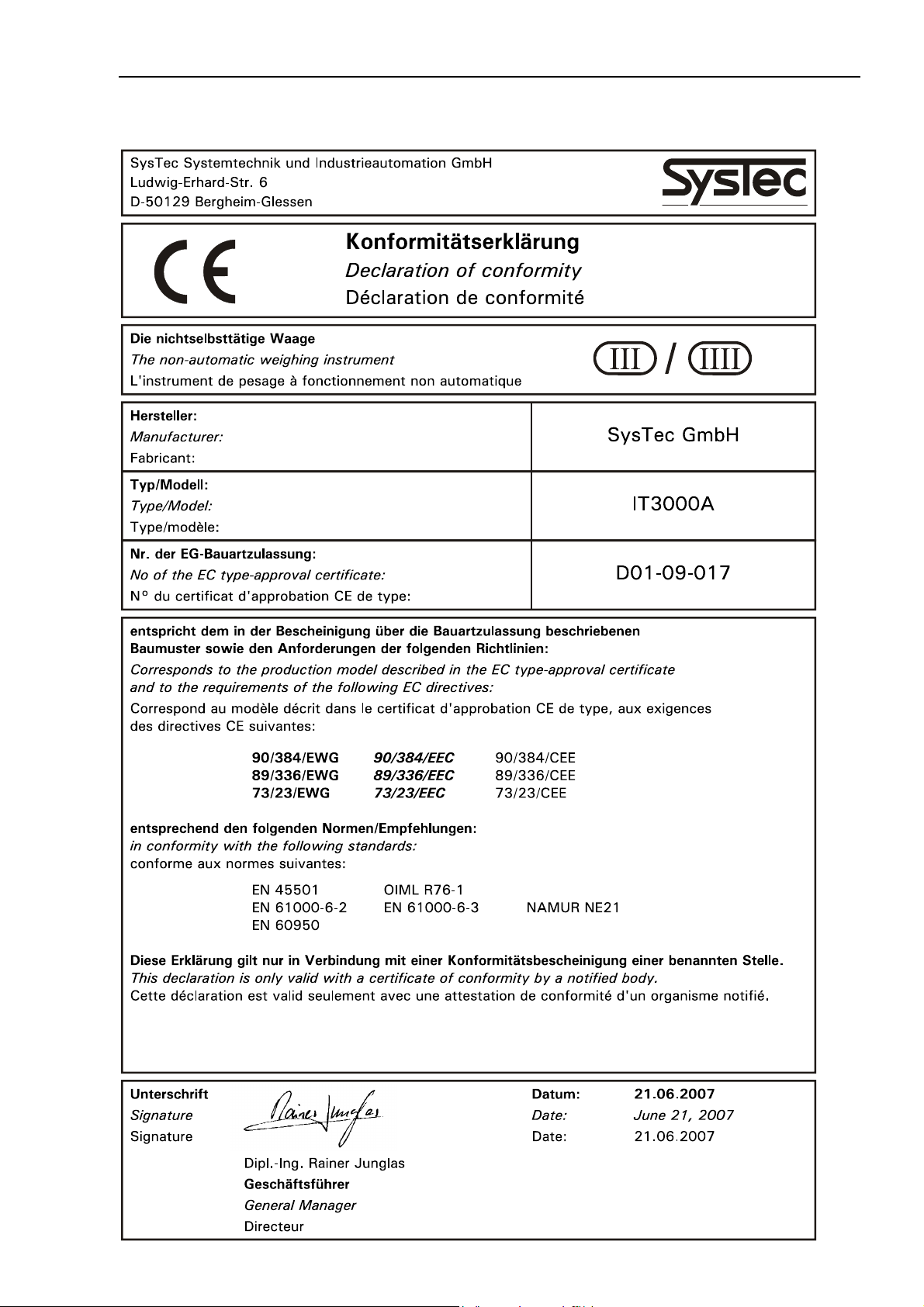
1.4 Declaration Of Conformity

12 Technical Manual IT3000A Rev. 4
2 System Description
The IT3000A is a general purpose weighing terminal for use in a variety of applications such as data
logging, data capturing, parts counting and filling. Depending on the chosen scale interface (ADM or
Dual-ADM) and the selected operating mode, either one or two analog understructures with a total of
up to 16 strain gauge loadcells with an impedance of 350 Ω each can be connected.
The operating modes BASIC, COUNT and ONLINE support the connection of 2 scale bases, whereas
TRUCK, TRUCK/ONLINE, CHECK and FILL are intended for 1 scale base only.
As required for a specific application, plug-on modules for 1 or 2 serial interfaces and 1 module with
2 parallel I/Os or 1 analog output can be added. The integrated clock / RAM module (512kB) provides
powerfail safe date and time function, scale error log, and storage for up to 1000,000 records in a
data archive, 99 first weights (operating mode TRUCK), as well as 9 tare values per scale, 9
reference weights (operating mode COUNT) and 9 product parameters (operating mode FILL).
Power supply through the built-in power supply unit is either for 110 - 240 VAC or 12 - 30 VDC.
Cables of all external components are connected at screw terminals.
Weight and additional information is indicated on a back-lit 20-character LCD, height of characters
14mm. Operation and data entry is made via a sealed membrane keyboard with tactile feedback.
Operation, sequence and printout can be configured for a specific application. All entries required for
the configuration can be made through the keyboard of the terminal. As an alternative, a
comprehensive PC program for configuration and archiving is available.
Instead of operating the terminal locally via keyboard and display, full remote control is possible from
a PC. In applications legal for trade data can also be stored in an approved data archive on the PC's
harddisk.
2.1 Construction
IT3000A is incorporated in a stainless steel housing, protected to IP65, for wall-mount or desk-top
installation. As option, a panel-mount version is available. All cable connections are made at the rear
of the housing through tight cable glands.
See section 'Dimensions' for details.
Technical Manual IT3000A Rev. 4 13
3 Description Of Components
3.1 Main Module CPU3000A
The CPU3000A module is the core of the IT3000A weighing terminal. It contains the microcontroller
with data and program memory. Sockets are provided for the scale interface board ADM (1 scale
base) or Dual-ADM (two scale bases) and the optional installation of 2 serial interfaces (SIM) and 2
parallel I/Os (PIM) or 1 analog output (DAU).
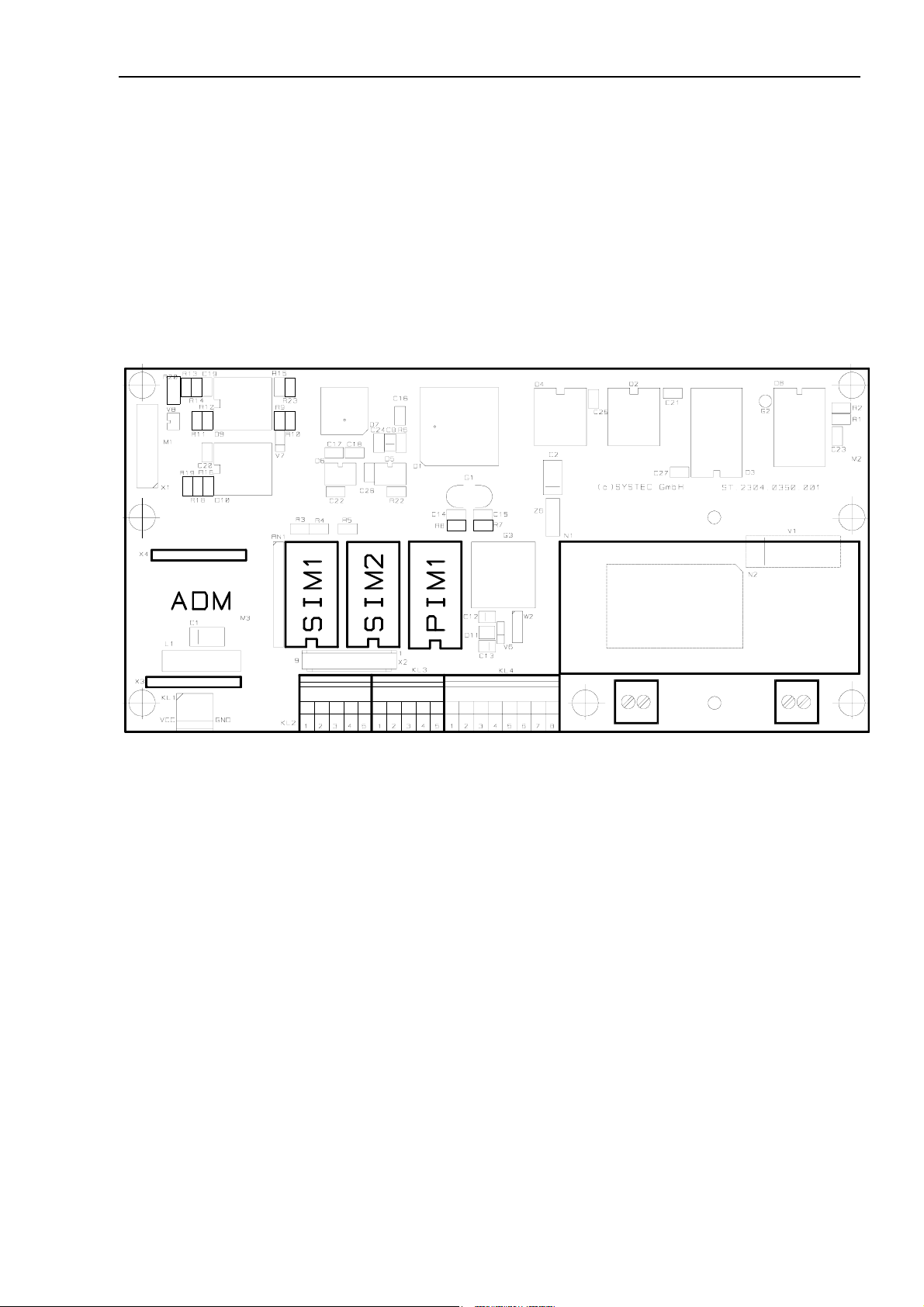
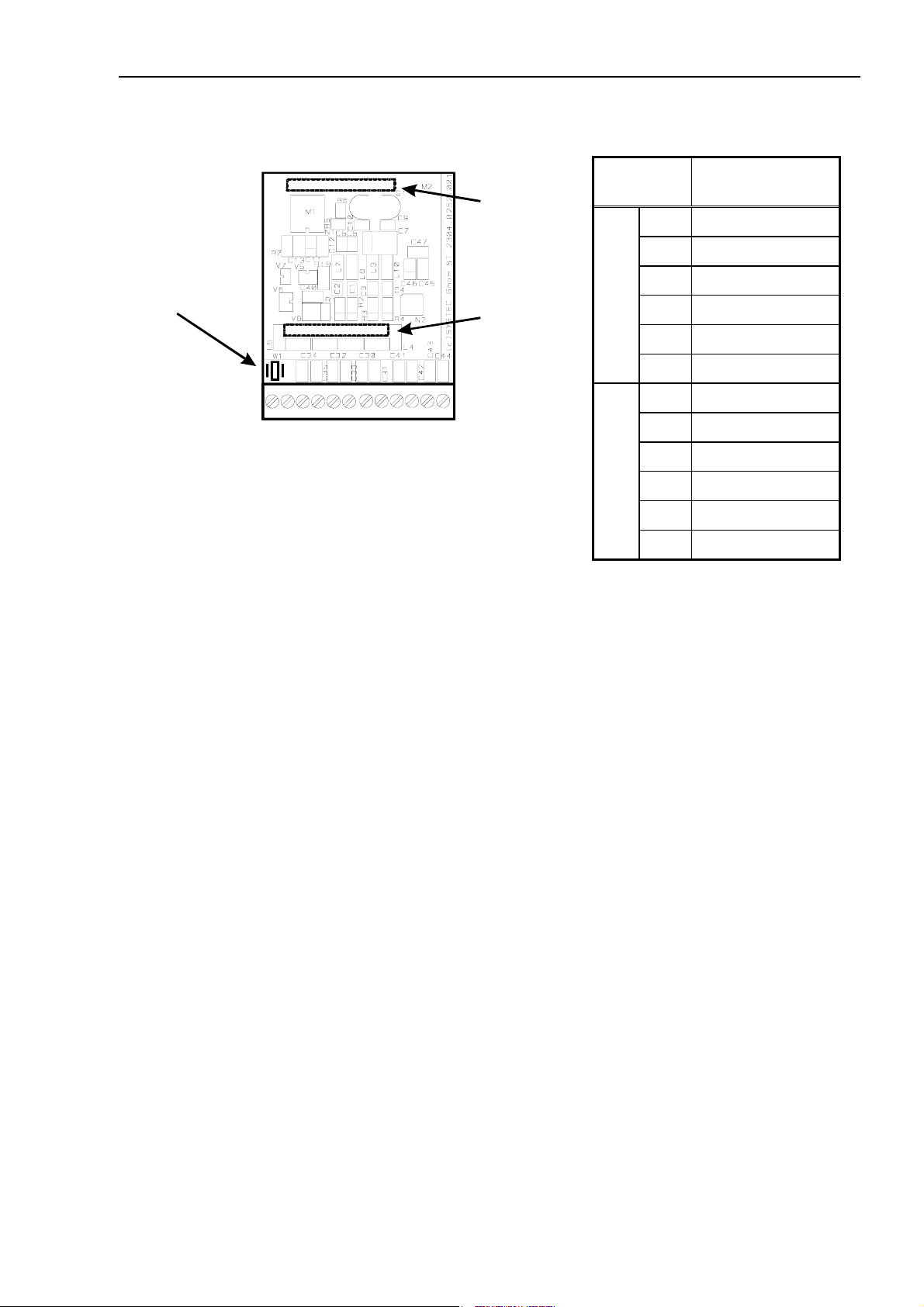
Layout of components on CPU3000A main module:
Power supply unit
Socket for
ADM / Dual-ADM
scale interface
Terminal KL2
interface COM1
Terminal KL3
interface COM2
Terminal KL4
digital inputs/
outputs
Terminal KL6
PE
Terminal KL5
power supply
3.2 Display
To indicate the weight, status information and operator prompts a back-lit 20-character LCD display
is used. The height of characters is 14mm, each character is formed by a matrix of 5x7 dots. The
display is connected at the 16-pin connector X1 on the main module.
By means of the selectable powersave function, backlighting can be switched off after time when the
the terminal is not in use.
14 Technical Manual IT3000A Rev. 4
z
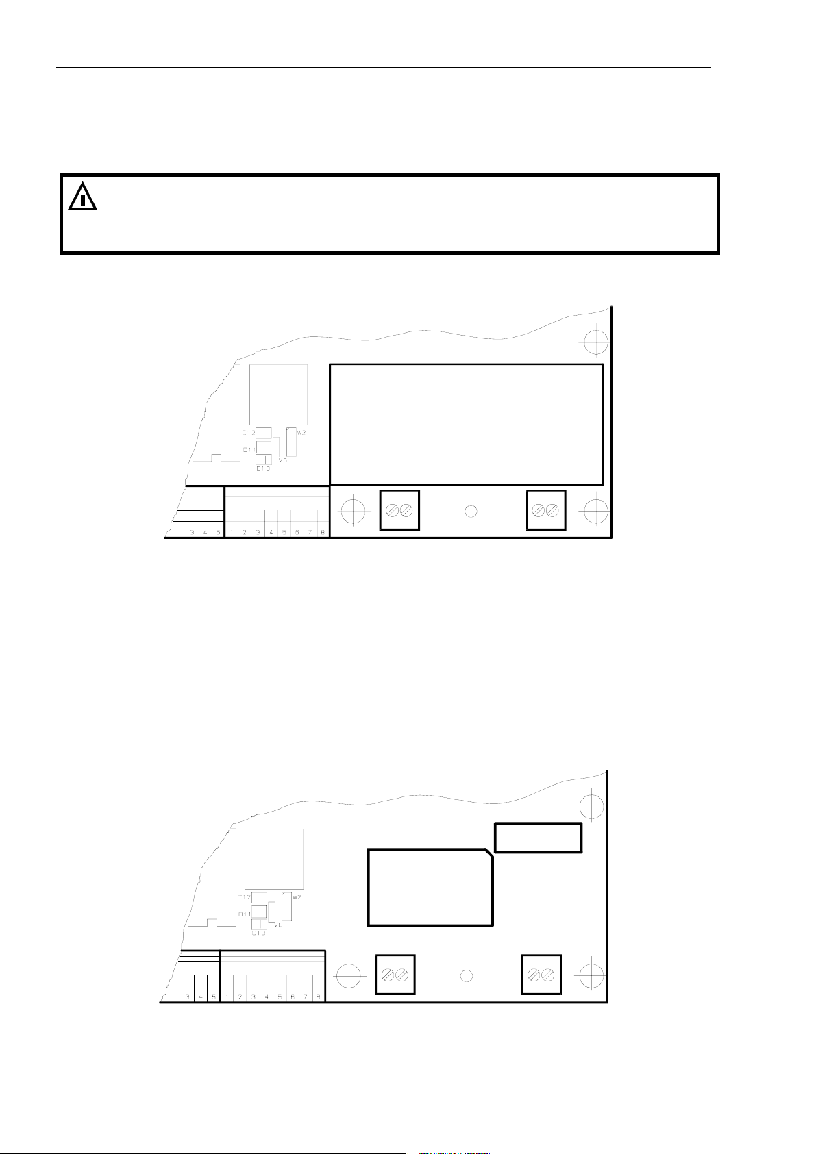
3.3 Power Supply 110 - 240 VAC
The auto sensing switching mode power supply unit operates on an input voltage ranging from 110
Volt (–15%) to 240 Volt (+10%), 50/60 Hz. The output rating is 1A at 5VDC.
W A R N I N G
Parts of the power supply unit are directly connected to dangerously high voltages!
A defective power supply unit can only be replaced. Disconnect all power to the instrument
before servicing!
Position of soldering pins for input and output voltages:
Power supply unit
PE
Terminal KL6
110 V (–15%) to 240 V (+10%),
The power supply has a fused input (2A slow blow).
L1 N
Terminal KL5
50/60H
3.4 Power Supply 12 - 30 VDC
Alternatively, IT3000A is available in a version that operates on 12 V (–15%) to 30 VDC (+10%).
For this version a DC/DC converter is installed on the main module instead of the AC power supply.
The DC version has a fused input (1A slow blow). The output rating of the converter is 5VDC at
600mA.
F1 / 1A
DC/DC
converter
+V 0V
Terminal KL5
12 - 30 VDC
Technical Manual IT3000A Rev. 4 15
4 Installation
4.1 Safety Advice
W A R N I N G
Disconnect all power to the instrument and/or unplug line cord prior to opening the housing!
Failure to observe this precaution could result in bodily injury!
Notes:
• Transport and storage of electronic components such as boards, EPROMs, etc. must only be
made in suitable anti-static ESD bags or cases.
• Shielding measures for the connection of cables must absolutely be adhered to. Insufficient
shielding may cause interference and could result in malfunction of the instrument.
4.2 Setup Of The Instrument
Ambient temperature for operating the unit may range from –10°C to +40°C, at a maximum of
95% relative humidity, without condensation. Exposure to direct sunshine should be avoided.
For wall-mount applications the terminal can be fixed at the wall first, the connection cables can be
fitted later with the lid of the housing removed.
4.3 Opening Of The Housing
To open the housing a size 7mm wrench is required. Please make sure that cables running from the
various modules to display and keyboard are not torn off or damaged when lid is removed.
4.4 Connection Of Cables
All cables are led into the housing through cable glands. Required size of wrenches: PG9 → 17mm;
PG11→ 20mm.
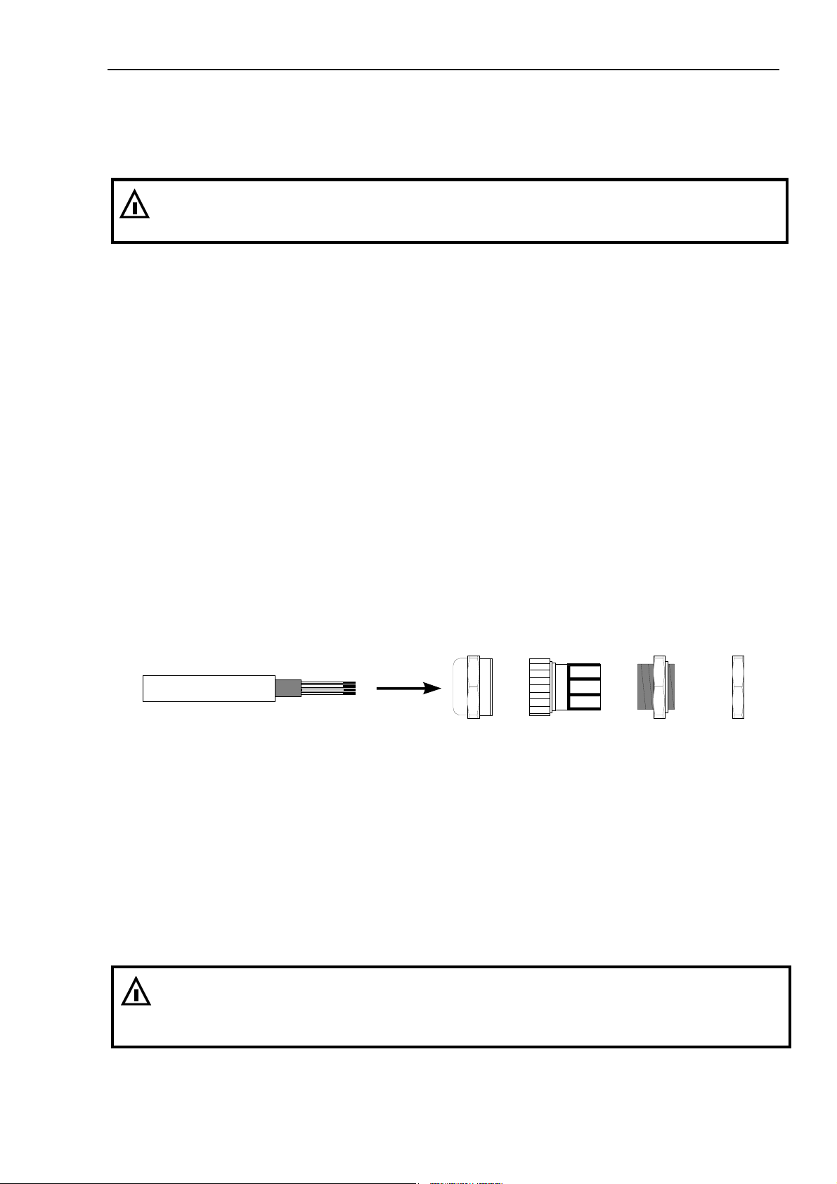
Cable jacket Shield Wires Compression nut Plastic insert Bushing Counter nut
Cable connection through cable glands:
1. Slide compression nut over cable jacket;
2. Slide plastic insert (retainer) over cable jacket until inner end is aligned with cut end of jacket;
3. Unravel shield, bend over retainer and push into retaining comb. Cut wires of shield to length of
comb, avoid protruding wires;
4. Insert retainer with cable into bushing;
5. Screw compression nut onto bushing and use wrench to tighten securely.
W A R N I N G
Cut cable ends as short as possible and make sure that they cannot touch any parts (mains
cable, power supply) conducting mains voltage!
Use cable ends on stranded cables and avoid protruding wires!
16 Technical Manual IT3000A Rev. 4
4.5 Connection Of Scale
4.5.1 Analog Understructures And Loadcells
Connection of weighing platforms and loadcells to the IT3000A terminal is made via an ADM or DualADM scale interface as specified below:
• 1 scale base (ADM), 2 scale bases in switching mode (Dual-ADM)
• Max. 16 strain gauge loadcells 350 Ω each
• Overall impedance 21.5 Ω ...4500 Ω
• W&M approved resolution of 6000d at a max. preload of 80%, internal resolution
524,000d
• Smallest permissible input signal for approved applications: 0.33 µV / e
• Update rate 50 updates / second
• Loadcell excitation: 5 V ±5% (gated power supply).
4.5.2 Connection Of 1 Scale Base Via ADM
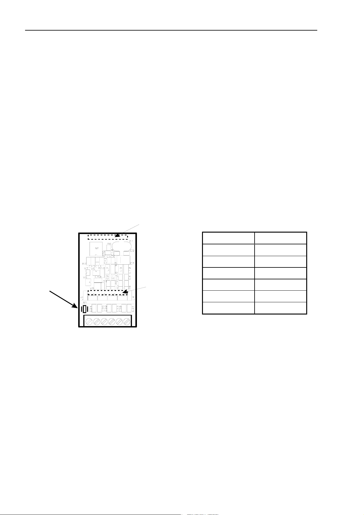
Terminal assignment on ADM module:
X2
Connection
to X4 on
CPU3000A
Terminal KL1 Assignment
1 + Excitation
Jumper W1
for protection of
calibration data
1
Terminal KL1
scale base with analog
loadcell(s)
Connection of 4-wire loadcell:
To connect loadcells without sense lines (4-wire connection), two jump leads must be connected at
terminal strip KL1 between terminal 1 and 3, and between terminal 2 and 4.
6
X1
Connection
to X3 on
CPU3000A
2 – Excitation
3 + Sense
4 – Sense
5 + Signal
6 – Signal
Technical Manual IT3000A Rev. 4 17
4.5.3 Connection Of 2 Scale Bases Via Dual-ADM
Terminal assignment on Dual-ADM module
Jumper W1
for protection of
calibration data
1166W1 W2
X2
Connection
to X4 on
CPU3000A
X1
Connection
to X3 on
CPU3000A
Terminal
KL1
1 W1 + Excitation
2 W1 – Excitation
3 W1 + Sense
W1
4 W1 – Sense
5 W1 + Signal
6 W1 – Signal
1 W2 + Excitation
Assignment
Terminal KL1
connection for analog
loadcells scale 1 and 2
Connection of 4-wire loadcell:
W2
2 W2 – Excitation
3 W2 + Sense
4 W2 – Sense
5 W2 + Signal
6 W2 – Signal
To connect loadcells without sense lines (4-wire connection), two jump leads each must be
connected at terminal strip KL1 between terminal 1 and 3 as well as 2 and 4 (scale 1 and 2).
For operation with two scales please note:
Connection of 2 scale bases is only supported by the operating modes BASIC, COUNT,
BASIC/COUNT and ONLINE.
The Dual-ADM module has one A/D converter which is either connected to scale 1 or scale 2 and
which does not permit reading of the two scales in parallel (switching mode only). A summing mode
is not possible. On switching from one scale to the other, new measuring values are determined for
digital filtering and the motion detector, thus it takes approx. 1 sec after switching until a stable
weight can be displayed.
The Dual-ADM module provides hardware detection to tell the operating system that now two scales
are connected. Only then the calibration routines for the second scale can be called up.
4.5.4 Connection Cables
For the installation of connection cables for analog weighing platforms please follow the recommendations listed below:
• Only use suitable loadcell cable, (e.g. SysTec order-No. 10KAB211.
4 x 0.75mm² + 2 x 1mm², shielded,)
Nominal voltage of cable ≥250V.
Unsuitable loadcell cable may affect accuracy.
• The shield of the loadcell cable must be connected all around the cable in the cable gland of
the weighing terminal (see also chapter 'Installation' / 'Connection Of Cables'). If an extension
of the loadcell cable is required use only metal junction boxes and cable glands. The shield on
both sides must be connected in the same way as at the terminal. Loadcells and/or weighing
platforms, junction boxes and the terminal must be included in the potential equalization of
the components of a weighing system. Depending on the situation on site this may require
the installation of a separate earth lead of appropriate diameter (e.g. 16mm²) in parallel to the
loadcell cable.
18 Technical Manual IT3000A Rev. 4
• Distance between loadcell cables and power lines: ≥0.5m. Loadcell cables to be installed in
grounded metal conduits, metal hoses or metal cable trays.
• Maximum length of connection cable between weighing platform and IT3000A: 200m
• If tension load is applied to loadcells instead of compression load, connection for +Signal and
–Signal must be switched.
4.5.5 Multiple-Range Scale
Calibration is possible as Single, Dual or Triple Range Scale. The different ranges have different
capacities and scale intervals.
Example: Triple Range Scale with a resolution of 3000 increments for each range:
First range: 0 – 1500kg / 0.5kg
Second range: 0 – 3000kg / 1.0kg
Third range: 0 – 6000kg / 2.0kg
When a Multiple Range Scale is loaded, the scale display changes automatically from a lower to a
higher range. During unloading of the scale, the scale display remains in the higher range. If the scale
was tared (weighing in net mode), on return to gross zero the tare is only cleared when the tare key
is pressed. Only after clearing the tare, the display returns to gross mode and switches back to the
smallest range.
Automatic switching back to the smallest range on reaching zero is only carried out if the scale was
not tared (weighing in gross mode).
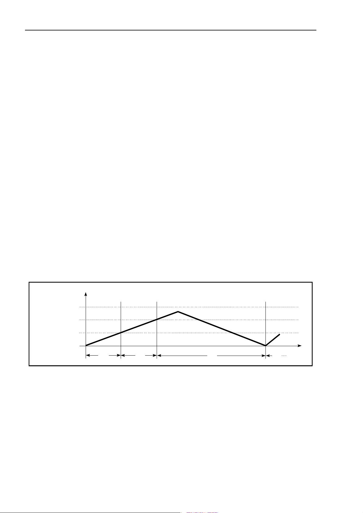
Example of a weight curve for loading and unloading a Multiple Range Scale showing the weight and
the displayed scale interval:
Gross Weight/kg
6000
3000
1500
0
Scale Interval/kg:
0.5 1.0 2.0
0.5
t
When the scale is loaded further after it was tared, the tare weight is rounded automatically to the
next scale interval as soon as the display is switched from one range to the next.
The Multiple Range Scale provides weighing of light and heavy loads on the same scale with a high
degree of accuracy, since each range has a resolution -for instance- of 3000d, inexpensive loadcells
can be used.
For the configuration of a Multiple Range scale all ranges and scale intervals can be chosen freely,
however, the maximum resolution of the loadcells (e.g. 3000d) must not be exceeded in any of the
chosen ranges.
Technical Manual IT3000A Rev. 4 19
4.5.6 Multi-Interval Scale
A Single Range Scale can be configured as Multi-Interval Scale with two or three different interval
ranges.
Example for a Triple Interval Scale:
First interval range: 0kg – 1500kg / 0.5kg
Second interval range: 1500kg – 3000kg / 1.0kg
Third interval range: 3000kg – 6000kg / 2.0kg
The scale display changes automatically from one interval range to the next during loading and
unloading of the scale.
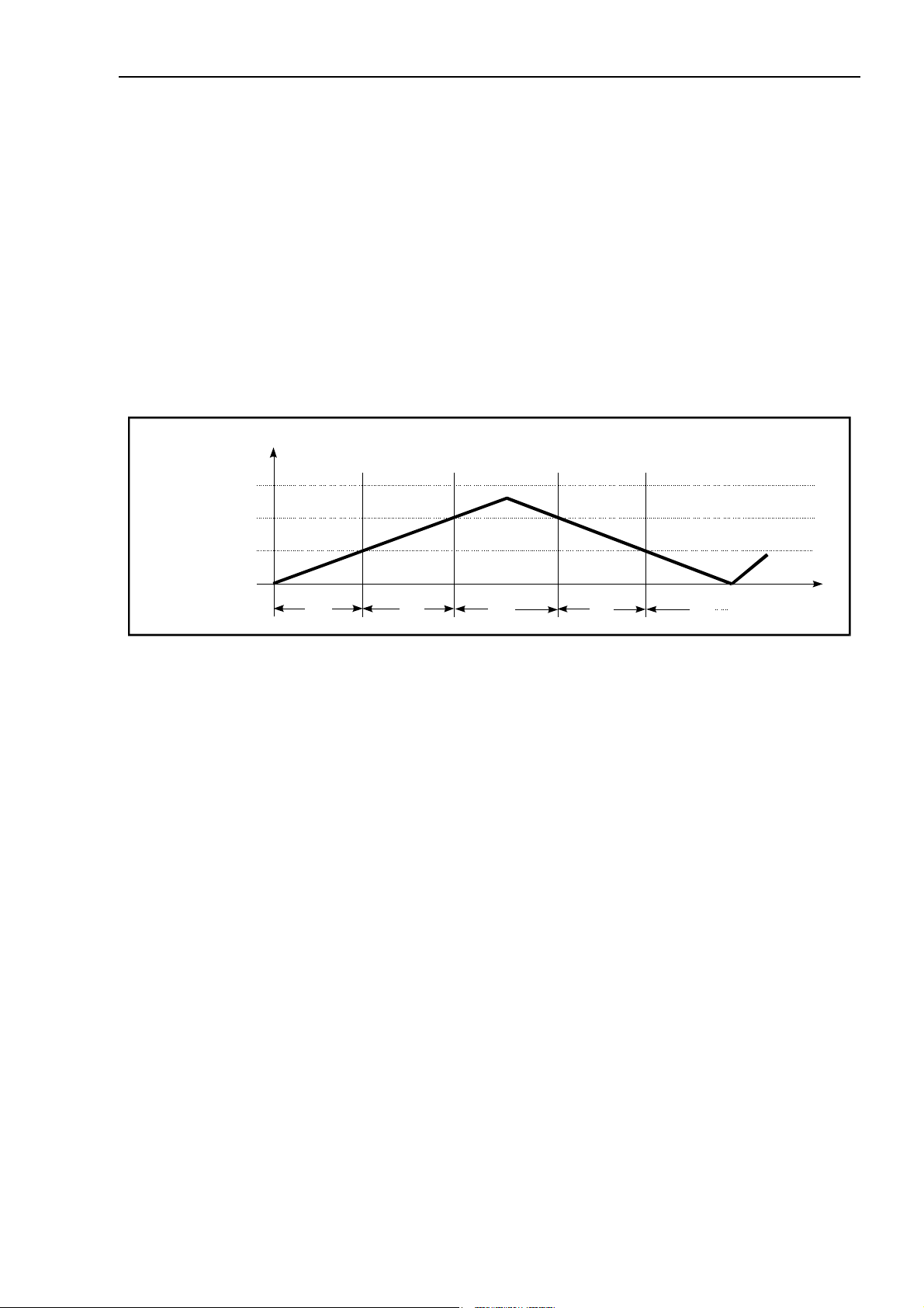
Example weight curve for loading and unloading a Multi Interval Scale showing the weight and the
scale interval displayed:
Net Weight/kg
6000
3000
1500
0
Scale Interval/kg:
0.5 1.0 2.0
1.0
0.5
t
After taring the scale, the scale display shows the net weight with the smallest scale interval. Small
weights are shown with the highest accuracy, even when the scale is already loaded to a higher
weighing range. Restriction: The max. permitted manually entered tare weight must not exceed the
weight of the range with the smallest interval.
For the configuration of a Multi-Interval scale all ranges and scale intervals can be chosen freely.

20 Technical Manual IT3000A Rev. 4
4.5.7 Adaptation To Scale Environment
The following parameters can be set to obtain optimum weighing results:
• Motion window size and number of measurments for motion detector
• Filter strength of the digital filter for unstable scales
• Auto Zero Range for Auto Zero Function
• Pushbutton Zero Range for Zero-key
• Power Up Zero Range
• Overload Threshold for display blanking.
4.5.8 Setting Of Geo Value
Before calibrating the scale, the Geo Value must be entered, e.g. Great Britain = 21 (see also chapter
Geo Values). If the scale is calibrated at one location and moved to another location later, it is
sufficient to re-enter the Geo Value of the new location.
4.5.9 Weights & Measures Approved Applications
The highest W&M certified resolution (Scale Capacity / Scale Interval) is 6000 increments (with a
max. of 80% deadload).
W&M approved installations require parameter setting in the group 'Adaptation' as follows:
• Motion Window: 0.5d
• Motion Counter: ≥7
• Auto Zero Range: 0.5d
• Pushbutton Zero: ±2%
• Power Up Zero: ±2% or ±10% *)
• Overload: max. 9 d
*) Depending on the application, also the setting 'Off' may be acceptable, e.g. for hopper
scales.
Under menu item 'W&M Info' the conformity of settings with W&M requirements can be checked.
The scale settings are stored in an EEPROM and secured with the jumper W1 which can be sealed by
Weights & Measures with thread and lead seal to prevent unauthorized modification.
Technical Manual IT3000A Rev. 4 21
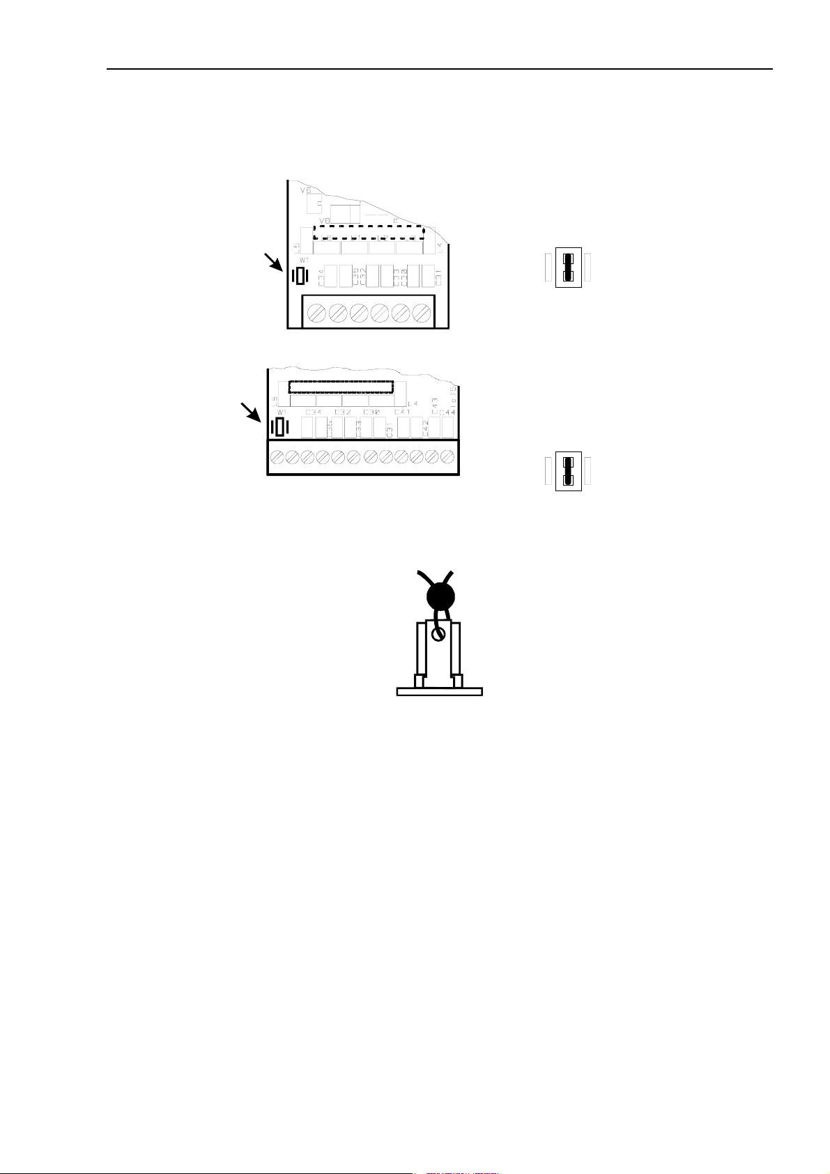
4.5.10 Securing Scale Parameters
The scale parameters are stored in EEPROM and secured with the jumper W1:
ADM
Calibration data secured
W1
1
W1
1
W&M approved applications require that the calibration parameters be protected against unauthorized
modifications. To that effect the jumper can be sealed with thread and lead seal.
6
Dual-ADM
Calibration data of both
scales secured
12
For a description of the scale calibration refer to the respective chapter.
22 Technical Manual IT3000A Rev. 4
4.6 Serial Interfaces
The serial interfaces of the IT3000A terminal can be configured individually by means of plug-on
driver modules as:
RS232 or RS485 2-wire or RS485 4-wire or RS485 2/4-wire optoisolated or 20mA CL (passive).
By default, the interfaces are assigned to: COM1 → PC/EDP, COM2 → printer. The assignment can
be changed in Service Mode to connect other devices such as remote display and reference scale.
4.6.1 Connection Of Serial Interfaces
Connection of serial interfaces on the main module:
> RS232
Terminal strip
KL2
Terminal assignment interface #1 and #2:
Terminal strip KL2: serial interface #1 (COM1)
Terminal strip KL3: serial interface #2 (COM2)
Terminal # RS232 20mA RS485
1 TxD TXIN TxD+ TxD+ / RxD+
2 RTS TXOUT TxD– TxD– / RxD–
3 RxD RXIN RxD+ —
4 CTS RXOUT RxD– —
5 Gnd — — —
Terminal strip
KL3
4-wire
Insert with
notch pointing
to bottom!
RS485
2-wire
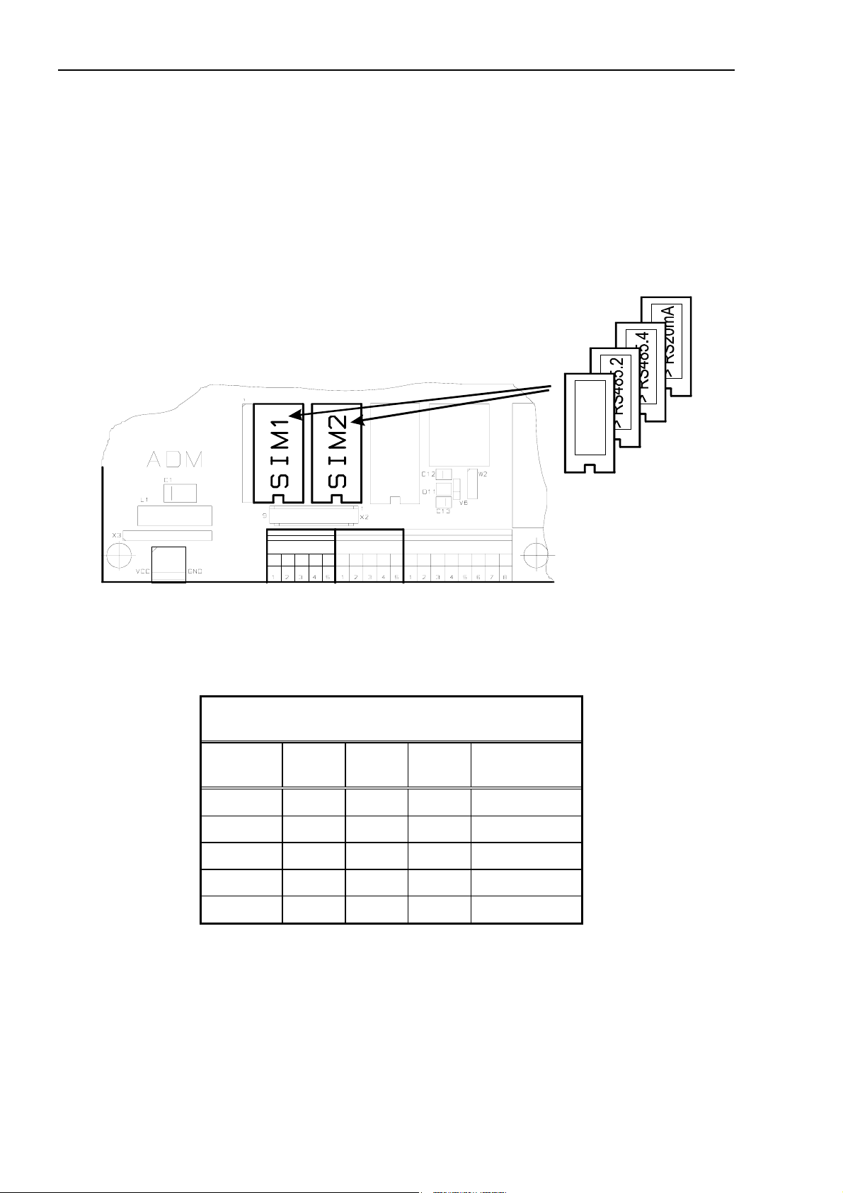
4.6.2 SIM RS485.OPTO
The SIM RS485.OPTO interface driver is autosensing and provides both, 2-wire and 4-wire
communication.
Please note: This module cannot be inserted in socket SIM 1 when a Dual-ADM board is installed.
Technical Manual IT3000A Rev. 4 23
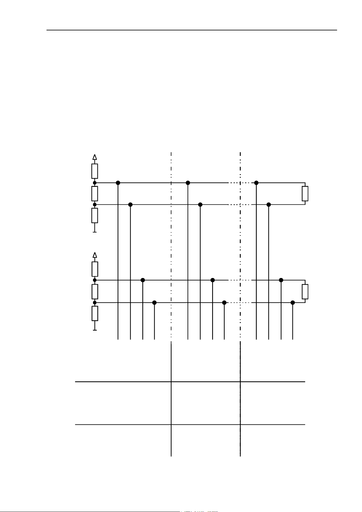
4.6.3 RS485 Network
Terminal assignment: Some manufacturers of components with RS485 interface do not refer to the
terminals TX+ and RX+ as 'A', but 'B' instead (correspondingly, the terminals TX- and RX- are not
referred to as 'B', but 'A').
Termination resistors: In order to prevent reflection (baud rate 19200 Baud or higher, and/or cable
longer than 20m) it is recommended to install termination resistors R
cable. The characteristic impedance of the cable should be approx. 150 Ω.
Pull-up / pull-down resistors: When termination resistors are used, also 390 Ω pull-up and pull-down
resistors must be installed at the master (see also following schematic).
RS 485 network with termination-, pull-up- and pull-down- resistors
V
CC
390
Ω
150
Ω
Term = 150 Ω on both ends of the
150
Ω
390
390
150
390
RS485 4-wire
Ω
Gnd
V
CC
Ω
Ω
Ω
Gnd
−
TxB (Tx )
TxA (Tx+)
−
RxA (Rx+)
RxB (Rx )
−
RxA (Rx+)
RxB (Rx )
−
TxA (Tx+)
TxB (Tx )
RxA (Rx+)
150
Ω
−
RxB (Rx )
−
TxA (Tx+)
TxB (Tx )
RS485 2-wire
A (Tx+ / Rx+)
Master (e.g. PC, PLC or
Process Control System)
Participant
A (Tx+ / Rx+)
Slave 1
− / −
B (Tx Rx )
− / −
A (Tx+ / Rx+)
B (Tx Rx )
Slave n
(Weighing Terminal IT)
− / −
B (Tx Rx )
(Weighing Terminal IT)
24 Technical Manual IT3000A Rev. 4
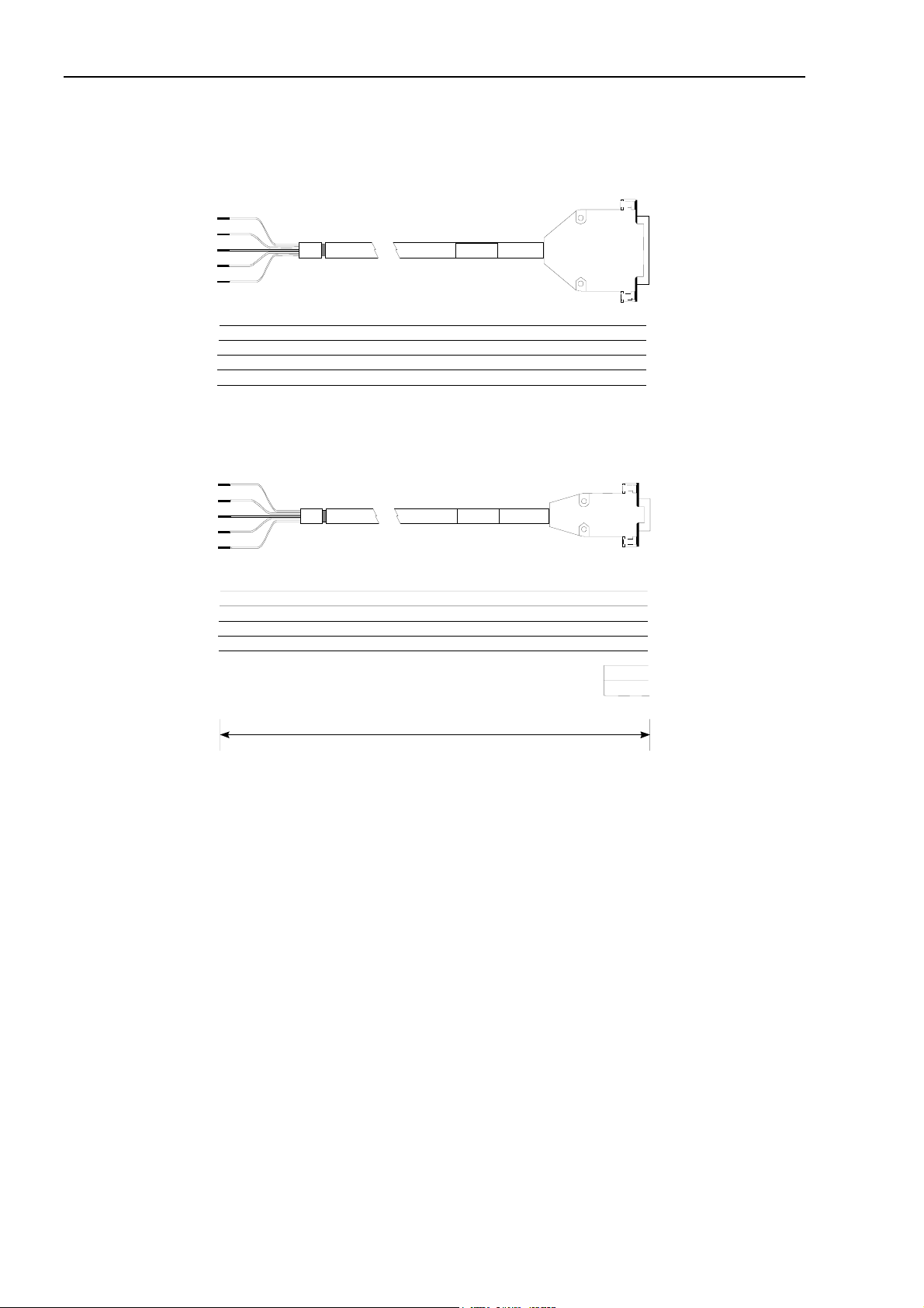
4.6.4 Cables For Serial Interfaces
Standard cables for serial interfaces:
IT3000
TxD 1
RTS 2
RxD 3
CTS 4
Gnd 5
IT3000
TxD 1
RTS 2
RxD 3
CTS 4
Gnd 5
RS232 Printer Cable with 25-pin DSUB connector
Art.-No. 10KAB200
green
yellow
brown
white
gray
RS232 PC Cable with 9-pin male DSUB connector
Art.-No. 10KAB202
green
yellow
brown
white
gray
male
Printer
3 RxD
5 CTS
2 TxD
20 DTR
7 Gnd
PC
2 RxD
8 CTS
3 TxD
7 RTS
5 Gnd
1
4
6
approx. 3m
For the installation of connection cables for serial interfaces please follow the recommendations listed
below:
• Install data cables to prevent capacitive or inductive interference from other cables, machines
and/or electrical devices that could interrupt data transmission and lead to loss of data. If
fluctuation of the earth potential is experienced, this can cause an equalization current flowing
over the shield. In this case a separate earth lead of appropriate diameter for potential equalization
is required.
• Non-factory made cables must comply with the following specification:
3 times twisted pair plus screen, e.g. LIYCY 3 x 2 x 0.14mm² or LIYCY 3 x 2 x 0.25mm²,
For maximum suppression of interference, shield should be grounded on both sides.
Resistance ≤ 125 Ω/km
2
Gauge ≥0.14 mm
up to 200m, ≥0.25 mm2 up to 1200m
Capacitance ≤ 130 nF/km
Length RS232 max. 15m
Length RS485 max. 1200m
Impedance RS485 approx. 150 Ω
Nominal voltage ≥ 250V
Technical Manual IT3000A Rev. 4 25
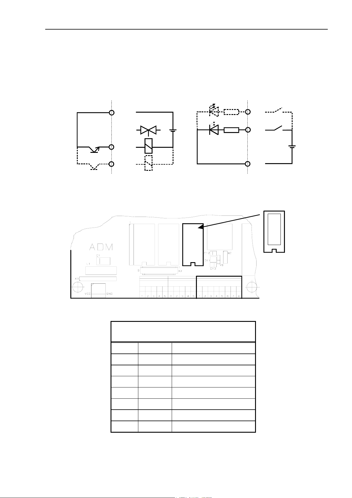
4.7 Connection Of Parallel I/Os
The parallel input/outputs on the CPU3000A can be activated by inserting a plug-on module. The
module provides drivers for two opto-isolated inputs and two opto-isolated outputs.
Rating of outputs: 24VDC, 100mA; rating of inputs: 7mA @ 24VDC.
Principal schematics:
OUT+
+
-
OUT0
OUT1
Parallel output Parallel input
Position and assignment of parallel inputs/outputs on CPU3000A board:
Ri
3K3
IN1
IN0
IN–
PIM
+
-
> PIM
Insert with
notch pointing
to bottom!
Terminal strip KL4
Terminal assignment:
Terminal strip KL4: parallel inputs and outputs
1 OV
2 +10V for external switches only!
3 IN0
4 IN1
5 In– for IN0 - IN1
6 OUT0
7 OUT1
8 OUT+ for OUT0 - OUT1
Note: The internal 10VDC supply (KL4, terminal 2) may be used to connect switches and push
buttons to the digital inputs (15mA max.). The step-up regulator that generates this voltage is short
circuit proof for 1 sec max. External devices connected to the digital outputs must always be
supplied from an external 24VDC power supply.

26 Technical Manual IT3000A Rev. 4
4.8 Connection Of 8-Bit Analog Output DAU
For the output of gross or net weight as analog signal a plug-on module (DAU) can be inserted
instead of a parallel driver module. The output signal has a resolution of 8 bit (256 steps, limits of
operating error = ±4%). The input of the connected device must be electrically isolated and must
not be connected to ground.
Digital inputs/outputs via PIM module and analog output are not possible at the same time.
Position and assignment of analog output on CPU3000A board:
> DAU
PIM1
Insert w ith
notch pointing
to bott om!
Terminal strip KL4
The analog output module can be configured to current output (factory setting) or to voltage output
via solder bridge. Two more solder bridges serve to select internal or external power supply.
Position of solder bridges on DAU:
W1
W3
1
Configuration of DAU via solder bridges W1, W2 and W3.
W1 closed / W2 open W1 open / W2 closed
W3 open Current output 0 - 20 mA
internal power supply
maximum load: 120 Ω
W2
Current output 0 - 20 mA
external power supply 15 - 30 V
maximum load: 750 Ω
W3 closed not allowed! Voltage output 0 - 10 V
Note: Only bridge W1 or W2 may be closed!
external power supply 15 - 30 V
min. input resistance 3.3 kΩ

Technical Manual IT3000A Rev. 4 27
If the analog driver is configured accordingly, the settings in Service Mode, group 'General' 0 - 20
mA or 4 - 20 mA also apply to the voltage output 0 - 10 V or 2 - 10 V.
Terminal assignment:
Terminal strip KL4: analog output DAU
1 must remain free
2 must remain free
3 Uext voltage input when external supply 15 - 30 V is used
4 Gnd ground for exernal supply and voltage output
5 must remain free
6 I– current output
7 I+/U+ current or voltage output
8 must remain free
Example for current output 0 - 20 mA, supply of loop from IT3000A:
3
4
W1 closed
W2
W3 open
> DAU
open
IT3000 KL4
7
+
120 max.
–
6
Example for current output 0 - 20 mA, supply of loop from external power supply:
W1 open
W2 closed
W3 open
> DAU
Gnd
IT3000 KL4
3
4
7
+
–
6
+15 - 30 VDC
external power supply
potential free
0 V
750 max.
Example for voltage output 0 - 10 V, external power supply:
3
4
W1 open
W2 closed
W3 closed
> DAU
Gnd
IT3000 KL4
7
+
6
+15 - 30 VDC
external power supply
potential free
0 V
3.3 k min.
28 Technical Manual IT3000A Rev. 4
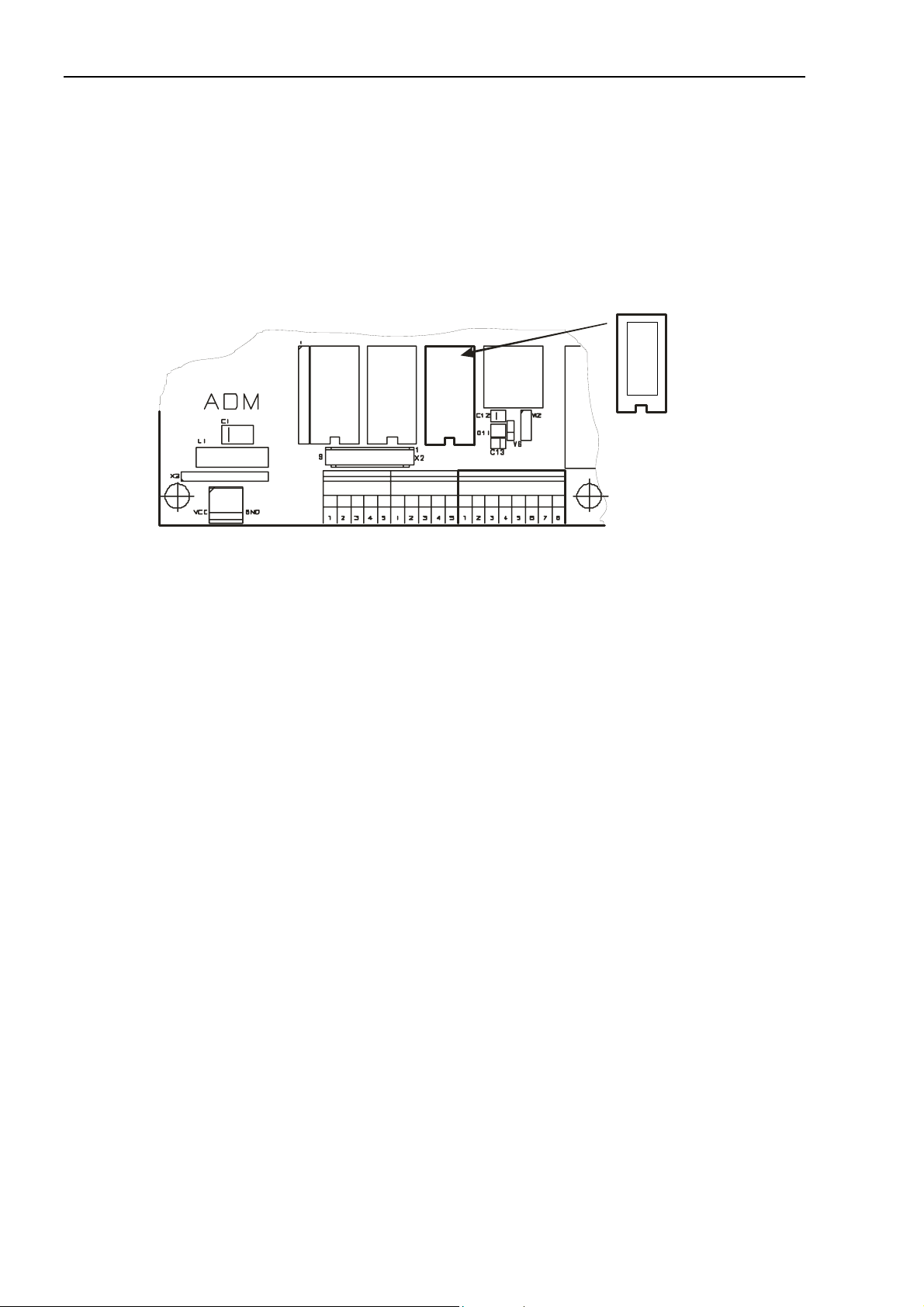
4.9 Connection Of 15-Bit Analog Output DAU15
For the output of gross or net weight as analog 15-bit signal a plug-on module (DAU15) can be
inserted instead of a parallel driver module in socket PIM1. The output signal has a resolution of 15
bit (32768 steps). The module can be configured in group 'DAU' of the Service Mode to 0/2 - 10V or
0/4 - 20mA. The output of the DAU15 module is active and potential free.
Digital inputs/outputs via PIM module and analog output are not possible at the same time.
Position and assignment of analog output DAU15 on CPU3000A board:
> DAU 15
PIM1
Insert w ith
notch pointing
to bott om!
Terminal strip KL4
Technical Manual IT3000A Rev. 4 29
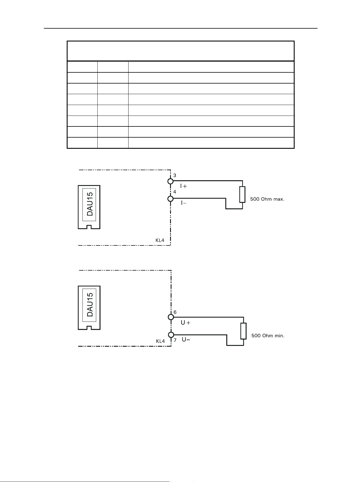
Terminal assignment:
Terminal strip KL4: analog output DAU15
1
2
3 I+ Current output 0/4 - 20mA
4 I– Gnd for current output 0/4 - 20mA
5
6 U+ Voltage output 0/2 - 10V
7 U– Gnd for voltage output 0/2 - 10V
8
Example for current output 0/4 - 20 mA:
Example for voltage output 0/2 - 10 V:

30 Technical Manual IT3000A Rev. 4
4.10 Mains Connection
Before connecting the instrument to power please note:
• Input voltage of the instrument must comply with local mains supply. Factory setting: 110 - 240
V; 50/60Hz, line cord with safety plug firmly connected. The DC version does not have a line
cord and is intended for connection to 12 V to 30V DC.
• Install mains supply for the instrument separate from supply for machines and equipment
generating noise and/or interference (motors, relays, heatings, etc.). Even short spikes and/or
drop-outs may affect the correct function of the instrument and result in defects. If problems of
that nature are encountered, the installation of a voltage stabilizer or an uninterruptable power
supply unit (UPS) may help to overcome the difficulties.
• IT3000A does not have a mains switch and is operational after connection to the mains supply.
Connection to the mains supply is made via the factory installed line cord (length of cable 2.5m).
Make sure that wall outlet is correctly grounded (not applicable to DC version).
• If the line cord with connector is used as the means to separate the instrument from the mains,
the wall outlet must be installed close to the instrument and must be easily accessible! If a
permanently connected mains cable is used, an easily accessible separator must be included in
the supply circuit!

Technical Manual IT3000A Rev. 4 31
5 Service Mode
5.1 General
The Service Mode is a program for configuration, calibration and hardware test of the IT3000A
weighing terminal. In the configuration the operating sequence and the print format are defined. The
following sections give an introduction on how to operate the terminal via keyboard and display and
describe the individual functions of the Service Mode.
Notes:
• IT3000A and its associated equipment must be installed, adjusted and maintained by qualified
personnel only!
• Before accessing the Service Mode all peripheral devices must be installed and configured!
• Access to the Service Mode is protected by the Service Password (see also last page of this
manual).
• Inappropriate changes of Service Mode settings may lead to malfunction and errors in the
operating sequence!

32 Technical Manual IT3000A Rev. 4
5.2 Display And Keyboard
~
F
Gross or net weight or operator prompt and entry
Display line:
Symbol: Scale in gross zero range (±0.2d)
Symbol: Scale in motion
Info Scrolling forward, call up Service Mode in the initial step
Info and scale keys:
F1 – F8
Function keys:
F1 - F2
F0
Taring (Autotare), if scale is tared: clear tare
Set gross weight to zero
Press F-key and numeric key (1 - 8) subsequently to access function
defined in application program;
Switching scale 1 <-> scale 2 when two scales are connected via
Dual-ADM (in the steps defined in the application program).
Switch weight display to tenfold resolution (in the basic step of the
sequence), display falls back to normal mode after approx. 5 sec.
Clr
Numeric entry: press key once → clear entry
Alphanumeric entry: short key stroke → clear last character (can be
repeated several times to clear more than one character); hold key
down for approx. 1 sec → clear the whole entry
Special keys
↑
Return to previous program step
Numeric keypad:
↵
Confirm entry, continue with next program step
Total Display / print totals (if defined in the operating sequence and the
printout)
Entry of numeric data, confirmation 'Yes' (=1) - 'No' (=0) and entry
of alpha characters via multiple key assignment

Technical Manual IT3000A Rev. 4 33
5.2.1 Multiple Assignment Of Numeric Keypad
Where applicable in the application program, an alphanumeric entry is made by selecting the
respective character with a sequence of short keystrokes. If a key is pressed repeatedly within a
period of approx. 0.5 seconds, the display shows the other characters also assigned to this key one
after the other.
Example:
Key pressed: 5 5 5 5 5 5 5 5
Display: 5 M N O m n o 5 etc.
To enter the letter 'n' the key 5 must be pressed six times until 'n' appears on the display. If the
entry is paused for longer than 0.5 sec, the cursor moves on to the next character. If any other key is
pressed, entry continues in the position of the next character immediately.
An incorrect entry can either be corrected by deleting the last character (short key stroke on Clr-key)
or by clearing the complete entry (Clr-key pressed for longer than 0.5 sec). By pressing the Clr-key
repeatedly, it is possible to delete several characters one after the other.
5.3 Operator Prompting
The following sections describe the operating sequence of the weighing terminal with operator
prompts and the requested entries.
The contents of the terminal display is shown in a frame on the left hand side. Next to the display the
possible operator entries are listed, on the right hand side comments and explanations are shown.
Password ????
Prompts or entries that apply only under certain conditions are shown in an extra frame. The
condition is shown in bold face in the upper left hand corner of the frame.
PC not ready:
PC Not Ready !
This message is only displayed when an error occurs.
↵ -key (Enter) and ↑-key
In all program steps, unless otherwise specified, the ↵ -key (Enter) leads to the next step. Pressing
the
↑ -key leads to the previous step.
Entry of 4-character password
↑
Return to normal operation
Error message: PC is not ready for data transmission
Confirmation with Yes (1) or No (0):
A prompt, e.g. 'Save parameters? Y' can be answered by pressing 1 and the
proposed action or by pressing 0 and the
the parameters are not saved.
↵-key to reject the proposal. In this example by entering 0
↵-key to accept the

34 Technical Manual IT3000A Rev. 4
5.4 Overview
After powering the terminal up, the messages with display of program version and date and time are
displayed. By pressing the Info-key while the power up messages are displayed, the Service Mode is
called up. After that the program proceeds to the initial step.
Power up:
Version 9.99 999999
03.09.01 10:41
Application: Count
Display of deviation from calbrated zero, if enabled in Service Mode:
W1 0-Cal. 0.00
Number and date of version,
display for approx. 1.5 sec
Info Call up Service Mode
Date and time,
display for approx. 1.5 sec
Info Call up Service Mode
Selected operating mode,
display for approx. 1.5 sec
Info Call up Service Mode
Show difference between actual and calibrated zero
with tenfold resolution,
display for approx. 1.5 sec
Info Call up Service Mode
Service Mode:
Service Mode
Password ????
Servive Mode menu:
Service: Interface
Service: Format
Display for approx. 1.5 sec.
Entry of 4-character Service Password
↑
Return to normal operation
Configure interfaces;
(see chapter 'Interface Configuration')
Info Use Info-key to scroll through groups
Call up displayed group
↵
Configure operating sequence and printout;
(see chapter 'Configuration Of Data Entry And Print
Formats')

Technical Manual IT3000A Rev. 4 35
Service: General
ADM installed for connection of 1 scale:
Service: Calibrate
Dual-ADM installed for connection of 2 scales:
Service: Calibrate 1
Service: Calibrate 2
Service: Backup
Enter setup parameters (language, format of date,
Calibrate scale;
Calibrate scale 1;
Calibrate scale 2;
Backup of data on PC;
basic sequence, field 33 - 34);
(see chapter 'Entry Of Parameters')
(see chapter 'Calbrate Scale')
(see chapter 'Calbrate Scale')
(see chapter 'Calbrate Scale')
(see chapter 'Backup')
Service: Restore
Service: Test
Service: DAU
Service: Reset
Exit Service Mode:
Saving...
Restore data from PC;
(see chapter 'Restore')
Test hardware;
(see chapter 'Harware Test')
Configure analog output;
(see chapter 'Entry Of Parameters For Analog Output')
Restore factory settings;
(see chapter 'Reset')
Exit Service Mode and store changes, return to normal
↑
operation

36 Technical Manual IT3000A Rev. 4
5.5 Overview Service Mode
Part 1

Technical Manual IT3000A Rev. 4 37
Part 2

38 Technical Manual IT3000A Rev. 4
6 Calibration
6.1 Entering Calibration Mode
Prior to power up the jumper W1 on the ADM or Dual-ADM module must be removed. Only with this
jumper setting can the changed parameters be saved in memory after the calibration.
ADM
Calibration released
W1
1
W1
1
Following below the individual steps of the calibration are described. Additional information is
provided in the chapter 'Scale Connection'.
6
Dual-ADM
Calibration released
12

Technical Manual IT3000A Rev. 4 39
6.2 Select Group
After entering the calibration mode, the first menu item is displayed:
ADM installed for connection of 1 scale:
Service: Calibrate
Dual-ADM installed for connection of 2 scales:
Service: Calibrate 1
Service: Calibrate 2
If jumper W1 is still in position 1 - 2:
Calibration Locked
Select Group 1-9
Calibrate scale;
Calibrate scale 1;
Calibrate scale 2;
Warning: jumper not in calibration position, parameters
↵
Enter number of group or use Info-key to select
1 Scale Parameters
cannot be saved!
Enter calibration mode without saving (e.g. to check
settings)
parameter group:
The parameter setting and calibration follows the sequence of the group numbers (1, 2, 5) as
described in the following chapters. After pressing the ↑-key in step 'Select Group 1
display shows the message:
Save Parameters? Y
2 Calibration
3 Linearization
4 Zero Adjust
5 Adaptation
6 High Resolution
7 Reset Parameters
8 Calculate Span
9 W&M Info
Info Scrolling forward
Save changes and return to menu
↑
Save parameters in EEPROM
-9', the
Info
or
1 / 0
Scrolling
Y(es): Save parameters
N(o): Ignore all changes, do not save data

40 Technical Manual IT3000A Rev. 4
If jumper W1 is still in position 1 - 2:
Error Calibr. Jumper
Error message: jumper not in calibration position,
parameters cannot be saved!
Exit calibration without saving
↵
6.3 Scale Parameters
In this group the weighing ranges, scale intervals and the scale unit are selected. The scale can be
configured as Single Range, Dual Range or Triple Range Scale. A Single Range Scale can be
configured as Multi Interval Scale with two or three different scale intervals.
1 Scale Parameters
1 Scale Parameters

Technical Manual IT3000A Rev. 4 41
Select number of scale ranges:
Single Range
Single Range: Single Range Scale with one, two or
three intervals
Dual Range: Scale with two ranges
Triple Range: Scale with three ranges
If 'Single Range' has been selected:
One Interval
If 'Single Range' and 'One Interval' has been selected:
Capacity 999999
Interval 999999
Info Scroll list
A Single Range Scale can be configured as Single- or
Multi-Interval Scale. Options:
One Interval or
Two Intervals or
Three Intervals or
Additive Tare = Single Range scale with additive tare
(not for W&M approved applications)
Info Scroll list
Single Range capacity entry (6 digits).
Example: 'Capacity 1500'
Single Range scale interval entry (6 digits).
If 'Two Intervals' or 'Three Intervals' has been
selected, entry of the smallest scale interval. (See also
chapter Multi Interval Scale).
Example: 'Interval 0.5000'
Valid entries are:
0.0001, 0.0002, 0.0005, 0.0010, 0.0020, 0.0050,
0.0100, 0.0200, 0.0500, 0.1000, 0.2000, 0.5000,
1.0000, 2.0000, 5.0000, 10.0000, 20.0000,
50.0000, 100.0000, 200.0000, 500.0000.
Incorrect entries are not accepted.
If multiple-range 'Dual Range' or multi-interval 'Two Intervals' has been selected:
High Cap. 999999
High Int. 999.9999
Low Cap. 999999
Low Int. 999.9999
Enter capacity in the higher range (6 digits).
Example: 'High Cap. 6000'
Enter interval in the higher range.
Example: 'High Int. 2.0000'
Enter capacity in the lower range (6 digits).
Example: 'Low Cap. 3000'
Enter interval in the lower range.
Example: 'Low Int. 1.0000'

42 Technical Manual IT3000A Rev. 4
If multiple-range 'Triple Range' or multi-interval 'Three Intervals' has been selected:
High Cap. 999999
High Int. 999.9999
Mid Cap. 999999
Mid Int. 999.9999
Low Cap. 999999
Low Int. 999.9999
Entry of capacity of the highest range
(6 digits)
Example: 'High Cap. 6000'
Entry of interval of the highest range
Example: 'High Int. 2.0000'
Entry of capacity of the medium range (6 digits)
Example: 'Mid Cap. 3000'
Entry of interval of the medium range (6 digits)
Example: 'Mid Int. 1.0000'
Entry of capacity of the lowest range (6 digits)
Example: 'Low Cap. 1500'
Entry of interval of the lowest scale range
Example: 'Low Int. 0.5000'
If 'Single Range' has been selected with 'Additive Tare':
Net Capacity 999999
Capacity 999999
Interval 999.9999
Unit kg
Info Scroll list
Entry of total scale capacity.
Example: 'TotalCapacity 1500'
Entry of weighing range.
Example: 'Capacity 300'
Entry of interval.
Example: 'Interval 0.1000'
Select a unit. Options: kg, g, t, lb
Return to 'Select Group'
↵

Technical Manual IT3000A Rev. 4 43
6.4 Calibration
The zero calibration and maximum load calibration are performed in this group. Instead of calibrating
to maximum load, a calibration with partial load is also possible.
The Geo Value entry permits the calibration at one place even if the scale is to be operated at a
different location. This compensates for the different forces of gravity without recalibration (not for
W&M approved applications). By means of entering the rated signals (mV/V), a scale can also be
precalibrated without test weights (see also chapter 'Precalibration').
2 Calibration
Linearization point(s) already exist:
Fixpoint active
Geo Value 99
Calibrate Zero? Y
Warning: The weight curve is already linearized, and it
might be required to delete existing linearization points
before proceeding.
Display for approx. 2 sec.
Entry of Geo Value. Enter the applicable Geo Value of
the calibration location (see also chapter Geo Values). If Geo Value of place of installation is different, that can be changed later.
Scale Zero Calibration.
Unload the scale and confirm to start the calibration.
Info Scrolling Yes: Calibrate Zero
No: Continue in step 'Zero(mV/V)'
Zero Calibration
↵
Calibrating...
Zero: 9999999
Zero(mV/V): 9999999
Clr Clear value and enter new one
Please note: If Zero calibration parameters are to be stored before the Span calibration, the Setup
must be exited at this point of the sequence (return to step 'Select Group' and answer question
'Save Parameters?' with 'Yes'. After that Group 2 can be entered again to proceed with
calibration, Zero calibration can now be skipped.
Measuring Zero signal.
Message for approx. 6 sec
Displays actual weight with tenfold resolution (for
verification).
Return to step 'Geo Value'
↑
Continue
↵
Display of rated signal
(e.g. 0.23785)
Return to step 'Select Group'
↑
Continue with Span calibration
↵

44 Technical Manual IT3000A Rev. 4
Calibrate Load? Y
Calibr.Weight 999999
Clr Clear displayed default value and enter desired
Calibrating...
Load: 9999999
Load calibration weight on scale.
For best results use the highest possible calibration
load.
Info Scrolling Yes: Calibrate Load
No: Continue in step 'Load(mV/V)'
Return to step 'Calibrate Zero?'
↑
Continue
↵
Default calibration weight
(=weighing range), 6 digits
calibration weight.
Apply load and start calibration
↵
Measuring load signal.
Message for approx. 3 sec.
Displays actual weight with tenfold resolution (for
verification).
Load(mV/V): 999999
Clr Clear value and enter new one
If the internal resolution is insufficient, an error message is displayed:
Resolution Error
To store calibration parameters exit step 'Select Group' and answer question 'Save Parameters' with
'Yes'.
Note: If changes of calibration parameters are to be ignored, setup must be exited and question 'Save
Parameters?' answered with 'No' before any other group of the calibration may be called up.
Return to step 'Calibrate Load?'
↑
Continue
↵
Display of rated signal
(e.g. 0.52243)
Return to step 'Select Group'
↵
The internal resolution should be at least 10 times
higher than the entered resolution.
Check calibration values and repeat calibration if
required.
Return to 'Select Group'
↵

Technical Manual IT3000A Rev. 4 45
6.5 Linearization
Certain weighing inaccuracies are the result of the inherent non-linearity of the load sensor. Up to 6
linearization points can be set freely to compensate this imperfection. Linearization points should be
entered at the points of the weighing curve where the greatest deviations (i.e. max. non-linearity) are
experienced.
Linearization points must be smaller than the max. weighing range. The linearization algorithm
interpretes the sections between two neighboring linearization points as a straight line.
3 Linearization
Linearization points already entered:
Fixpoint n: 999999
Clr Delete existing linearization point (press longer than 1
Clr-key pressed (longer than 1 sec) in step 'Fixpoint n: 999999':
Delete Fixpoint? N
Display of linearization points (1 - max. 6)
Return to previous linearization point or step
↑
'3 Linearization', respectively
Continue with next linearization point
↵
sec)
Info Scrolling Yes: Delete linearization point
No: Do not delete linearization point
Return to previous linearization point or step
↑
'3 Linearization', respectively
On Yes: Proceed to step 'New Fixpoint?'
↵
On No: Continue with next linearization point
After deleting an existing fixpoint, the remaining ones are renumbered in rising order.
After display of the last linearization point or if no fixpoints have been entered yet:
New Fixpoint? N
Enter Fixpoint999999
Calibrate Fixp.? N
Info Scrolling Yes: Enter new fixpoint
No: Do not enter new fixpoint
Return to previous linearization point or step
↑
'3 Linearization', respectively
On Yes: Continue
↵
On No: Return to step 'Select Group'
Press Clr-key and enter linearization weight.
(Before entering a new value, press Clr-Taste for at
least 2 sec).
Are you sure?

46 Technical Manual IT3000A Rev. 4
Linearization..
Lin.Signal 9.99999
Weight: 9999999
A new fixpoint can be inserted between existing ones, after that all fixpoints are renumbered in rising
order.
Measuring the linearization signal
Message appears for approx. 6 sec
Display of rated signal in mV/V (for verification)
Displays measured weight (without correction) with
tenfold resolution (for verification). The linearized
weight can be checked in group 'High Resol.'.
Continue in step 'New Fixpoint?'
↵
6.6 Zero Adjust
In this group the scale's Zero point is readjusted. This feature is usefull when the calibration load was
applied on an auxiliary test rig (e.g. for overhead track scales). After removing the test rig, the
absolute Zero point can be adjusted.
4 Zero Adjust
Linearization point(s) already exist:
Fixpoint active
Unload Scale
Adjusting...
Zero: 9999999
Warning: The weight curve is already linearized, and it
might be required to delete existing linearization points
before proceeding.
Display for approx. 2 sec.
Unload test rig or other loads
Start Zero Adjust
↵
Measuring the Zero signal.
Message appears for approx. 6 sec
Display of the new zero point with tenfold resolution
(for verification)
Return to step 'Unload Scale'
↑
Return to step '4 Zero Adjust'
↵

Technical Manual IT3000A Rev. 4 47
6.7 Adaptation
In this group parameters are entered to adapt the scale to its environment.
5 Adaptation
Motion Window OFF
Info Scroll list
Motion Counter 99
Filter Size OFF
Entry of Motion Window Size.
A stable weight is detected (no motion) when the
number of consecutive weight readings (specified in
the next step) are within this window.
OFF: motion detector off
Window size: 3.0D, 2.0D, 1.0D, 0.5D
(Factory setting: 0.5D)
Entry of number of weight readings for motion
counter.
Specify the number of consecutive weight readings for
no motion detection.
(Factory setting: 20)
Entry of Filter Strength (for digital weight filter).
OFF: filter off
1 to 20: light to strong filtering
(Factory setting: 11)
If the scale is very unstable (e.g. livestock scale) a
strong filtering is recommended.
Info Scroll list
Auto Zero Range 0.5D
Info Scroll list
PbZero (%) + 999
Select range for Automatic Zero Adjust. (E.g. enter
0.5D for a range from −0.5D to +0.5D.)
Zero tracking is enabled within the selected range.
OFF: Disable Zero Adjust
0.5D, 1.0D, 3.0D: zero tracking range
(Factory setting: 0.5D)
Select +range for Pushbutton Zero and Auto Zero
Tracking.
The scale can be set to Zero by pressing the Zero-key
within the specified range.
(Factory setting: 2%)

48 Technical Manual IT3000A Rev. 4
PbZero (%) - 999
PowerUp Zero +/- 10%
Info Scroll list
Overload 99
Select –range for Pushbutton Zero and Auto Zero
Tracking.
The scale can be set to Zero by pressing the Zero-key
within the specified range.
(Factory setting: 2%)
Select range for automatic Zero setting after power
up. (E.g. enter 2% for a range from –2% to +2% of
the scale capacity).
After power up the scale will be automatically set to
Zero if the weight is within the selected range.
OFF: Disable Power Up Zero
±2%, ±10%: range
(Factory setting: Off)
Select the threshold for overload blanking. (E.g. enter
9 to set the limit to capacity + 9d).
The scale display shows '−−−−−−−' when the scale
weight exceeds the selected limit.
(Factory setting: 9)
(For multiple-range scales, 1d corresponds to the
smallest weighing range.)
Incline Sensor? N
*) When an incline sensor is connected and the permissible inclination exceeded (input open), the
display of the indicator is blanked. Instead of the weight only a slash '/' is shown.
Also, external taring via input IN1 is not possible.
NTEP Approval? N
Info Connection of incline sensor for mobile weighing on
parallel input IN1, options:
N = no incline sensor
Y = incline sensor connected *)
Return to step '5 Adaptation'
↵
Set measuring parameters compliant to US regulations
(National Type Evaluation Program) in accordance with
Handbook 44.
Must be set to N(o) for all applications outside the US!
Return to step '5 Adaptation'
↵

Technical Manual IT3000A Rev. 4 49
6.8 High Resolution
In this group the weight is shown with tenfold resolution. Use this group to check the scale accuracy.
6 High Resolution
Weight: 9999999
Info
W1 9999999
Info
AIn (mV/V) 9.99999
Display of the actual weight with tenfold resolution
Display of the weight in normal resolution.
Display of rated signal of loadcell(s) in mV/V = input
↵
(for information only)
In this step the basic weighing functions (zero setting,
x10, taring) are available without leaving the
calibartion mode.
signal of A/D-converter of weighing terminal.
Return to step '6 High Resolution'

50 Technical Manual IT3000A Rev. 4
6.9 Reset Parameters
In this group the scale parameters can be reset to default values. After resetting the parameters the
scale must be reconfigured.
7 Reset
Reset Parameters? N
Info Scroll Y/N
Factory Settings:
Group Parameter Default Calibration
1 (Scale Parameters) Single/Dual/Triple Range Single Range
Capacity 3000
Interval 1
Unit kg
2 (Calibration) Geo Value 20
Zero (mV/V) 0.00000
No: Do not reset parameters
Yes: Reset parameters (see table)
Load (mV/V) 2.00000
4 (Linearization) Fixpoint 1-6 0
5 (Adaptation) Motion Window 0.5D
Motion Counter 20
Filter Size 11
Auto Zero Range 0.5D
Pushbutton Zero (+) 2%
Pushbutton Zero (–) 2%
Power Up Zero OFF
Overload 9D
InclineSensor N
NTEP Approval N

Technical Manual IT3000A Rev. 4 51
6.10 Calculate Span
When the rated output signal of a scale's loadcell(s) is known, calibration can be made without test
weights. This information is available, for instance, for loadcell types D1, C2 and C3 OIML, for which
test reports are issued by the manufacturer stating the rated output in mV/V.
A prerequisite is that the unloaded scale can be calibrated at zero, which is usually the case.
8 Calculate Span
Calibrate Zero? Y
Calibrating...
Zero: 9999999
Zero(mV/V): 9999999
Clr Clear value and enter new one
LC-Cap.(kg) 999999
No.Of LCs 9
mV/V Of LC 1 .99999
Load (mV/V) 9.99999
Calibration without test weights
Scale Zero Calibration.
Unload the scale and confirm to start the calibration.
Info Scrolling Y(es): Calibrate Zero
N(o): Continue in step 'Zero(mV/V)'
Zero Calibration
↵
Measuring Zero signal.
Message for approx. 6 sec
Displays actual weight with tenfold resolution (for
verification).
Display of rated signal
(e.g. 0.23785)
Enter nominal capacity of one loadcell.
Only loadcells with identical capacity may be used in
scale bases with more than one loadcell.
Example: Enter 1000 for a platform with 4 loadcells
with a capacity of 1000kg each.
Enter number of connected loadcells (max. 8)
Enter rated signal of first loadcell.
Continue with next loadcell, after the last loadcell
continue in the next step.
Display of the calculated rated signal at full load.
Please note! The captured values for Zero and Load are automatically entered as calibration values
and can be checked in group 2 'Calibration'.
Return to step '8 Calculate Span'
↵

52 Technical Manual IT3000A Rev. 4
6.11 W&M Info
In this group the setting of parameters can be checked that are relevant for W&M aproved scales.
Any deviation is indicated.
9 W&M Info
If all settings comply with W&M regulations a corresponding message is displayed:
W&M Setup ok
If settings do not comply with W&M regulations a corresponding message is displayed, example:
Error: Overload > 9d
Check parameters for W&M approved scales
(permissible values in brackets):
Motion Window (0.5d)
Motion Counter (≥7)
Autozero Range (0.5d)
Pushbutton Range (≤4%)
Overload (max. 9d)
Value for overload blanking is set to a value greater
than 9d.
Continue
↵

Technical Manual IT3000A Rev. 4 53
6.12 Factory Calibration
The calibration parameters of the A/D converter are stored in a powerfail safe EEPROM.
During testing and check out of a weighing terminal, the A/D converter is factory calibrated. I.e.
correction factors (Gain and Offset) are measured by means of precision simulators and stored to
equalize the different amplification values of the individual boards.
When a scale is calibrated, the rated values (mV/V) are measured for Zero (preload) and Load (preload
plus weighing range). Due to the factory pre-calibration (and resulting near-identical amplification),
these rated values can be transferred from one ADM to another one, if there is a need to do so, e.g.
in the event of a breakdown to minimize down time. However, it is strongly recommended to check
the accuracy of the scale with test weights as soon as possible. Recalibration with certified test
weights is mandatory for scales that are subject to Weights & Measures approval.
Entry of rated values is made in Calibration Mode, Group 2, in the steps 'Zero(mV/V)' and
'Load(mV/V)'.
6.13 Geo Values
Examples for Geo Values by Country:
Country Geo Value
France 20
Finland 24
Belgium 21
Denmark 23
Germany 20
Great Britain 21
Ireland 22
Norway 24
Netherland 21
Austria 19
Switzerland 18
Sweden 24
Spain 15

54 Technical Manual IT3000A Rev. 4
Table of Geo Values
Height above sea level (in meters)
Northern or southern
terrestrial latitude
in degrees and minutes Height above sea level in feet
0° 0' - 5° 46' 5 4 4 3 3 2 2 1 1 0 0
5° 46' - 9° 52' 5 5 4 4 3 3 2 2 1 1 0
9° 52' - 12° 44' 6 5 5 4 4 3 3 2 2 1 1
12° 44' - 15° 6' 6 6 5 5 4 4 3 3 2 2 1
15° 6' - 17° 10' 7 6 6 5 5 4 4 3 3 2 2
17° 10' - 19° 2' 7 7 6 6 5 5 4 4 3 3 2
19° 2' - 20° 45' 8 7 7 6 6 5 5 4 4 3 3
20° 45' - 22° 22' 8 8 7 7 6 6 5 5 4 4 3
22° 22' - 23° 54' 9 8 8 7 7 6 6 5 5 4 4
23° 54' - 25° 21' 9 9 8 8 7 7 6 6 5 5 4
25° 21' - 26° 45' 10 9 9 8 8 7 7 6 6 5 5
26° 45' - 28° 6' 10 10 9 9 8 8 7 7 6 6 5
28° 6' - 29° 25' 11 10 10 9 9 8 8 7 7 6 6
29° 25' - 30° 41' 11 11 10 10 9 9 8 8 7 7 6
30° 41' - 31° 56' 12 11 11 10 10 9 9 8 8 7 7
31° 56' - 33° 9' 12 12 11 11 10 10 9 9 8 8 7
33° 9' - 34° 21' 13 12 12 11 11 10 10 9 9 8 8
34° 21' - 35° 31' 13 13 12 12 11 11 10 10 9 9 8
35° 31' - 36° 41' 14 13 13 12 12 11 11 10 10 9 9
36° 41' - 37° 50' 14 14 13 13 12 12 11 11 10 10 9
37° 50' - 38° 58' 15 14 14 13 13 12 12 11 11 10 10
38° 58' - 40° 5' 15 15 14 14 13 13 12 12 11 11 10
40° 5' - 41° 12' 16 15 15 14 14 13 13 12 12 11 11
41° 12' - 42° 19' 16 16 15 15 14 14 13 13 12 12 11
42° 19' - 43° 26' 17 16 16 15 15 14 14 13 13 12 12
43° 26' - 44° 32' 17 17 16 16 15 15 14 14 13 13 12
44° 32' - 45° 38' 18 17 17 16 16 15 15 14 14 13 13
45° 38' - 46° 45' 18 18 17 17 16 16 15 15 14 14 13
46° 45' - 47° 51' 19 18 18 17 17 16 16 15 15 14 14
47° 51' - 48° 58' 19 19 18 18 17 17 16 16 15 15 14
48° 58' - 50° 6' 20 19 19 18 18 17 17 16 16 15 15
50° 6' - 51° 13' 20 20 19 19 18 18 17 17 16 16 15
51° 13' - 52° 22' 21 20 20 19 19 18 18 17 17 16 16
52° 22' - 53° 31' 21 21 20 20 19 19 18 18 17 17 16
53° 31' - 54° 41' 22 21 21 20 20 19 19 18 18 17 17
54° 41' - 55° 52' 22 22 21 21 20 20 19 19 18 18 17
55° 52' - 57° 4' 23 22 22 21 21 20 20 19 19 18 18
57° 4' - 58° 17' 23 23 22 22 21 21 20 20 19 19 18
58° 17' - 59° 32' 24 23 23 22 22 21 21 20 20 19 19
59° 32' - 60° 49' 24 24 23 23 22 22 21 21 20 20 19
60° 49' - 62° 9' 25 24 24 23 23 22 22 21 21 20 20
62° 9' - 63° 30' 25 25 24 24 23 23 22 22 21 21 20
63° 30' - 64° 55' 26 25 25 24 24 23 23 22 22 21 21
64° 55' - 66° 24' 26 26 25 25 24 24 23 23 22 22 21
66° 24' - 67° 57' 27 26 26 25 25 24 24 23 23 22 22
67° 57' - 69° 35' 27 27 26 26 25 25 24 24 23 23 22
69° 35' - 71° 21' 28 27 27 26 26 25 25 24 24 23 23
71° 21' - 73° 16' 28 28 27 27 26 26 25 25 24 24 23
73° 16' - 75° 24' 29 28 28 27 27 26 26 25 25 24 24
75° 24' - 77° 52' 29 29 28 28 27 27 26 26 25 25 24
77° 52' - 80° 56' 30 29 29 28 28 27 27 26 26 25 25
80° 56' - 85° 45' 30 30 29 29 28 28 27 27 26 26 25
85° 45' - 90° 0' 31 30 30 29 29 28 28 27 27 26 26
0
325
325
650
0
1060
1060
2130
650
975
2130
3200
975
1300
3200
4260
1300
1625
4260
5330
1625
1950
5330
6400
1950
2275
6400
7460
2275
2600
7460
8530
2600
2925
8530
9600
2925
3250
9600
10660
3250
3575
10660
11730

Technical Manual IT3000A Rev. 4 55
7 Interface Configuration
In the group 'Interfaces' of the Service Mode, settings are entered for transmission speed, format and
protocol of the serial interfaces. By default, Interface COM1 is intended for the connection of a PC,
while interface COM2 is reserved as printer interface. Settings must comply with the configuration of
the corresponding peripheral devices. For applications with a different hardware configuration
(including remote display and/or reference scale), the assignment of the interfaces can be changed,
however, it is not possible to connect more than two devices at the same time.
Service: Interface
Com1: 9600 Baud
Com1: 8 Databits
Configure interfaces
COM1: PC
COM2: Printer
If alternatively a remote display is to be connected, it
must be enabled in group 'General'. An optional
reference scale must be enabled in group 'General'
after selecting the operating mode 'Count'.
Select baud rate for serial interface #1. Options:
300, 600, 1200, 2400, 4800, 9600, 19200
Info Scroll list
↑
Return to step 'Service: Interface'
Select data format for serial interface #1. Options:
7 data bits, 8 data bits.
Always 1 stop bit is transmitted.
Info Scroll list
Com1: No Parity
Com1: No Control
Notes:
• Standard setting for RS485 2- or 4-wire connection is halfduplex.
• Multidrop is only used in ONLINE mode for interface COM1.
Select parity for interface #1. Options:
No Parity
Even Parity
Odd Parity
Info Scroll list
Select hardware handshake for interface #1. Options:
XOn/XOff
RTS/CTS
Halfduplex (for RS485 connections)
Multidrop (RS485 Multidrop connection)
No Control
Info Scroll list

56 Technical Manual IT3000A Rev. 4
These settings apply only to COM1 (PC connection):
Com1: XOR All Char
Start Char 999
End Char 999
For the communication with the PC the ACK/NAK protocol is used. For a description of this protocol
refer to chapter 'Data Transmission'.
Continued with interface #2.
These settings apply only to Com2 (printer connection):
Select method to calculate checksum. Options:
XOR All Char = Exclusive-Or over all characters
XOR No Start = Exclusive-Or without start char.
XOR No End = Exclusive-Or without end char.
XOR OnlyData = Exclusive-Or only over data
CPL All Char = Compl. of Twos over all char.
CPL No Start = Compl. of Twos without start char.
CPL No End = Compl. of Twos without end char.
CPL OnlyData = Compl. of Twos only over data
No Checksum = no checksum in data string
Info Scroll list
Enter start character as decimal value,
(e.g. 2 = STX)
Enter end character as decimal value,
(e.g. 3 = ETX)
Com2: Tab = ESC/P
S1 On _
S1 Off _
S2 On _
S2 Off _
Select method to output tab function on printer.
Options:
Tab = ESC/P Tab function as per ESC/P® protocol
Tab = Spaces Tab function by sending space
characters
Info Scroll list
Control sequence for print attribute S1 On;
Enter ASCII code for control sequence, separate
subsequent codes (4 max.) by hyphens,
(example: 27–69–48)
Control sequence for print attribute S1 Off
Control sequence for print attribute S2 On
Control sequence for print attribute S2 Off

Technical Manual IT3000A Rev. 4 57
Formfeed Char 999
Enter control character to terminate block 3;
examples:
formfeed = 012
no output = 000
S2 off = 127
Please note (1): In the operating mode 'TRUCK' (and the offline mode of 'TRUCK ONLINE'), the print
cycles for first and second weight (block 1 and 2) are normally terminated with a formfeed, as is
required for printing on weightickets. Test print in block 3 is always made without formfeed. If the
parameter 'Formfeed Char' is set to zero, the transmission of a formfeed character is also omitted in
block 1 and 2, enabling printing on endless paper.
In the operating mode 'BASIC/COUNT' the entered formfeed character is output for all three blocks.
In all other operating modes, the parameter 'Formfeed Char' takes effect only for printing in block 3
(totals).
Hence, formfeed characters are output in the individual operating modes as follows:
BASIC
COUNT
TRUCK
TRUCK ONLINE
BASIC/COUNT
CHECK
FILL
Block 1 — as entered as entered
Block 2 — as entered as entered
Block 3 as entered — as entered
Please note (2): By specifying a special control character the assignment shown above can be
changed as follows:
Control character 'Formfeed Char 127'
The attribute 'S 2 off' is output to terminate printing of each block.
Control character 'Formfeed Char 126'
The attribute 'S 2 off' is output only to terminate printing of block 3. For the other blocks (1 and 2)
no control character is sent.
Example: paper handling for model TMU-295 printer; for this purpose the print attributes S1 and S2
must be entered as follows:
Print attribute ASCII sequence Function
S1 On 27—99—52 no printing without paper
S1 Off —
S2 On —
S2 Off 27—113 release paper
I.e. when control character 127 is specified, the ticket can be removed from the printer after the
printing of each block (and must be inserted and / or positioned for every new printout), while control
character 126 determines that the paper is only released after printout of block 3 is complete. The
print attribute 'S1 On' must be assigned to the first field of a block to activate the paper sensor.

58 Technical Manual IT3000A Rev. 4
8 Configuration Of Data Entry And Print Format
With the print format generator up to 32 (or 44, see explanation below) print fields in up to 3 blocks
can be defined and placed freely on a printout. By assigning appropriate attributes to the individual
fields, also an operating sequence consisting of header, cyclic part and totals, with entries and
calculations can be generated. The predefined basic application routines (operating modes), except
'Online' (see group 'General'), can be supplemented in this way. The position of a field on the
printout is defined by specifying its line and column number. With the PC program IT3000
Configurator, definition of printouts and configuration of sequences are possible in a very convenient
way, but all functions are also accessible via keyboard and display of the weighing terminal (except
for special characters not available on the terminal's keyboard).
8.1 Configuration Of Fields
Service: Format
Field-No. 1
F01: Block 1
On entry 'Not Used' continue with next field
*) In the operating modes 'TRUCK' and 'TRUCK/ONLINE' the sequence in block 1 is used for the
first weighing and block 2 for the second weighing, while block 3 can be configured for a simple
test print. In the combined operating mode 'BASIC/COUNT', block 1 is assigned to the BASIC
sequence, whereas block 2 is reserved for COUNT, block 3 is used as totals part for both.
F01: Line No. 999
Configure print and input fields
Start with field 1
↑
Return to step 'Format'
Clear displayed field-No. and enter new one
Clr
Info Select partial sequence for the field. Options:
Block 1 = header *)
Block 2 = cyclic part *)
Block 3 = totals
Not Used = field is not used
Enter line-No. of print field
F01: Column No. 999
F01: No Attribute
Clr
Clear displayed line-No. and enter new one
Enter column-No. of print field
Clr
Clear displayed column-No. and enter new one
Info Select print attribute for the print field. Options:
Bold
Underlined
Expanded
Condensed
Italic
Special 1 = attribute as defined with S1 On/Off
Special 2 = attribute as defined with S2 On/Off
No Attribute

Technical Manual IT3000A Rev. 4 59
Please note: The print attributes Bold to Italic are output in compliance with the ESC/P® standard and
must be supported by the connected printer. The attributes Special 1 and 2 can be defined as control
sequence with a maximum of 4 successive ASCII codes in group 'Interface', settings for COM2.
F01: Fetch
If field is generated with 'Fetch':
F01: Fetch
Info Select how the field is to be generated. Options:
Fetch = system variable
Input = operator entry
Calculate = arithmetical operation
Text = predefined or entered text
Info Use system variable as field. Options:
Date
Time
Consec.-No.1 *)
Consec.-No.2 *)
Gross
Tare
Net
Total Gross
Total Tare
Total Net
Unit unit sign of calibration (kg, t)
Av.Piece Wgt average piece weight (COUNT)
Count number of pieces (COUNT)
Total Count total number of pieces (COUNT)
1st WeightID first weight ID in memory (TRUCK)
Target target weight for filling (FILL)
Ref.Parts number of reference parts (COUNT)
ScaleNo scale-No. **)
Alibi-No. ident-No. of record in data archive
*) In the operating mode 'TRUCK', the consecutive-No.2 (4 digits) is increased by 1 with every first
or second weighing (number of weighing). Consecutive-No. 1 (5 digits) is increased by 1 with
every completed second weighing and can thus be used as number of ticket.
In all other operating modes, consecutice-No. 2 is increased by 1 with every weighing in the
cyclic part (block 2). If a total sequence (block 3) is defined, consecutive-No. 2 is reset to 1
again after this block has been carried out. Consecutive-No. 1 (5 digits) is increased by 1 only
after carrying out block 3 (if that is defined).
**) With an ADM scale interface installed, the scale-No. is always 1. When a Dual-ADM board is
used, the scale-No. corresponds to the presently displayed scale (1 or 2). The scale-No. of an
optional reference scale (COUNT) cannot be read.

60 Technical Manual IT3000A Rev. 4
If field is generated with 'Input':
F01: Input
F01: Date
Select prompt from text table (10 entries). Options:
Date Time Ticket-No.
Cons.-No. Gross Tare
1
Net Total
3
Piece Wgt(g)
1) 2) 3
) Display in the operating mode
)
) Parts
2
)
Truck / Truck/Online:
1
) 'V-Reg.-No.:'
2
) 'First Weight:'
3
) 'Second Weight:'
F1 Furthermore up to 10 entries may be added to the text
table (lenght max. 20 characters each, max. 100
characters in total). Use F1-key to call up entry. This
text table is used for both, operator prompts for
entries and print fields.
F01: String Type
Info Scroll list
Select data type of entry. Options:
String = alphanumeric text
Number = numeric value only
Info Scroll list
F01: No.Of Char. 99
Specify length of entry (16 characters max.)
Only for type 'Number':
F01: Fix Dec.Pt.=0
Select position of decimal separator. Options:
0 - 4 entry with 0 - 4 trailing decimals
*)
Info Scroll list
F01: Sto.A.Print
Select whether entry is to be stored -or not- after
printout has been completed. Options:
Sto.After Print = store after print for the next cycle
Del.After Print = delete after print
Info Scroll list
*) If an entry contains a decimal separator, it is counted as one digit that must be considered when
the length is specified. Example: a numeric entry with 6 digits and two trailing decimals is
represented internally and transmitted as '999.99'.

Technical Manual IT3000A Rev. 4 61
If field is generated with 'Calculate':
F01: Calculate
F01 1st Operand 99
Clr Clear displayed field-No. and enter new one
F01: 2nd Operand 99
Clr Clear displayed field-No. and enter new one
F01: Add
Generate field through arthmetical operation on two
operands
Enter field-No. of first operand. Options:
1 - 32 (44) field 1 - 32 (44) *)
Enter field-No. of second operand. Options:
1 - 32 (44) field 1 - 32 (44)
33 (45) factor 1 (as entered in group
34 (46) factor 2 'General')
(The fields 33 or 45 and 34 or 46 can only be used as
second operand.) *)
Select how the two operands are to be linked.
Options:
Add = add operand 2 to operand 1
Sub = subtract operand 2 from operand 1
Mul = multiply operand 1 with operand 2
Div = divide operand 1 by operand 2
% = calculate [operand 2] percent of
[operand 1]
F01: No.Of Char 99
F01: Fix Dec.Pt.=9
*) As of program version 2.00 IT3000A supports 44 configurable fields (instead of 32 in previous
versions). To ensure compatibility with existing configurations, the factors 1 and 2 are assigned as
follows: If a configuration consists of not more than 32 fields, the factors 1 an 2 are assigned to
fields 33 and 34. If a configuration uses the extended capacity of more than 32 fields (44 max.),
the factors 1 and 2 are assigned to fields 45 and 46. This procedure is supported by the IT3000
Configurator as of version 3.01.
Please note: The arithmetical routines are based on the 32-bit floating point math package of the C-
compiler. I.e. rounding errors may be experienced in fix comma and integer operations when the
significant length of the result exceeds 8 digits.
Enter number of digits for the result;
Valid entries: 1 - 16
Info Select position of decimal separator. Options:
0 - 4 format result with 0 - 4 trailing
decimals

62 Technical Manual IT3000A Rev. 4
If field is generated with 'Text':
F01: Text
Info Select text that is to be printed from table (10
entries). Options:
Date Time Ticket-No.
Cons.-No. Gross Tare
1
Net Total
3
Piece Wgt(g)
1) 2) 3
) Display in the operating mode
)
) Parts
2
)
Truck / Truck/Online:
1
) 'V-Reg.-No.:'
2
) 'First Weight:'
3
) 'Second Weight:'
After 'Piece Wgt(g)' additional texts can be entered or
edited:
F1 Up to 10 texts may be added to the table (lenght max.
20 characters each, max. 100 characters in total).
The text table is used for both, operator prompts for
entries and print fields.
For examples of print formats, please refer to chapter 'Configuration Examples'.

Technical Manual IT3000A Rev. 4 63
9 Entry Of Parameters
In this group parameters are entered to select the language for prompts and 'Text' fields, format of
the date, operating mode, control of outputs (analog and digital) and to specify 2 factors that can be
used in arithmetical operations.
Service: General
Language: English
Date: DD.MM.YY
Enter parameters
Info Select language for prompts and print fields 'Text'.
Options:
English
German
French
Dutch
Polish
Italian
Spanish
Danish
Swedish
Norwegian
Greek
Info Select format of date: Options:
DD.MM.YY MM.DD.YY
YY.MM.DD DD-MM-YY
MM-DD-YY YY-MM-DD
DD/MM/YY MM/DD/YY
YY/MM/DD
Application: Basic
*) Special charasteristics of the operating mode 'BASIC/COUNT':
• data transmission is always disabled;
• in the configuration block 1 is assigned to the BASIC sequence, whereas block 2 is reserved
for COUNT, block 3 is used as totals part for both.
Info Select operating mode. Options:
Basic = data logging / capturing
Count = parts counting
Truck = truck weighing
Fill 1 = filling mode 1
Check = checkweighing
Online = remote control from PC
TruOL = remote control from PC with
offline truck weighing mode
Basic/C = combined operating mode, BASIC
or COUNT selectable *)
Fill 2 = filling mode 2
Online AN = custom program
Online MP85 = custom program
Online BDI = custom program

64 Technical Manual IT3000A Rev. 4
Wgt.Disp.: Standard
Info Select
Operating mode 'COUNT' or 'BASIC/COUNT' selected:
Ref.Scale No
Note: The connection of 3 scales (Dual-ADM plus external reference scale) is not supported.
The connection of an additional reference scale requires that identical interface parameters of terminal
and scale are configured and that the reference scale is set to continuous mode in compliance with
specification listed below:
Select display mode, options:
Standard = The weight display shows the gross
weight and if the scale is tared the net
weight.
With Tare = The display shows in one line the net
and the tare weight.
Info External reference scale connected? Options:
No = no reference scale
COM1 Sart = Sartorius scale on COM1
COM2 Sart = Sartorius scale on COM2
COM1 Kern = Kern scale on COM1
COM2 Kern = Kern scale on COM2
COM1 AND = A&D scale on COM1
COM2 AND = A&D scale on COM2
COM1 OHAU = OHAUS scale on COM1
COM2 OHAU = OHAUS scale on COM2
Sartorius: MC1 protocol (SBI)
Kern: all models of series 572, 770, GS, EW, GJ, DS and KB
A&D: series FH and compatible models, setting: Standard Format
OHAUS: Explorer interface
Reference scale selected:
Ref.Scale Unit = kg
Operating mode 'TRUCK' or 'TRUCK/ONLINE' selected:
1st Weight Ticket? Y
No. Fix Storages 99
Info Unit of calibration of reference scale. Options:
Unit = kg
Unit = g
Printing of weighticket for first weighing enabled /
disabled.
Number of reserved entries in the first weight
memory.
If trucks with known tare weights are weighed, these
tare weights can be stored in a reserved part of the
first weight memory, whose size is specified here. The
reserved part of the memory is not available for the
dynamic assignment of first weights. The total number
of entries in the first weight memory (reserved and
dynamically assigned) is 99. Note: If 99 is entered, no
first weights can be stored.

Technical Manual IT3000A Rev. 4 65
Taremode:Gross/Net
Operating mode 'BASIC' selected:
Auto Print? N
With this function a print is released automatically after the weight threshold entered with setpoint 1
is exceeded and a settled weight is detected. The next print cycle is started when first the weight
fallls below the threshold and then exceeds it again.
Info Select tare mode, options:
Gross/Net = press tare key to toggle gross / net
display and back;
Auto Clear = on return to the zero range the tare
weight is automatically cleared;
Net=0 = every time the tare key is pressed the
scale is autotared, on return to the
zero range the tare weight is
automatically cleared and the display
returns to gross mode.
Info
or
0 / 1
N(o) Disable automatic printing
Y(es) Enable automatic printing after placing load on
scale and reading a settled weight.
Note: This function requires the entry of a weight
threshold (setpoint 1), greater zero and smaller than
the actual weight.
Operating mode 'ONLINE' or 'TRUCK/ONLINE' selected:
Taring: Locked
Alibi Printer? N
Operating mode 'Fill1' or 'Fill2' selected:
Fast=Out0+Out1? Y
Info If requested, the tare functions can be enabled in the
operating mode 'ONLINE' (it is normally disabled in
this mode), options:
Locked Tare function disabled
Free Tare function enabled
Info
or
0 / 1
Enable / disable alibi printer. If enabled, a one-line
printout is made with date, time, consecutive-No. and
gross / tare / net weight after each successful data
transmission against an RN command. The printout
cannot be changed and is configured for an 80-column
printer.
N Alibi printer disabled
Y Alibi printer enabled
Enable / disable simultaneous setting of outputs fast
and slow when filling with fast speed.

66 Technical Manual IT3000A Rev. 4
OutØ: Less S1
Only if DualADM scale interface is installed:
Sel: W1 Out0 W1 Out1
Info Select control of output Out0. Options:
Choose assignment of outputs Out0 and Out1 to scale
Digital output (installation of PIM required)
G < S1 = set if gross weight < S1
G > S1 = set if gross weight > S1
N < S1 = set if net weight < S1
N > S1 = set if net weight > S1
N in S1-S2 = set if net weight > S1 and < S2
N Out S1-S2 = set if net weight < S1 or > S2
or analog output (installation of DAU required)
Gross 0 - 20mA = 0 - 20mA related to gross
Gross 4 - 20mA = 4 - 20mA related to gross
Net 0 - 20mA = 0 - 20mA related to net
Net 4 - 20mA = 4 - 20mA related to net
1 and 2:
W1 Out0 W1 Out1 = Scale 1 controls both outputs,
scale 2 does not control
outputs;
W1 Out0 W2 Out1 = Scale 1 controls output Out0,
scale 2 controls output Out1;
W2 Out0 W2 Out1 = Scale 2 controls both outputs,
scale 1 does not control
outputs.
Only if digital output is selected for Out0:
Out1: Less S2
*) In the operating mode 'BASIC', 'COUNT' and 'BASIC/COUNT' the output Out1 can be used to
switch on a printer only when it is actually in use (power save mode for mobile weighing). If this
function is enabled, the output to control the printer is on for 15 sec after power up, and for 1 sec
before, during and 15 sec after printing.
Note: The free assignment of functions to the outputs Out0 and Out1 applies only to the operating
modes 'BASIC'. In the operating mode 'COUNT' only the output Out1 can be used freely, and in all
other cycles this assignment is part of the application program.
Info Select control of output Out1. Options:
G < S2 = set if gross weight < S2
G > S2 = set if gross weight > S2
N < S2 = set if net weight < S2
N > S2 = set if net weight > S2
N in S1 S2 = set if net weight > S1 and < S2
N Out S1 S2 = set if net weight < S1 or > S2
Prt On/Off = control output for printer *)

Technical Manual IT3000A Rev. 4 67
Only with DualADM installed:
Sel: W1 Out0 W1 Out1
Terminal-No. 999
Value F33_99999.9999
Value F34_99999.9999
Select assignment of scales to outputs:
W1 Out0 W1 Out1 = Both outputs are assigned to
scale 1, scale 2 has no
outputs;
W1 Out0 W2 Out1 = Output 0 is assigned to scale
1, output 1 is assigned to
scale 2;
W2 Out0 W2 Out1 = Both outputs are assigned to
scale 2, scale 1 has no
outputs.
Enter terminal-No. for data transmission.
Optional entry of a constant (field 33 or 45), that can
be used as factor 1 in calculations
(e.g. kg / lb conversion).
Optional entry of a constant (field 34 or 46), that can
be used as factor 2 in calculations.
Cont.Output: Off
Off = continuous output disabled
For a description of the data strings refer to chapter 'Data Transmission'.
Digital I/O: PIM
Info Setting for continuous output:
Com1 Sys = COM1 with SysTec format
Com2 Sys = COM2 with SysTec format
Com1 Tol = COM1 with TOLEDO® format
Com2 Tol = COM2 with TOLEDO® format
Com1 TSM = COM1 with TOLEDO® TSM format
Com2 TSM = COM2 with TOLEDO® TSM format
Com1 Fli = COM1 with Flintec format
Com2 Fli = COM2 with Flintec format
Com1 Spec = COM1 with customized format
Com2 Spec = COM2 with customized format
Com1 Schau= COM1 with Schauf format
Com2 Schau = COM2 with Schauf format
Select connection of digital I/Os, options:
PIM = Internal PIM module
Com1 = External REL485 / TRIO485
module, connected to COM1
Com2 = External REL485 / TRIO485
module, connected to COM 2
Important note! If Com1 or Com2 is selected, transmission parameters of the chosen interface must
be set in group 'interface' to: 19200 baud, 8 bit, odd parity, halfduplex. All other parameters are
irrelevant.

68 Technical Manual IT3000A Rev. 4
Light Off (Min) 999
If terminal is not in use, the backlighting is switched
off after this time has elapsed (powersave for battery
operated terminals). Press any key to switch backlighting on again.
Enter 0 to disable this function.
Power Save (Min) 999
Not supported by this program version, ignore and
continue.
Show 0-Difference? Y
On power up show difference to calibrated zero
(enable / disable function).
Assignment of inputs and outputs depending on chosen operating mode:
Operating
Mode
Input E0 Input E1
1
) Output A0 Output A1
BASIC Signal Start / Enter Signal Taring Function depends on Service Mode settings
COUNT Signal Start / Enter Signal Taring ²)
Function depends on Service Mode settings
³)
TRUCK Signal Start — Traffic lights
FILL Signal Start / Stop Signal Interrupt Feeder fast speed Feeder slow speed
CHECK Signal Start / Enter Signal Taring
Result of check:
'Weight ok'
Result of check:
'Out-of-tolerance'
1
) When an incline sensor is connected to input IN1 (mobile weighing), external taring via this input is
not possible.
2
) When a Dual-ADM module is installed for the connection of two scales, the currently displayed
scale is tared. An optional serially connected reference scale cannot be tared.
3
) If the function 'Serial Mode' is activated in the operating mode COUNT, the output A0 is not
available since the setpoint S1 is used to enter the threshold.

Technical Manual IT3000A Rev. 4 69
W
10 Operating Modes
10.1 Weighing Functions
The initial step for all operating modes is the display of the weight. In this step the elementary scale
functions are accessible.
W1 25.60 kg
Setting in Service Mode 'Wgt.Disp.: With Tare':
1 25.60kg 0.00
1 15.40kgNET 10.20
Only with Dual-ADM scale interface for connection of two scales:
1 15.40 kg NET
W2 100.20 kg
Display of gross weight
For multiple-range scales the valid range (e.g. 1.2) is
shown on the left hand side, for scales with only one
range always W1 is indicated.
Set gross weight to zero (only within selected range
for pushbutton zero)
F8 Call up Supervisor Mode
Display of gross weight when scale is not tared;
or
display of net and tare weight when scale is tared.
Display of gross or net weight of scale 1
F2 Switch to scale 2
Display of gross weight scale 2
W1 25.60 kg
Show weight with tenfold resolution:
W1 25.60 kg
X10 25.604 kg
Set gross weight to zero
W1 0.02 kg
W1 Ø 0.00 kg
F1 Switch back to scale 1
Display of gross weight of scale 1 (tare is cleared)
Display of gross weight
F0 Switch weight display to tenfold resolution
Weight display with tenfold resolution
Display is switched back after 5 sec
Display of gross weight
Set gross weight to zero (only within selected range
for pushbutton zero)
Gross weight set to zero

70 Technical Manual IT3000A Rev. 4
W
W
W
Autotare
W1 25.60 kg
W1 0 kg NET
W1 25.60 kg
Manual tare:
W1 25.60 kg
0...9 Manual tare: After pressing a numeric key, entry of
Tare Input __10.20
1 15.40 kg NET
Autotare: By pressing the Tare-key the scale is tared
Clear tare and return to indication of gross weight
manual tare is enabled,
after entry of a complete tare weight and pressing the
↵
Enter-key the net weight is displayed.
Show tare weight:
1 15.40 kg NET
Info Press Info-key to display tare weight.
10.20 kg TAR
or
10.20 kg PT
Info Return to display of net weight
1 15.40 kg NET
Note: In the operating mode 'TRUCK' the tare function is disabled.
Print and totalize:
W1 25.60 kg
Tare weight when scale was autotared
Tare weight when scale was manually tared
Release printing and totalizing at the end of a
↵
weighing cycle.
P1 25.60 kg
P1 appears on the display instead of W1 during
printout and data transmission and also while waiting
on a settled weight after releasing a printout.

Technical Manual IT3000A Rev. 4 71
W
10.1.1 Tare Memory
Entry of tare value into tare memory:
W1 25.60 kg
0 kg TAR
Memory 1 10.00
Memory 1 12.00
Memory 2 4.00
Recall of tare value from tare memory:
W1 25.60 kg
Info
Press Info-key in the initial step of the sequence to
display tare weight.
Example: tare is not yet tared.
Continue with entry of tare weights into tare memory
↵
(for each scale up to 9 tare values can be stored).
Display of first tare value.
Clr Clear value and enter new one via keyboard.
Continue with next tare value,
↵
after the ninth value return to display of weight.
Initial step of sequence with display of gross weight.
– 9
Recall tare value by entry of hyphen (–) and
subsequently number of tare memory (1 - 9).
S1 12.00 kg PT
1 13.60 kg NET
12.00 kg PT
Display of chosen tare value for approx. 1 sec,
after that display of net weight.
Info
By pressing the Info-key the tare weight can be
checked.

72 Technical Manual IT3000A Rev. 4
10.2 Tare Functions
In the Service Mode, Group 'General' one of 3 different tare modes can be chosen.
10.2.1 Set / Clear Tare
With each actuation of the tare key the display is switched from gross to net and back (setting:
'Taremode: Gross/Net'). This is the usual tare function which is appropriate for most applications.
10.2.2 Autoclear Tare
The loaded scale can be tared only once, and the net display is automatically switched back to gross
when the scale returns to the zero range (setting 'Taremode: Auto Clear').
This function must be activated by the operator by pressing the F1 key in the basic step of the
sequence, it is useful for serial weighings with changing tare weight.
W1 25.60 kg
Auto Clear Tare On
The autoclear function can be disabled by pressing the F1 key again, then the scale can only be tared
once and the tare weight remains stored until F1 is pressed to again enable autoclear. This function is
useful for serial weighings with identical tare weight. After power up autoclear is disabled.
W1 25.60 kg
Auto Clear Tare Off
Display of gross weight
F1
Display for approx. 1 sec, autoclear is now activated.
Display of gross weight
F1
Display for approx. 1 sec, autoclear is now
deactivated.
10.2.3 Repetitive Tare
With each actuation of the tare key the scale is tared anew. The net display is automatically switched
back to gross when the scale returns to the zero range (setting 'Taremode: Net=0').

Technical Manual IT3000A Rev. 4 73
10.3 Operating Mode 'BASIC'
Principal program structure
Power up message
W1 12.50 kg NET
F8
Total
Block 1
already entered?
Yes
No
Entries in block 1
Entries in block 2
Data entry and printing in block 1 and 2
after the first completed cycle only block 2
Data entry and printing
of totals in block 3
Supervisor Mode
After the start of the sequence, the operator is prompted for the entry of the IDs defined in block 1
(header section), e.g. customer-No. for a delivery note, followed by block 2 (cyclic part) with the
entry of the pertaining IDs, e.g. article-No. Then the weight is captured and data are printed as
defined in block 1 and 2. After block 1 has been carried out once, it is skipped for all following
cycles. The cyclic part can be executed as many times as required. After the last weighing cycle in
block 2 (with printout) and pressing the Total-key the program proceeds to the sequence for block 3
(totals section) to print, for instance, a line with the totals of all transactions. After that the program
returns to the entries in block 1.
This structure provides many options for the configuration of operating sequences with a varying
level of complexity. A simple data logging sequence, for instance, can be configured with block 2
only, while omitting of the other two blocks.
Independently of data entry and printing the two setpoints for the outputs A0 and A1 are monitored
in the background. The two inputs are active in parallel to the keyboard functions:
rising edge E0
rising edge E1
See chapter 'Configuration Examples' for details on how to configure print formats and operating
sequences.
Automatic printing after loading the scale and reaching a settled weight can be enabled in the Service
Mode, group 'General'.
↵

74 Technical Manual IT3000A Rev. 4
10.4 Operating Mode 'COUNT'
Principal program structure with one scale
Autotare / taring,
enter / change
tare values
continue
Change no.
of ref. parts
W1 12.50 kg NET
E0
APW calculated?
E1
taring
Serial
weighing
Yes
Total
No
Yes
No
10 Reference Parts
Clr
Inf o
—
Power up message
F8
Supervisor Mode
Option data entry and
printout in block 3 (totals)
Apply / remove
reference parts
Enter APW
manually
Display of average
piece weight
Store
piece weight
Pcs. 10460
E0
continue
Data entry and printing in block 1 and 2
Inf o
Display of
pieces
The operating mode 'COUNT' provides the typical parts counting functions to determine the unknown
number of pieces by comparing the weight of a specified number of reference parts with the
unknown quantity.
Reference parts
By default the number of reference parts is 10, but it can be changed freely by the operator. Parts
can be added or removed.

Technical Manual IT3000A Rev. 4 75
Storage of reference weights:
For repetitive counting of identical parts, up to 9 reference weights can be weighed or manually
entered and stored. Thus it is not necessary to capture the piece weight every time these parts are
handled.
Piece Wgt(g) 14.904
S_
S1
S1 14.904 g
Piece Wgt(g) 14.904
Taring
Autotare is possible for empty containers with unknown tare, the known weight of a filled container
can be entered as manual tare.
Display of weighed or manually entered piece weight.
–
Enter hyphen (–) to call up storage of piece weight.
Prompt to enter number of piece weight memory
(1 - 9).
1 - 9
After entry of number of piece weight memory, e.g. 1,
and confirmation with Enter-key, the number of the
↵
memory along with the stored piece weight is
displayed for verification.
Continue with piece count.
↵
Reference Scale
If parts with widely varying piece weight are to be counted, an additional reference scale can be
connected to capture the piece weight and -if desired- also the number of pieces. The reference scale
is installed as scale W2. The function keys F1 and F2 are used to select the scale in the respective
steps of the sequence.
If a second analog scale is connected via a Dual-ADM module, a serially connected reference scale is
disabled.
Piece Weight Optimization
If the system is configured with one scale only, the program automatically optimizes the average
piece weight. That makes it possible to start with a small number of counted reference parts, then
add -or remove- more parts (which need not be counted). This ensures maximum accuracy for the
subsequent counting cycle.

76 Technical Manual IT3000A Rev. 4
Principal program structure with two scales
Autotare / taring,
enter / change
tare values
continue
Change no.
of ref. parts
W1 12.50 kg NET
E0
APW calculated?
E1
taring
Serial
weighing
Yes
Yes
No
No
Total
Option data entry and
printout in block 3 (totals)
10 Reference Parts
Clr F2F1
Select scale 1/2
Inf o
Enter APW
manually
Power up message
F8
Supervisor Mode
Apply / remove
reference parts
Select scale for
reference parts
Display of average
piece weight
—
W1 Pcs. 10460
E0
continue
Select scale 1/2
Inf o
Data entry and printing in block 1 and 2
Store
piece weight
F2F1
Display of
pieces
Select
gross scale
Serial weighing
The function 'serial weighing' can be selected in Supervisor Mode, this parameter is used to
determine whether the average piece weight is to be stored for the next cycle or whether it is cleared
and must be calculated anew.
In this serial mode it is also possible to configure autotaring and automatic continuation of sequence
after exceeding an adjustable weight threshold. For this mechanism the threshold must be entered as
S1 in Supervisor Mode.
When load is removed from the scale, the weight must first fall below the threshold and then it must
exceed the threshold again when the scale is loaded with the next empty container. For S1 = 0, this
function is disabled.

Technical Manual IT3000A Rev. 4 77
Data entry and printing
If input fields are defined in the header section and the cyclic part, these inputs are prompted after
the number of parts has been calculated for the first time. Then the fields in blocks 1 and 2 are
printed. With every following cycle only fields in block 2 are entered and printed.
If block 3 for totals is configured, the respective inputs / printout is made after pressing the Totalkey. After completing the printout, the totals are cleared.
The two inputs are active in parallel to the keyboard functions:
rising edge E0
rising edge E1
↵
acknowledge display of weight and counted parts
taring scale #1
In the steps with the display of weight and counted parts, a comparison of the weight of scale #1
with the value entered for setpoint S2 is running in the background and the output A1 is set
accordingly. The output A0 is not used (S1 is used to set the weight threshold for automatic taring in
serial mode).
The operating mode 'COUNT' supports four different operating modes (with the additional option to
switch from scale #1 to #2 in the respective steps of the sequence):
Count unknown number of pieces in a filled container:
• put filled container on scale
• enter known tare weight of container
• take reference parts out of container (or weigh on reference scale)
• confirm piece weight
• put reference parts back into container, read / print calculated number of parts
• remove container, start new cycle.
For the next cycle the tare weight can be cleared and a new one entered. The next parts count can
be made either with the stored reference weight (serial weighing) or with a newly determined parts
weight (call up with Info-key during serial weighing).
Count specified number of pieces out of a filled container:
• put filled container on scale
• press Tare-key to autotare scale
• take reference parts out of container (or weigh on reference scale)
• confirm piece weight
• take more pieces from container until target reached.
To remove more parts from the same container in a new cycle, the scale is autotared again in the
first step. After that the display shows the number of the parts that are taken from the container.

78 Technical Manual IT3000A Rev. 4
Count pieces into an empty container:
• put empty container on scale
• press Tare-key to autotare scale
• put reference parts into container (or weigh on reference scale)
• confirm piece weight
• add parts until target reached.
For a new cycle to count the same parts, the next container is placed on the scale and autotared.
After that the display shows the number of the parts that are put into the container. If parts are
counted on the platform of the scale without container, the taring step can be skipped.
Serial weighing into empty container with automatic taring:
• put empty container on scale
• press Tare-key to autotare scale
• put reference parts into container (or weigh on reference scale)
• confirm piece weight
• add parts until target reached
• remove container from scale
• put next empty container on scale
• add parts until target reached
• remove container from scale, etc.
For this mode, serial weighing must be enabled in Supervisor Mode and a weight threshold must be
entered for the setpoint S1.
Please note: An additional refererence scale can only be tared at the scale and not via the Tare-key at
the terminal.
When an incline sensor is connected (mobile weighing), external taring via input IN1 is not possible.

Technical Manual IT3000A Rev. 4 79
10.5 Operating Mode 'TRUCK'
Principal program structure
Power up message
W1 12550 kg
F8
First weight
memory
1st W.=1 / 2nd W.=2
First weight
memory
Ready 12550
Inf o
Inf o
printing in block 1
Weight smaller than
1
Data entry and
setpoint S1
F5
2
Supervisor Mode
Test print
block 3
Inbound Code 99
If inbound code = 0
manual entry of first weight
First Weight 12460
Memory 99: 9999kg
Info
Proceed to
next memory
First weight
memory
F8
Return to
F5
initial step
Print first
weight memory
Clr
F1
Store weight
F2
Return to
previous memory
on scale
Enter weight
manually
Data entry and
printing in block 2
Delete
memory

80 Technical Manual IT3000A Rev. 4
Sequence
The operating mode 'TRUCK' covers a typical truck scale application with first and second weighing
and calculation of the difference. The tare function is disabled. The first weight memory has a
capacity of 99 records, which can be accessed via a 2-digit ID.
First weight memory
The first weight memory can be subdivided for the storage of known tare weights (e.g. 10 memories
for the tare weights of the scale operator's own trucks) while the remaining memories can be
dynamically allocated for normal transactions with the capturing of first and second weights.
To enter a weight in the reserved memory, either the truck can be weighed on the scale and its
weight stored (call up with F1-key) or the known weight is entered manually (call up with F2-key).
Records stored in the first weight memory can be looked up, printed and deleted, if required. A
specific memory location can be selected either by pressing the Info- or Enter-key repeatedly, or by
entering the 2-digit ID-number of the memory. The first entered number points to the tens, the
second to the lower digit. All reserved memory locations can be looked up, regardless of whether
they are in use or empty, whereas in the dynamically allocated part of the memory only currently
used records are displayed. If the entered ID points to an empty record, the next occupied one is
displayed, if all following ones are empty, the program returns to its initial step.
Printing
Printout for the first weighing is defined in block 1, whereas configuration for the second weighing is
made in block 2. The consecutive-No. 1 is incremented by 1 with every second weighing and can be
used, for instance, as ticket-No. Therefore it is recommended to use consecutive-No. 1 only in the
print cycle of the second weighing. Consecutive-No. 2 is incremented by 1 with every first and
second weighing and can be used to identify the individual weighings.
Test print
If requested, a test print can be configured in block 3. In this block no formfeed is performed, i.e.
printouts appear on paper line after line. For first and second weight printing, formfeed can be
enabled in group 'interface' of the Service Mode.
Traffic lights
The outputs A0 and A1 can be used to control traffic lights:
A0 = 1 A0 = 0 A1 = 1 A1 =0
Ready for start, weight < S1 Access green Exit red
Truck on scale, weight > S1 Access red Exit red
Weighing ready, weight > S1 Access red Exit green
Weighing ready, weight < S1 Access green Exit red
The inputs E0 and E1 are not used.

Technical Manual IT3000A Rev. 4 81
10.6 Operating Mode 'FILL 1'
Principal program structure
Manual or
auto tare
W1 26.50 kg
Total
Power up message
F8
Supervisor Mode
Display number
of fillings and
net total
Target 99999999
Enter target weight
Manual or
auto tare
Start 26.50 kg
Ready for start
put container on scale
Taring
Fast 0 kg NET
Filling fast,
display of weight
Switch to slow filling
when preact is reached
Slow 130.20 kg NET
Start
Info
or start via
input E0
Stop
Tot. 99 99999999kg
Delete...
Clear totals
optional data capturing and printing in block 3
return to initial step
Taring or zero setting as
configured in Supervisor Mode
or stop via
input E1
or stop via
input E1
Stop when cut-off
is reached
Stop
Ready 150.00 kg NET Stop 105.60 kg NET
F8
ContinueAbort
Option data entry and printing
in block 1 and 2
The operating mode 'FILL 1' can be used for a simple two-speed filling operation with fast and slow
filling. The target value is entered as input step in the sequence. The two setpoints S1 and S2 are
used for the calculation of the fast / slow setpoint (S1) and the preact for the in-flight compensation
(S2). These values are subtracted from the target value.
or reset
input E1

82 Technical Manual IT3000A Rev. 4
Zero setting / taring
Several taring / zero setting options can be selected. The choice is made in the Supervisor Mode in a
step that appears only if operating mode 'FILL 1' is enabled. Options:
• scale is autotared prior to every filling cycle (net filling);
• scale is set to gross zero prior to every filling cycle (only within zero setting range = Push
Button Zero), filling is started only if zero setting could be carried out successfully;
• filling is started without auto taring or zero setting (gross filling); manual tare is possible in
the start step to enter the tare of not completely emptied or partially filled containers (e.g.
gas bottles). For series weighings this tare weight remains stored until it is cleared or
changed. Please note: the use of manual tare is not appropriate for the other two filling
modes.
Cutoff points
Weight and target are compared as absolute (unsigned) values, so it is possible to fill empty
containers or to withdraw material from filled -or partially filled- ones.
Example: target weight 100.0 kg
fast / slow switching point at 90.0 kg (preact fast = 10 kg)
cut-off slow at 98.8 kg (preact slow = 1.2 kg)
S1 = 10 kg; S2 = 1.2kg (entry in Supervisor Mode)
output A0 on from 0 kg to 90.0 kg;
output A1 on after switching to slow speed, it remains on until 98.8 kg is reached.
The value for S1 must be greater than that of S2. If single-speed filling is to be configured, identical
values are entered for S1 and S2, the filling cycle is then controlled only via output A0.
Exchange of signals
The parallel inputs E0 and E1 can be used as external Start / Interrupt signals.
After the start of a filling cycle with the Enter-key or the input signal E0, the scale is autotared and
filling fast is released via the output A0. When the fast/slow switching point is reached, filling fast is
switched off and filling slow is started (output A1). If the parameter 'Fast=Out0+Out1? =Y' is
chosen in the Service Mode, the signals fast and slow are output simultaneosly for filling with fast
speed (e.g. to control a sliding gate with a two-stage valve).
The running filling cycle can be interrupted at any time by pressing the Enter-Key or setting the input
E1. The cycle can be continued by pressing the Enter-key again or resetting the input E1,
respectively.
After reaching the cut-off point, filling is stopped completely and subsequently -if applicable- the
operator is prompted for the inputs in block 1 and 2 (block 1 only for the first cycle). When printout
and data transmission is completed, the terminal is ready for the next filling cycle.
Data capturing and recording
For data capturing and recording, the net weight and the batch counter (consecutive-No. 2) can be
supplemented with inputs in the header section (block 1) and the cyclic section (block 2). A printout
of totals can be configured in the totals section (block 3).
After pressing the Total-key the current status of batch counter and net total is displayed for
verification. If the Enter-key is pressed now, block 3 is printed and the totals are reset. If instead
display of totals is exited with the Up-key, totals are retained and more filling cycles can be carried
out.

Technical Manual IT3000A Rev. 4 83
10.7 Operating Mode 'FILL 2'
Principal program structure
Manual or
auto tare
W1 26.50 kg
Power up message
F8
Product
file
P4 Prod. AB 150.00kg
Product
file
Manual or
auto tare
Start 26.50 kg
Ready for start
put container on scale
Taring
F1
or continue
via input E0
F1
Start
Total
Inf o
or start via
input E0
Supervisor Mode
Display number
of fillings and
net total
Tot. 99 99999999kg
Delete...
Clear totals
optional data capturing and printing in block 3
return to initial step
Taring or zero setting as
configured in Supervisor Mode
Fast 0 kg NET
Filling fast,
display of weight
Switch to slow filling
when preact is reached
Slow 130.20 kg NET
Stop when cutoff
point is reached
Check 149.20 kg NET
Tolerance check / jog feeding/
error message or continue
Ready 149.20 kg NET
Option data entry and printing
in block 1 and 2
Stop
Stop
or stop via
input E1
or stop via
input E1
Stop 105.60 kg NET
F8
ContinueAbort
or reset
input E1

84 Technical Manual IT3000A Rev. 4
Other than the operating mode 'FILL 1', 'FILL 2' additionally provides a product file for the storage of
up to 9 materials with target weight and pertaining parameters. Also, an automatic trend-sensing
preact correction is included.
Product file
Up to 9 target weights with pertaining preacts for filling fast and slow and tolerance check can be
stored in a product file against a 1-digit product-No. (1 – 9).
The product file is accessed with the F1-key, either in the basic step of the sequence or in the step
with the display of the target weight.
W1 0.0 kg
F1
or:
P3 Natr.Ch. 100.0kg
F1
Basic step
Call up product file
Display of selected product with target weight,
(example).
Access product file
P1 12345678 25.0
P3 Name AAAAAAAA
P3 Target 9999999
P3 Pre.Fast 9999999
P3 Pre.Slow 9999999
P3 Settle Time 9.99
Display of first record in product file (P1) with product
name and target weight.
Info
Choose other product (P1 - P9)
Enter / edit data for selected product.
↵
Enter product name (8 characters max.)
Enter target weight.
Enter preact fast (fast / slow switching point)
Enter preact slow.
Enter settling time before tolerance check in sec.
P3 + Tol. 999999
P3 - Tol. 999999
P3 Jog Time[s] 9999
Enter permissible plus tolerance.
Enter permissible minus tolerance.
Enter length of jog pulse for additional feeding after
detecting minus tolerance (enter 0 to disable jog
feeding); continue with next product.
F8
Exit product file.

Technical Manual IT3000A Rev. 4 85
The preact values are subtracted from the target weight to calculate the cutoff points and the
outputs are reset when target minus preact fast or target minus preact slow is reached.
For the filling process the calculating sign of the weight variance is ignored, i.e. either an empty
container can be filled (positive weight variance) or material can be fed out of a filled container
(negative weight variance).
Preact correction
If the automatic trend-sensing preact correction (inflight compensation) is enabled (group 'Parameter'
of the Supervisor Mode), the weighing terminal automatically adjusts the value for preact slow,
depending on the deviation from target of the previous filling cycles. The corrected value is written
into the product file. This value can also be changed manually, e.g. to shorten the learning cycle after
change of raw material. Normally the controller brings the weighing result back into tolerance range
after a maximum of 4 filling cycles.
Tare check
Prior to the start of a filling cycle a tare check can be carried out, i.e. filling is only released when the
tare weight is greater than min. tare and smaller than max. tare. If this is not the case, an error
message ('Tare not ok!') is displayed which must be acknowledged by the operator by pressing the ↵-
key. After rectifying the cause of the problem, a new start signal must be set.
If no value is entered for max. tare, the tare check is disabled, e.g. for extraction of material from a
filled hopper.
Exchange of signals
The parallel inputs E0 and E1 can be used as external Start / Interrupt signals.
After the start of a filling cycle with the Enter-key or the input signal E0, the scale is autotared and
filling fast is released via the output A0. When the fast/slow switching point is reached, filling fast is
switched off and filling slow is started (output A1). If the parameter 'Fast=Out0+Out1? =Y' is
chosen in the Service Mode, the signals fast and slow are output simultaneosly for filling with fast
speed (e.g. to control a sliding gate with a two-stage valve).
The running filling cycle can be interrupted at any time by pressing the Enter-Key or setting the input
E1. The cycle can be continued by pressing the Enter-key again or resetting the input E1,
respectively.
After reaching the cut-off point, filling is stopped completely and the tolerance is checked. If minus
tolerance is detected and jog feeding enabled, filling slow is pulse-wise activated until the tolerance
range is reached. An out-of-tolerance message (plus tolerance or minus tolerance with jog feeding
disabled) must be acknowledged by the operator with the Enter-key. Jog feeding can be interrupted
by pressing the Enter-key or setting the input E1.
After the filling is complete -if applicable- the operator is prompted for the inputs in block 1 and 2
(block 1 only for the first cycle). When printout and data transmission is completed, the terminal is
ready for the next filling cycle.
Data capturing and recording
For data capturing and recording, the net weight and the batch counter (consecutive-No. 2) can be
supplemented with inputs in the header section (block 1) and the cyclic section (block 2). A printout
of totals can be configured in the totals section (block 3).
After pressing the Total-key the current status of batch counter and net total is displayed for
verification. If the Enter-key is pressed now, block 3 is printed and the totals are reset. If instead
display of totals is exited with the Up-key, totals are retained and more filling cycles can be carried
out.

86 Technical Manual IT3000A Rev. 4
10.8 Operating Mode 'CHECK'
Principal program structure
Power up message
W1 30.00 kg
Target 99999999
Enter nominal weight
Total
Option data entry and printing
in block 3 (totals)
F8
Supervisor Mode
Minus 26.50 kg
Display of zone
Plus
OK
Minus
Option data entry
and printing
in block 1 and 2
In the operating mode 'CHECK' the weighing terminal operates as a plus/minus check scale,
classifying the weight of the test object in three zones (plus / ok / minus). The minus threshold is
calculated as target value minus value entered for S1, while the plus threshold is target value plus
S2. The output A0 indicates 'Weight ok', whereas A1 is used for the status 'Out of tolerance'. For
data capturing and recording, the header section (block 1) and the cyclic section (block 2) can be
configured. A printout of totals can be specified in the totals section (block 3).
In the appropriate steps of the sequence, the two inputs work in parallel to the keys:
rising edge E0 ↵ Enter
Start check when
Net > 10% of target
rising edge E1
Taring
If one of the outputs A0 or A1 (or both) is wired on the input E0, printing is automatically released
(without pressing the Enter-key) after capturing the weight and classifying the test object.
A checkweighing cycle is started when the scale is loaded with more than 10% of target weight and
no-motion is detected. Thereafter the output signal corresponding to the result of the check is set,
and it remains on until the weight falls below the threshold of 10% of target, e.g. the test object is
removed from the scale. Then the output signal is reset and a new cycle can be started.

Technical Manual IT3000A Rev. 4 87
10.9 Operating Mode 'TRUCK ONLINE'
The operating mode 'TRUCK ONLINE' combines the remote control functions of the 'ONLINE' mode
with a truck weighing program for emergency operation when the PC or the communication is down.
For this reason the data transmission options in the 'TRUCK' part are disabled.
The initial step of the operating mode 'ONLINE' is indicated with O1:
O1 25.60 kg
Note: The Tare-key can be enabled / disabled in the group 'General' of the Service Mode (operating
mode ONLINE only).
The operating mode 'TRUCK' is called up with the F8-key. Press Up-key to return from the
emergency program to the 'ONLINE' mode.
10.10 Operating Mode 'BASIC/COUNT'
The operating mode 'BASIC/COUNT' combines the two operating modes 'BASIC' and 'COUNT' and is
intended for mobile weighing at changing locations (e.g. goods in and warehouse). In 'BASIC' mode
weights and IDs can be captured and printed, whereas 'COUNT' permits the counting of parts for
shipping and receiving.
After power up, the mode is active that was selected when the terminal was switched off, switching
to the other mode and back is made with the function key F6.
W1 25.60 kg
Display of gross weight in first step of sequence
F6 Switch operating mode from BASIC to COUNT
Application: Count
W1 25.60 kg
Application: Basic
W1 25.60 kg
Special charasteristics of the operating mode 'BASIC/COUNT' versus the other modes:
• data transmission is always disabled;
• when the terminal is switched from one operating mode to the other, the totals are cleared;
• in the configuration, block 1 is assigned to the BASIC sequence, whereas block 2 is reserved for
COUNT. Block 3 is used jointly for both operating modes.
Display for approx. 3 sec, after that back to indication
of gross weight
Anzeige Bruttogewicht im Grundschritt
F6 Switch operating mode from COUNT to BASIC
Display for approx. 3 sec, after that back to indication
of gross weight
Display of gross weight
Continue with selected operating mode
↵

88 Technical Manual IT3000A Rev. 4
11 Backup
The settings in Service Mode and calibration can be transferred to and saved on a PC. This provides
the convenient option to archive configurations for different applications and to download them into
new terminals.
When Backup or Restore is selected, the interface parameters are automatically set for the
communication with the pC program IT3000 Configurator.
Service: Backup
PC Ready To Save?
PC not ready:
PC Not Ready !
Saving...
Transfer data to PC,
terminal must be connected to PC with the
IT3000 Configurator program installed and started.
Confirmation, are yiou ready?
Error message PC not ready. Press F8 to abort
transmission.
Display during data transmission
12 Restore
This function is used to download a stored or modified configuration into the weighing terminal.
Service: Restore
IT Ready To Restore
Please note: After a configuration has been downloaded into the terminal that includes a totals
section (block 3), for the initialization of the program this block must be carried out by pressing the
Total-key, before normal weighing operation can be started.
Download data into weighing terminal,
terminal must be connected to PC with the IT3000
Configurator program installed and started.
F8 Abort transmission

Technical Manual IT3000A Rev. 4 89
13 Hardware Test
W A R N I N G
Exercise utmost care when making checks, tests and adjustments that can actuate movable
parts such as feeding devices, gates, flaps, conveyors, etc. Make absolutely sure that
nobody is within reach of movable parts.
Failure to observe this precaution could result in bodily injury!
Service: Test
DIn: 10 DOut: 01
Com1: ok Com2: nok
Select hardware test
Display state of the two optional digital inputs and
outputs (1 = input/output set).
With the keys 0 and 1 of the numeric keypad, the
outputs 0 (key 0) and 1 (key 1) can be set / reset.
The picture on the left shows the state:
input 0 = Off input 1 = On
output 0 = On output 1 = Off
Info Press Info-key to select test
Test of serial interfaces (RS232 and RS485-4-wire);
RS232: jump lead from terminal 1 to 3 and from
terminal 2 to 4 (connect RTS with CTS and TxD with
RxD).
RS485.4: jump lead from terminal 1 to 3 and from
terminal 2 to 4 (connect TxD+ with RxD+ and TxD–
with RxD–).
Note: Test of RS485 2-wire and 20mA interfaces is
not possible.
AIn: 1.234 mV/V
Display of analog input signal for checks and
plausibility test

90 Technical Manual IT3000A Rev. 4
14 Entry Of Parameters For Analog Output
In this group the analog output module DAU is configured.
DAU
No analog output selected in group 'General':
DAU disabled
Setting selected 'G/N 0-20mA' for analog output in group 'General':
DAU8 0-10V
Setting selected 'G/N 4-20mA' for analog output in group 'General':
DAU8 2-10V
Configure analog output DAU
Analog output disabled
Select analog output module:
DAU8 0-10V 8-bit analog output DAU8
for 0-10V
DAU8 0-20mA 8-bit analog output DAU8
for 0-20mA
DAU15 0-10V 15-bit analog output DAU15
for 0-10V
DAU15 0-20mA 15-bit analog output DAU15
for 0-20mA
Select analog output module:
DAU8 2-10V 8-bit analog output DAU8
for 2-10V
DAU8 4-20mA 8-bit analog output DAU8
for 4-20mA
DAU15 2-10V 15-bit analog output DAU15
for 2-10V
DAU15 4-20mA 15-bit analog output DAU15
for 4-20mA
Reset ? Y
0V: 6928
10V: 63575
N Do not reset DAU parameters
Y Reset DAU parameters to default values
(recommended for the initial calibration)
Calibrate analog signal to 0/2V or 0/4mA , resp.
Connect multimeter and check value 0/2V or 0/4mA.
Press '1'-key to stepwise increase analog signal (the
measured value rises).
Press '0'-key to stepwise decrease analog signal (the
measured value falls).
Calibrate analog signal to 10V or 20mA , resp.
Connect multimeter and check value 10V or 20mA.
Press '1'-key to stepwise increase analog signal (the
measured value rises).
Press '0'-key to stepwise decrease analog signal (the
measured value falls).

Technical Manual IT3000A Rev. 4 91
15 Reset
With this function values and parameters can be restored to factory settings. Note: In the operating
modes TRUCK and TRUCK/ONLINE also the first weight memory is cleared. The calibration
parameters remain unchanged.
In detail:
Date: DD.MM.YY
Language: German
Operation mode: BASIC
Printer: Off
Data transmission: Off
COM1: 9600 Baud, 8 Bits, no parity
Handshake: no control
Checksum: XOR no start (XOR checksum
excl. start character, incl. end
character)
Start character: Start character =2 (STX)
End character: End character =3 (ETX)
COM2: 9600 Baud, 8 Bits, no parity,
Handshake: XON/XOFF,
Tab function of printer: TAB = ESC/P®
Print layout: Simple weighing

92 Technical Manual IT3000A Rev. 4
16 Online Mode
In the operating mode 'ONLINE' the weighing terminal is remotely controlled from a PC via serial
interface #1. If operator interaction is required, the PC must send the corresponding prompts.
Weighing functions from the keyboard -except for zero setting- are disabled. The marker 'O1' on the
left side of the display indicates that 'ONLINE' mode is active.
O1 30.00 kg NET
W1 30.00 kg NET
Example for weight indication in online mode
F8 Exit ONLINE mode
Set gross weight to zero
Terminal in simple weighing mode, ONLINE mode
disabled
↵, ↑
Return to online mode
16.1 Structure Of Data Strings
Each data string from the host computer to the IT3000A at least consists of a 2-character command.
Some strings may contain additional parameters and/or data. The maximum length of a string is 250
characters.
Data string PC → IT3000A:
< Command Parameter Data >
Data strings from the IT3000A to the host at least consist of a 2-digit error code. Depending on the
command string received before, additional data may be included.
Data string IT3000A → PC:
< Error code Data > CR LF
For a list of error codes refer to section 'Key And Error Codes'.

Technical Manual IT3000A Rev. 4 93
16.2 Overview Commands
Command Function Example
RN
RM
TA
TM
TC
SS
ST
SZ
DN
DA
DI
DS
RK
SP
PR
PG Print Gross weight
Read settled weight, No motion
Read weight immediately, also when in Motion
Tare, Autotare
Tare, Manual tare
Tare, Clear tare
Select Scale
Set date and time
Set scale to Zero
Display text, No acknowledgement
Display text, with Acknowledgement
Display text, wait on Input
Display Text for approx. 3 sec
Return Key code of key that was pressed last
Set SetPoints
Switch on output on PRinter
RN1
RM1
TA1
TM00000.501
TC1
SS1
ST20.03.0608:10:23
SZ1
DNWait...
DAContainer on scale?
DIArticle-No. __123
DSReady...
RK
SP2100.5
PR1
PG
PN Print Net weight
PT Print Tare weight
GI
OS
OC
Get digital Input
Set digital Output
Clear digital Outputs
PN
PT
GI
OS01
OC01

94 Technical Manual IT3000A Rev. 4
16.3 Read Weights
Important note on operation with one or two scales:
Depending on the hardware configuration, IT3000A either supports 1 scale (ADM) or 2 scales
(Dual-ADM). If only one scale is connected via ADM interface, the scale-No. included in the command
is ignored and the scale-No. returned in the IT3000A data string is always '1'.
If a Dual-ADM board is installed for the connection of two scales, the displayed scale can be selected
with the SS command and the scale-No. included in this command. However, it must be kept in mind
that all other commands, implemented for compatibility reasons, which may also include a scale-No.
(e.g. taring or zero setting) only have an effect on the currently displayed scale and do not perform an
automatic switching function (regardless of the scale-No. included in the command). I.e. if scale 1 is
displayed and scale 2 is to be tared, first scale 2 must be selected with the SS command before it
can subsequently be tared with the TA command.
The scale-No. returned in the response string always corresponds to the number of the presently
displayed scale.
RN Read Weight (no motion)
The RN command reads a settled weight.
If the scale is settled the gross, net and tare weights are returned to the host along with current date
and time and ID-number. If a settled weight cannot be obtained within 6 seconds, the RN command
is aborted and error code <13> is returned instead.
If the RN command could be carried out correctly, the gross, tare and net weight is formatted and
stored for use with subsequent print commands (see PR command).
Note: 'Settled' means that consecutive weight readings do not differ more than specified in the scale
calibration (motion window).
Command
Field Byte Char's Description Example
RN 1 2 Command RN
Scale-No. 2 1 Optional (see notes on operation with 2
1
scales)
In total: 3

Technical Manual IT3000A Rev. 4 95
Response
Field Byte Char's Description Example
Error code 1 2 00 = no error, see table error codes 00
Scale status 3 2 First Byte:
00
0 = scale settled
1 = scale in motion
Second Byte:
0 = gross positive
1 = gross negative
Date 5 8 Date (formatted as per configuration) 02.05.05
Time 13 5 Time (formatted HH:MM) 14:30
Ident-No. 18 4 Ident number (non-significant digits are
___1
transmitted as space character)
Scale-No. 22 1 See note on operation with 1 or 2 scales 1
Gross weight 23 8 Formatted as per configuration (non-
__430.00
significant digits are transmitted as space
character)
Tare weight 31 8 Formatted as per configuration
___30.00
(non-significant digits are transmitted as
space character)
Net weight 39 8 Formatted as per configuration (non-
__400.00
significant digits are transmitted as space
character)
Unit 47 2 kg, g , t or lb, for g and t:
g_
_ = second character is space
Tare code 49 2 PT = Preset Tare;
PT
_T = Autotare
__ = scale not tared, (_ = space character)
Weighing range 51 1 Weighing range, only for multiple range
2
scales, otherwise space character
Terminal-No. 52 3 As entered in Service Mode, group 'General' 001
Check sum 55 8 CRC16 checksum (non-significant digits are
___45678
transmitted as space character)
In total: 62

96 Technical Manual IT3000A Rev. 4
RM Read Weight (in motion)
The RM command returns the weight immediately after receipt, even if the scale is in motion.
The status bytes indicate whether the scale was settled or not.
If the RM command is used, the identification-No. is not increased. The identification-No. in the
response data string is '0'.
Command
Field Byte Char's Description Example
RM 1 2 Command RM
Scale-No. 3 1 Optional 1
In total: 3
Response
Field Byte Char's Description Example
Error code 1 2 00 = no error, see table error codes 00
Scale status 3 2 First Byte:
10
0 = scale settled
1 = scale in motion
Second Byte:
0 = gross positive
1 = gross negative
Date 5 8 Date (formatted as per configuration) 02.05.05
Time 13 5 Time (formatted HH:MM) 14:30
Ident-No. 18 4 Always 0 (non-significant digits are
___0
transmitted as space character)
Scale-No 22 1 See note on operation with 1 or 2 scales 1
Gross weight 23 8 Formatted as per configuration (non-
__430.00
significant digits are transmitted as space
character)
Tare weight 31 8 Formatted as per configuration
___30.00
(non-significant digits are transmitted as
space character)
Net weight 39 8 Formatted as per configuration (non-
__400.00
significant digits are transmitted as space
character)
Unit 47 2 kg, g , t or lb, for g and t:
g_
_ = second character is space
Tare code 49 2 PT = Preset Tare;
PT
_T = Autotare
__ = scale not tared, (_ = space character)
Weighing range 51 1 Weighing range, only for multiple range
2
scales, otherwise space character
Terminal-No. 52 3 As entered in Service Mode, group 'General' 001
Check sum 55 8 CRC16 checksum (non-significant digits are
___45678
transmitted as space character)
In total: 62

Technical Manual IT3000A Rev. 4 97
16.4 Taring
TA Automatic Tare
The TA command performs automatic taring.
Automatic taring is possible only if scale is settled. If no-motion cannot be detected within 6 seconds,
the command is aborted and error code <15> is returned to the host. If required the host must then
repeat the command.
Command
Field Byte Char's Description Example
TA 1 2 Command TA
Scale-No. 3 1 Optional, see note on operation with 1 or 2
1
scales
In total: 3
Response
Field Byte Char's Description Example
Error code 1 2 00 = no error, see table of error codes 00
In total: 2
TM Manual Tare
The TM command is used to tare the scale with a value transferred from the host computer.
The tare value may include a decimal point or comma. The terminal rounds the tare value to the
increment size of the scale. If the tare value exceeds the weighing range of the scale, error code
<15> is returned to the host.
Command
Field Byte Char's Description Example
TM 1 2 Command TM
Tare value 3 8 Including decimal point or comma 000056,71
Scale-No. 11 1 Optional, see note on operation with 1 or 2
1
scales
In total: 11
Response
Field Byte Char's Description Example
Error code 1 2 00 = no error, see table of error codes 00
In total: 2

98 Technical Manual IT3000A Rev. 4
TC Clear Tare
The tare is cleared and the scale is set to gross mode. The IT3000A always returns <00>.
Command
Field Byte Char's Description Example
TC 1 2 Command TC
Scale-No. 3 1 Optional, see note on operation with 1 or 2
1
scales
In total: 3
Response
Field Byte Char's Description Example
Error code 1 2 00 = no error, see table of error codes 00
In total: 2
16.5 Select Scale
SS Select Scale
Note: This command has only an effect when a Dual-ADM scale interface is installed for the
connection of 2 scales, otherwise it is only implemented because of compatibility with existing PC
programs.
Command
Field Byte Char's Description Example
SS 1 2 Command SS
Scale-No. 3 1 Optional, see note on operation with 1 or 2
scales
In total: 3
Response
Field Byte Char's Description Example
Error code 1 2 00 = no error, see table of error codes 00
In total: 2
1

Technical Manual IT3000A Rev. 4 99
16.6 Set Scale To Zero
SZ Set Scale To Zero
The scale is set to gross zero. Zero setting is only possible if scale is within zero range. The IT3000A
returns error code <00> when the command could be carried out correctly, if this is not the case,
error code <15> is returned instead.
Command
Field Byte Char's Description Example
SZ 1 2 Command SZ
Scale-No. 3 1 Optional, see note on operation with 1 or 2
1
scales
In total: 3
Response
Field Byte Char's Description Example
Error code 1 2 00 (if successful) or
00
15 (on error)
In total: 2
16.7 Display Of Text And Entries
DN Display Text Without Confirmation
The transmitted text string is written -left justified- into the display of the IT3000A. The terminal
always returns <00>.
Command
Field Byte Char's Description Example
DN 1 2 Command DN
Display text 3 1 - 20 1 to 20 characters max. Wait...
In total: 3 - 22
Response
Field Byte Char's Description Example
Error code 1 2 00 = no error, see table of error codes 00
In total: 2
Notes:
• The command <DN> without text clears the display.
• The DY command (bargraph display) is not implemented in the IT3000A software.

100 Technical Manual IT3000A Rev. 4
DA Display Text With Acknowledgement
The transmitted text string is written -left justified- into the display. The terminal waits for a key to be
pressed. All keys, except for the scale keys are accepted. The code of the pressed key is returned to
the host (refer to 'Key And Error Codes'). Waiting on a key stroke can be aborted from the PC by
sending any new command.
Command
Field Byte Char's Description Example
DA 1 2 Command DA
Display text 3 1 - 20 1 to 20 characters max. Drum on scale?
In total: 3 - 22
Response
Field Byte Char's Description Example
Error code 1 2 00 = no error, see table of error codes 00
Key code 3 1 See section 'Key And Error Codes' a
In total: 3
DS Display Text For 3 Sec Without Acknowledgement
The transmitted text string is written -left justified- into the display of the IT3000A and shown for
approx. 3 seconds. After this time has elapsed the terminal returns error code <00>.
Command
Field Byte Char's Description Example
DS 1 2 Command DS
Display text 3 1 - 20 1 to 20 characters max. Wait...
In total: 3 - 22
Response
Field Byte Char's Description Example
Error code 1 2 00 = no error, see table of error codes 00
In total: 2
 Loading...