

Systec IT1000-AC-W-Ex2/22, IT1000-BATT-W-Ex2/22, IT1000-DC-W-Ex2/22, IT1000-BATT-E-Ex2/22, IT1000-AC-E-Ex2/22 Technical Manual
...
Technical Manual
IT1000-AC-W-Ex2/22
IT1000-DC-W-Ex2/22
IT1000-BATT-W-Ex2/22
IT1000-AC-E-Ex2/22
IT1000-DC-E-Ex2/22
IT1000-BATT-E-Ex2/22
Industrial Weighing Terminal
For Installation In Ex Zone 2 / 22
II 3D Ex ic tc IIIB T50°C Dc IP54
or II 3D Ex ic tc IIIC T50°C Dc IP65
II 3G Ex ic nA IIC T4 Gc
December 2017
ST.2309.1312
Rev. 9
© SysTec Systemtechnik und Industrieautomation GmbH, Bergheim, Germany

2 Technical Manual IT1000-**-*-Ex2/22 Rev. 9

Technical Manual IT1000-**-*-Ex2/22 Rev. 9 3
Technical Manual IT1000-**-*-Ex2/22
Date: December 01, 2017
File: IT1000_EX222_THE.DOC
Program Version: IT1000 as of 2.25

4 Technical Manual IT1000-**-*-Ex2/22 Rev. 9
Published By:
©
All rights reserved. No part of this publication may be reproduced, stored in a retrieval system, or transmitted
in any form or by any means, mechanical, photocopying, recording, or otherwise, without the prior written
permission of SysTec GmbH.
Terms and product names mentioned in this publication are trademarks, registered trademarks or
service marks of their respective owners. Use of a term should not be regarded as affecting the validity
of any trademark, registered trademark or service mark.
EPSON ESC/P® is a registered trademark of the SEIKO EPSON Corporation.
TOLEDO® is a registered
Please Note:
While every precaution has been taken in the preparation of this manual, SysTec GmbH assumes no
responsibility for errors or omissions. Neither is any liability assumed for damages resulting from the use of
th
The publisher is grateful for any information and/or advice that may contribute to correct errors or omissions
in following editions.
SysTec Systemtechnik und Industrieautomation GmbH, Bergheim, Germany
trademark of Mettler-Toledo Inc.
e information contained herein.

Technical Manual IT1000-**-*-Ex2/22 Rev. 9 5
Contents
1 Introduction ........................................................................................................................... 9
1.1 About This Manual ......................................................................................................... 9
1.2 Safety Symbols Used In This Manual ............................................................................... 9
1.3 Safety Instructions ......................................................................................................... 9
1.4 Marking ...................................................................................................................... 11
2 System Description ............................................................................................................... 12
2.1 General ....................................................................................................................... 12
2.2 Basic Units And Options ............................................................................................... 13
2.3 Housing ...................................................................................................................... 14
2.4 Description Of Components .......................................................................................... 15
3 Intended Use ........................................................................................................................ 17
4 Assembly ............................................................................................................................ 18
5 Installation ........................................................................................................................... 19
5.1 General ....................................................................................................................... 19
5.2 Equipotential Bonding ................................................................................................... 19
5.3 Shielding ..................................................................................................................... 19
5.4 Connection Of Cables ................................................................................................... 20
6 Installation Of External Connections With Type Of Protection 'Ex-nA' ......................................... 21
6.1 Connection Of Power Supply To IT1000-AC-*-Ex2/22 ..................................................... 21
6.2 Connection Of Power Supply To IT1000-DC-*-Ex2/22 And IT1000-BATT-*-Ex2/22 ............ 22
6.3 Operation Of IT1000-BATT-*-Ex2/22 ............................................................................. 23
6.4 Connection Of Analog Scale To ADM ............................................................................. 26
6.5 Connection Of Serial Interface SIM ................................................................................ 29
6.6 Connection Of Parallel I/Os PIM ..................................................................................... 34
6.7 Connection Of Parallel I/Os IOM .................................................................................... 36
6.8 Connection Of 15-Bit Analog Output DAU15 .................................................................. 38
7 Commissioning ..................................................................................................................... 40
8 Installation Examples ............................................................................................................. 41
8.1 Installation Example IT1000-AC-*-Ex2/22 ....................................................................... 41
8.2 Installation Example IT1000-DC-*-Ex2/22 ....................................................................... 42
8.3 Installation Example IT1000-BATT-*-Ex2/22 With Akku-Box ............................................. 43
9 Service Mode ....................................................................................................................... 44
9.1 General ....................................................................................................................... 44
9.2 Display And Keyboard .................................................................................................. 45
9.3 Operator Prompting ...................................................................................................... 46
9.4 Weighing Functions ...................................................................................................... 48
9.5 Power Up ................................................................................................................... 49
9.6 Overview Service Mode ................................................................................................ 50
10 Calibrate Scale ................................................................................................................... 52
10.1 Entering Calibration Mode ........................................................................................... 52
10.2 Capacity & Interval .................................................................................................... 53
10.3 Span Adjust .............................................................................................................. 56
10.4 Linearization .............................................................................................................. 58
10.5 Zero Adjust ............................................................................................................... 59
10.6 Adaptation ................................................................................................................ 59

6 Technical Manual IT1000-**-*-Ex2/22 Rev. 9
10.7 Show X10 ................................................................................................................. 61
10.8 Reset Calibration Parameters........................................................................................ 62
10.9 Calculate Span ........................................................................................................... 63
10.10 W&M Info ................................................................................................................ 64
10.11 Factory Calibration .................................................................................................... 65
10.12 Geo Values .............................................................................................................. 65
10.13 Configuration Of Scale Interface Module ...................................................................... 67
11 Adapt Mode ........................................................................................................................ 70
12 Interface Configuration ......................................................................................................... 71
13 Configuration Of Print Format (Format) .................................................................................. 73
13.1 Configuration Of Fields ................................................................................................ 73
14 General .............................................................................................................................. 74
15 Hardware Test .................................................................................................................... 78
16 Settings For Analog Output DAU ........................................................................................... 79
17 Reset General Parameters ..................................................................................................... 80
18 Protocol ............................................................................................................................. 81
19 Supervisor Mode ................................................................................................................. 82
20 Operating Modes ................................................................................................................. 84
20.1 Operating Mode 'BASIC' ............................................................................................. 84
20.2 Operating Mode 'COUNT' ............................................................................................ 85
20.3 Operating Mode 'FILL' ................................................................................................. 87
20.4 Operating Mode 'CHECK' ............................................................................................ 89
21 Online Mode SysTec Standard .............................................................................................. 91
21.1 Structure Of Data Strings ............................................................................................ 91
21.2 Summary Of Commands ............................................................................................. 91
21.3 Read Weight .............................................................................................................. 92
21.4 Taring ....................................................................................................................... 96
21.5 Select Scale ............................................................................................................... 97
21.6 Set Scale To Zero ....................................................................................................... 98
21.7 Error Codes ................................................................................................................ 98
22 Online Mode MP85 .............................................................................................................. 99
22.1 Interface Parameters ................................................................................................... 99
22.2 Structure Of Data Strings ............................................................................................ 99
22.3 Overview On Commands ............................................................................................. 99
22.4 Read Weights........................................................................................................... 100
22.5 Taring ..................................................................................................................... 100
22.6 Set Scale To Zero ..................................................................................................... 101
22.7 Status Bytes ............................................................................................................ 102
23 Online Mode BDI ............................................................................................................... 103
23.1 Interface Parameters ................................................................................................. 103
23.2 Structure Of Data String ............................................................................................ 103
23.3 Initialization ............................................................................................................. 103
23.4 Overview On Commands ........................................................................................... 104
23.5 Read Weights........................................................................................................... 105
23.6 Taring ..................................................................................................................... 107
23.7 Set Scale To Zero ..................................................................................................... 108

Technical Manual IT1000-**-*-Ex2/22 Rev. 9 7
23.8 Error Codes ............................................................................................................. 108
23.9 Weight Status ......................................................................................................... 108
24 Multidrop Connection ........................................................................................................ 109
24.1 Establish And Terminate Connection .......................................................................... 109
24.2 Example (Polling Of Slave 1 And Slave 2) ................................................................... 110
25 Remote Display ................................................................................................................ 111
25.1 Interface Parameters ................................................................................................ 111
25.2 Connection To ITx000 .............................................................................................. 111
25.3 Connection To IT1000 ............................................................................................. 112
26 Multi-Remote-Display (Remote Display For IT2000P) ............................................................. 112
26.1 Interface Parameters ................................................................................................ 112
26.2 Connection Of IT2000P To IT1000 ............................................................................ 113
26.3 IT1000 Key Assignment ........................................................................................... 113
27 Configuration Example ....................................................................................................... 114
27.1 Factory Setting ........................................................................................................ 114
27.2 Example 'COUNT' .................................................................................................... 116
27.3 Field Length Of System Variables ............................................................................... 117
27.4 Form For Print Layouts (80 Columns) ......................................................................... 118
27.5 Form For Print Layouts (40 Columns) ......................................................................... 119
27.6 Form For Configuration ............................................................................................. 120
28 Data Transmission ............................................................................................................ 121
28.1 Protocol For Data Transmission ................................................................................. 121
28.2 Continuous Output ................................................................................................... 122
29 Transport, Maintenance And Cleaning ................................................................................. 126
29.1 Transport ................................................................................................................ 126
29.2 Maintenance ........................................................................................................... 126
29.3 Replacing The Battery (Realtime Clock DS1687-5) ....................................................... 126
29.4 Cleaning ................................................................................................................. 127
29.5 Security Check ........................................................................................................ 127
29.6 Functional Test ........................................................................................................ 127
29.7 Repair ..................................................................................................................... 127
29.8 De-Installation ......................................................................................................... 127
29.9 Disposal .................................................................................................................. 127
30 Trouble Shooting .............................................................................................................. 128
30.1 Error Messages ........................................................................................................ 128
31 Technical Data ................................................................................................................. 130
31.1 General Data ........................................................................................................... 130
31.2 Ex-Relevant Electrical Data For Type Of Protection 'Ex-nA' ........................................... 130
32 Dimensions ...................................................................................................................... 133

8 Technical Manual IT1000-**-*-Ex2/22 Rev. 9
Technical Manual IT1000-**-*-Ex2/22 Rev. 9 9
Ex
bodily harm! Please make absolutely sure that these precautions are observed in order to ensure
Ex
Ex
1 Introduction
1.1 About This Manual
This manual contains information and Technical Data for the use, the installation and the operation of
the industrial weighing terminals IT1000-AC-W-Ex2/22, IT1000-AC-E-Ex2/22, IT1000-DC-W-Ex2/22
and IT1000-DC-E-Ex2/22, IT1000-BATT-W-Ex2/22 and IT1000-BATT-E-Ex2/22.
Information applicable to all versions refers to IT1000-Ex2/22. Specific information is marked with the
full designation of the respective version, e.g. 'IT1000-AC-W-Ex2/22'.
The weighing terminal must only be operated by trained personnel. For simple weighing transactions to
be carried out by the enduser the Operating Instructions IT1000 (ST.2309.0603) are available.
1.2 Safety Symbols Used In This Manual
Safety relevant information is shown with corresponding symbols as follows:
W A R N I N G
Failure to observe this precaution could result in serious injuries or fatal accidents due to
ignition of an explosive atmosphere (gas and/or dust). Please make absolutely sure that these
precautions are observed in order to ensure safe operation of the equipment.
W A R N I N G
Failure to observe this precaution could result in serious injuries or fatal accidents. Please make
absolutely sure that these precautions are observed in order to ensure safe operation of the
equipment.
CAUTION
Failure to observe this precaution could result in damage to or destruction of the equipment or
safe operation of the equipment.
Note: This indicates an advice for the designated use of the equipment and/or additional information to
avoid inappropriate handling.
1.3 Safety Instructions
W A R N I N G
Before opening the housing make absolutely sure that all power sources to this instrument are
disconnected and that no potentially explosive atmosphere can be present at any time!
The de-energized state is reached by disconnecting the supply voltages to the instrument and
to all external devices connected to the interfaces of the weighing terminal.
W A R N I N G
Exercise utmost care when making checks, tests and adjustments that can actuate movable
parts such as feeding devices, gates, flaps, conveyors etc. Make absolutely sure that nobody is
within reach of movable parts.
W A R N I N G
For installation, service and operation of the unit, the ATEX directive as well as all locally
applicable regulations for safety and the prevention of accidents must be observed!

10 Technical Manual IT1000-**-*-Ex2/22 Rev. 9
Ex
Ex
Ex
Ex
Ex
Ex
Ex
W A R N I N G
This weighing terminal must not be used in Ex-Zone 0, 1, 20 and 21.
It is the sole responsibility of the employer / operating company to classify the area of
installation (zone, group, temperature class). To that effect, the assistance of the Technical
Supervisory Service or any other technical authority may be utilized!
W A R N I N G
When this unit is included as a component part of a system, the resulting system design must
be reviewed by qualified personnel who are familiar with the construction and operation of all
individual components in the system and the potential hazards involved.
W A R N I N G
Input voltage of the instrument must comply with local mains supply!
W A R N I N G
This module and its associated equipment must only be installed, adjusted and maintained by
qualified personnel authorized by SysTec GmbH!
W A R N I N G
Connection of peripheral devices to IT1000A-Ex2/22 is made in compliance with Ex type of
protection 'Ex-nA'. The connection values must be observed. Connected peripheral devices
installed in hazardous area must have appropriate Ex protection.
W A R N I N G
When the instrument is permanently connected to the power supply, an easily accessible
separator must be included in the supply circuit! It must either be located in safe area or -if
installed in Ex area- have appropriate Ex protection for the place of installation.
W A R N I N G
The weighing terminal must not be installed in areas where electrostatic charging is possible
which may produce spark discharges, brush discharges or propagating brush discharges at the
front panel.
Comment: According to common knowledge, the use of the equipment and the cleaning with a
damp cloth do not produce such a high surface charge density. However, the front panel must
not be wiped with a dry cloth!
W A R N I N G
Risk of electrical shock! When operating electrical devices, parts of this devices are connected
to dangerously high voltages. Inappropriate use of such devices may lead to serious bodily
injuries or substantial damages to property.
W A R N I N G
The power supply unit of the weighing terminal provides SELV voltages in accordance with EN
60950. Make sure that any peripheral device connected to the weighing terminal containing its
own power supply also uses SELV voltages!
W A R N I N G
The device uses the short-circuit / overcurrent protection of the on-site mains supply.
Technical Manual IT1000-**-*-Ex2/22 Rev. 9 11
1.4 Marking
Systec Systemtechnik und Industrieautomation GmbH
Manufacturer
Ludwig-Erhard-Straße 6
50129 Bergheim-Glessen
IT1000-AC-W-Ex2/22
IT1000-AC-E-Ex2/22
IT1000-DC-W-Ex2/22
Designation
IT1000-DC-E-Ex2/22
IT1000-BATT-W-Ex2/22
IT1000-BATT -E-Ex2/22
Serial-No. Ex yy nnnn (yy=year of construction / nnnn=consecutive number)
Range of ambient temperature –10 °C to +40 °C
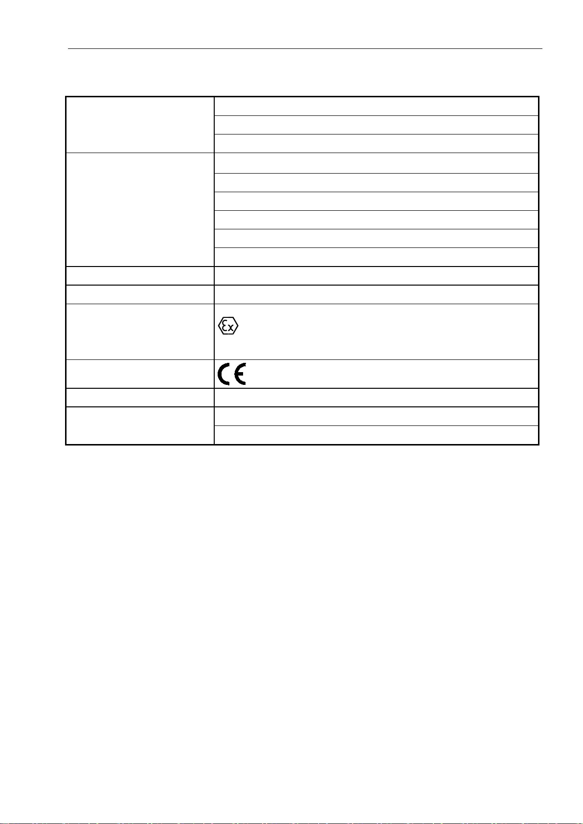
II 3G Ex ic nA IIC T4 Gc
Ex classification
II 3D Ex ic tc IIIB T50°C Dc IP54 or
II 3D Ex ic tc IIIC T50°C Dc IP65
CE marking
Type examination certificate TÜV 11 ATEX 7618 X
Service
Only by qualified service personnel authorized by SysTec GmbH
Addresses on request

12 Technical Manual IT1000-**-*-Ex2/22 Rev. 9
2 System Description
2.1 General
IT1000-Ex2/22 is a general purpose weighing terminal for use in a variety of applications such as data
logging, data capturing, parts counting, setpoint control and filling, suitable for installation in Ex zones
2 and 22.
The weighing module ADM is used to connect one scale base with strain gauge loadcells with an
overall impedance of 21 Ω to 4500 Ω. In addition a battery-backed realtime clock can be installed.
Power supply through the built-in wide-range power supply unit is either for 110–240 VAC or 12–
30 VDC or 10–24 VDC (battery-powered version). Housings are available for both, desk-top/wallmount and panel-mount installation. Cables of all external components are connected at screw
terminals.
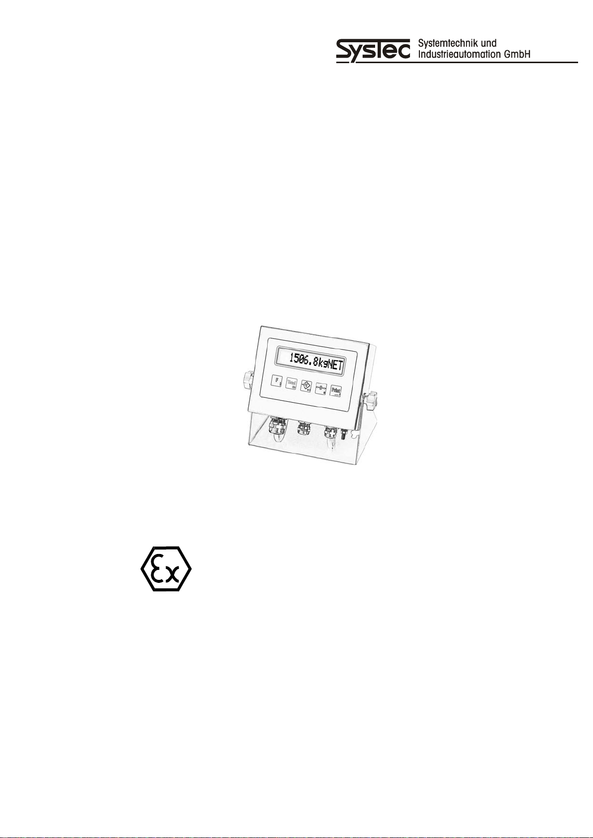
Weight and additional information is indicated on a back-lit 13-character LCD, height of characters
14mm. Operation is made via a sealed membrane keyboard with 5 keys.
Instead of operating the terminal locally via keyboard and display, full remote control is possible from a
PC. In applications legal for trade data can be stored in an approved data archive on the PC's harddisk.
This option requires the installation of the realtime clock in the weighing terminal and the PC program
PC COM+.

Technical Manual IT1000-**-*-Ex2/22 Rev. 9 13
2.2 Basic Units And Options
IT1000-Ex2/22 is available in 4 basic versions:
Type Housing Description Article-No.
IT1000-AC-W-Ex2/22 Wall-mount/
desk-top
Basic unit for wall-mount / desk-top installation
with 2.5 m line cord with free ends
to connect to 110–240 VAC
IT1000-AC-E-Ex2/22 Panel-mount Basic unit for panel-mount installation
with 2.5 m line cord with free ends
to connect to 110–240 VAC
IT1000-DC-W-Ex2/22 Wall-mount/
desk-top
Basic unit for wall-mount / desk-top installation
with screw terminals
to connect to 12–30 VDC
IT1000-DC-E-Ex2/22 Panel-mount Basic unit for panel-mount installation
with screw terminals
to connect to 12–30 VDC
IT1000-BATT-WEx2/22
Wall-mount/
desk-top
Basic unit for wall-mount / desk-top installation
with screw terminals
to connect to 12–30 VDC
IT1000-BATT-EEx2/22
Panel-mount Basic unit for panel-mount installation
with screw terminals
to connect to 12–30 VDC
The following modules are available as options:
Option
Description Article-No.
X1SYS001
X1SYS011
X1SYS005
X1SYS015
X1SYS006
X1SYS016
ADM Plug-on weighing module for connection of analog loadcells 13OPT100
SIM-RS232 Plug-on module with serial RS232 interface 10OPT220
SIM-20mA Plug-on module with serial 20mA interface 10OPT221
SIM-RS485.4 Plug-on module with serial RS485 4-wire interface 10OPT222
SIM-RS485.2 Plug-on module with serial RS485 2-wire interface 10OPT225
SIM-RS485.Opto Plug-on module with opto-isolated serial RS485 interface 10OPT230
DAU15 Plug-on module with analog 0/2–10 V or 0/4–20 mA output 10OPT231
PIM Plug-on module with two digital inputs/outputs 10OPT300
IOM Plug-on module with one digital input and 3 digital outputs 10OPT302
RTC DS1687-5 Plug-on module DS1687-5 with realtime clock, RAM and battery
13OPT500
backup
14 Technical Manual IT1000-**-*-Ex2/22 Rev. 9
Ex
2.3 Housing
IT1000-Ex2/22 is incorporated in a stainless steel housing with cable glands to connect cables to
peripheral devices. It is available in two versions:
The housing for desk-top / wall-mount installation (IT1000-**-W-Ex2/22) is protected to IP65.
The housing for panel-mount installation (IT1000-**-E-Ex2/22) is inserted in a suitable cutout of a
switch cabinet and fixed from the rear with 6 mounting brackets. When installed accordingly, the front
of the terminal -in combination with the circumferential gasket between terminal and switch cabinet- is
protected to IP65.
When installed in Ex zone 2 (as per II 3G Ex ic nA IIC T4 Gc) and Ex zone 22 with non-conductive dust
(as per II 3D Ex ic tc IIIB T50°C Dc IP54) the surrounding housing must be protected to IP54 or better.
When installed in Ex zone 22 with conductive dust (as per II 3D Ex ic tc IIIC T50°C Dc IP65) the
surrounding housing must be protected to IP65 or better.
The surrounding housing (e.g. switch cabinet) must conform to the requirements of EN60079-0 section
26.4.
See section 'Dimensions' for space requirements.
The housings must be included in the equipotential bonding of the installation.

Technical Manual IT1000-**-*-Ex2/22 Rev. 9 15
2.4 Description Of Components
2.4.1 Main Module CPU1000
The CPU1000 is the main module of the IT1000-Ex2/22 weighing terminal. It contains the
microcontroller, the power supply and the display. It also has a sockets to plug on the weighing module
ADM and a battery-backed realtime clock. An additional socket is provided that can be used
alternatively for a serial interface (SIM) or two digital I/Os (PIM) or an analog output (DAU15).
The following versions are available:
Main board Description Used for
CPU1000-230V-Ex2/22 CPU1000 with 110–240 VAC PSU IT1000-AC-*-Ex2/22
Article-No. X1SYS0x1
CPU1000-24VDC-Ex2/22 CPU1000 with 12–30 VDC PSU IT1000-DC-*-Ex2/22
Article-No. X1SYS0x5
CPU1000-NTA-Ex2/22 CPU1000 with 12–30 VDC PSU
and low-bat detection
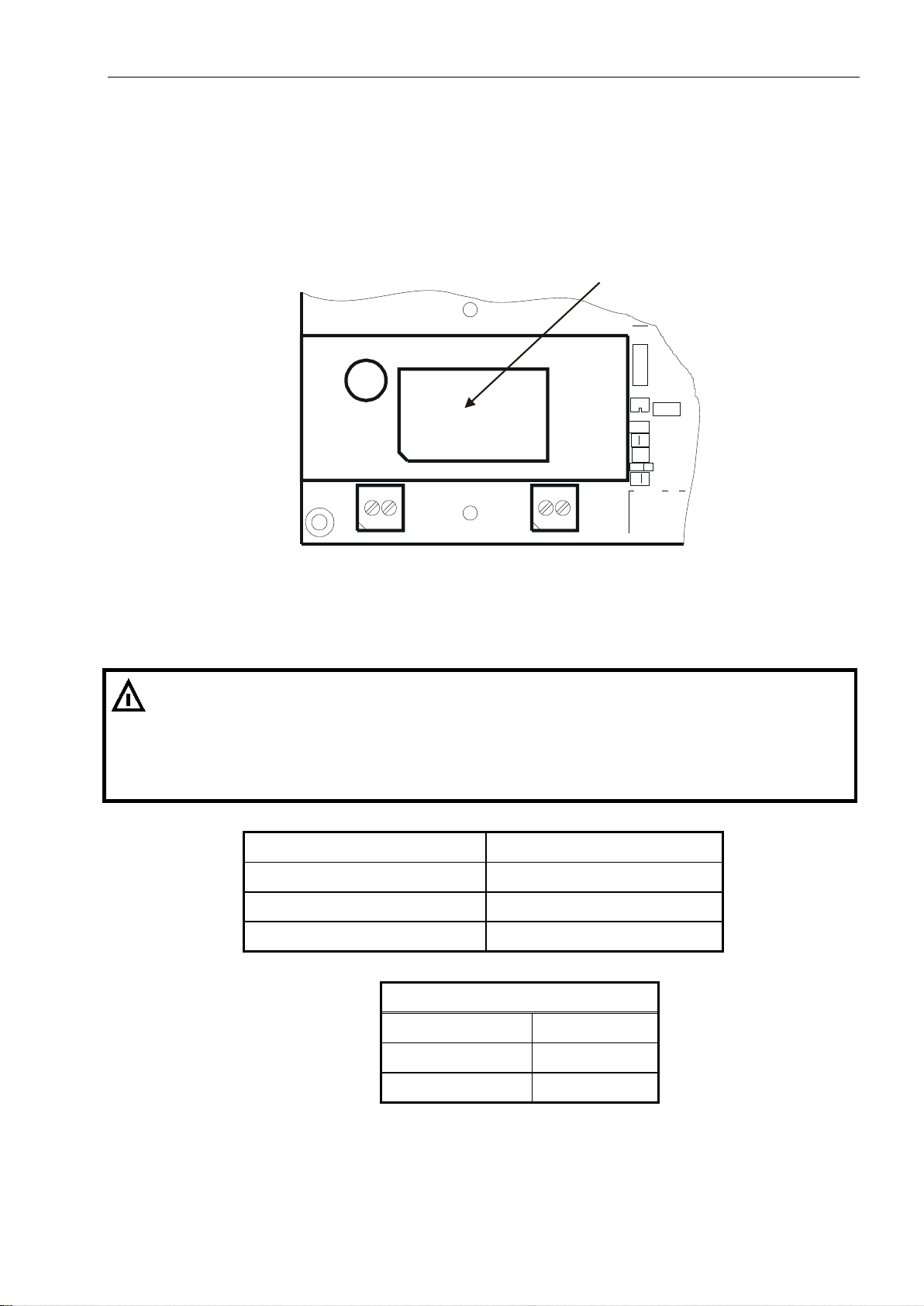
Layout of components on CPU1000 main module
Realtime clock Power supply
IT1000-DC-*-Ex2/22
Article-No. X1SYS0x6
X3 / X4
Socket for
ADM weighing
module
Terminal KL1 Terminal KL2 Terminal KL3 Keyboard
power supply PE I/O interface
16 Technical Manual IT1000-**-*-Ex2/22 Rev. 9
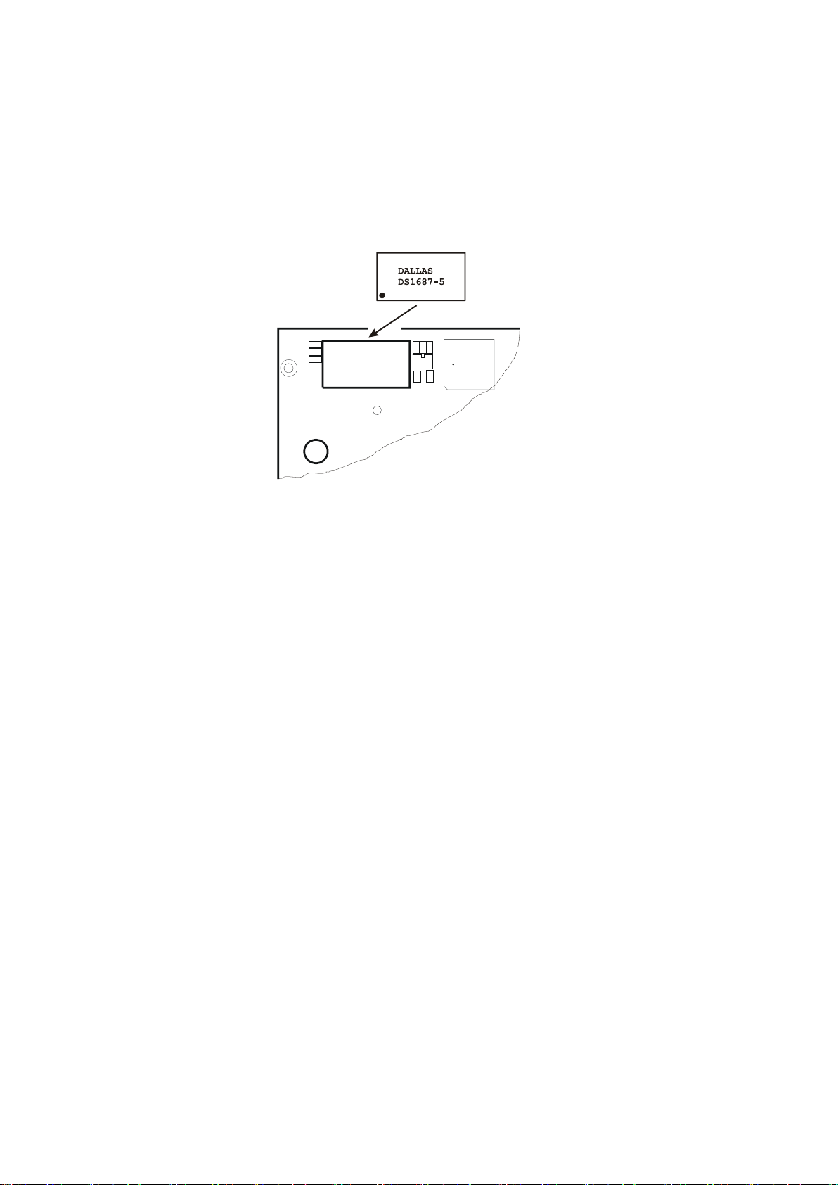
2.4.2 Battery-Backed Realtime Clock RTC DS1687-5
As an option a module with realtime clock and 240 bytes of battery backed memory (e.g. for totals)
can be installed. The integrated lithium battery has a lifetime of approx. 10 years.
The realtime clock is required for applications using the external data archive on PC harddisk because
the ident-No. (which in conjunction with the date serves to identify a record in the archive) is stored in
the memory of the module.
Insert with mark pointing to the left
Notes:
• For the storage of volatile data the module of the optional realtime clock contains a lithium battery.
Dispose of used batteries as indicated by manufacturer.
• If no realtime clock is installed, entry of date and time is required on power up!
• For replacing the module observe the instructions in section 'Replacing the battery'!
Technical Manual IT1000-**-*-Ex2/22 Rev. 9 17
Ex
Ex2/22 is also an apparatus of group II category 3D, that following RL 99/92/EG (ATEX
Ex2/22 must have
Ex
of the intended use is observance of this Technical Manual and the adherence to inspection and
3 Intended Use
In compliance with RL 2014/34/EU appendix I, the weighing terminal IT1000-Ex2/22 is an
apparatus of group II category 3G, that following RL 99/92/EG (ATEX 137), can be used in
zone 2, as well as in gas groups IIA, IIB and IIC, which are at risk of explosion through
combustible substances of temperature classes T1 to T4. The following section 'Installation of
'IT1000-**-E-Ex2/22 in switch cabinet' must be observed.
IT1000-
137) can be used in zone 22 (dust), the maximum surface temperature is 50°C. The following
instructions on the installation of the IT1000-**-E-Ex2/22 in a surrounding housing must be
observed.
Installation of 'IT1000-**-E-Ex2/22 in switch cabinet: The housing for panel-mount installation
is inserted in a suitable cutout of a switch cabinet and fixed from the rear with 6 mounting
brackets. If installed accordingly, the front of the terminal -in combination with the
circumferential gasket between terminal and switch cabinet- is protected to IP65. When
installed in Ex zone 2 (as per II 3G Ex ic nA IIC T4 Gc) and Ex zone 22 with non-conductive
dust (as per II 3D Ex ic tc IIIB T50°C Dc IP54) the surrounding housing must be protected to
IP54 or better. When installed in Ex zone 22 with conductive dust (as per II 3D Ex ic tc IIIC
T50°C Dc IP65) the surrounding housing must be protected to IP65 or better. The surrounding
housing (e.g. switch cabinet) must conform to the requirements of EN60079-0 section 26.4.
The weighing terminal must not be installed in areas where electrostatic charging is possible
which may produce spark discharges, brush discharges or propagating brush discharges at the
front panel.
All external connections are designed for type of protection Ex 'nA'. The connection values
shown in chapter 'Installation of external connections with type of protection Ex-nA' must be
observed.
When installed in hazardous area, all peripheral devices connected to IT1000appropriate Ex protection.
The metal housing of the IT1000-Ex2/22 terminal must be integrated at the PA stud into the
equipotential bonding system of the installation. Use suitable serrated washers.
The permissible range of ambient temperature is –10 °C to +40 °C.
When installing IT1000-**-E-Ex2/22 in a switch cabinet (panel-mount version), this
temperature range also applies to the inside the switch cabinet.
Furthermore, for use and installation all requirements as per EN 60079-14 must be observed.
Any other but the intended use of the equipment, modifications and extensions must not be
made without the explicit approval of the manufacturer and is deemed not to be intended. Part
maintenance instructions and intervals. The manufacturer does not assume any liability
whatsoever for damages resulting from non-intended use. Any risk resulting from non-intended
use is solely borne by the user.
The weighing terminal and all connected components must be integrated into a common
system of equipotential bonding.
Protective covers or other parts covering the housing completely or in part must not be used.
The housing must be protected against permanent exposure to ultraviolet radiation.

18 Technical Manual IT1000-**-*-Ex2/22 Rev. 9
Ex
4 Assembly
It must be made sure that installation of the weighing terminal is only carried out when all
power to the instrument is disconnected and no potentially explosive atmosphere is present.
The weighing terminal must not be installed in areas where electrostatic charging is possible
which may produce spark discharges, brush discharges or propagating brush discharges at the
front panel.
Installation must be made in compliance with the generally accepted rules of technology. In particular
for all work carried out on electrical installations the specific safety regulations must be observed.
The weighing terminal may be installed in Ex zone 2 or 22. The terminal must not be damaged. The
place of installation must be clean.
The IT1000-**-W-Ex2/22 (wall-mount / desk-top version) has mounting brackets for wall or table-top
installation. They must be fixed with suitable screws which are not part of the supply. All screws must
be tightened securely.
The IT1000-**-E-Ex2/22 (panel-mount version) has screw clamps to fix the terminal in the cutout of
the switch cabinet. To connect the bonding conductor, an M5 stud is provided at the rear or bottom of
the housing. Use serrated washers to prevent the nuts from becoming loose.
The permissible temperature range is –10 °C to +40 °C at a max. of 95% relative humidity (non
condensing). Direct exposure to ultraviolet radiation must be avoided.
For wall-mount installation the unit can be fixed at the wall first and then the cables can be installed
with the front lid open.
Before the device is put into operation, the housing must be closed and tightened securely with the
hexagonal nuts provided. The nuts must be tightened with a torque of 1.1 Nm.
Technical Manual IT1000-**-*-Ex2/22 Rev. 9 19
Ex
This apparatus must only be installed by qualified personnel who are familiar with all regulations
Ex
Ex
Ex
5 Installation
5.1 General
applicable to the different types of protection and the methods of installation, as well as the
general principles for the classification of zones. This level of competence must correspond to
the work that is to be carried out and appropriate training should be provided on a regular basis.
When the weighing terminal is to be installed in Ex zone 2 / 22 the regulations as per
EN 60079-14 must be adhered to.
The weighing terminal must not be installed in areas where electrostatic charging is possible
which may produce spark discharges, brush discharges or propagating brush discharges at the
front panel.
It must be made sure during installation of the weighing terminal that all power to the
instrument is disconnected and that no potentially explosive atmosphere can be present at any
time.
Installation must be carried out in compliance with applicable DIN/VDE regulations. Also, all
country-specific regulations must be observed. Connection of supply voltage must be made in
compliance with VDE 0100 and VDE 0160.
When the instrument is permanently connected to the power supply, an easily accessible
separator must be included in the supply circuit! It must either be located in safe area or -if
installed in Ex area- have appropriate Ex protection for the place of installation.
All cables are led into the housing through Ex cable glands. Strip cable jacket only as long as
required for the wires to reach the screw terminals. Use wire end ferrules with plastic collar on
stranded cable and avoid protruding wires. When assembling the cable glands make sure that
shield of cable is connected inside the cable gland. Observe instructions in section 'Connection
of cables'.
Before the device is put into operation, make sure that the housing is closed and tightened
securely with all hexagonal nuts provided (torque: 1.1 Nm).
5.2 Equipotential Bonding
In compliance with EN 60079-14 the apparatus must be integrated into the equipotential
bonding system of the installation. The bonding conductor must have a cross section of min.
4 mm². To connect the bonding conductor, an M5 stud with serrated washer is provided at the
rear or bottom of the housing.
5.3 Shielding
Use only shielded connection cables. The shield must be connected at both sides in the cable
glands. It is mandatory to additionally install equipotential bonding as per EN60079-14
paragraph 'additional requirements for the type of protection i-intrinsic safety' / section
'grounding of conductive shields' / exception b). The bonding conductor must have a cross
section of min. 4 mm².
20 Technical Manual IT1000-**-*-Ex2/22 Rev. 9
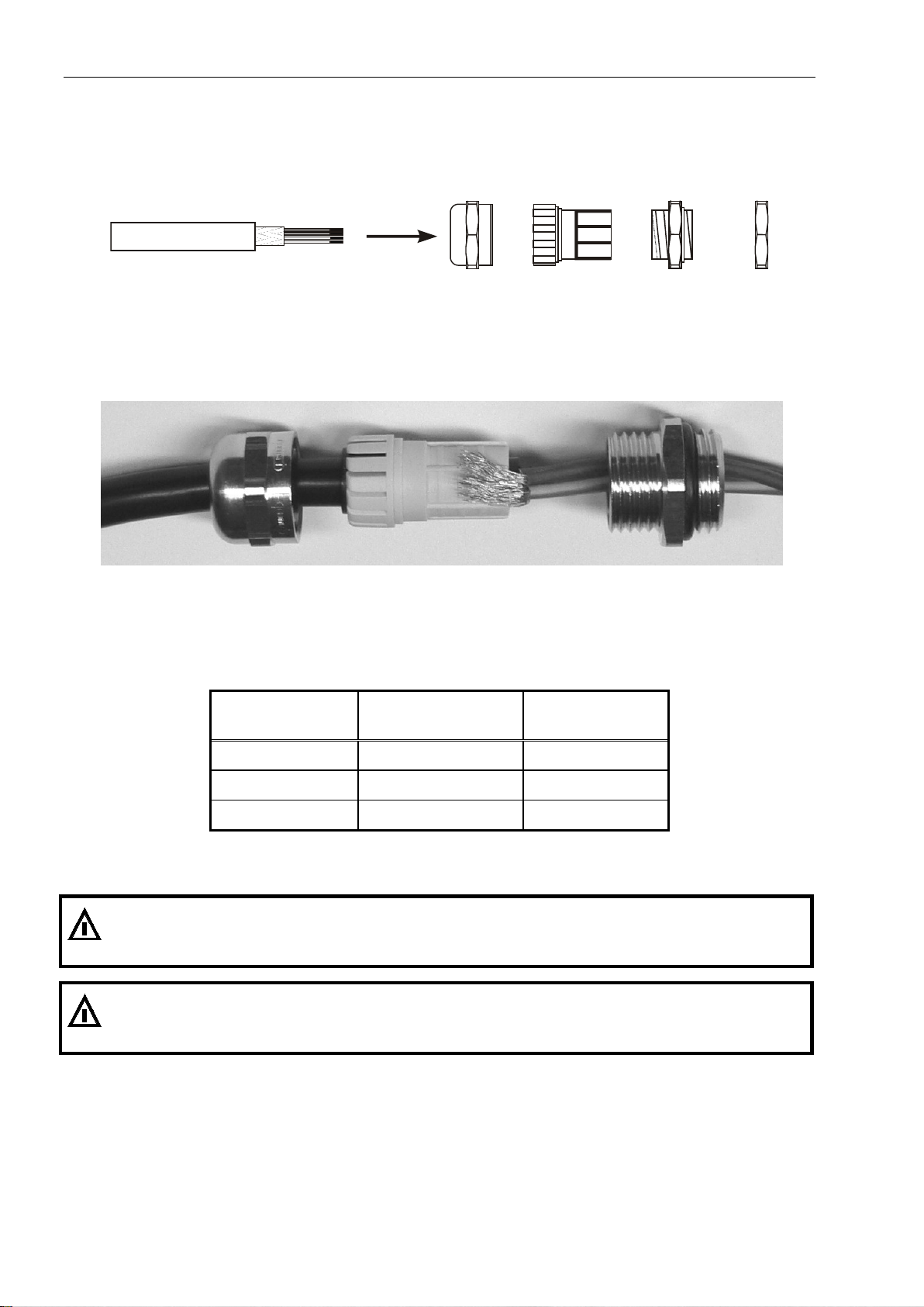
Cable jacket
Shield
Compression nut
Plastic insert
Bushing
Counter nut
Ex
Ex
5.4 Connection Of Cables
All cables are led into the housing through Ex cable glands.
1. Slide compression nut over cable jacket;
2. Slide plastic insert (retainer) over cable jacket until inner end is aligned with cut end of jacket;
3. Unravel shield, bend over retainer and push into retaining comb to ensure good conductive contact
with housing. Cut wires of shield to length of comb, avoid protruding wires that would endanger
tightness of cable gland;
4. Insert retainer with cable into bushing;
5. Screw compression nut onto bushing and use wrench to tighten securely.
Permissible diameter of cables and torque for cable glands:
Wrench size of
counter nut
Permissible diameter
of cable
Torque to tighten
counter nut
17 mm 4–8 mm 6 Nm
20 mm 5–10 mm 5 Nm
22 mm 6–12 mm 8 Nm
Contact SysTec service for different cable diameters.
Use crimped wire end ferrules with plastic collar on stranded cable and avoid protruding wires.
All connecting cables must be firmly installed to avoid tension load at the cable glands and to
comply with the requirements of EN60079-14 paragraph 'cables and lines for permanent
installation'.
Technical Manual IT1000-**-*-Ex2/22 Rev. 9 21
Ex
6 Installation Of External Connections With Type Of
Protection 'Ex-nA'
6.1 Connection Of Power Supply To IT1000-AC-*-Ex2/22
IT1000-AC-*-Ex2/22 (article-No. X1SYS0x1) is supplied with a line cord with free ends for the supply
voltage.
Power supply unit
L1 N PE
Terminal KL1 Terminal KL2
110 V (–15%) to 240 V (+10%),
50/60Hz
The connection of the supply voltage at the free cable end of the weighing terminal IT1000-AC*-Ex2/22 is designed for type of protection Ex-nA. The listed nominal connection values must
be adhered to.
For the connection of the line cord in hazardous area a suitable method must be chosen in
compliance with EN60079-0 (e.g. Ex-e, Ex-d). A suitable protection against overload and short
circuit in compliance with VDE regulations must be provided.
Nominal voltage U
Nominal current IN
N 110–240 VAC –15 %/+10 %
100 mA
Frequency range 47–63 Hz
Type of protection
Ex-nA
Color code free end of cable
brown L
blue N
green/yellow PE
22 Technical Manual IT1000-**-*-Ex2/22 Rev. 9
Ex
6.2 Connection Of Power Supply To IT1000-DC-*-Ex2/22 And IT1000-BATT-*-Ex2/22
The supply voltage for the weighing terminal IT1000-DC-*-Ex2/22 is connected at screw terminal KL1
of the CPU1000-24VDC-Ex2/22 (article-No. X1SYS0x5).
The supply voltage for the weighing terminal IT1000-BATT-*-Ex2/22 is connected at screw terminal
KL1 of the CPU1000-NTA-Ex2/22 (article-No. X1SYS0x6).
DC/DC converter
+V 0 V PE
Terminal KL1 Terminal KL2
12–30 VDC
The connection of the supply voltage to the weighing terminal IT1000-DC-*-Ex2/22 is designed
for type of protection Ex-nA. The listed nominal connection values must be adhered to.
For the connection of the supply cable in hazardous area a suitable method must be chosen in
compliance with EN60079-0 (e.g. Ex-e, Ex-d). A suitable protection against overload and short
circuit in compliance with VDE regulations must be provided.
Nominal voltage U
N: 12–30 VDC +10 % / –15 %
Nominal current IN: 330–100 mA
Cross section (rigid wires): 0.75–1.5 mm2
Cross section (flexible wires with insolated wire end ferrule): 0.75–1.5 mm2
Length of stripped insolation: 6 mm
Fastening torque screw terminal: 0.5–0.6 Nm
Ex type of protection: Ex-nA
Terminal assignment KL1
+ V Supply voltage (+)
0 V Supply voltage (—)
Technical Manual IT1000-**-*-Ex2/22 Rev. 9 23
6.3 Operation Of IT1000-BATT-*-Ex2/22
During the power up sequence the current charge state of the battery pack is briefly displayed,
followed by program version, date and time. If the indicator is not fitted with a realtime clock module,
data and time must be entered anew everytime the unit is switched on. The charge state can also be
viewed during running operation. To call up this function briefly press F / Up key three times.
The indicator is switched on by pressing the Print / Enter key once, to switch it off press F / Up key for
approx. 3 sec.
Battery life of a new, fully charged battery pack is max. 40 hours, depending on the connected
loadcells and the use of the backlighting. Charge time of a discharged battery pack is approx. 3 hours.
Battery life also depends on several other factors such as ambient temperature, number of charge
cycles and hardware configuration of the IT1000 terminal.
Note: When the IT1000-BATT terminal is supplied from an external battery, under '\ Service Menu \
General \ Batt' the respective type must be chosen, this choice affects the automatic power off
switching when battery is low:
Battery symbol lights
up at approx.
24Pb 24 V lead battery 23 V 22 V
Switching off
at approx.
12Pb 12 V lead battery 11.5 V 11 V
Line mains operation 10 V 9 V
When battery is low, this is indicated with a flashing symbol at the right hand side of the display. The
operator should then recharge the battery.
The charging of the rechargeable battery is indicated by a flashing triangle (version 2.29 or higher).
To avoid deep discharge of the battery, the IT1000-BATT is automatically switched off when the
voltage falls below the min. value. Before this happens, the message 'Low Battery' is shown for
approx. 2 min. If the unit is switched on again, 'Low Battery' is shown for approx. 2 minutes and then
the terminal is automatically switched off again to avoid deep discharge damage to the battery.
24 Technical Manual IT1000-**-*-Ex2/22 Rev. 9
Ex
6.3.1 Connecting Cable With Ex Plug For Battery Operation
The weighing terminal IT1000-BATT-*-Ex2/22 (article-No. X1SYS0x6) with CPU1000-NTA-Ex2/22 is
suitable for connection to an external rechargeable battery box. To this effect the instrument can be
supplied with an assembled connecting cable (E3KAB003) with ex plug. This cable must be ordered
separately.
The following notes must absolutely be observed:
Absolutely adhere to the operating instructions 'DXN' provided by Marechal
Components must have identical coding, or damages to connector / socket cannot be ruled
out.
The connector cable must be firmly installed in a suitable way to protect it against
mechanical damage. An appropriate type of cable must be chosen that complies with the
thermal and mechanical requirements at the place of installation.
If connectors are not connected correctly, protection against risk of explosion is no longer
ensured. Strictly follow the instructions!
Immediately after disconnecting, cover voltage-conducting components with protective cap!
The following rechargeable batteries can be used for the supply of the weighing terminal:
1) AkkuBox Ex; 12 VDC for use in Ex zone 2 and 22
Article-No. E3AKK002 / E3AKK003
2) The use of alternative 12 V batteries is possible. However, when used in hazardous
area they must have appropriate ex protection. The requirements of EN 60079-14 must
be observed.
The operating instructions of the rechargeable battery must be observed.
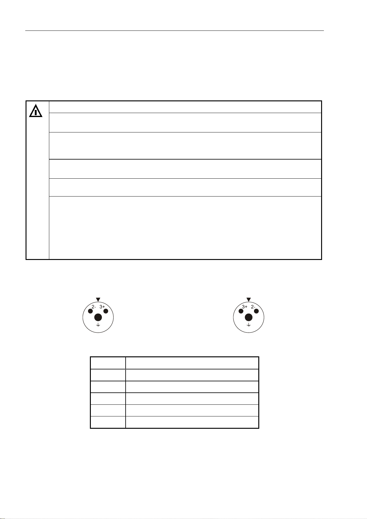
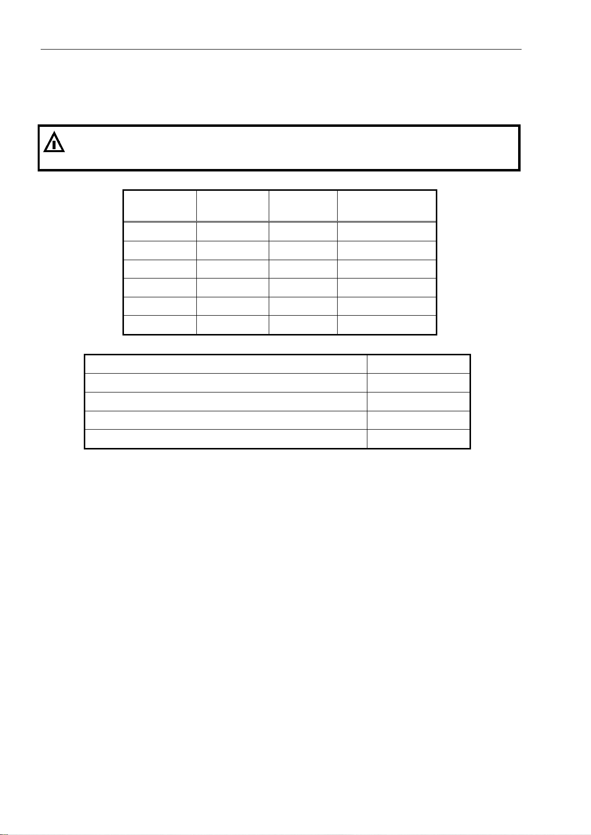
6.3.2 Assignment DXN1 Connector
Top view socket Top view connector
DXN1 Pin Assignment
1
2–
3+
PE
N
not used
GND
+12 VDC
Shield
not used
Technical Manual IT1000-**-*-Ex2/22 Rev. 9 25
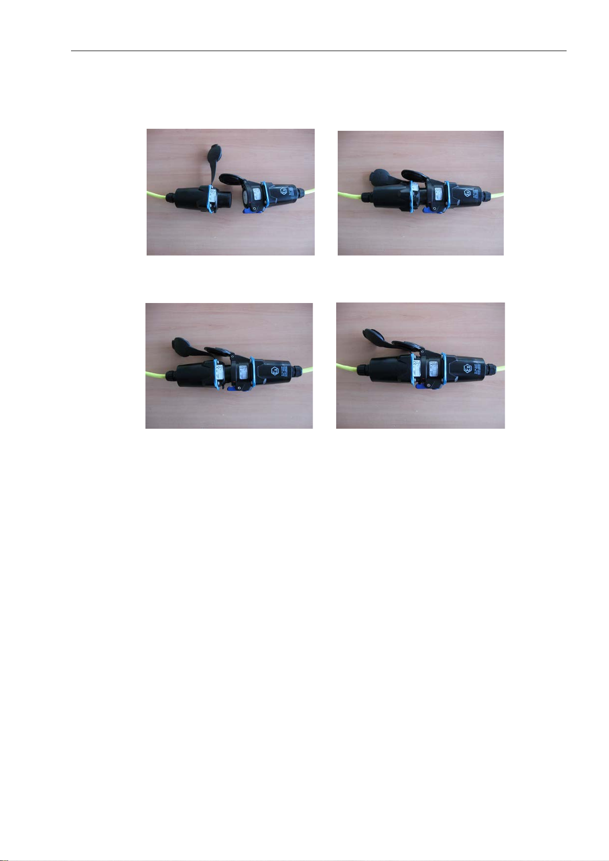
6.3.3 Instructions For Connecting And Separating Connectors
1. Open protective caps before plugging and check connector/socket for damages.
2. Align male/female connectors along red arrows and insert into groove.
1)
2)
3. Turn connector/socket right by approx. 45° to stop.
4. Plug in connector/socket until they click into place and are held by the blue hook.
3)
4)
Disconnect in reverse order.
26 Technical Manual IT1000-**-*-Ex2/22 Rev. 9
Ex
6.4 Connection Of Analog Scale To ADM
The Analog Digital Module ADM is plugged into the socket ADM on the CPU1000. It provides
connection for one analog scale base.
The connection is designed compliant to type of protection 'Ex-nA'. If the loadcell is to be
installed in hazardous area, compliance with the applicable Ex regulations is mandatory. The
following connection values must be observed:
ADM
Signal Description Nominal value
Terminal KL1
1 +Excitation Output 5 V / 240 mA
2 – Excitation Output 5 V / 240 mA
3 +Sense Input 5 V / 1 mA
4 – Sense Input 5 V / 1 mA
5 +Signal Input 5 V / 1 mA
6 – Signal Input 5 V / 1 mA
Cross section rigid wire: 0.25–1.5 mm
2
Cross section flexible wire with insolated wire end ferrule: 0.25–1.5 mm2
Length of stripped insolation: 6 mm
Fastening torque screw terminal: 0.5–0.6 Nm
Ex type of protection: Ex-nA
Connection of weighing platforms and loadcells is to be made as specified below:
• Max. 16 strain gauge loadcells 350 Ω each
• Overall impedance 21.5 Ω ...4500 Ω
• W&M approved resolution of 6,000 e at a max. preload of 80%, internal resolution 524,000 d
• Smallest permissible input signal for approved applications: 0.33 µV / e
• Update rate 50 updates / second
• Loadcell excitation: 5 V ±5 %, gated power supply
• Connection in 4- or 6-wire mode.
Technical Manual IT1000-**-*-Ex2/22 Rev. 9 27
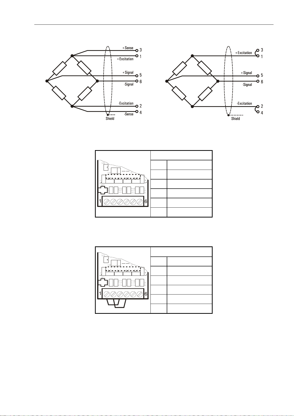
Principal schematics of 6-wire and 4-wire strain gauge loadcell
6-wire loadcell
4-wire loadcell
Connection of 6-wire analog loadcell(s) to the ADM module:
Terminal Assignment
1 +Excitation
2 – Excitation
3 +Sense
4 – Sense
5 +Signal
6 – Signal
Connection of 4-wire analog loadcell(s) to the ADM module:
To connect loadcells without sense lines (4-wire connection), two jump leads must be connected at
terminal strip KL1 between terminal 1 and 3, and between terminal 2 and 4.
Terminal Assignment
1 +Excitation
2 – Excitation
3
4
5 +Signal
6 – Signal
28 Technical Manual IT1000-**-*-Ex2/22 Rev. 9
6.4.1 Connection Cables For Analog Weighing Platforms
For the installation of connection cables for analog weighing platforms please follow the
recommendations listed below:
• Only use suitable loadcell cable,
(e.g. SysTec cable 10KAB214, 3 x 2 x 0.75 mm², shielded)
Nominal Voltage of cable ≥250 V.
Unsuitable loadcell cable may affect accuracy.
• The shield of the loadcell cable must be connected all around the cable in the cable gland of the
weighing terminal (see also chapter 'Installation' / 'Connection Of Cables'). If an extension of the
loadcell cable is required use only metal junction boxes and cable glands. The shield on both sides
must be connected in the same way as at the terminal. Loadcells and/or weighing platforms,
junction boxes and the terminal must be included in the potential equalization of the components of
a weighing system. Depending on the situation on site this may require the installation of a separate
earth lead of appropriate diameter (e.g. 16 mm²) in parallel to the loadcell cable.
• Distance between loadcell cables and power lines: ≥0.5 m. Loadcell cables to be installed in
grounded metal conduits, metal hoses or metal cable trays.
• Maximum length of connection cable between scale base and weighing terminal: 200 m.
• If tension load is applied to loadcells instead of compression load, connection for +Signal and
–Signal must be transposed.
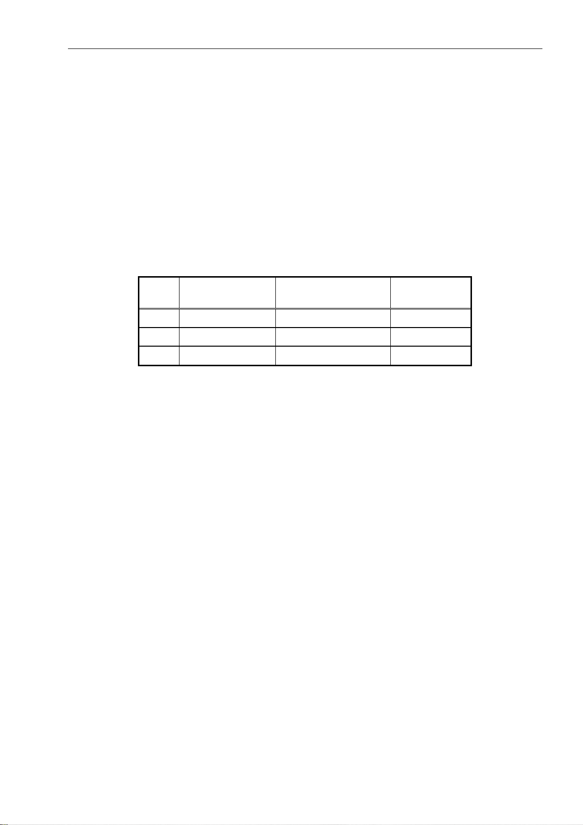
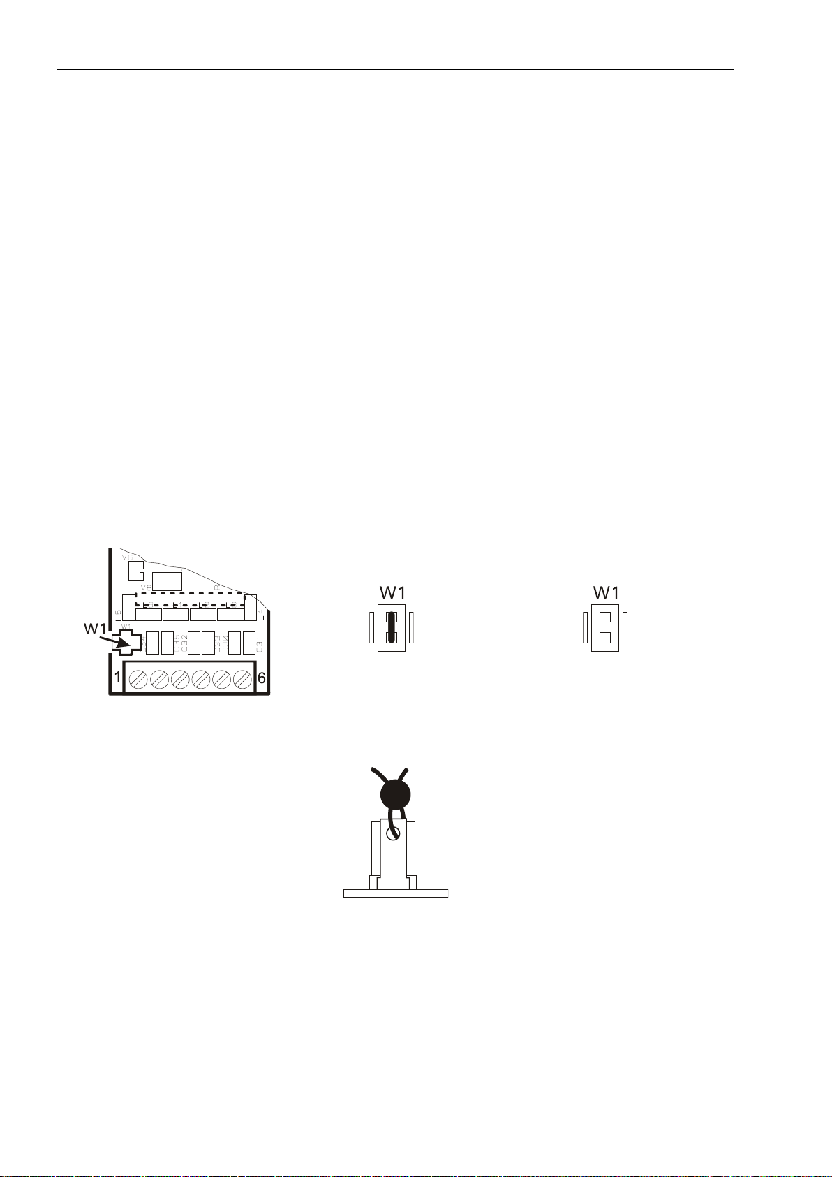
6.4.2 Securing Scale Parameters
The scale parameters are stored in EEPROM and secured with the jumper W1:
Calibration data secured
W&M approved applications require that the calibration parameters be protected against unauthorized
modifications. To that effect the jumper can be sealed with thread and lead seal or adhesive label.
For a description of the scale calibration refer to the respective chapter.
Calibration and storing released
Technical Manual IT1000-**-*-Ex2/22 Rev. 9 29
Ex
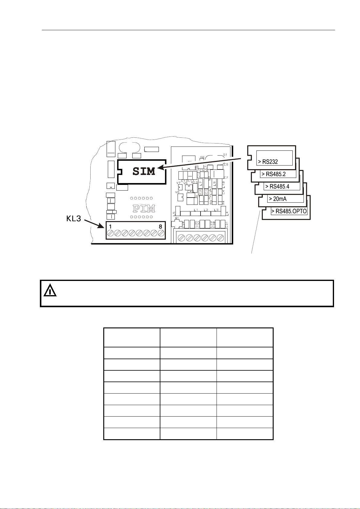
6.5 Connection Of Serial Interface SIM
In the SIM socket one of the following interface modules (SIM) can be inserted:
• SIM-RS232
• SIM-RS485 2-wire
• SIM-RS485 4-wire
• SIM-RS485.OPTO 2/4-wire opto isolated
• SIM-20mA CL (passive).
Note: If an interface module is installed in the SIM socket, the PIM socket must remain free!
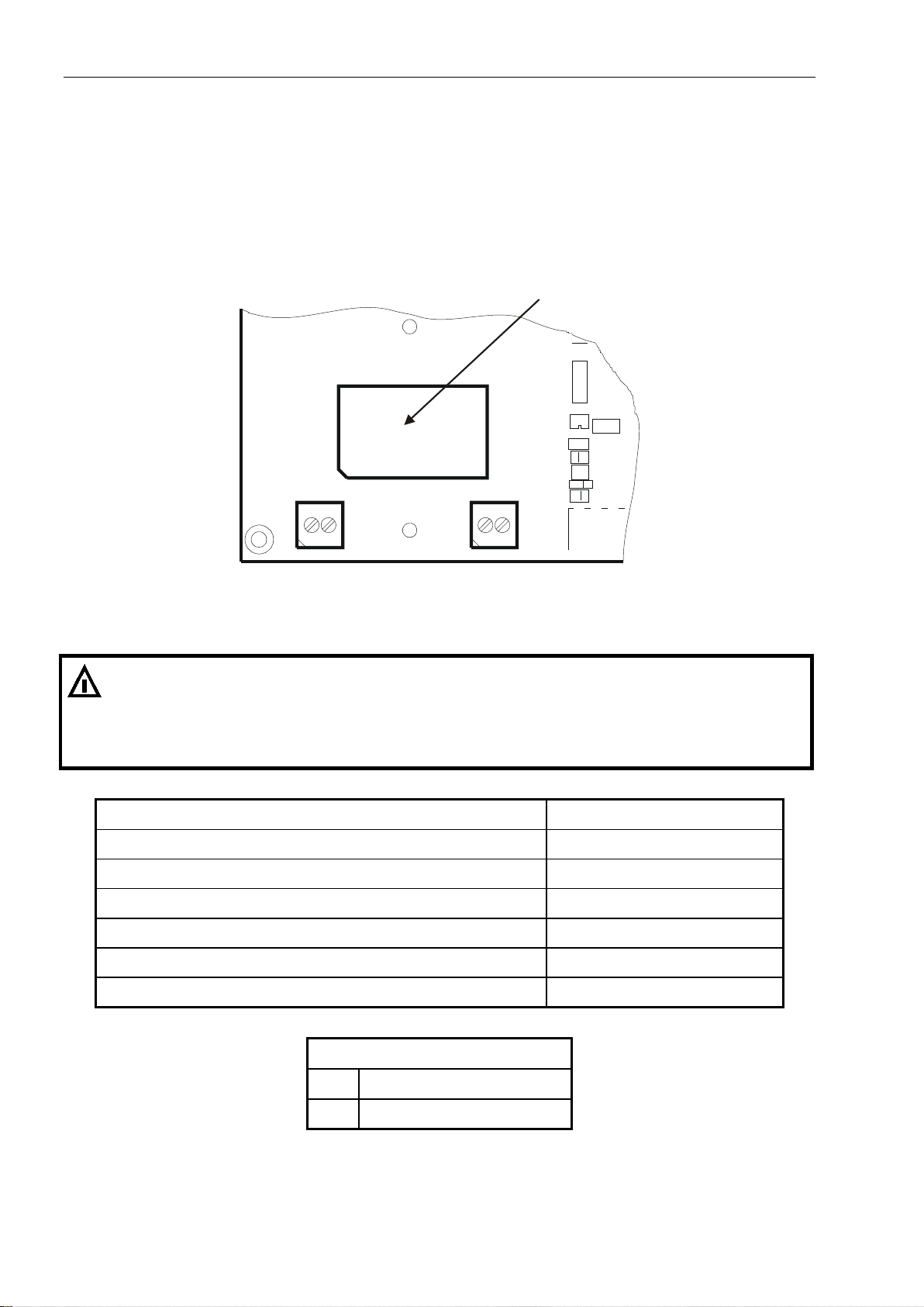
Position of serial interface on CPU1000 board
Insert with notch
pointing to the left!
Peripheral devices are connected at CPU1000 screw terminal KL3. The connection is designed
compliant to type of protection 'Ex-nA'. The following connection values must be observed:
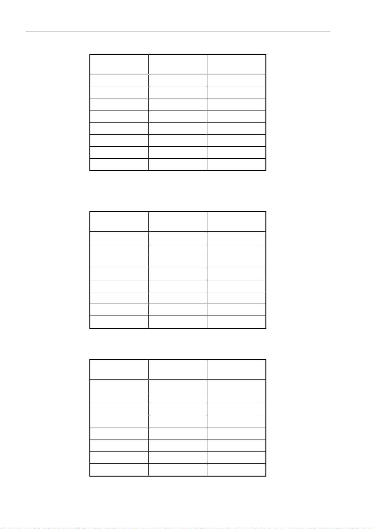
SIM-RS232:
CPU1000
Description Nominal value
Terminal KL3
1 GND ±12 VDC
2 — not used
3 — not used
4 — not used
5 TxD ±12 VDC
6 RTS ±12 VDC
7 RxD ±12 VDC
8 CTS ±12 VDC
30 Technical Manual IT1000-**-*-Ex2/22 Rev. 9
SIM-RS485-2-wire:
SIM-RS485-4-wire:
SIM-RS485-OPTO:
CPU1000
Description Nominal value
Terminal KL3
1 — not used
2 — not used
3 — not used
4 — not used
5 A (TxD+/ RxD+) 5 VDC
6 B (TxD– / RxD–) 5 VDC
7 A (TxD+/ RxD+) 5 VDC
8 B (TxD– / RxD–) 5 VDC
CPU1000
Description Nominal value
Terminal KL3
1 — not used
SIM-20mA:
2 — not used
3 — not used
4 — not used
6 TxD+ 5 VDC
7 TxD– 5 VDC
8 RxD+ 5 VDC
9 RxD– 5 VDC
CPU1000
Description Nominal value
Terminal KL3
1 — not used
2 — not used
3 — not used
4 — not used
6 TXIN 12 VDC / 20 mA
7 TXOUT 12 VDC / 20 mA
8 RXIN 12 VDC / 20 mA
9 RXOUT 12 VDC / 20 mA
 Loading...