

Page 1

SysOnChip
LOOK’ET LBS User Manual
SOC LBS LOOK’ET User Manual
2007. 10. 11.
Sysonchip, Inc.
1
Page 2

SysOnChip
SOC LBS LOOK’ET User Manual
Contents
1. Overview....................................................................................................................................................................6
1.1. Reference..................................................................................................................................................6
1.2. Hardware overview................................................................................................................................7
1.3. Hardware interface description..........................................................................................................9
1.3.1. Vehicle interface.........................................................................................................................9
1.3.1.1. Vehicle 12 pin interface pin out...............................................................................................9
1.3.1.2. Vehicle 12 pin interface pin & cable description......................................................................9
1.3.2. USB interface............................................................................................................................10
1.3.3. RS232 interface........................................................................................................................10
1.3.4. External GPS antenna............................................................................................................10
1.3.5. External GSM/GPRS antenna.............................................................................................10
1.3.6. LEDs............................................................................................................................................. 11
1.4 LOOK’ET basic operation scheme...................................................................................................12
2. Security....................................................................................................................................................................13
3. Safety standards......................................................................................................................................................13
4. Basic startup and testing..........................................................................................................................................14
4.1. Needed accessory and programs...................................................................................................14
4.1.1. Hardware accessories............................................................................................................15
4.1.2. Software programs..................................................................................................................18
4.2. Testing environment & Installation ..................................................................................................19
4.2.1. Testing environment................................................................................................................19
4.2.2. Installation & Usage.................................................................................................................20
4.2.2.1. Component connection.........................................................................................................20
4.2.2.2. USB driver installation & test................................................................................................22
4.2.2.3. DM installation......................................................................................................................22
4.2.2.4. Configuration setting by DM..................................................................................................22
4.2.2.5. Confirm the connection with control center...........................................................................22
4.2.2.6. Program updating.................................................................................................................22
5. Specification.............................................................................................................................................................23
5.1. Software features..................................................................................................................................23
5.2. Hardware features................................................................................................................................23
5.3. Technical specification
6. History......................................................................................................................................................................26
........................................................................................................................24
2
Page 3

SysOnChip
Table 1. Vehicle interface pin description table...........................................................................................10
Table 2. LED indications............................................................................................................................. 11
Table 3. GSM/GPRS module specification.................................................................................................24
Table 4. GPS module specification.............................................................................................................25
SOC LBS LOOK’ET User Manual
Table Contents
3
Page 4

SysOnChip
Fig 1. LOOK’ET hardware block diagram.....................................................................................................7
Fig 2. LOOK’ET appearance in front view....................................................................................................7
Fig 3. LOOK’ET appearance in right side view.............................................................................................8
Fig 4. LOOK’ET appearance in left side view...............................................................................................8
Fig 5. . LOOK’ET appearance including tray................................................................................................8
Fig 6. Vehicle 12 pin connector cable part....................................................................................................9
Fig 7. Vehicle 12 pin connector LOOK’ET part.............................................................................................9
Fig 8. Hardware/Software accessories.......................................................................................................14
Fig 9. Hardware Accessory : Body.............................................................................................................15
Fig 10. Hardware Accessory : External GPS antenna................................................................................15
Fig 11. Hardwa re Accessory : External GSM/GPRS antenna....................................................................15
SOC LBS LOOK’ET User Manual
Figure Contents
Fig 12. Hardware Accessory : vehicle 12 pin connector & cable................................................................16
Fig 13. Hardware Accessory : Internal battery............................................................................................16
Fig 14. Hardware Accessory : USB mini-type connector & cable...............................................................16
Fig 15. Hardware Accessory : LOOK’ET tray(Cradle)................................................................................17
Fig 16. Operation environment...................................................................................................................19
4
Page 5

SysOnChip
SOC LBS LOOK’ET User Manual
Cautions
Information provided by SYSONCHIP is accurate and reliable. However, no responsibility
is assumed for its use.
Please, read carefully the safety precautions.
If you have any technical questions regarding this document or the product described in it,
please contact your vendor or SYSONCHIP.
Trademarks
Some mentioned products are registered trademarks of their respective companies.
Copyright
This documentation is copyrighted by SYSONCHIP with all rights reserved.
No part of this documentation may be produced in any form without the prior written
permission of
SYSONCHIP.
5
Page 6

SysOnChip
SOC LBS LOOK’ET User Manual
1. Overview
This manual describes the SOC LBS Real-time GPS tracker for using in the fleet management and other location
utility.
We calls the SOC LBS Real-time GPS tracker as “LOOK’ET”, our product name in this document from now on.
Chapter 1 describes the LOOK’ET hardware part and 2,3 describe security and safety.
Chapter 4 describes the stating and testing method.
Chapter 5 describes the specification of LOOK’ET.
1.1. Reference
[1] SOC LBS USB Driver Installation Guide
[2] PC Application software Manual [ Control Center]
[3] PC Application software Manual [ Diagnostic Monitor]
[4] PC Application software Manual [ Upgrade Server]
[5] SOC LBS SW Interface
6
Page 7
SysOnChip
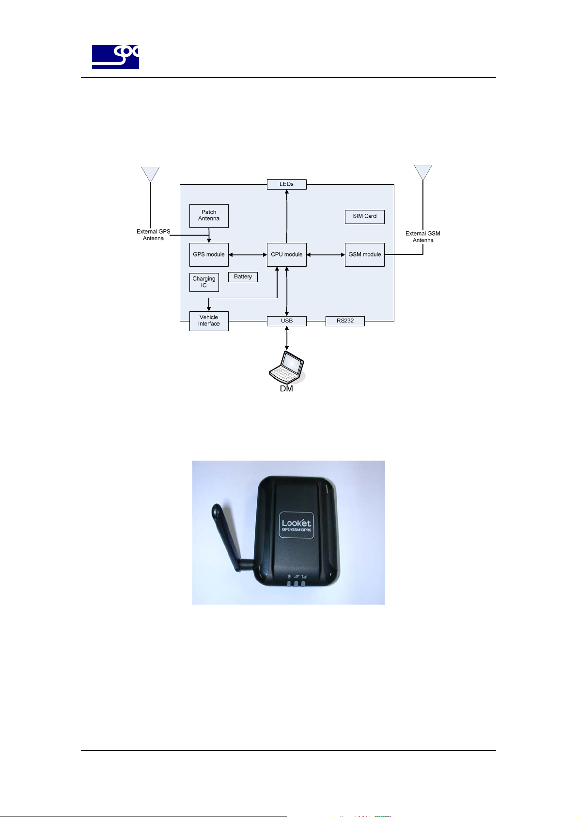
1.2. Hardware overview
LOOK’ET has following hardware block diagram.
SOC LBS LOOK’ET User Manual
Fig 1. LOOK’ET hardware block diagram
LOOK’ET has following hardware appearance.
Fig 2. LOOK’ET appearance in front view
7
Page 8

SysOnChip
Fig 3. LOOK’ET appearance in right side view
SOC LBS LOOK’ET User Manual
Fig 4. LOOK’ET appearance in left side view
Fig 5. . LOOK’ET appearance including tray
8
Page 9
SysOnChip
1.3. Hardware interface description
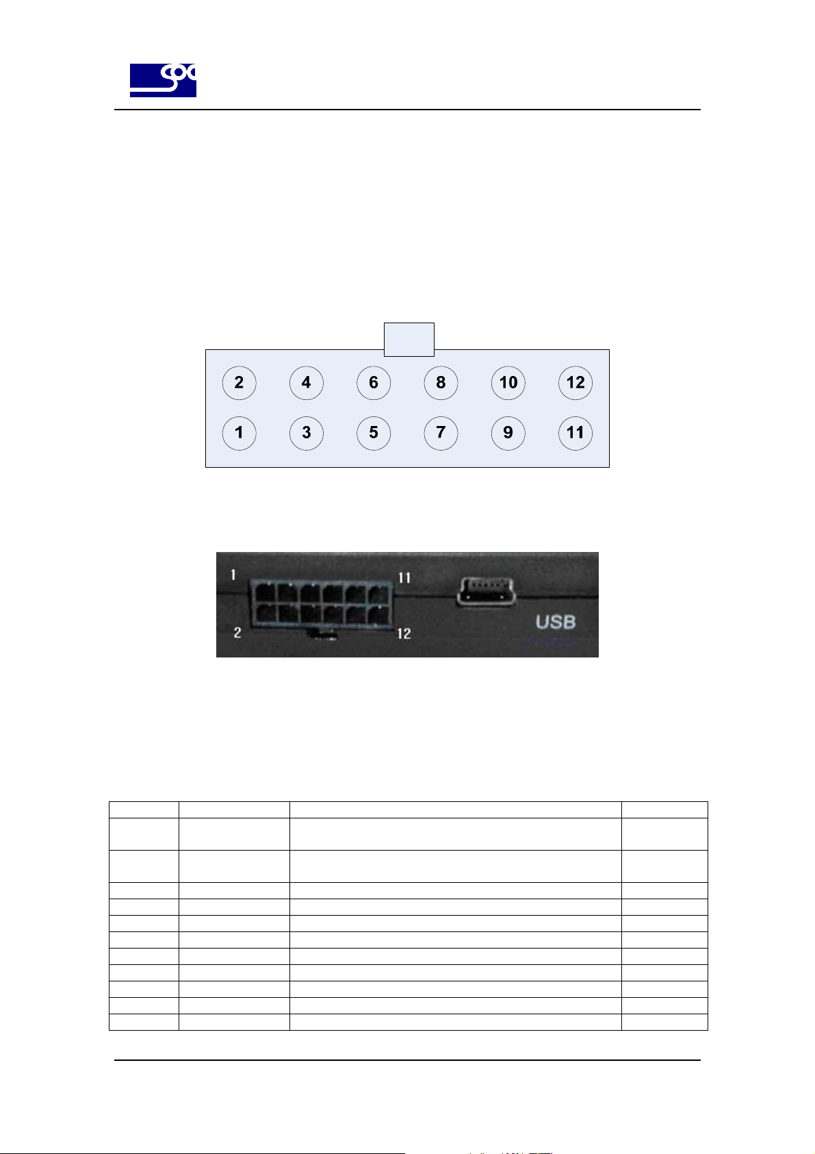
1.3.1. Vehicle interface
LOOK’ET has 12 port signals to interface with vehicle.
1.3.1.1. Vehicle 12 pin interface pin out
SOC LBS LOOK’ET User Manual
Fig 6. Vehicle 12 pin connector cable part
Fig 7. Vehicle 12 pin connector LOOK’ET part
1.3.1.2. Vehicle 12 pin interface pin & cable description
Number Pin name Description Cable color
1 Digital output 1 General purpose output.500 mA max.@ 10 ~ 33V DC
To connect the vehicle, it needs Relay.
2 Digital output 2 General purpose output.500 mA max.@ 10 ~ 33V DC
To connect the vehicle, it needs Relay.
3 Analog input 1 General purpose analog input. Up to 33 V DC/10 bit resolution Yellow
4 Analog input 2 General purpose analog input. Up to 33 V DC/10 bit resolution Yellow
5 Digital input 1 General purpose input. High=10 V ~ 33 V DC, Low=0V Orange
6 Digital input 2 General purpose input. High=10 V ~ 33 V DC, Low=0V Orange
7 Digital input 3 General purpose input. High=10 V ~ 33 V DC, Low=0V Orange
8 IGNITION General purpose input. High=10 V ~ 33 V DC, Low=0V Blue
9 CANH NC. White
10 CANL NC. White
11 VIN Input power for the unit must be 12/24 volts for the unit to Red
Brown
Brown
9
Page 10

SysOnChip
SOC LBS LOOK’ET User Manual
operate properly; A direct connection to the vehicle’s battery is
preferable. The 2A fuse in this cable is to protect the +12/24
volt input to the unit.
12 GND Wire to vehicle ground. Black
Table 1. Vehicle interface pin description table
1.3.2. USB interface
LOOK’ET supports USB 2.0 and mini-USB type connector.
1.3.3. RS232 interface
LOOK’ET supports RS232 to interface with external device like navigation..
Supported signal is RS232Tx,RS232Rx and GND. In normal LBS applications, It does not need to be connected.
1.3.4. External GPS antenna
LOOK’ET has internal GPS patch antenna in itself, but supports external GPS antenna.
1.3.5. External GSM/GPRS antenna
LOOK’ET has two types of GSM/GPRS antenna according to the supported bandwidth.
10
Page 11

SysOnChip
1.3.6. LEDs
LOOK’ET has three LEDs for indicating operation status.
LED name Mark Description
Battery LED
GPS LED
GSM/GPRS LED
It indicates the battery status.
In boot stage after power on, it blinks 4 times with 1 second period indicating boot
completion. If the boot stage has some error, it blinks forever.
After boot stage, It blinks if the battery voltage level is under 3.6V else on.
It indicates the GPS sync status.
This LED is on if the GPS has detected and synced. But GPS does not have
synced and is under searching sync, this LED is blinked.
It indicates the GSM Tx / Rx status.
In boot stage after power on, it blinks 4 times with 1 second period indicating boot
completion. If the boot stage has some error, it blinks forever.
After boot stage,this LED is on when the GSM Tx or Rx operation is executed. LED
is off when LOOK’ET is in Idle mode.
SOC LBS LOOK’ET User Manual
Table 2. LED indications
11
Page 12

SysOnChip
SOC LBS LOOK’ET User Manual
1.4 LOOK’ET basic operation scheme
LOOK’ET has several stages to debug status and operate in test mode.
User does not have to control this, but it is good to know to when the debugging command is valid.
1) Boot stage
After power on, Boot stage takes 25 seconds to check the flash memory status and user program updating request.
If the user want to upgrade LOOK’ET with the new binary file, it can be done in this time.
2) Application stage
After boot stage, application code will be executed. Application code waits 5 seconds to select the test mode before
initialization. If the user does not enter test mode value within 5 seconds, LOOK’ET proceeds the normal operation
mode. This test mode is just for the hardware testing so user does not have to enter this. After this, LOOK’ET does
initialization and waits in idle mode.
Consequently, user must waits the least 35 seconds after power on.
12
Page 13

SysOnChip
SOC LBS LOOK’ET User Manual
2. Security
It is important for the efficient and safe operation to read this information before use LOOK’ET.
This chapter contains important information for the safe and reliable use of the
LOOK’ET. Please read this chapter carefully before starting to use LOOK’ET.
(1) Risk of explosion if battery is replaced by incorrect type. dispose of used batteries according to the instructions.
(2) To minimize the exposure to RF energy, It is recommended to place the antenna more than 20 centimeter from
human body.
(3) Turn your LOOK’ET modem device OFF in health care facilities when any regulations posted in the area instruct
you to do so. Hospitals or health care facilities may be using RF monitoring equipment.
(4) Turn your LOOK’ET device OFF in blasting area when any regulations posted in the area instruct you to do so.
(5) Turn your LOOK’ET device OFF before boarding any aircraft. Use it on the ground only with crew permission. Do
not use it in the air.
(6) Do not allow children to play with your LOOK;ET device. Children could hurt themselves or be damaged with
playing that.
(7) Turn your LOOK’ET device off when in any area with a potentially explosive atmosphere. Modem or its
accessories could generate sparks. Sparks in such areas could cause an explosion or fire resulting in bodily injury or
even death.
(8) The antenna shall be mounted in such a position that no part of the human body will
normally rest close to any part of the antenna. It is also recommended to use the
equipment not close to medical devices as for example hearing aids and pacemakers.
3. Safety standards
This GSM/GPS modem complies with all applicable RF safety standards.
The embedded GSM/GPRS/GPS modem meets the safety standards for RF receivers
and the standards and recommendations for the protection of public exposure to RF
electromagnetic energy established by government bodies and professional organizations, such as directives of the
European Community, in matters of radio frequency electromagnetic energy.
13
Page 14

SysOnChip
SOC LBS LOOK’ET User Manual
4. Basic startup and testing
The SOC LBS LOOK’ET has been made to make installation, testing and configuration simple. For vehicle
installation and testing for correct working after installation we recommend the installer to use a Notebook or Desktop
PC via USB 2.0 interface.
The program for debugging/controlling LOOK’ET is provided in view of both target side and network side.
DM(Diagnostic Monitor) is the target side program and CC(Control Center) is network side program for debugging
and controlling.
Before the LOOK’ET is installed, we recommend configuring the unit functions and setup using the LOOL’ET DM
program including setup configuration. The LOOK’ET has many functions that will allow the unit to operate for
different user applications including security and fleet management.
4.1. Needed accessory and programs
LOOK’ET product has many hardware accessories and software programs to operate correctly.
No. Component name Quantity Remarks
1 LOOK’ET body 1 ea. Hardware.
2 External GPS antenna 1 ea. Hardware.
3 External GSM/GPRS antenna 1 ea. Hardware.
4 12 Pin Vehicle interface connector & cable 1 ea. Hardware.
5 Internal battery 1 ea. Hardware.
6 USB mini-type connector & cable 1 ea. Hardware.
7 RS232 connector & cable Not included. Hardware.
8 Tray for Fix LOOK’ET 1 ea. Hardware.
9 USB Driver install file 1 set. Software.
10 DM(Diagnostic Monitor) Program 1 set. Software.
11 CC(Control Center) Program 1 set. Software.
12 UPGS(Update Server) Program 1 set. Software.
Fig 8. Hardware/Software accessories
14
Page 15

SysOnChip
4.1.1. Hardware accessories
1) LOOK’ET body
Fig 9. Hardware Accessory : Body
SOC LBS LOOK’ET User Manual
2) External GPS antenna
Fig 10. Hardware Accessory : External GPS antenna
3) External GSM/GPRS antenna
Fig 11. Hardware Accessory : External GSM/GPRS antenna
15
Page 16

SysOnChip
4) 12 Pin Vehicle interface connector & cable
Fig 12. Hardware Accessory : vehicle 12 pin connector & cable
5) Internal battery
SOC LBS LOOK’ET User Manual
Fig 13. Hardware Accessory : Internal battery
6) USB mini-type connector & cable
Fig 14. Hardware Accessory : USB mini-type connector & cable
16
Page 17

SysOnChip
7) RS232 connector & cable
None. Not needed.
8) Tray for Fix LOOK’ET
SOC LBS LOOK’ET User Manual
Fig 15. Hardware Accessory : LOOK’ET tray(Cradle)
17
Page 18

SysOnChip
SOC LBS LOOK’ET User Manual
4.1.2. Software programs
1) USB Driver install file
USB driver installation is needed to connect the LOOK’ET with PC. After completed installing the USB driver, hyper
terminal and DM can be used to control and debug the LOOK’ET.
Refer to the document [1] and [3] for detail description to install USB driver and DM.
2) DM(Diagnostic Monitor) Program
LBS_DM.exe, configuration text file and several DLL files are provided by SOC. These files must be copied together
in one directory of your DM PC. Just execute LBS_DM.exe to invoke the DM program.
Refer to the document [3] for detail description for DM.
3) CC(Control Center) Program
LBS_CONTROL_CENTER.exe, configuration text file and several DLL files are provided by SOC. These files must
be copied together in one directory of your control center PC. Just execute LBS_CONTROL_CENTER.exe to invoke
the DM program.
Refer to the document [3] for detail description for CC.
4) UPGS(Update Server) Program
LBS_REMOTE_UPGRADE_SERVER.exe, binary LOOK’ET file and several DLL files are provided by SOC.
Binary LOOK’ET file must be placed in the C:\LBS_FLASH_FILE directory and other exe and DLL files must be
copied together in one directory of your upgrade server PC.
Refer to the document [4] for detail description for upgrade server.
18
Page 19
SysOnChip
SOC LBS LOOK’ET User Manual
4.2. Testing environment & Installation
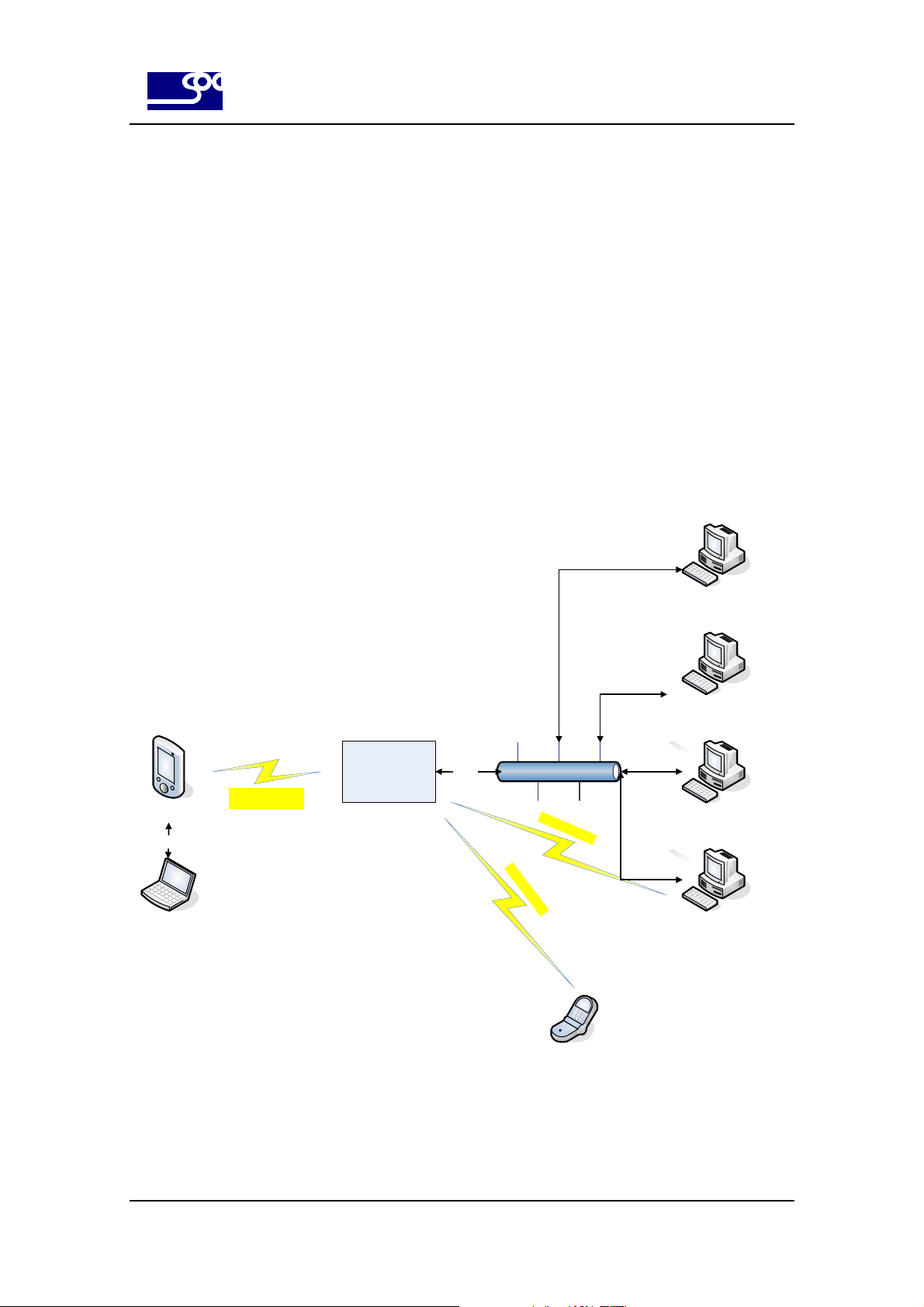
4.2.1. Testing environment
The testing environment of LOOK’ET is as followings.
Basic period report message, which is occurred by period during ignition on or off, is reported to the control center.
History report & logging message can be checked at DM and control center at any time during GPRS connection is
established. Also daily history report can be sent E-mail server or other GPRS server by configuration setting.
Program updating can be executed at DM and Upgrade server. Alarm messages can be transferred to the specified
SMS user by configuration setting. To test this basic environment, DM and GPRS capable Control center and
upgrade server software will be provided by SOC.
LOOK’ET
USB
DM
RF : GPRS Packet/
GSM SMS
GSM/GPRS
Network
GPRS
Internet network
R
F
:
G
S
M
S
MS
R
F
:
G
S
M
S
M
S
E-mail or Other
GPRS Server
Upgrade Server
SW
Control Center
(GPRS capable)
Control Center
( GPRS / GSM capable)
Pre-defined
SMS user
Fig 16. Operation environment
19
Page 20

SysOnChip
4.2.2. Installation & Usage
4.2.2.1. Component connection
(1) Connect the external GSM antenna and external GPS antenna
SOC LBS LOOK’ET User Manual
(2) Connect the USB connector LOOK’ET and PC.
(3) Connect the 12 pin vehicle interface connector LOOK’ET and Vehicle.
The VIN,GND and IGNITION signals of vehicle interface must be connected to the vehicle. If this signals are not
connected with vehicle, use power supply or 12V/24V battery.
20
Page 21
SysOnChip
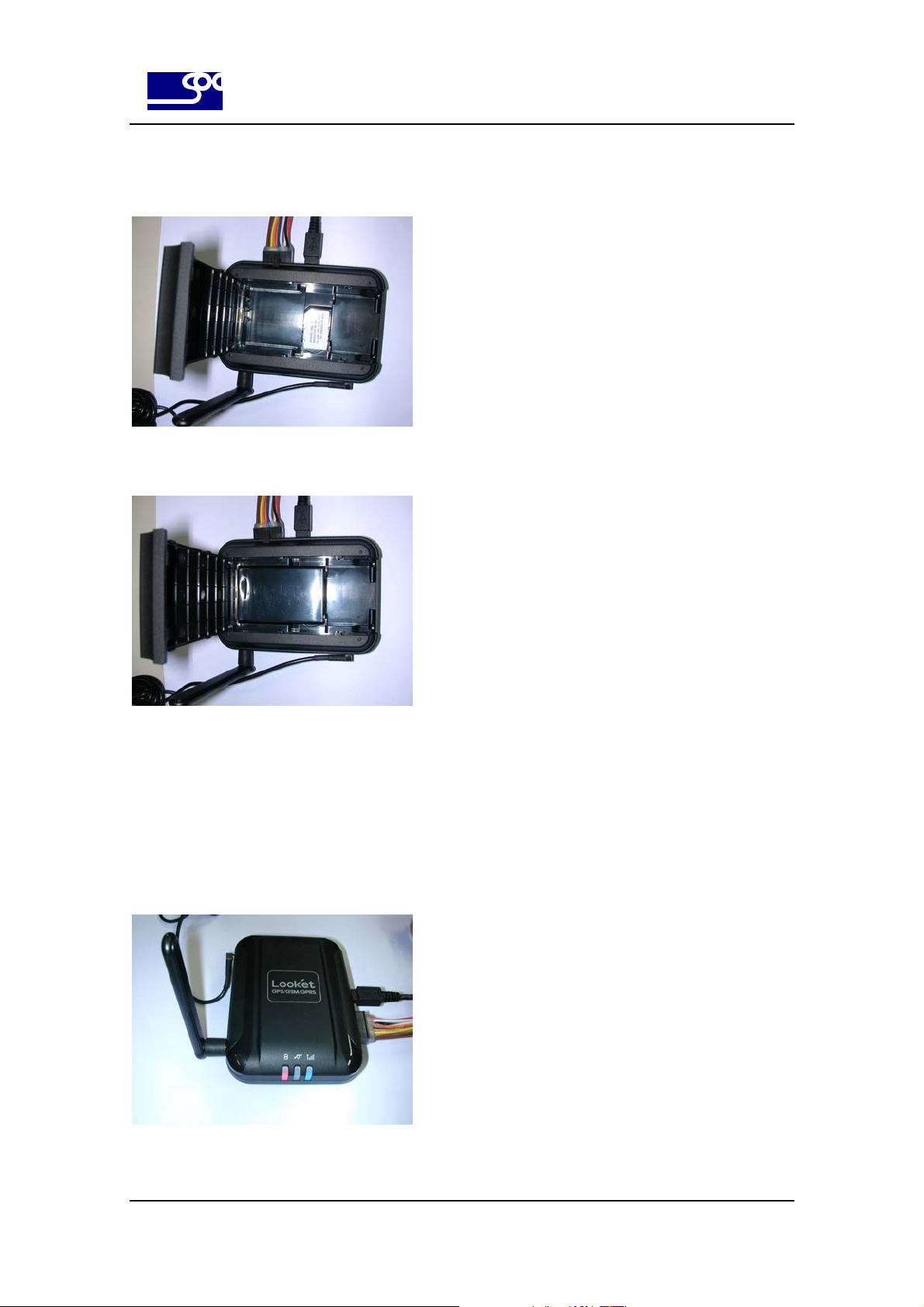
(4) Open the rear cover and insert the SIM card.
(5) Insert the Internal battery. Inserting internal battery means the power On.
SOC LBS LOOK’ET User Manual
(6) You can execute “CONNECT” in the DM program.
You can see the processing status.
(7) After about 25 seconds, Boot process is completed, LEDs for GSM and Power will be blinked 4 times.
Then LOOK’ET will process the application code. Application code will initialize its configuration and goes to the idle
state. User must wait for 35 seconds to enter debugging or control commands.
21
Page 22

SysOnChip
4.2.2.2. USB driver installation & test
Refer to the document [1] for detail description.
4.2.2.3. DM installation
Refer to the document [1] for detail description.
4.2.2.4. Configuration setting by DM
Refer to the document [3] for detail description.
4.2.2.5. Confirm the connection with control center
Refer to the document [2] for detail description.
SOC LBS LOOK’ET User Manual
4.2.2.6. Program updating
Program updating using DM is described in the document [3].
Program updating using Upgrade server is described in the document [4].
22
Page 23

SysOnChip
5. Specification
5.1. Software features
z SMS mode/GPRS mode/SMS+GPRS mode
z Position request via SMS or GPRS
z Auto position logging or reports, based on configurable time or distance interval
z Data logging capacity : up to Max. 1,440 point
z Upload/download settings, locations, and update firmware via GPRS.
z Configurable GEO-fencing
z Configurable 3 digital inputs for alert messaging
z 2 analog inputs for alert messaging
SOC LBS LOOK’ET User Manual
z Configurable 2 digital outputs for remote control of vehicle
z Combination of GSM network based tracking and GPS tracking possible
5.2. Hardware features
z GSM/GPRS Core
Siemens MC55 : 900/1800/1900 MHz
Siemens MC56 : 850/1800/1900 MHz
z GSM/GPRS services
Data, SMS/ GPRS class B, class 10, TCP IP
z Physical characteristics
Dimensions( L x W x H ) : 104 x 73 x 29.8 mm
Weight : approx. 160 g (Including internal battery )
z Temperature range
Operation: -20°C to +70°C
Storage temperature -40°C to +80°C
z Power sources
Input Voltage: 10~32 Volt DC regulated / Max. 2A
Rechargeable & replaceable Li-ion Battery 1800 mAh
z Interfaces
12-pin vehicle I/O interface :
USB connector interface
Serial RS232C Interface
23
Page 24
SysOnChip
z Antenna
Default GPS patch antenna
External GSM/GPRS antenna
Optional external boost GPS antenna
z Indication
3 LED’s for GSM/GPRS and GPS status
z Certificate
Compliant with the EU RoHS Directive
SOC LBS LOOK’ET User Manual
CE, FCC, E-mark
5.3. Technical specification
z GSM/GPRS modem specification
Frequency bands MC55 Tri-band : EGSM 900, DCS 1800, PCS1900
GSM class Small MS
Transmit power Class 4 (2W) at EGSM900 and GSM850
GPRS connectivity GPRS multi-slot class 10
DATA GPRS Data up/ downlink transfer: max. 85.6/ 42.8 kbps
DATA CSD
SMS SMS, MT, MO, CB, Text and PDU mode
TCP/IP stack Internet services :
FAX Group 3 : Class 1, Class 2
SIM interface Supported SIM card: 3V
MC56 Tri-band : GSM 850, DCS 1800, PCS 1900
Compliant to GSM Phase 2/2+
Class 1 (1W) at DCS1800 and PCS 1900
GPRS mobile station class B
Coding scheme: CS-1, CS-2, CS-3 and CS-4
Supports the protocols PAP and CHAP commonly
used for PPP connections.
Support Packet Switched Broadcast Control
Channel (PBCCH)
CSD transmission rates: 2.4, 4.8, 9.6, 14.4 kbps,
non-transparent
Unstructured Supplementary Services Data
(USSD) support
SMS storage: SIM card and 25 SMS locations in
the mobile equipment
Support transmission of SMS alternatively over
CSD or GPRS.
User can choose preferred mode.
TCP,UDP,HTTP,FTP,SMTP,POP3
Table 3. GSM/GPRS module specification
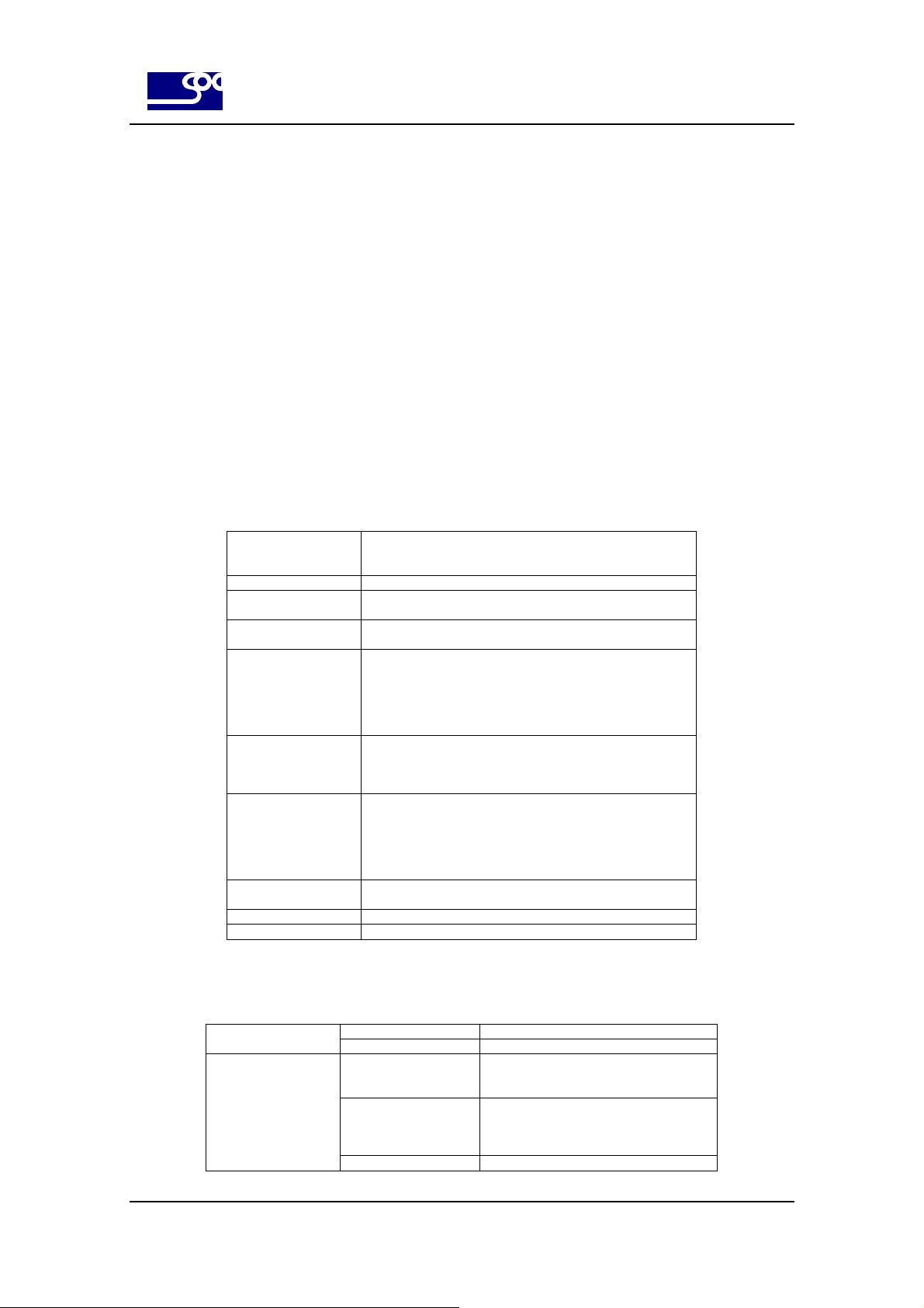
z GPS module specification
Receive frequency 1.57542 GHz +/- 1.023 MHz General
GPS datum WGS-84
SiRFstar III chipset
Acquisition Rate Conventional mode
Accuracy Position: 10 meters CEP without SA
Channel
20-channel GPS
Cold/ Warm/ Hot start < 42/ 38/ 1 sec
( 95 % typical)
Velocity: 0.1 meters/second, without SA
Time: 1 microsecond synchronized to
GPS time
24
Page 25

SysOnChip
SOC LBS LOOK’ET User Manual
Table 4. GPS module specification
25
Page 26

SysOnChip
6. History
Document history
V 0.9 Sep.28, 2007 star4u Document creation.
V 0.91 Oct.11, 2007 star4u Added chapter 2(Security) description
Added chapter 3(Safety standards) description
Added vehicle interface pin out.
SOC LBS LOOK’ET User Manual
26
 Loading...