


Scalibur – Modular Controllers
SCA-340 / SCA-340-L
Manual
Rev.22

Disclaimer / Impressum
This manual is intended to provide support for installation and usage of the device. The
information is believed to be accurate and reliable. However, SysMik GmbH Dresden
assumes no responsibility for possible mistakes and deviations in the technical
specifications. SysMik GmbH Dresden reserves the right to make modifications in the
interest of technical progress to improve our modules and software or to correct mistakes.
We are grateful to you for criticism and suggestions. Further information (device description,
available software) can be found on our homepage www.sysmik.de. Please ask for latest
information.
SysMik disclaims all warranties in case of improper use or disassembly and software
modifications not described in this document or when using improper or faulty tools.
Commissioning and operation of the device by qualified personnel only. All applicable
regulations have to be observed.
SysMik
All other trademarks mentioned in this document are registered properties of their owners.
These and further trademarks are used in this document but not marked for better
readability.
No part of this document may be reproduced or modified in any form without prior written
agreement with SysMik GmbH Dresden.
Copyright © 2018 by SysMik GmbH Dresden
SysMik GmbH Dresden Tel + 49 (0) 351 – 4 33 58 – _0
Bertolt-Brecht-Allee 24 Fax + 49 (0) 351 – 4 33 58 – 29
01309 Dresden E-Mail (Sale) sales@sysmik.de
E-Mail (Support) service@sysmik.de
Germany Homepage https://www.sysmik.de
®
and the SysMik logo are registered trademarks of SysMik GmbH Dresden.
2 sysmik.de Manual SCA-340 / SCA-340-L

Contents
Contents
1. Introduction 6
2. Device and System Overview 7
2.1 Hardware 7
2.1.1 Functional Overview 7
2.1.2 Processor Core 7
2.1.3 Ethernet 7
2.1.4 Serial Ports 8
2.1.5 USB 8
2.1.6 LON 8
2.1.7 Inline Local Bus Interface / Modular IO Terminals 8
2.2 Software Overview 9
2.2.1 Scalibur System Shell 9
2.2.2 IO Server 9
2.2.3 Commissioning Web Server 9
2.2.4 Sedona Virtual Machine 9
2.2.5 Niagara Framework 10
3. Installation and Commissioning 11
3.1 Assembly 11
3.1.1 Dimensions 11
3.1.2 Mounting 12
3.1.3 Adding Inline Terminals 13
3.2 Connections 14
3.2.1 Connectors 14
3.2.2 Power Supply 15
3.2.2.1 How to Connect Power 15
3.2.2.2 Power Dissipation Calculations for a Scalibur Controller 17
3.2.2.3 Current Consumption Calculation for a Scalibur Station (with Terminals) 18
3.2.2.4 Derating of Terminal and USB Supply 18
3.2.2.5 Protective Devices of 24 V Main and Segment Supply UM and US 20
3.2.3 RS-485 and LON 20
3.2.4 Ethernet 21
3.2.5 USB-OTG for local Access 22
Manual SCA-340 / SCA-340-L sysmik.de 3

Contents
3.2.6 USB 23
3.3 Operating Elements 24
3.3.1 Overview 24
3.3.2 Inline Supply LEDs “US”, “UM”, “UL” 24
3.3.3 Process Status LEDs “PL”, “ST”, “SE” 24
3.3.4 IO Status LED “IO” 25
3.3.5 Communication LEDs “COM1”, “COM2”, “LON” 25
3.3.6 Service Button and LED “SV” 26
3.3.7 Ethernet Status LEDs 26
3.3.8 RS-485 Termination 27
4. Software 28
4.1 Configuration Tools 28
4.1.1 SCA System Shell 29
4.1.2 Commissioning Website 29
4.1.3 File Access via FTP 30
4.2 Commissioning Scalibur 30
4.2.1 IP Addressing 31
4.2.2 Time and Time Zone 31
4.2.3 Hardware Data Point Test 31
4.3 Ethernet Switch for Flexible Network Topologies 33
4.3.1 Assignment of IP Interfaces to External Ethernet Ports 33
4.3.2 Ethernet Ring Monitoring 35
4.3.3 Rapid-Spanning-Tree-Protocol (RSTP) 35
4.3.4 Port Status Informations 36
4.3.5 Broadcast Storm Protection 36
4.4 Real-Time Control with Scalibur and Sedona 37
4.4.1 IO Access 37
4.4.2 Modbus 37
4.4.3 Platform Service 38
4.5 Integration with Scalibur and Niagara Framework 39
4.5.1 Local IO Access 39
4.5.2 Serial Interfaces 41
4.5.3 IO Remote Control 43
4.5.4 Sedona Integration 43
4 sysmik.de Manual SCA-340 / SCA-340-L

Contents
4.6 Concurrent Access to the IO Terminals 44
5. Best Practices and Troubleshooting 46
5.1 Performance and Resource Management 46
5.2 Reliability of Nonvolatile Memory 47
5.3 Diagnosis and Troubleshooting 47
5.3.1 SCA System Shell / Commissioning Website is not accessible 48
5.3.2 IP Address unknown 48
5.3.3 No IP Communication 48
5.3.4 Unknown Niagara Platform Access Credentials 48
5.3.5 No Platform Connection to Device - Platform Daemon is not starting 49
5.3.6 Sedona Virtual Machine is not Starting 49
5.3.7 IO Errors 49
6. Technical Data 50
7. Order Information 53
7.1 Scalibur and Accessories 53
7.2 Supported Inline Automation Terminals 54
8. Glossary 56
9. Third-Party Software 57
10. Bibliography 58
Manual SCA-340 / SCA-340-L sysmik.de 5

Introduction
1. Introduction
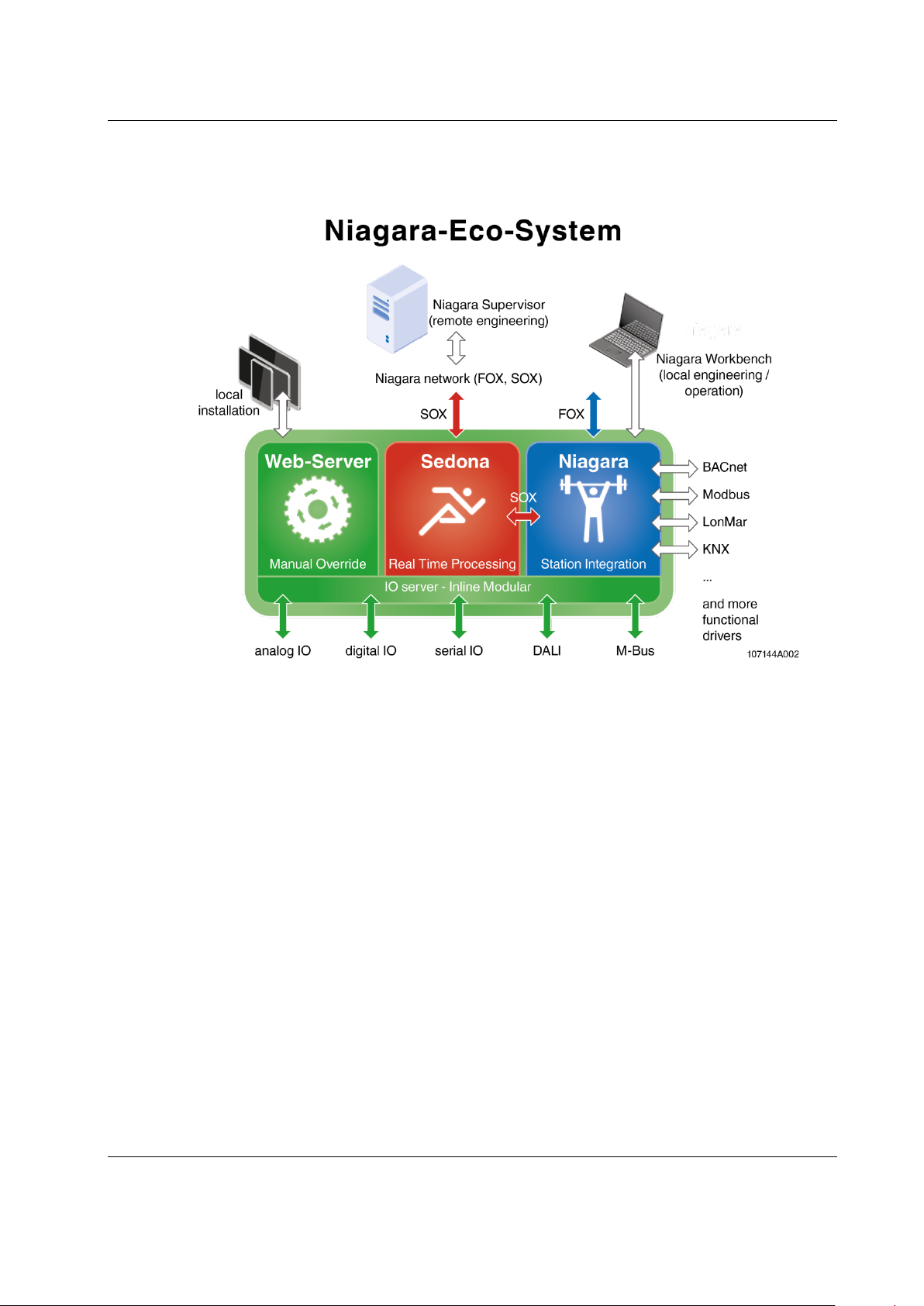
Scalibur is a powerful modular controller for Niagara and Sedona. Scalibur stands
for scalability, a major characteristic of this controller. Scalability comprises several
aspects:
1) Scalable IO
A Scalibur station consists of the Scalibur controller and up to 63 terminals of the
modular Inline system. The terminals are available in a wide variety of types:
digital and analog inputs and outputs with different numbers of channels as well
as functional terminals for DALI light control, pulse metering, MBUS or serial
interfaces.
2) Scalable software
Scalibur has been developed primarily for the Niagara framework. Niagara
applications are built with the software tool Niagara Workbench. While Niagara
is very powerful, it is not very well suited for specific real-time applications. In
order to realize such applications with Scalibur too, the controller has the
Sedona framework in parallel to Niagara. Sedona applications run with fixed
cycle times in the millisecond range and are created with the
Niagara Workbench. Beside the separate exclusive use of either framework, the
parallel use of Niagara and Sedona is supported. The Niagara and Sedona
application can communicate to each other with a Sedona driver for Niagara.
3) Scalable licensing
The license model for Scalibur is very flexible: a license comprises a certain
number of data points which can be integrated with Scalibur. These license
packs are available as first-time license (250/500/1250/5000/10000 data points)
or as upgrade license (500/1250/2500 data points). Sedona, as open source
project, doesn’t have any license fees.
4) Scalable IP network
Scalibur contains two logically separated IP interfaces and an integrated
Ethernet switch with four external ports. The configurable assignment of the
Ethernet ports to the separate IP interfaces and the usage of the spanning-treeprotocol allow flexible topologies like daisy-chain and redundant ring-structures
for both the backbone and the local control network.
6 sysmik.de Manual SCA-340 / SCA-340-L

2. Device and System Overview
2.1 Hardware
2.1.1 Functional Overview
Device and System Overview
Fig. 2.1.1.1: SCA-340-L basic circuit diagram
2.1.2 Processor Core
Processor: ARM® Cortex® A8 / 1 GHz
DDR3 SDRAM: 1 GB RAM (512 MiB for hardware version < 06 – see serial label)
eMMC Flash: 1,8 GB
NVRAM: 512 KiB / (buffered for a power failure of 5 days)
RTC: buffered for a power failure of 5 days
The internal Flash memory can be extended with a microSD card.
2.1.3 Ethernet
The integrated Ethernet switch has 4 external ports, which can be assigned
independently to one of the two separate IP interfaces. If at least two ports belong to
an IP interface, then redundant communication paths can be established, for
example by connecting several devices in a ring. The Ethernet switch supports the
Rapid Spanning Tree Protocol (RSTP), as well as a ring monitoring function to
automatically switch off redundant paths, and a broadcast storm protection function.
Factory default: eth0 is assigned to LAN3/LAN4, eth1 is assigned to LAN1/LAN2,
and RSTP and ring monitoring are deactivated.
Manual SCA-340 / SCA-340-L sysmik.de 7

Device and System Overview
2.1.4 Serial Ports
Both RS-485 ports have switches for bias and terminating resistors, and are
galvanically isolated from each other and the rest of the circuit.
Further serial interfaces may be added using modular IO terminals (M-Bus, RS-232,
RS-485, RS-422).
2.1.5 USB
USB 1 is a USB-OTG port with Mini-USB socket, and is used for installation and
maintenance. Connected to a PC, it allows to control the device via console and to
access the internal installation web site for device configuration and data point test.
The second USB port (USB 2) allows to connect USB end-devices.
2.1.6 LON
The SCA-340-L has a LON interface according to the CEA-709 standard, to connect
directly to LonMark TP/FT-10 networks.
2.1.7 Inline Local Bus Interface / Modular IO Terminals
The local bus interface allows to connect up to 63 modular IO terminals. This
interface comprises the communication channel to the IO terminals as well as the
power supply of these terminals and their connected sensors and actuators.
Scalibur is a controller for the Inline IO system and unlocks the rich pool of Inline IO
terminals for building automation.
Inline is a modular IO system by Phoenix Contact, to flexibly and quickly build up
space-saving automation stations. An Inline station consists of a bus controller and
a set of IO terminals, chosen freely in terms of numbers, type, and sequential
arrangement. The bus controller runs the Inline station and has interfaces to the
higher level controller. Up to 63 IO terminals can be connected to a bus controller.
There are IO terminals for almost any purpose:
digital inputs and outputs with 1, 2, 4, 8, 16, or 32 channels per terminal
Triac and relay outputs for switching signals or for higher loads
analog inputs for measuring voltage, current, resistance, or temperature
with 2, 4, or 8 channels per terminal
analog outputs for voltage or current with 2, 4, or 8 channels per terminal
function terminals for complex IO operations or gateway functions (DALI,
M-Bus, S0 pulse metering, serial interface)
supply and support terminals , e.g. to realize separated voltage domains
within an Inline station
The overall width of the Inline extension terminals is 1, 2 or 4 DU (1 DU, division
unit = 12.2 mm or approx. 0.48 in.).
Inline terminals are provided with a pluggable wiring level enabling pre-wiring and
easy module exchange.
The mechanics of the system also allows exchanging terminals without complete
dismantling of the station.
Scalibur determines type and function of all supported terminals automatically, thus
certain in- and output functions can also be created without a previous configuration
of the station, which is especially helpful for commissioning tests.
8 sysmik.de Manual SCA-340 / SCA-340-L
2.2 Software Overview
Scalibur is using a Linux operating system, which runs several applications in
parallel.
Device and System Overview
Fig. 2.1.7.1: Scalibur software structure
2.2.1 Scalibur System Shell
The Scalibur System Shell is accessible only via the local USB-OTG port, and is
used during commissioning to configure basic settings like IP address, or as
maintenance access if IP address or passwords have been lost.
2.2.2 IO Server
The IO server controls the modular Inline terminals of the Scalibur station and
manages concurrent accesses to the hardware data points. Niagara and the IO
server communicate via an TCP connection. This allows to control IOs remotely
from another Niagara station. The remote access can be limited or disabled by the
setting of the IP address of the controlling station.
2.2.3 Commissioning Web Server
The commissioning web server is exclusively accessible via the local USB-OTG
port. It presents web pages to commission the device: setting IP addresses and time
zone, reading state of inputs and setting output states of the data points of the local
IO terminals for test purposes.
2.2.4 Sedona Virtual Machine
The Sedona virtual machine (SVM) runs the Sedona application in real-time with
configurable cycle time. The Niagara Workbench connects to the SVM to modify the
application, load updates, or create backups of the application. Platform specific kits
provide access to the IO terminals, and also to system settings like IP addresses
Manual SCA-340 / SCA-340-L sysmik.de 9

Device and System Overview
and Modbus settings. A Modbus TCP server and a Modbus TCP client/Modbus RTU
master are integrated and are used to exchange data with other Sedona controllers.
Also, Niagara can be deactivated here.
2.2.5 Niagara Framework
Scalibur can be parameterized with Niagara Workbench and a platform connection
to the Niagara daemon. This includes loading of software updates and of a station
(Niagara application), which can be run automatically by the Niagara daemon.
A Workbench connection to a station is used to modify the station. All features of the
Niagara framework are available:
data point integration over a plethora of open automation protocols (LON,
BACnet, KNX, M-Bus, Modbus, and others) with data normalization
system functions (scheduler, alarming, trend log)
web visualization
enterprise interfaces (oBIX, data bases) and many more
10 sysmik.de Manual SCA-340 / SCA-340-L

3. Installation and Commissioning
3.1 Assembly
3.1.1 Dimensions
Width x Height x Depth:
80 mm x 119,8 mm x 71,5 mm (3.15 inch x 4.72 inch x 2.81 inch)
Installation and Commissioning
Fig. 3.1.1.1: Scalibur dimensions
Manual SCA-340 / SCA-340-L sysmik.de 11

Installation and Commissioning
3.1.2 Mounting
Preferred mounting position is horizontal (i.e. on a horizontal DIN rail which is
attached to a vertical wall). For all other mounting positions, a derating has to be
observed (see chapter 6).
Note: The air vents have to be kept free with a sufficient spacing to other components, to
ensure optimal air ventilation.
The device is designed for easy snap in mounting on 35 mm x 7.5 mm
DIN EN 60715 rails (formerly DIN EN 50022).
Note: The DIN rail should be attached to a mounting plate or an even back plane for best
stability.
Suitable fixtures, like end clamps or grounding terminals have to be used at both
ends of the station, to prevent sliding off the rail.
Note: To ensure easy unlocking of the Ethernet connectors, use only clamps at the bus
controller side of the station that do not protrude more than 30 mm from the rail.
Note: Only use clean and corrosion free mounting rails in order to ensure a safe contact
between the FE terminals.
12 sysmik.de Manual SCA-340 / SCA-340-L

3.1.3 Adding Inline Terminals
6452B010
An Inline station is assembled by plugging the individual components to each other,
thus establishing the potential and bus signal connection between the individual
components of the station. Figure 3.1.3.1 shows the procedure of mounting a
terminal.
Disconnect power to the entire station.
Mount the electronics base onto the rail (A). Adjacent terminals are
interlocked by their feather keys / keyways (B).
First insert the feather keys of the local bus into the keyways of the
preceding terminal (B1).
Guide the feather keys along the keyways until they lock appropriately
(B2).
Ensure that the feather keys are properly connected (C2). C1 shows the
common mistake that the feather keys are not inside their keyways.
After mounting all electronics bases install the connectors onto their
respective bases. First insert the front detent (D1). Then push the
connector onto the electronics base until the rear detent locks properly
(D2).
Installation and Commissioning
Figure 3.1.3.1: Installation on the mounting rail (A), connection of Inline components to each other (B),
connection check (C), plugging of the wiring level (D)
Note: While connecting the components to each other and to the mounting rail later, please
make sure that all feather keys and latches are properly snapped in!
Note: Please consult the User Manual with regard to configuration and installation of the
Inline product family (see [1]).
Manual SCA-340 / SCA-340-L sysmik.de 13

Installation and Commissioning
1
Micro-SD card slot
8
Switches for RS-485 termination / bias
2
Type label with device-specific
information
9
Service interface
3
Service button
10
Bus interface connector
4
Ethernet (4x 10/100BaseT)
11
Supply connector
5
FE connector *)
12
Labeling field (2x)
6
USB 1 (mini USB, USB-OTG)
13
Diagnostic indicators
7
USB 2
14
End plate
*) … The FE connector is placed at the rear side of the connector – it is not visible in the
sketch.
3.2 Connections
3.2.1 Connectors
Fig. 3.2.1.1: Overview device connections
14 sysmik.de Manual SCA-340 / SCA-340-L

3.2.2 Power Supply
3.2.2.1 How to Connect Power
The bus controller is operated with 24 V DC. The bus controller is powered from this
source and it generates the logic voltage for the logic circuit and the analog voltage
for the analog circuit. The logic circuit supplies the internal bus including the
communication chips of all connected automation I/O terminals. The analog circuit
provides an auxiliary supply for analog signals.
Note: While connecting the automation terminals please observe the derating of the logic
voltage, the supply of the analog terminals, and the maximum ampacity of the terminals.
Furthermore the bus controller includes connections for the supply of the mains and
segment voltage of the Inline station.
Fig 3.2.2.1 shows the basic circuit for the connections of the power supply.
Installation and Commissioning
Fig. 3.2.2.1: Supply of U
Note: If UBK/UM and US are to be supplied from a common source, the fuse protection of the
individual sections with regard to their supply requirements has to be observed.
/ UBK and US from different sources (A) and from a common source (B)
M
Note: The current passing through terminals and potential routing contacts must not exceed
8 A.
Manual SCA-340 / SCA-340-L sysmik.de 15

Installation and Commissioning
The Functional Earth ground FE is connected to the potential routing contacts and is
automatically grounded if the bus controller is snapped on a grounded mounting rail.
The function of FE is to discharge interferences.
Note: Functional earth ground (1.4 and. 2.4) has to be connected additionally via 1.5 mm²
wire (AWG 15) and grounding terminal to the mounting rail (see Fig. 3.2.2.2).
Fig. 3.2.2.2: Connecting functional earth ground (FE) of Scalibur
16 sysmik.de Manual SCA-340 / SCA-340-L

Terminal
point
Name Function
24 V DC segment supply (segment circuit); The supplied voltage
contacts.
UBK: 24 V DC bus controller supply, logic supply (UL) and analog
contacts
Reference ground for the internal bus and automation terminals
(main and segment circuit).
Functional ground; Connecting the functional ground to this
contact at the back side of the enclosure.
Installation and Commissioning
1.1 US
2.1
1.2, 2.2
1.3, 2.3 GND
1.4, 2.4 FE
Table 3.2.2.1.1: Terminal assignment of supply connector
U
/ UM
BK
is lead to the automation terminals via the potential routing
supply (U
UM: 24 V DC main voltage (main circuit); The supplied voltage is
lead to the automation terminals via the potential routing
(logic and analog circuit) and for the main and segment supply
terminal point is mandatory (see above). The terminal point is
internally connected to the potential routing contacts and the FE
ANA
)
3.2.2.2 Power Dissipation Calculations for a Scalibur Controller
The power dissipation of the bus controller equals the sum of the power
requirements of the bus controller itself and the power loss of the internal power
supply for the whole Inline station:
P
SCA
= PO+ P
P
SCA
P
O
USB
+ P
PERI
power dissipation of the bus controller
power requirements for operating the bus controller without
terminals and any external load (4.1 W)
P
power dissipation of the bus controller caused by the load on
USB
USB1 and USB2 (max. 500 mA each)
P
= 0.7 V × ( I
USB
P
power dissipation of the bus controller caused by the Inline IO
PERI
USB1
+ I
USB2
)
terminals
P
= 1.0 V × I
PERI
L
IL current consumption of UL
Note: The factors 1.1 V und 0.7 V result from the electrical efficiency of the internal power
supply unit.
Sample calculation: Power dissipation of a Scalibur in case of the maximum
possible current drawn from U
consumption.
P
= 4.1 W + 0.7 V × 0.1 A + 1.0 V × 2.0 A
SCA
P
= 4.1 W + 0.07 W + 2.0 W
SCA
P
= 6.17 W
SCA
Manual SCA-340 / SCA-340-L sysmik.de 17
and a USB memory stick with 0.1 A current
L

Installation and Commissioning
3.2.2.3 Current Consumption Calculation for a Scalibur Station (with Terminals)
To find a suitable external power supply, the current consumption of the entire
Scalibur station has to be considered:
= I
I
IS
SCA
+ I
USB
+ IK + I
AS
IIS current consumption of the entire Scalibur Inline station
I
current consumption of the Scalibur
SCA
I
current consumption of connected USB devices
USB
I
current consumption of connected terminals
K
I
current consumption of sensors and actuators, fed by the Inline station
AS
The current consumption of a Scalibur (without terminals) is maximum 170 mA.
I
= 0.17 A
SCA
Please consult the manual of the connected USB device to find out the actual
current draw from USB.
The respective USB currents IUSB1 and IUSB2 are weighted by a factor of 0.24,
resulting in the equation:
I
USB
= (I
USB1
+ I
USB2
) × 0.24
The current consumption of the connected terminals can be found in their manuals.
The following rules of thumb apply:
The current provided by U
The current provided by U
influences the total current directly.
ANA
applies to the total current with a factor of 0.36.
L
The following formula applies:
I
= IA + IL × 0.36
K
IA current from U
I
current from UL (max. 2.0 A)
L
(max. 500 mA)
ANA
See the according datasheets in order to determine the current consumption of the
connected actuators and sensors.
For an estimation it is often sufficient to check, whether the supply can be provided
completely by the Scalibur, that is without power or boost terminals.
Without power and boost terminals and regardless of the circuits U
und US, the
M
maximum current consumption of the Scalibur with connected terminals is 1.7 A.
In addition there are the current requirements of the sensors and actuators, whereas
the current through feather keys and keyways is limited to a maximum of 8 A.
Note: When selecting an external power supply, plan sufficient reserves. also into account
that it could come to a current increase to a multiple of the rated current in the moment of
turn-on caused by input capacities. Power supplies with over current shut-down must have a
sufficient response delay to avoid start-up problems.
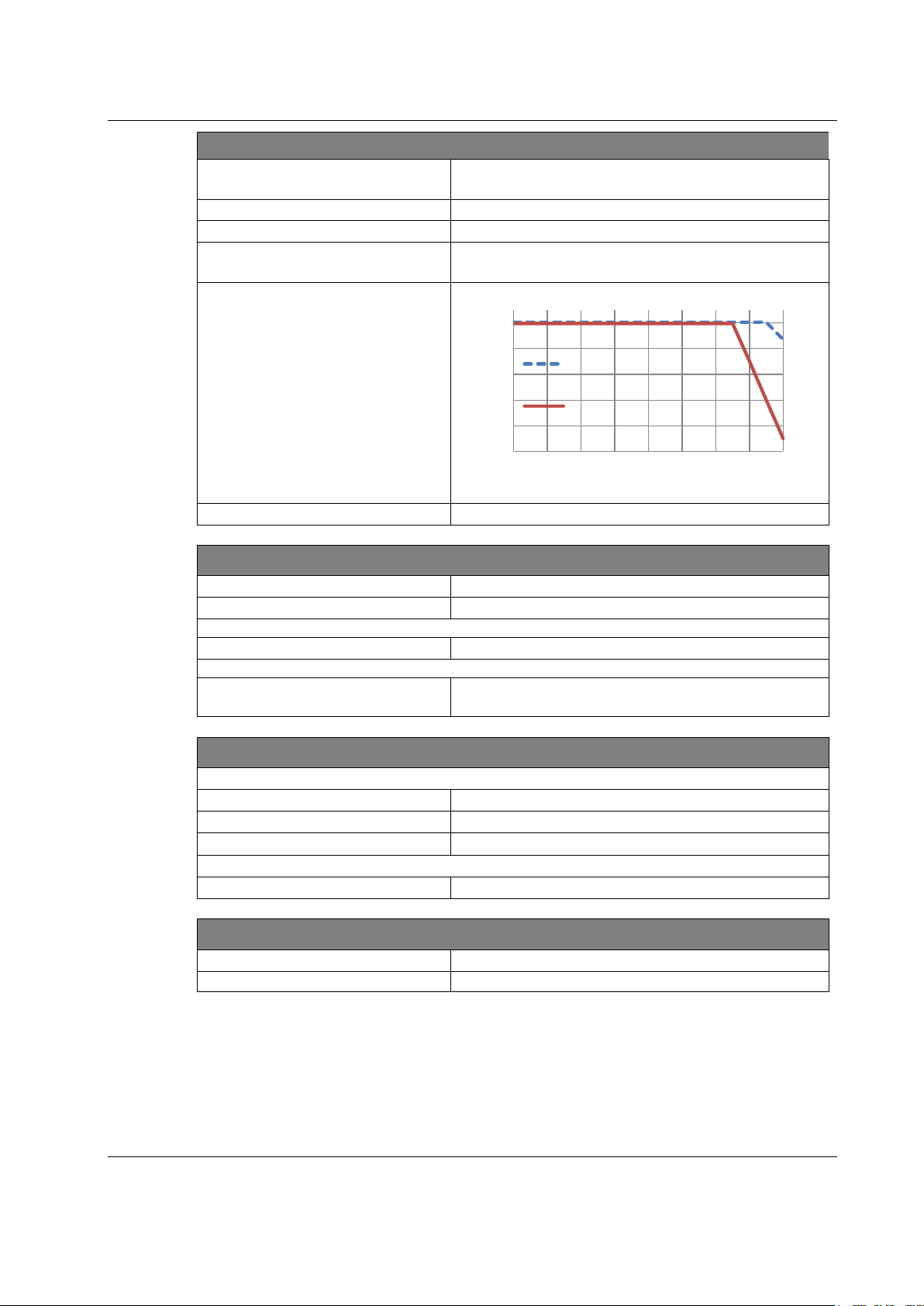
3.2.2.4 Derating of Terminal and USB Supply
Because USB and the Inline terminals are supplied by Scalibur’s internal power
supply unit, an increased load there increases Scalibur’s internal power dissipation.,
Therefore, a derating has to be observed, which is depending on the mounting
position (see Fig. 3.2.2.4). The recommended mounting position (with least derating)
is horizontally (that is, clipped to a horizontal DIN rail on the wall).
The internal power dissipation caused by USB loads (P
terminals (P
18 sysmik.de Manual SCA-340 / SCA-340-L
) is calculated according to chapter 0.
PERI
) and the connected Inline
USB
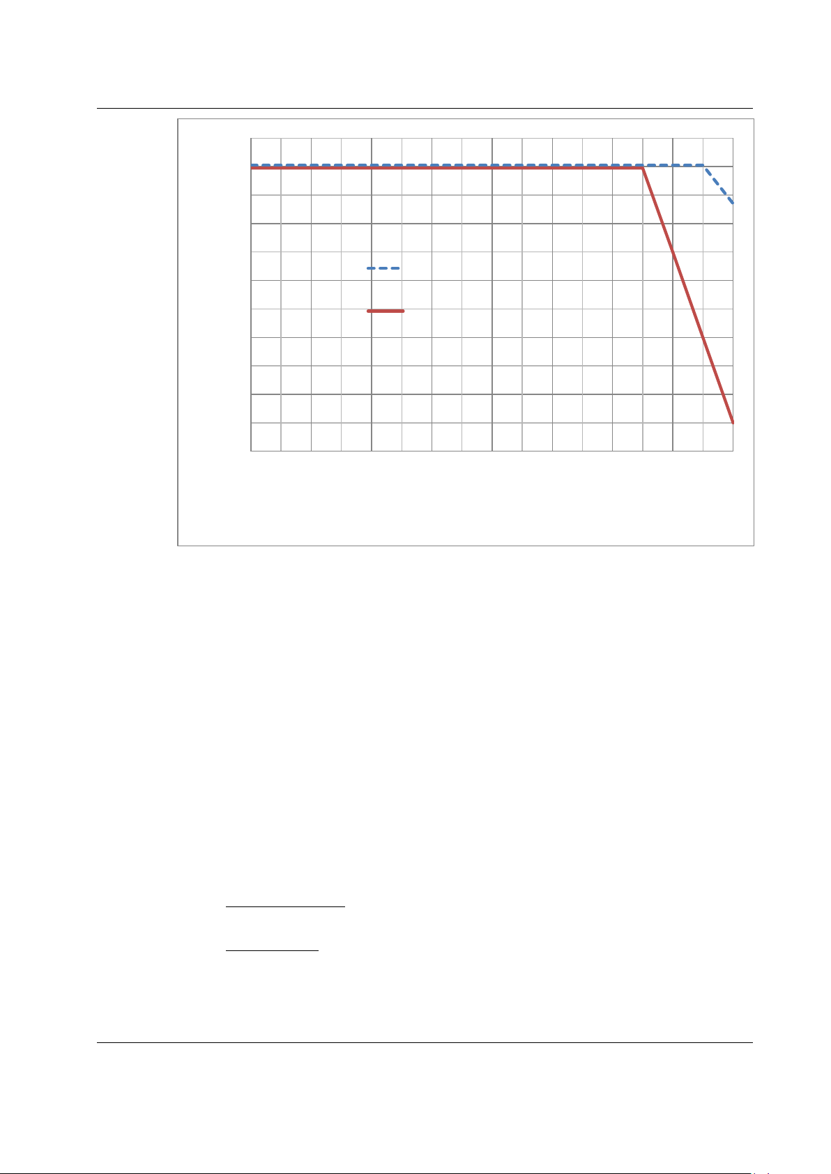
Pv [%]
T
env
[°C] environmental temperature in °C
100
80
Installation and Commissioning
60
40
20
0
-25 -15 -5 5 15 25 35 45 55
Pv [%] Power dissipation of internal Scalibur supply in %
Fig. 3.2.2.3: Derating diagram of maximum internal power dissipation
horizontal mounting
other mounting positions
T
env
[°C]
Please refer to the manuals of the Inline terminals to find out the load of the logic
supply.
Maximum load on the logic supply (2 A) and on USB (2 x 500 mA) leads to a 100%
power dissipation of 2.7 W:
P
= 1.0 V × IL + 0.7 V × I
V
P
= 1.0 V × 2.0 A + 0.7 V × 1.0 A = 2.7 W
V
USB
This power dissipation can be maintained up to a maximum environmental
temperature of 40 °C (104 °F). For higher temperatures, the load (P
PERI
and P
USB
must be reduced according to Fig. 3.2.2.3.
)
Example 1: Horizontal mounting position
For an environmental temperature of 55 °C (131 °F) and horizontal mounting, the
power dissipation is limited to 87 %, which means 2.35 W. Supposed I
loaded with the max. allowed 2 A, then the USB ports can support a maximum of
0,5 A:
I
USB
0.87 P
=
– 1 V × I
V
0.7 V
L
2.35 W – 2 W
I
USB
=
0.7 V
= 0.5 A
Manual SCA-340 / SCA-340-L sysmik.de 19
is fully
L

Installation and Commissioning
Example 2: Other mounting positions
For an environmental temperature of 45 °C (113 °F) and non-horizontal mounting,
using additionally a USB device with 200 mA, the power dissipation is limited to
70 %, i.e. 1.89 W. Therfore, the max. current from U
0.7 P
I
=
L
– 0.7 V × I
V
1.89 W – 0.14
I
=
L
1 V
1 V
USB
W
= 1.75 A
is:
L
3.2.2.5 Protective Devices of 24 V Main and Segment Supply U
Surge / overvoltage: Input protective diodes (can be destroyed by permanent
overload).
Polarity reversal: Parallel diodes. In case of wrong polarity a high current is flowing
which is blowing the external fuses.
Segment supply and main supply are related to the same ground potential.
Note: Each 24 V voltage supply must be fused externally. The power supply unit must be
capable of supplying a current four times the nominal value of the external fuse to reliably
blow the fuses in case of an error.
3.2.3 RS-485 and LON
The interface connector provides terminals for both RS-485 interfaces and (for
SCA-340-L only) the LON TP/FT-10 interface.
and US
M
Fig. 3.2.3.1: RS-485/LON Interface terminal connections
20 sysmik.de Manual SCA-340 / SCA-340-L

Installation and Commissioning
Terminalpoint
1.1
COM1 +
COM1 RS-485 data signal + positive
1.2
COM1 -
COM1 RS-485 data signal - negative
1.3
SH1
COM1 shield
2.1
COM2 +
COM2 RS-485 data signal + positive
2.2
COM2 -
COM2 RS-485 data signal - negative
2.3
SH2
COM2 shield
1.4
NT1
2.4
NT2
Name Function
LON TP/FT-10 (SCA-340-L only), polarity independent
Fig. 3.2.3.2: Terminal assignment of interface connector
For RS-485 the proper polarity has to be observed, and bias and termination
resistors have to be chosen properly. Scalibur has fitting built-in-resistors, which can
be used via DIP switches. The shield connections are internally capacitive
connected to FE (functional earth).
The connection is pluggable and includes two terminal points connected inside the
plug for each bus line. Thus the TP/FT-10 bus can be wired in one line without
additional terminals and the ICS can be removed without bus interruption.
While connecting L
ONWORKS technology based devices to the bus, the LONMARK
wiring guidelines [3] must be observed. According to the network topology one or
two network terminators such as SysMik ACC-BT have to be attached. If shielded
cables are used, the shield can be connected to the SH connector in order to avoid
electrostatic charging. The data bus is polarity independent. More detailed
information can be found in the manual of the used transceiver [2].
3.2.4 Ethernet
The Scalibur provides four Ethernet ports with built-in switch and the following
properties:
shielded RJ45 connectors
10/100BaseT, automatic detection
automatic MDI/MDI-X crossover detection
Figure 3.2.4.1: Terminal assignment of Ethernet port
Manual SCA-340 / SCA-340-L sysmik.de 21

Installation and Commissioning
The 10/100BaseT-Ports are able to recognize and to correct an interchanged
receive path pair (RD+/RD-). Thus either crossover or patch cable can be used, no
matter if the remote station is another end device, a switch or a hub.
Note: The maximum distance of 100 m between Ethernet devices can only be achieved
using cables from category 5 on.
3.2.5 USB-OTG for local Access
The local access is a connection between Scalibur and a PC, which works
regardless of the device settings (especially IP address). Simply connect a Windows
PC to the Scalibur with a standard Mini USB cable.
Installation of PC driver
With Scalibur Operating System 1.01.0 or newer, the PC driver software is
automatically installed (Windows 8.1, Windows 10).
For older Scalibur Operating Systems or when using Windows 7, the proper driver
has to be selected manually as follows:
If you connect the Scalibur to your PC for the first time, Windows detects a new
device and shows this in the Device Manager as “RNDIS/Ethernet Gadget” below
“Other devices”.
select “Update driver software…” in the local menu of the device entry
chose “Browse my computer for driver software”
chose “Let me pick from a list of device drivers on my computer”
select “Network adapters” as device type
select “Microsoft Corporation” as manufacturer and “Remote NDIS
Compatible Device” as network adapter and click “Next”
pass warning “Update driver warning” with “Yes”
close the notification window after successful device driver installation
1
1
If the device is detected as a serial COM device instead, we recommend a firmware
upgrade of the Scalibur. If that is not feasible, please contact SysMik for an alternative
solution of the driver installation.
22 sysmik.de Manual SCA-340 / SCA-340-L
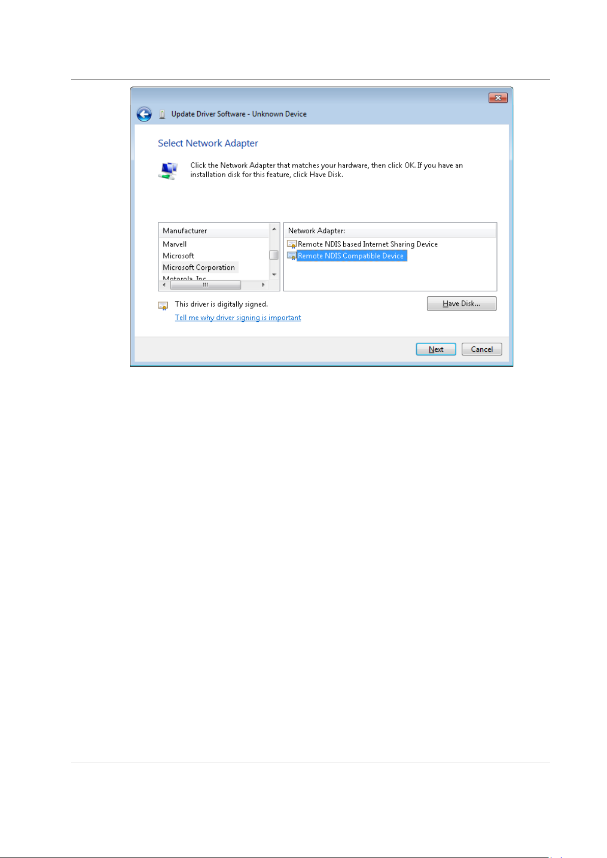
Fig. 3.2.5.1: Selecting device driver
Installation and Commissioning
The Scalibur is now located under „Network adapter“ as „RNDIS/Ethernet Gadget“.
This acts as additional network interface, which provides a local network access to
the Scalibur.
3.2.6 USB
The USB type A socket accepts USB end devices according to the standard
USB 1.0 and USB 2.0. Beside this, the device must also be supported by software
(esp. driver).
Manual SCA-340 / SCA-340-L sysmik.de 23
Installation and Commissioning
3.3 Operating Elements
3.3.1 Overview
Fig. 3.3.1.1: Front view with display and operating element s
3.3.2 Inline Supply LEDs “US”, “UM”, “UL”
LED State Description
US
UM
UL
Table 3.3.2.1: Inline supply LEDs
green voltage at segment circuit (+24 V DC)
off no voltage at segment circuit
green voltage at main circuit (+24 V DC)
off no voltage at main circuit
green U
off UBK, UL not OK
(24 V supply), UL (logic supply) OK
BK
3.3.3 Process Status LEDs “PL”, “ST”, “SE”
LED Description
PL status of Niagara Platform
ST status of Niagara station
SE status of Sedona Virtual Machine, incl. IO-server
Table 3.3.3.1: Process status LEDs
In normal operation, all three LEDs are using the same signalizing method.
24 sysmik.de Manual SCA-340 / SCA-340-L
Installation and Commissioning
The process is running and needs less than
10 % of processor time.
The process is running and needs between 10 %
and 50 % processor time.
The process is running and needs more than
50 % processor time.
Communication with the Inline Terminals is not working. Possibly, there are no
terminals attached or the terminals are not snapped-in properly.
LED status Description
off The process has not been started.
10 % on time
blinking yellow
(2 s period)
Table 3.3.3.2: Process status LED behavior
50 % on time
90 % on time
During a software update, the process status LEDs signalize the programming
process as a running light.
3.3.4 IO Status LED “IO”
The communication state of the IO terminals is signalized by a dual colored “IO”
LED, located at the supply connector.
State Description
off The IO server is not running.
green Communication with Inline terminals is OK.
red
Table 3.3.4.1: IO status LED
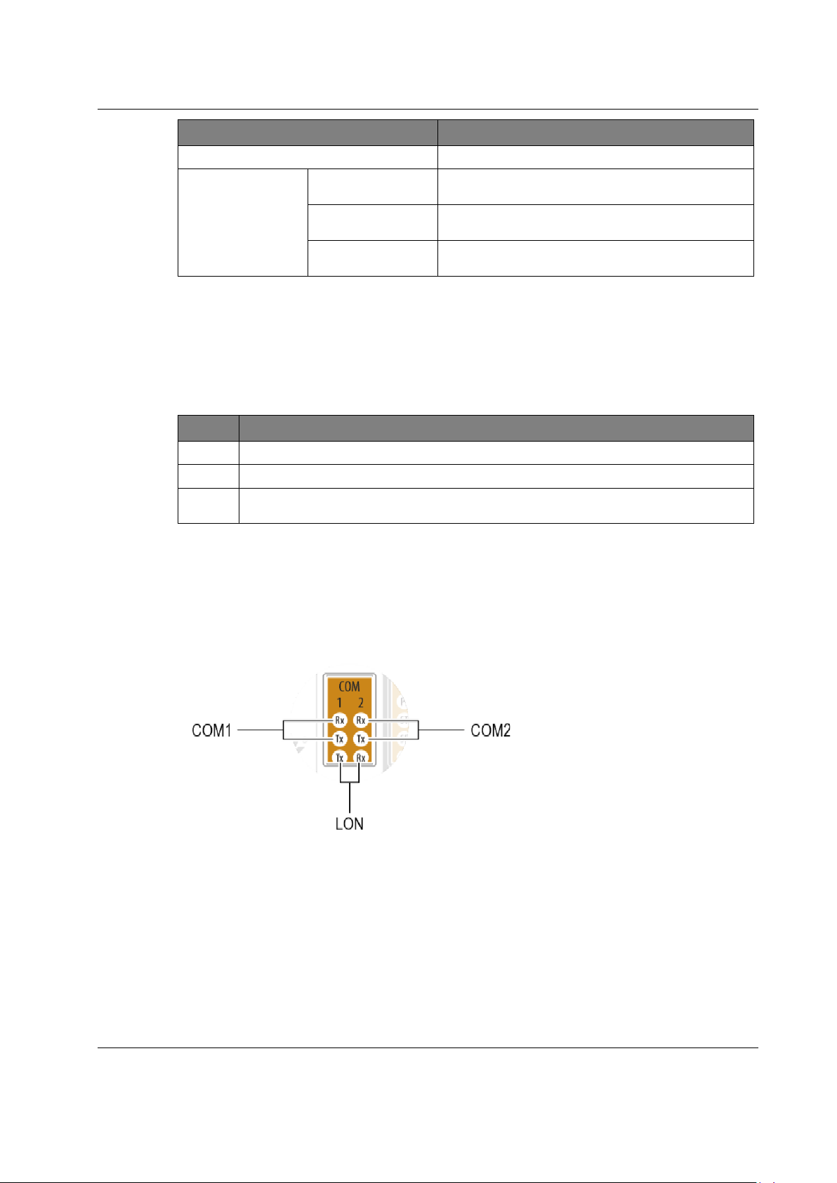
3.3.5 Communication LEDs “COM1”, “COM2”, “LON”
Located at the interface connector, the Scalibur has LEDs which signalize the data
transmission of their respective interface. The layout of the LEDs resembles the
layout of the terminals: COM1 upper left, COM2 upper right, and LON below (only
SCA-340-L).
Fig. 3.3.5.1: COM LEDs
Manual SCA-340 / SCA-340-L sysmik.de 25

Installation and Commissioning
LED state
Description
Time slice of about 2 s after booting; allows manual reset of IP
address and Niagara Platform access credentials to state of delivery.
Time slice of about 2 s after red blinking; allows manual reset of
Sedona application and kits to state of delivery.
LED State Description
COM1 Rx green Data are being received via COM1.
COM1 Tx yellow Data are being sent via COM1.
COM2 Rx green Data are being received via COM2.
COM2 Tx yellow Data are being sent via COM2.
LON Rx green Data are being received via LON (only SCA-340-L).
LON Tx yellow Data are being sent via LON (only SCA-340-L).
Table 3.3.5.1: Inline supply LEDs
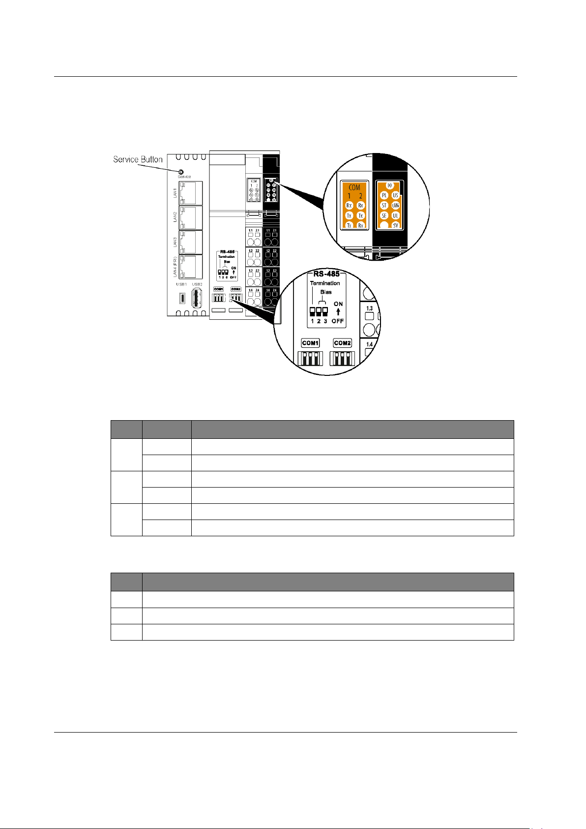
3.3.6 Service Button and LED “SV”
off normal operation and for about 7 s after power-on
red booting, approx. 7 s
blinking red 5 Hz
blinking green 5 Hz
Table 3.3.6.1: Service LED
How to reset IP address, access credentials, and Sedona
The Service button can be used in interaction with the Service LED to manually
reset IP address, Niagara Platform access credentials, Daemon HTTP Port,
Daemon HTTPS Port, and Sedona to the state of delivery.
If the Service button is pressed when the Service LED is blinking red, and is held
pressed for at least 3 s, the IP address of eth0 and the Niagara Platform credentials
are reset to the state of delivery.
If the Service button is pressed when the Service LED is blinking green, and is held
pressed for at least 3 s, the Sedona app and Sedona kits are reset to the state of
delivery.
3.3.7 Ethernet Status LEDs
Each Ethernet port has two LEDs to signalize its link and communication state.
Fig. 3.3.7.1: Ethernet status LEDs
26 sysmik.de Manual SCA-340 / SCA-340-L

LED State Description
Installation and Commissioning
Speed
Link
Table 3.3.7.1: Ethernet port LEDs
yellow 100 Mbps
off 10 Mbps (if link is active)
green electrical connection to network
short off packet transmission
permanent off no electrical connection to network
3.3.8 RS-485 Termination
RS-485 networks are using bus topology and are terminated at both ends with a
termination resistor. Additionally, the data lines are pulled once with bias resistors to
a defined idle state. The Scalibur has built-in resistors for termination (120 Ω) and
biasing (510 Ω) of COM1 and COM2, according to the BACnet MS/TP specification.
Each resistor can be separately activated via DIP switches.
Fig. 3.3.8.1: Assignment of DIP switches to RS-485 termination
Manual SCA-340 / SCA-340-L sysmik.de 27

Software
4. Software
Note: Scalibur factory defaults
Ethernet eth0 – LAN3 / LAN4: 192.168.1.1 / subnet mask 255.255.255.0
eth1 – LAN1 / LAN2: disabled
Platform-Credentials: sysmik / intesa
Sedona-Credentials: admin / no password (after Sedona activation)
Fig. 9.1: Login
4.1 Configuration Tools
Fundamental device settings are vital to the device operation and should be
protected carefully. To prevent unwanted accesses from the network while offering a
stable configuration access, which is independent of the current IP settings, the
Scalibur offers a local access via USB-OTG (see chapter 3.2.5).
The connected PC is getting another virtual network adapter, which is connected to
the Scalibur and is automatically receiving IP settings from the Scalibur DHCP
server. The IP address of the Scalibur is 172.16.0.10 in this virtual network.
28 sysmik.de Manual SCA-340 / SCA-340-L

The local access offers several services and protocols to the PC for configuration
and diagnosis.
Protocol Port PC-Software Application
Telnet 23 Telnet client SCA system shell
HTTP 8080 Web browser commissioning website
Table 4.1.1: Protocols of local access
4.1.1 SCA System Shell
The SCA System Shell allows to configure fundamental settings of the Scalibur. To
this end, the PC is connected via USB-OTG to the Scalibur and then a Telnet client
is used on the PC to establish a Telnet session with the Scalibur (address
172.16.0.10 / port 23).
The SCA System Shell shows host ID, version information of several software
components, the current time, and the IP addresses of the Scalibur. A numberbased menu allows to perform different actions:
1. Update System Time configure current system time
2. Update IPv4 Settings configure IP addresses
3. Update IPv6 Settings configure IPv6 addresses
4. Switch Configuration configure the Ethernet switch (Ethernet
5. Ping IPv4 Host ping an IP address from the Scalibur
6. SSH/SFTP usage start/stop SSH/SFTP server
7. Sedona/Niagara Enable activate/deactivate Niagara and Sedona
8. IO Server configure IO server (port number,
9. Sedona Factory Default reset Sedona app and Sedona kits to
10. Reset Platform Credentials reset Platform credentials to default
11. Reboot reboot Scalibur
x. Exit exit Telnet session
Software
port assignment to IP interface, RSTP,
ring monitoring, broadcast storm
protection)
remote address)
state of delivery
(user sysmik / password intesa /
Daemon HTTP Port 3011 / Daemon
HTTPS Port 5011)
4.1.2 Commissioning Website
The commissioning website allows to configure the Scalibur and to access data
points of connected IO terminals.
To this end, a PC is connected via USB-OTG to the Scalibur and the following URL
is entered in the address field of the web browser:
172.16.0.10:8080
Manual SCA-340 / SCA-340-L sysmik.de 29

Software
The page Overview shows host ID and version information of several software
components.
Page Settings allows to configure several settings:
Network to configure IP addresses
Webserver to configure the port at which the restricted webserver (without
device settings) is accessible
Date/Time to configure current time and time zone
IO Server to configure the IO server (port number, remote access)
Run to activate/deactivate Niagara and Sedona
Switch to configure the Ethernet switch (Ethernet port assignment, RSTP,
ring monitoring, broadcast storm protection)
On the page Terminals, the data points of the connected IO terminals can be
observed and manually overridden (see 4.2.3).
The webserver hosts further web pages, which are alternatively also available via
Ethernet:
DALI configurator to assign addresses to DALI ballasts (connected via
DALI terminals) and configure them
User defined visualization pages, which are created using Sedona
programming [4].
4.1.3 File Access via FTP
The Scalibur has an SFTP server to access the file system. This can be used to
load software updates from the PC to the Scalibur. The SFTP server can only be
activated and deactivated from the SCA System Shell (see chapter 4.1.1). A
password for the user “sftpuser” can be defined.
In parallel to SFTP an SSH server can be activated. It can be used for command
line based diagnosis of the controller by the manufacturer only.
4.2 Commissioning Scalibur
Scalibur comes with a default configuration and settings like IP addresses, time,
time zone, and others have to be specifically configured.
The following Scalibur functions are active:
The SCA System Shell expects input.
The IO server detects the connected IO terminals and opens its interface
for commissioning website, Sedona, and Niagara.
The commissioning webserver hosts the commissioning website.
The Niagara daemon is ready for a Platform connection with Workbench
(user sysmik / password intesa). Though there is no station running – these
can be loaded later during the Niagara commissioning.
Changing IP addresses or time zone becomes effective only after reboot.
30 sysmik.de Manual SCA-340 / SCA-340-L

4.2.1 IP Addressing
Scalibur’s default IP address of the primary IP interface (eth0) is 192.168.1.1, the
subnet mask 255.255.255.0. The secondary IP interface (eth1) is deactivated by
default. There are several ways to configure the IP settings:
SCA System Shell (see 4.1.1)
Commissioning website via Settings/Network (see 4.1.2)
Workbench via Platform connection with the Niagara daemon under TCP/IP
Configuration
4.2.2 Time and Time Zone
The internal time is derived from a buffered RTC. At delivery the buffer capacitor is
usually discharged and the time at the first start of the Scalibur is set to midnight
2000-01-01. Time and time zone (default Central European Time CET or Central
European Summer Time CEST) can be configured in several ways:
SCA System Shell (see 4.1.1)
Commissioning website via Settings
Workbench via Platform connection with the Niagara daemon under
Platform Administration
4.2.3 Hardware Data Point Test
Usually, the electrical connection and the software integration of control stations are
done by different persons and at different times. Ideally, the electrical installation
(mounting and cabling) should be finished with a data point test and its according
documentation. This is supported by the commissioning webserver, which clearly
visualizes all input and output signals of the IO terminals. If required, output
channels and also their configuration, like measuring ranges, can be manually
overridden. Thus, a data point test doesn’t need any application software. By leaving
the commissioning page (either manually or by timeout), all overrides are reverted.
Date/Time (see 4.1.2)
Change Date/Time
Software
Manual SCA-340 / SCA-340-L sysmik.de 31

Software
Table 4.2.1: Testing data points via commissioning webpage
32 sysmik.de Manual SCA-340 / SCA-340-L

4.3 Ethernet Switch for Flexible Network Topologies
LAN1
LAN2
LAN3
LAN4
LAN1
eth1
LAN2
LAN3
LAN4
The integrated Ethernet switch with four external and two internal ports, allows
Ethernet cabling without additional switches. It supports:
free assignment of IP interfaces to external Ethernet ports
ring monitoring with automatic port deactivation
Rapid Spanning Tree Protocol (RSTP) to manage redundant Ethernet
topologies
throtteling of Ethernet traffic to prevent multicast and broadcast storms
The Ethernet switch can be configured here:
SCA System Shell (see 4.1.1)
Commissioning Website (see 4.1.2)
WorkPlace via Fox connection with Niagara Station under
Config
(SysmikScaSwitchCfgView)
When using ring monitoring or RSTP, the status of the respective ports (activated,
deactivated) is changed automatically. The port status information shows the state
of the redundant topology. The state of the external Ethernet ports is provided in the
Niagara Station, in the Sedona Application, and on the Commissioning Website.
Factory default:
RSTP deactivated
ring monitoring deactivated
Broadcast/Multicast throtteling: 1Mbps
eth1on ports LAN1, LAN2
eth0 on ports LAN3, LAN4
DriversSysmikScaIoNetworkLocalPlatformEthSwitch
Software
4.3.1 Assignment of IP Interfaces to External Ethernet Ports
The Ethernet Switch connects the two internal IP interfaces eth0 and eth1 with the
external Ethernet ports. Fig. 4.3.1.1 to Fig. 4.3.1.4 show the possible combinations.
eth0
Fig. 4.3.1.1: LAN1-4 on eth0, eth1 deactivated
eth0
Fig. 4.3.1.2: LAN2/3/4 on eth0, LAN1 on eth1
Manual SCA-340 / SCA-340-L sysmik.de 33

Software
LAN1
LAN2
LAN3
LAN4
LAN1
LAN2
LAN3
LAN4
eth0
eth1
eth0
Fig. 4.3.1.3: LAN3/4 on eth0, LAN1/2 on eth1 (factory default)
eth1
Fig. 4.3.1.4: LAN4 on eth0, LAN1/2/3 on eth1
If an IP interface has more than one Ethernet port assigned to it, the IP interface is
accessible on each of these ports. Also, Ethernet traffic is forwarded between these
ports, so that several devices can be linked in a line-topology (see Fig. 4.3.1.5).
Between Ethernet ports that do belong to different IP interfaces there is no Ethernet
traffic (i.e. these ports are completely separated at Ethernet level).
Fig. 4.3.1.5: Example of Ethernet wiring
34 sysmik.de Manual SCA-340 / SCA-340-L
4.3.2 Ethernet Ring Monitoring
eth
LAN
RSTP configurations
1
A)
2
A)
3
B)
4
B)
eth
LAN
RSTP configurations
1 1 0 2
3
4
Ethernet ports LAN3 and LAN4 allow to build an Ethernet ring, provided both ports
belong to eth0. The Ethernet ring connects Ethernet field devices with integrated
unmanaged switch (with at least two Ethernet ports, like SysMik's SCC devices) and
ensures Ethernet communication even when one connection in the ring is broken
(see Fig. 4.3.1.5).
If the ring is completely closed and the involved switches are unmanaged ones, a so
called broadcast storm is likely to occur: because broadcast and multicast
messages are always forwarded, they circulate in the ring and create high traffic
load. The Ethernet ring monitoring observes always the state of the ring and
deactivates LAN4 when the ring is faultless. If the ring connection is broken at one
point, LAN4 is activated.
Note: The time for complete recovery of the communication in the ring is defined by the
aging-time of the switches in the ring.
4.3.3 Rapid-Spanning-Tree-Protocol (RSTP)
The Rapid-Spanning-Tree-Protocol allows to build arbitrary redundant Ethernet
structures, also beyond simple ring structures, by detecting redundant paths in the
system and disabling them as long as they are not needed. As soon as a connection
is broken it will be replaced by a redundant path (provided there is one). RSTP
needs just a few seconds to re-establish a broken connection.
Software
Note: Inside an RSTP structure, all involved Ethernet switches must support RSTP and must
be adequately configured.
Tables 4.3.3.1 to Table 4.3.3.4 show the possible combinations regarding RSTP. A
LAN port can be configured for RSTP if there is at least one further LAN port
assigned to the same IP interface.
0
A), B)
RSTP topologies independent of each other
Table 4.3.3.1: LAN1-4 at eth0, eth1 deactivated
Table 4.3.3.2: LAN2/3/4 at eth0, LAN1 at eth1
Manual SCA-340 / SCA-340-L sysmik.de 35

Software
eth
LAN
RSTP configurations
1
2
3
4
eth
LAN
RSTP configurations
1
2
3
0 4
1
0
Table 4.3.3.3: LAN3/4 at eth0, LAN1/2 at eth1 (factory default)
1
Table 4.3.3.4: LAN4 at eth0, LAN1/2/3 at eth1
4.3.4 Port Status Informations
If ring monitoring or RSTP is active, then the state of the external Ethernet ports is
available in the Niagra station, the Sedona application, and the Commissioning
Website. This allows to check whether the redundancy of a topology is still intact.
When a path gets disconnected, formerly inactive ports will be activated, which can
be signalized.
Sedona PlatformService Lan1State…Lan4State: Boolean
true = FORWARDING
false = BLOCKING
null = no current information available (RSTP or loop not active)
Niagara Station Config
Lan1State…Lan4State: Status Boolean
true {ok} = FORWARDING
false {ok} = BLOCKING
xxx {stale}: no current information available (RSTP or loop not active)
xxx {disabled}: status check disabled (configurable via
Config
DriversSysmikScaIoNetworkLocalPlatformEthSwitch.Enabled)
DriversSysmikScaIoNetworkLocalPlatformEthSwitch
4.3.5 Broadcast Storm Protection
36 sysmik.de Manual SCA-340 / SCA-340-L
Broadcast storm protection limits the traffic rate for multicast and broadcast packets.
Configurable values are 0.032 / 0.05 / 0.1 / 0.5 / 1 (factory default) / 2 / 5 / 10 / 20
Mbps. This setting applies to all four ports.
Even with ring monitoring and RSTP, redundant paths can't be completely avoided.
From detecting a topology change it takes several seconds until the reorganization
is completed. In this period a broadcast storm can develop, which might interfere
with the management messages for the reorganization, thus effectively preventing a
proper reorganization. The broadcast storm protection function limits the traffic load
of broadcast and multicast messages and terminates broadcast storms.
4.4 Real-Time Control with Scalibur and Sedona
Sedona allows to program control applications, which run with configurable cycle
times. Sedona must first be activated from the SCA system shell (s. 4.1.1) or the
commissioning website (s. 4.1.2). Niagara Workbench is used as engineering tool.
The programming follows a component-based approach: The application consists of
components, which are parameterized and connected with each other. With the
textual programming language Sedona (similar to C++ and Java), it is even possible
to create own Sedona components. An introduction to Sedona offers [4], while
further, more detailed information can be found in [6].
4.4.1 IO Access
Hardware data points can be accessed via the terminal components of the
SysMikScaIo kit. There is a component for each terminal type with its specific slots,
that allow to access inputs and outputs and to parameterize the terminal.
The component ScaIo works as folder, into which the hardware related components
are added. Furthermore, it provides an Action Restart IO to restart the IO server.
Each terminal component has a property Terminal, which defines the terminal
position. The first terminal directly at the Scalibur has position 1, and so on. Some
terminal components contain further parameters (e.g. measuring ranges for analog
input terminals) or actions (e.g. counter initialization of pulse metering terminals).
Software
Table 4.4.1: PropertySheet view of a terminal component
4.4.2 Modbus
Via Platform Service, a Modbus TCP server can be started for the Sedona Virtual
Machine, which hosts the following data points:
10,000 coils (digital outputs)
10,000 discrete inputs (digital inputs)
10,000 holding registers (analog outputs)
10,000 input registers (analog inputs)
The Sedona application has access to these data points via components of the kit
SysMikModbusServer.
Additionally, with components of the kit SysMikModbusClient, the Sedona
application can act as Modbus TCP client or Modbus RTU master to read and write
data points of remote Modbus devices.
Manual SCA-340 / SCA-340-L sysmik.de 37

Software
4.4.3 Platform Service
The platform service (SedonaAppserviceplat) is a mandatory element of any
Sedona application and allows device specific configurations:
Timezone – time zone, e.g. Europe/Berlin
IP-Addressing
- Ip Addressing – static or DHCP
- Ip Address
- Ip Net Mask – subnet mask
- Ip Gateway – gateway address
- Ip Dns1, Ip Dns2, Ip Dns3 – Domain Name Server
Sntp Address – SNTP server address
Modbus TCP server
- Modbus Port (0 to deactivate Modbus server)
- Unit-ID
Modbus RTU
- Modbus Rtu Enabled
- Modbus Rtu Baud
- Modbus Rtu Parity
- Modbus Rtu Stop Bits
Niagara enabled – in case the parallel operation of Niagara and Sedona is
not wanted, Niagara can be deactivated or again be enabled
IoPort – TCP port number of the IO server
IoRemoteAddr – to prevent an unwanted remote control of Scalibur IOs by
other Niagara stations, a remote control address can be configured. Default
is empty which blocks remote control completely. It is possible to allow
remote control only for a specific IP address by setting the entry to this
specific IP address. 255.255.255.255 allows remote control from any IP
address..
All configurations require a restart of the Scalibur to become effective.
38 sysmik.de Manual SCA-340 / SCA-340-L

4.5 Integration with Scalibur and Niagara Framework
The Niagara framework contains many communication protocols, which are
automatically available in the Scalibur, too:
BACnet IP, BACnet MS/TP (only at COM1 and COM2), LonWorks IP852, LonMark
TP/FT-10 (only SCA-340-L), Modbus TCP, Modbus RTU, M-Bus, KNX/IP, SNMP,
oBIX, Sedona and many more. Data points from different sources can be integrated
and connected using these communication protocols. Niagara offers a rich set of
processing and system functions, like trend log, alarming, scheduling, web
visualization, report generators, and interfaces to e-mail, SMS, data bases and
other. All the engineering is done with a single tool – Workbench.
4.5.1 Local IO Access
The components of the module sysmikScaIo allow to access the IO terminals. This
follows consequently the approach of the Niagara Driver Framework (Network –
Device – Point): SysMikScaNetwork – Terminals – Data points (IO channel).
From the Driver Manager, the default view of Station
SysmikScaIoNetwork is created via New.
In the N Device Manager, the default view of the SysmikScaIoNetwork, the
connected terminals can be detected via Discover. The detected terminals can be
inserted to the station via Add.
ConfigDrivers, a
Software
Fig. 4.5.1.1: N Device Manager of the SysmikScaIoNetwork
Manual SCA-340 / SCA-340-L sysmik.de 39
Software
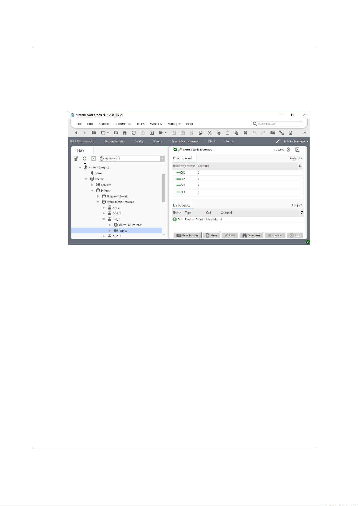
In the N Point Manager, the default view of the points folder, the available IO
channels can be displayed via Discover. These can be inserted as proxy points to
the station via Add. Some data points have specific functions:
Measurement ranges of the analog input terminals can be configured with
the additional property Ai Type of the proxy extension.
Counter values of the pulse metering terminal can be initialized with the
action Init Counter of the proxy extensions.
Fig. 4.5.1.2: N Point Manager of a terminal component
40 sysmik.de Manual SCA-340 / SCA-340-L

4.5.2 Serial Interfaces
The Scalibur has two serial RS-485 interfaces, that are available as COM1 and
COM2 for any serial protocols. All relevant baud rates equal or above 200 baud are
supported.
Further serial interfaces can be added via IO terminals. Universal serial terminals of
type IB IL RS UNI support the interface types RS-232, RS-485, and RS-422, which
can be configured with Workbench via their associated terminal component in
SysmikScaNetwork. IB IL RS 232-ECO and IB IL RS 485-ECO support serial
interfaces types regarding their names. The serial interfaces of the IO terminals can
be used as master for serial protocols except BACnet MS/TP. The supported baud
rates are documented in the data sheets of the terminals.
Terminals of type IB IL MBUS extend the Scalibur by serial interfaces according to
the M-Bus standard for connection of up to 30 M-Bus slaves and are controlled with
the Niagara M-Bus driver.
The interface names of the serial terminals are assigned according to their position,
starting with COM3.
A summary of all serial interfaces, including their current use (owner) is available at
Station/Config/Services/PlatformServices/SerialPortPlatformServiceNpsdk.
Example:
The screenshot shows an overview for a Scalibur controller with 4 serial ports total –
two from the controller itself and two added via serial terminals:
COM1: The first built-in RS-485 interface is used by the MS/TP port of the
BacnetNetwork.
COM2: The second built-in RS-485 interface is assigned to the
ModbusSlaveNetwork.
COM3: The IB IL MBUS terminal at Inline position 7 is used as interface for
the MbusNetwork.
COM4: The IB IL RS UNI terminal at Inline position is used by the
ModbusAsyncNetwork. To this end the property RsType of the terminals
PropertySheet in SysmikScaNetwork is set to RS-485.
Software
Manual SCA-340 / SCA-340-L sysmik.de 41

Software
Fig. 4.5.2.1: SerialPortPlatformServiceNpsdk
Fig. 4.5.2.2: Interface configuration of IB IL RS UNI
42 sysmik.de Manual SCA-340 / SCA-340-L

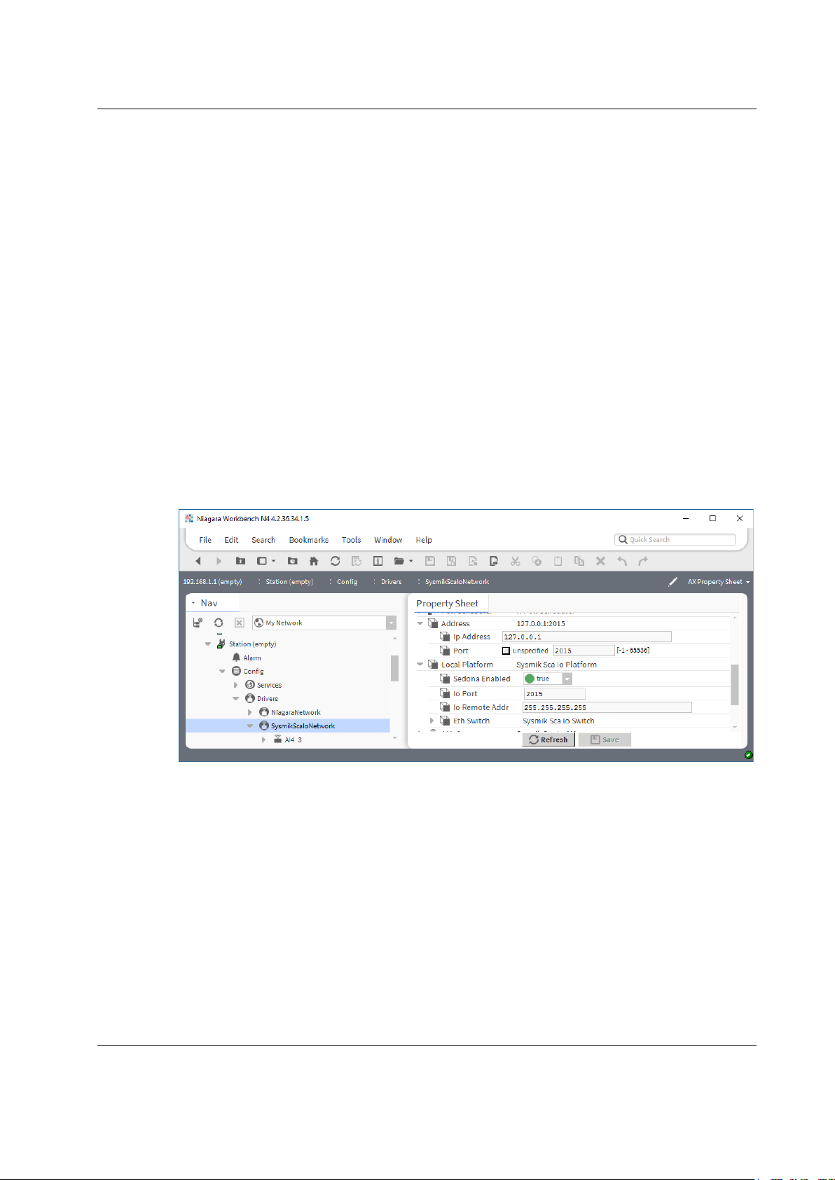
4.5.3 IO Remote Control
The SysmikScaNetwork sets up a TCP connection to an IO server, to access the IO
terminals. The property Address defines address and port of this server. Default is
the local address 127.0.0.1:2015, which establishes contact to the local IO
server. But it is also possible to connect to an IO server of a different device by
configuring its address here.
Fig. 4.5.3.1: Configuration of the IO server to be contacted
To do so the remote access must be activated first. In Workbench an allowed
remote control address can be configured via
Station
ConfigDriversSysmikScaIoNetworklocalPlatformIoRemoteAddr
Software
Address setting Description
invalid address (empty string) remote control deactivated (default)
valid IP address IO server accepts only accesses from this IP address
255.255.255.255 any IP address can access the IO server
Table 4.5.3.1: Address settings for IO server access
Furthermore, the port number of the IO server can be defined via
Station
Fig. 4.5.3.2: Configuration of IO server
ConfigDriversSysmikScaIoNetworklocalPlatformIo Port
4.5.4 Sedona Integration
Data points of the local Sedona application can be added to Niagara via the Sedona
driver. If a parallel operation of Niagara and Sedona is not desired, Sedona can be
deactivated via
Station
ConfigDriversSysmikScaIoNetworklocalPlatformSedonaEnabled
Manual SCA-340 / SCA-340-L sysmik.de 43

Software
Analog output,
DALI-control, float
4.6 Concurrent Access to the IO Terminals
Several software components can access the IO terminals of the Inline system. For
reading input data, this poses no problems. For outputs and configuration however,
the different program parts could work against each other. In order to achieve a
predictable behavior of the IOs, there is a channel-wise priority control.
Each source can set a value with its source-specific priority, or release its access.
This release is using technology specific values:
Type
Digital output, bool auto null null
Measuring range, enum auto auto auto
Table 4.6.1: Release values of priority control
If several sources try to access the same IO channel, the following ranking applies:
Rank Component
1 Commissioning website (i.e. manual override in test mode)
2 Sedona
3 Niagara local access
4 Niagara remote access
Table 4.6.2: Ranking of priority sources
The commissioning website has highest priority. Manual override is always possible
regardless of the other program components. By leaving the commissioning page,
all overrides are automatically released.
Sedona and Niagara components do by default release their priority. Only if they are
configured or connected to other components, the priority is actually used.
Note: Deleting or re-addressing components does not automatically release the
priority of this channel. Of course, a priority could be manually released by setting
explicitly to the release value. Restarting the Scalibur re-initializes (releases) the
complete internal priority array.
Commissioning
website
auto nan (not a number) null
Sedona Niagara
44 sysmik.de Manual SCA-340 / SCA-340-L

Software
Depending on the data point type, the following default values apply if all priorities
are released (that is, no software component accesses this channel):
Type of data point Default value
Digital output – output signal off
Analog output – output signal 0.0 V
DALI control - ballast 0.0 %
Analog input – measurement range 0..10 V, if applicable
Table 4.6.3: Default values of priority control
Some actions have command character. These do not change the priority level, but
are processed in their order of occurrence (or suppressed completely in case of
insufficient priority). Such commands are:
Initialization of counter values of the pulse metering terminal
DALI lighting control commands
Initialization, read and write operations of serial terminals
For these cases it is up to the application programmer to prevent unwanted
concurrent accesses from different sources.
Manual SCA-340 / SCA-340-L sysmik.de 45

Best Practices and Troubleshooting
5. Best Practices and Troubleshooting
5.1 Performance and Resource Management
All software processes share the common resources (processor time, memory).
Besides the complexity of the application itself, the interface definitions, especially
the connected I/O terminals have an important impact on ressource usage. While
each data point needs ressources just by its existence, it is usually also processed
within the application, thus enlarging the application.
Note: All quantitative information given in this chapter are not guaranteed. They may help
you to estimate the load caused by I/O terminals.
I/O terminals
Scalibur can handle up to 63 I/O and function terminals. This is a rather theoretical
limit, which gets relativated by the geometrical size of the station. In general,
stations with more terminals need more time to transfer data between controller and
terminals. Digital input and putput terminals have the least performance impact.
If you connect 63 digital I/O terminals with 32 channels each, the station has 2016
I/O datapoints, while being more than 9 ft. wide. Supply and segment terminals
might enlarge the stations width even further.
IB IL DALI/PWR, IB IL DALI, IB IL DALI/MM
A DALI terminal can adress up to 81 data points (64 short addresses, 16 group
addresses, one broadcast). The ressource demand depends on the number of DALI
ballasts and how they are controlled:
addressing via broadcast (one data point, no status), maybe using scenes
group addressing (some data points, which are written on change only, no
status)
individual addressing (many data points, which are written on change only)
individual addressing with evaluation of ballast status (many data points,
which are polled periodically)
individual or group addressing with additional use of DALI sensors
While e.g. broadcast addressing needs little ressources and would allow the
maximum number of 63 DALI terminals, for a higher load on the DALI terminals no
more than 8 DALI terminals should be used. Especially when using DALI sensors,
the desired reaction time is an important criterion.
IB IL RS UNI, IB IL MBUS, IB IL RS 232-ECO, IB IL RS 485-ECO
These terminals are serial interfaces which can have 30 (MBus) or more slave
devices. The limiting factor is here the required poll rate or reaction time. The hard
limit is 16 serial terminals, but then no other terminals could be added. We
recommend to use 8 terminals at the most.
With Modbus RTU, the max. number of about 4-5 messages per second can be
achieved with one connected terminal IL IL RS UNI. When 8 such terminals are
connected, the poll rate drops to about 2 messages per second (for each terminal).
46 sysmik.de Manual SCA-340 / SCA-340-L

Diagnosis
The available resources can be shown in Workbench using all accesses:
Platform: Platform Administration
Station: Views
Sedona: App
Note: The system load should be below 100 %, because otherwise the relevant timing (cycle
times) can’t be ensured. Optimize in this case your application, i.e. by increasing Sedona
task cycle time or intervals of the Niagara station (e.g. poll intervals). Please be aware that
every kind of communication creates processor load, too – so leave a margin for that.
Resource Manager
serviceplat (see [4])
5.2 Reliability of Nonvolatile Memory
Scalibur contains a highly integrated Flash memory for use in the industrial
temperature range. Physically caused, the reliability is depending on the number of
writes and the environmental temperature: frequent writing of large data blocks
wears out the memory and a high environmental temperature reduces the
guaranteed data retention time.
The stress on the memory depends heavily on the application. Occasional write
accesses due to programming and software upgrades cause writing of large data
blocks to the Flash. However, these are almost negligible in comparison to the
amount of data which is written in regular intervals, like logging of history data or
StationSave.
The write load caused by history data can be shown via
Station
Size and write frequency of history data should be configured in such a way, that
writing of a data recovery block happens less than once a minute.
StationSave should be performed much less than once per hour.
Regarding the environmental temperature, the defined maximum values in chapter
Fehler! Verweisquelle konnte nicht gefunden werden. must not be exceeded
and the mounting position has to be observed (see chapter 3.1.2).
ConfigServicesPlatformServicesDataRecoveryService.
Best Practices and Troubleshooting
5.3 Diagnosis and Troubleshooting
Scalibur is a very complex device with many functions and interfaces. This
complexity leads to many possible misconfigurations in practical use. Most mistakes
arise from connections with other devices or components. Therefore the controller
should not be diagnosed isolated, but in context with the complete system.
Several tools allow to locate possible reasons for failures:
power LEDs (see 3.3.2)
software status LEDs (see 3.3.3)
IO status LED (see 3.3.4)
communication LEDs (see 3.3.5)
diagnosis LEDs of the connected IO terminals
Service LED (see 3.3.6)
Ethernet status LEDs (see 3.3.7)
Manual SCA-340 / SCA-340-L sysmik.de 47

Best Practices and Troubleshooting
Additionally, Niagara provides powerful tools to analyze the communication in
connected automation networks.
Before starting a detailed analysis, make sure that the device is properly wired,
supplied and has finished booting. Check especially
if all IO terminals are properly interlocked and connected by their feather
keys/keyways
if the mounting rail is properly grounded
if the functional earth connector of the device is connected using a 1.5 mm²
(AWG ) wire with the mounting rail via a earthing clamp
if the LEDs UM, US, UL are permanently on
if the power supply voltage is within the allowed tolerance range
A good indicator are the tree software status LEDs (see 3.3.3). Only if they
are regularly blinking, the boot process has finished.
5.3.1 SCA System Shell / Commissioning Website is not accessible
Both of these need an USB cable from the PC USB port to the Mini USB port of the
Scalibur.
Please verify that the cable is not damaged and is properly plugged into both
sockets.
Check if the Device Manager shows the device Remote NDIS Compatible Device is
shown as Network adapter. If not, re-install the device driver (see 3.2.5).
5.3.2 IP Address unknown
The IP addresses of the Scalibur can be shown and modified via the SCA System
Shell or the commissioning website. Both accesses work independent of the current
IP settings via a local USB connection (see 4).
5.3.3 No IP Communication
The command ping allows to test the Ethernet connection between two devices. The
SCA System Shell provides a ping function.
Please check first the proper connection of the Scalibur to the Ethernet using the
Ethernet status LEDs.
Then, the IP addresses and subnet masks of all devices that shall communicate with
each other. Especially ensure unique IP addresses and proper subnet settings.
5.3.4 Unknown Niagara Platform Access Credentials
If the access credentials are lost, they can be reset to their default value (user
sysmik / password intesa) with the Service button (see 3.3.6). The Scalibur has to
be restarted and the Service button must be pressed at the right moment.
48 sysmik.de Manual SCA-340 / SCA-340-L

Best Practices and Troubleshooting
logic voltage ok, error at interface between blinking and previous terminal
(e.g. loose contact, defective terminal, hot-plugging of terminal)
5.3.5 No Platform Connection to Device - Platform Daemon is not starting
If the Platform daemon doesn’t start, it's not possible to connect to the Niagara
Platform of the device. This can be identified by looking at the PL LED (see Table
3.3.3.1): it doesn't blink or ceases to blink about one minute after the start. Possible
reasons and measures:
Daemon HTTP Port is doubly used
The Daemon HTTP Port must not be used by any other system component (e.g. by
the IO server).
Check with the SCA System Shell (see 4.1.1) or the Commissioning Website (see
4.1.2), that there is no other software component (webserver, IO server) is using the
Daemon HTTP Port (default: standard 3011 / secure 5011).
The Daemon HTTP Port can be reset to its default value using the Service button
(see 3.3.6) or the SCA System Shell.
RTC date in invalid range
If the device has no power supply for several days, eg. when in storage, the RTC
can loose its date, which is then set to a random value at start. A date outside the
range of June, 6
Platform daemon.
Set the date with the SCA System Shell to a value inside the above mentioned
range. Check the Operating System version with the SCA System Shell or the
Commisioning Website. If the version is ≤ 1.0.1.2, then the device software needs to
be upgraded. Versions from 1.0.1.3 on will automatically fix a date outside of this
range.
th
2015 to December, 29th 2020 prevents starting the Niagara
5.3.6 Sedona Virtual Machine is not Starting
Sedona must be activated from the SCA system shell (s. 4.1.1) or the
commissioning website (s. 4.1.2). If the Scalibur Sedona files (app.sab and
kits.scode) are corrupted or inconsistent, the SVM cannot start. In this case, a
device connection from Niagara Workbench to the Sedona controller is not possible.
Consequently, Sedona tools cannot be used to fix this situation.
Instead, the Service button offers a way to overwrite these files with default files
(see 3.3.6). The Scalibur has to be restarted and the Service button must be
pressed at the right moment.
5.3.7 IO Errors
Important indicators for the state of the IO terminals are Scalibur’s IO LED and the
diagnosis LEDs of the Inline terminals (labelled “D”).
State Description
off no logic voltage
on logic voltage ok, local bus active
blinking 0.5 Hz logic voltage ok, local bus not running
blinking 2 Hz logic voltage ok, peripheral error (see manual of specific terminal)
blinking 4 Hz
Table 5.3.7.1: Behavior of diagnosis LED D
Manual SCA-340 / SCA-340-L sysmik.de 49

Technical Data
Processing unit
Processor / clock
ARM® Cortex® A8 32 bit RISC processor 1 GHz
1 GB
(512 MiB for hardware version <06 – see serial label)
eMMC
1.8 GB
NVRAM
512 KiB buffered for 5 days
RTC
buffered for 5 days
Ethernet switch
Connections
4 x 10/100BaseT
MDI/MDI-X crossover
automatic
Aging time
default 330 s
Isolation
LAN1/2/3/4 vs. module
test voltage 1500 V AC, 1 min 1)
LAN vs LAN
test voltage 1500 V AC, 1 min 1)
RS-485 (COM1, COM2)
Max. number of bus devices
256 (1/8 unit load)
Max. data rate
200 kbps
Isolation
RS-485 vs. module
test voltage 500 V AC, 50 Hz, 1 min 1)
RS-485 Port 1 vs. RS-485 Port 2
test voltage 500 V AC, 50 Hz, 1 min 1)
LON TP/FT-10 (twisted pair bus connection for free topology)
Transceiver
TP/FT-10
Isolation
LON vs. module
test voltage 250 V AC, 50 Hz, 1 min 2)
6. Technical Data
DDR3 SDRAM
50 sysmik.de Manual SCA-340 / SCA-340-L
Connecting Inline automation terminals
Max. number of I/O terminals per
Inline station
Max. load of logic supply (UL)
2 A
Max. load of analog supply (U
ANA
)
0.5 A
Max. ampacity of potential routing
contacts UM, US, and GND
Isolation
none
General electrical data
Supply voltage UBK
24 V DC
Absolute limits
19.2 V to 30 V DC
Current drain at nominal voltage without local bus terminals
IBK
≤ 170 mA
Current drain at nominal voltage with local bus terminals (without UM and US)
≤ 1.5 A (7.5 V logic supply loaded with 2 A and 24 V
analog supply with 0.5 A, no USB devices)
Connections
Supply, RS-485, TP/FT-10
Type
Spring-cage terminals
Rated cross section
0.08 mm2 to 1.5 mm2, 24 - 16 AWG
Ampacity
8 A
Ethernet
Type
RJ45, shielded
Enclosure
Width x height x depth
80 mm x 119,8 mm x 71,5 mm
Weight
approx. 230 g / 8 oz
PV [%]
env
63
8 A
100
80
Derating of logic supply and USB
supply, depending on mounting
position
60
40
20
Technical Data
horizontal mounting
other mounting positions
0
-25 -15 -5 5 15 25 35 45 55
T
[°C]
IBK 2)
Manual SCA-340 / SCA-340-L sysmik.de 51

Technical Data
Environmental conditions
Operating temperature
-25 °C to 55 °C (32 °F to 122 °F)
max.
-25 °C to 85 °C (-4 °F to 158 °F)
recommended
-25 °C to 35 °C (-4 °F to 95 °F)
Rel. humidity
0 % to 75 %, non condensing
Protection standard
IP20
Immunity according EN 61000-6-2 (industrial)
IEC 61000-4-2 (ESD)
8 kV air discharge
IEC 61000-4-3 (immunity field) 10 V/m
criterion A
IEC 61000-4-4 (burst) 2.0 kV
criterion A
IEC 61000-4-5 (Surge)
LON (symmetrical/asymmetrical) 0,5 kV
criterion A
IEC 61000-4-6 (conducted immunity) 10 V/m
criterion A
Emission according EN 61000-6-3 (residential, commercial and light-industrial)
EN 55022 (conducted)
passed
EN 55016-2-3 (radiated)
passed
Storage
temperature
EMC conformity
6 kV contact discharge
Supply DC (symmetrical/asymmetrical) 0,5 kV
ETH (asymmetrical) 1,0 kV
RS 485 (symmetrical/asymmetrical)
1) Functional isolation! The isolation is bridged by an RC filter for EMC reasons. Safety agency hazardous
voltage barrier requirements are not supported!
2) Functional isolation! The isolation is bridged by a 300 V varistor for protection of the device. Safety agency
hazardous voltage barrier requirements are not supported!
3) The data retention time of the Flash memory depends on the temperature. Longer storage periods (weeks) at
higher temperatures should be avoided.
Table 6.1: Technical data
criterion A
criterion B
criterion A
criterion A
52 sysmik.de Manual SCA-340 / SCA-340-L

7. Order Information
Variant
Configuration
Part no.
SCA-340
no Niagara license
1226-100550-04-0
SCA-340-005
Niagara license for 5 devices / 250 data points
1226-100550-10-1
SCA-340-010
Niagara license for 10 devices / 500 data points
1226-100550-11-8
SCA-340-025
Niagara license for 25 devices / 1250 data points
1226-100550-12-5
SCA-340-100
Niagara license for 100 devices / 5000 data points
1226-100550-13-2
Niagara license for 200 devices / 10000 data points
LON TP/FT-10,
no Niagara license
LON TP/FT-10,
Niagara license for 5 devices / 250 data points
LON TP/FT-10,
Niagara license for 10 devices / 500 data points
LON TP/FT-10,
Niagara license for 25 devices / 1250 data points
LON TP/FT-10,
Niagara license for 100 devices / 5000 data points
LON TP/FT-10,
Niagara license for 200 devices / 10000 data points
7.1 Scalibur and Accessories
Order Information
SCA-340-200
SCA-340-L
SCA-340-L-005
SCA-340-L-010
SCA-340-L-025
SCA-340-L-100
SCA-340-L-200
Table 7.1.1: Order information for Scalibur
1226-100550-14-9
1226-100550-06-4
1226-100550-15-6
1226-100550-16-3
1226-100550-17-0
1226-100550-18-7
1226-100550-19-4
Manual SCA-340 / SCA-340-L sysmik.de 53

Order Information
Relay terminals
4 bistable contacts 230 V / 16 A,
high inrush current
IB IL 24 DO 4-ME
4 transistor outputs 24 V / 0.5 A
2863931
IB IL 24 DO 8/HD
8 transistor outputs 24 V DC/ 0.5 A, 1 DU
2700172
IB IL 24 DO 16-ME
16 transistor outputs 24 V DC/ 0.5 A
2897253
IB IL 24 DO 32/HD
32 transistor outputs 24 V DC/ 0.5 A
2862822
IB IL 24 DO 8/HD-ECO 1)
8 transistor outputs 24 V DC
2702793
TRIAC terminals
IB IL DO 1 AC
1 x TRIAC 12-253 V AC/ 0.5 A
2861920
IB IL DO 4 AC-1A
4 x TRIAC 12-253 V AC/ 1 A
2861658
IB IL AI 2/SF-ME
2 x voltage, current
2863944
IB IL AI 8/SF
8 x voltage, current
2861412
IB IL TEMP 2 RTD
2 x resistance, temperature
2861328
IB IL AI/TEMP 4 RTD
4 x voltage, resistance, temperature
2897952
IB IL AI 4/I/4-20-ECO
2)
4 x current (4..20 mA)
2702495
IB IL AI 4/U/0-10-ECO
2)
4 x voltage (0..10 V)
2702496
IB IL RTD 4/PT100-ECO
2)
4 x temperature (Pt 100)
2702499
IB IL RTD 4/PT1000-ECO
2)
4 x temperature (Pt 1000)
2702501
IB IL UTH 4/J-ECO
2)
4 x temperature (thermal element type J)
2702502
IB IL UTH 4/K-ECO
2)
4 x temperature (thermal element type K)
2702503
IB IL UTH 4/L-ECO
2)
4 x temperature (thermal element type L)
2702504
7.2 Supported Inline Automation Terminals
Device Function Part no. 1)
Digital input terminals
IB IL 24 DI4-ME 4 inputs 24 V 2863928
IB IL 24 DI8/HD 8 inputs 24 V, 1 DU 2700173
IB IL 24 DI16-ME 16 inputs 24 V 2897156
IB IL 24 DI32/HD 32 inputs 24 V 2862835
IB IL 120 DI 1 1 input 120 V 2861917
IB IL 230 DI 1 1 input 230 V 2861548
IB IL 24 DI 8/HD-ECO 1) 8 inputs 24 V 2702792
IB IL 24/230 DOR 1/W-PAC 1 change over contact 230 V / 3 A 2861881
IB IL 24/48 DOR 2/W-PAC 2 change over contact 48 V / 2 A 2863119
IB IL 24/230 DOR 4/W-PAC 4 change over contact 230 V / 3 A 2861878
IB IL 24/230 DOR 4/HC-PAC
Digital output terminals
Analog input terminals
2897716
54 sysmik.de Manual SCA-340 / SCA-340-L

Order Information
Analog output terminals
IB IL AO 4/U/SF
4 x voltage
2692050
IB IL AO 4/8/U/BP
8 x voltage
2878036
IB IL AO 4/I/4-20-ECO
2)
4 x current (4..20 mA)
2702497
IB IL AO 4/U/0-10-ECO
2)
4 x voltage (0..10 V)
2702498
IB IL DALI/PWR
DALI master with DALI supply
2897813
IB IL DALI
DALI master, extension terminal
2897910
DALI-Master with DALI supply, multimaster capable
IB IL MBUS
M-Bus master for up to 30 meters
2701927
IB IL RS UNI
serial interface (RS-232, RS-422, RS-485)
2700893
IB IL RS 232-ECO
2)
RS-232, up to 38400 Baud
2702795
IB IL RS 485-ECO
2)
RS-485, up to 38400 Baud
2702141
IB IL MP-BUS-PAC
MP-Bus.Master
2702921
IB IL 24 PWR IN/R
supply of bus electronics (UL, U
ANA
)
2861674
IB IL 120 PWR IN
120 V feed in
2861454
IB IL 230 PWR IN
230 V feed in
2861535
spacer terminal to separate 120 V (or
230 V) and 24 V
IB IL AO 2/U/BP-ME 2 x voltage 2863957
Function terminals
IB IL DALI/MM
2700605
IB IL DI 8/S0 8 S0 counter inputs / digital inputs 2897020
Power and segment terminals
IB IL DOR LV-SET
1) Part numbers of Phoenix Contact apply
2) requires Niagara version 4.3 or higher
Table 7.2.1: Inline automation terminals supported by Scalibur
2861645
Manual SCA-340 / SCA-340-L sysmik.de 55

Glossary
Term
Explanation
State less protocol for data transfer from a webserver to a web
browser.
Channel for the communication of the Inline bus controller with the
automation terminals within an Inline station
Software framework (Tridium Inc.) for web-based automation and
management systems
Sedona
Framework
System platform to develop, use, integrate, and manage embedded
devices. Seamlessly integrated into Niagara framework.
The Sedona Virtual Machine (VM) is an interpreted which is designed
language.
SFTP
Secure File Transfer Protocol, to transfer files over IP network
SSH
Secure Shell for command line based access to devices in IP networks
Device to connect several network segments. Each port can receive
target address.
DU
Division unit, 12.2 mm in the Inline system
Telnet
Network protocol for character-based data exchange in IP networks.
Channel type specified by LonMark; twisted-pair technology with free
topology based on CEA-709, most common channel type, 78 kBit/s
Server service making the protocols of the Internet technologies
available (e.g. HTTP)
Services based on Internet technologies, which use XML documents
for data exchange, e.g. XMP/SOAP
Workbench
Graphic configuration system for Niagara
8. Glossary
HTTP
Localbus
Niagara
Sedona Virtual
Machine (VM)
Switch
TP/FT-10
Webserver
Webservices
Table 8.1: Glossary
for portability. It executes code created by the Sedona programming
data and forward it selectively to other ports, based on source and
56 sysmik.de Manual SCA-340 / SCA-340-L

9. Third-Party Software
This product contains open source software and other third party software. A
document with a list of embedded software components according to the
documentation obligations of the respective license conditions is on the web server
of the device.
The document can be accessed from the device with a Web browser by using the
URL: <device IP address>: <HTTP Port>/licenses.htm.
On delivery those reads URL 192.168.1.1: 81/licenses.htm.
Third-Party Software
Manual SCA-340 / SCA-340-L sysmik.de 57

Bibliography
10. Bibliography
[1] User manual: Automation terminals of the Inline product range, IL SYS INST UM E,
Phoenix Contact
[2] L
[3] L
[4] First Steps with Sedona 1.2, SysMik GmbH Dresden
[5] www.tridium.com
[6] www.sedonadev.org
[7] www.phoenixcontact.com
[8] www.sysmik.de
ONWORKS FTT-10A Free Topology Transceiver User’s Guide, Echelon Corporation.
ONWORKS Wiring Guidelines, SysMik GmbH Dresden.
58 sysmik.de Manual SCA-340 / SCA-340-L
 Loading...