

Page 1

May 23, 2008
SECTION 4 ADJUSTMENT
4.1 Flow Cell Disassembly ......................................................... 1
4.2 Optical Alignment (Rough) ................................................... 3
4.2.1 Laser Diode Adjustment........................................................... 4
4.2.2 Installing Condenser Lens Unit No.6........................................6
4.2.3 Flow Cell Position Adjustment.................................................. 9
4.2.4 Beam Stopper Position adjustment.........................................11
4.2.5 Florescence light adjustment (rough)..................................... 12
4.2.6 Preparation of Optical Alignment (fine)..................................13
4.2.7 Procedure for Optical Axis Adjustment Procedure................. 15
4.3 Optical Axis Alignment (Fine) ............................................. 16
4.3.1 Front Scattered Light (Fine)................................................... 16
4.4 Electric Adjustment............................................................. 22
4.4.1 PCB No.1260 ......................................................................... 22
4.4.2 PCB No.6365 ......................................................................... 24
4.5 Sensitivity Adjustment ........................................................ 25
4.6 HGB Blank Convert Value Adjustment ............................... 27
4.7 RBC Clog Level Adjustment............................................... 27
4.8 CP Unit Position Adjustment............................................... 28
4.9 CP Piercer Position Adjustment..........................................30
4.10 Sensitivity Adjustment Procedure (Europe only)..................36
4.10.1 Introduction .............................................................................36
4.10.2 Sensitivity Adjustment for DIFF channel.................................37
4.10.3 Sensitivity Adjustment for WBC/BASO channel......................38
4.10.4 Sensitivity Adjustment for RET channel..................................39
4.11 Count Calibration Procedure (Europe only).........................40
4.11.1 Introduction..............................................................................40
4.11.2 Calibration Overview...............................................................40
4.11.3 Calibration Procedure..............................................................43
4.12 Maintenance Check List......................................................46
4.13 DP Volume Verification........................................................47
4.13.1 SLS DP ...................................................................................47
4.13.2 HGB DP ..................................................................................47
4.13.3 DIFF DP..................................................................................48
4.13.4 RET Diluent DP.......................................................................49
4.13.5 BASO DP................................................................................50
4.12.6 RBC DP...................................................................................50
4.13.7 DIFF Dye DP...........................................................................51
4.13.8 RET Dye DP............................................................................52
XT Series S/M
Page 2

May 23, 2008
4.14 Sensitivity Adjustment for XT-2000iV/XT-1800iV ................ 53
4.14.1 Changed contents .................................................................. 53
4.14.2 Added RET (FSC) discrete setting.......................................... 53
4.14.3 Added Animal frame in DIFF-CH sensitivity screen................ 53
4.14.4 Sensitivity Adjustment procedure (same as XT-2000i/XT-1800i)
........................................................................................................... 54
4.14.5 RET (FSC) discrete setting..................................................... 55
4.15 Rinse Cup Height Adjustment............................................. 56
4.16Adjustment after installing XT RET master .......................... 57
4.16.1 Confirmation of RET channel sensitivity................................. 57
4.16.2 Confirmation of RBC and Hgb by use of SCS-1000............... 57
4.16.3 Confirmation and calibration of RET-He................................. 57
4.17 Position Adjusting of SRV ................................................... 59
XT Series S/M
Page 3

May 23, 2008
SECTION 4 ADJUSTMENT
4.1 Flow Cell Disassembly
(2) Carefully disconnect lower tubing of the flow cell unit while holding the
T joint because T joint is easily broken. Remove Nipple No.9.
A reference movie for optical alignment has been made as a service
material. This tool is designed to visually show the XT optical alignment
FCM Detector Block
steps from disassembly to optical alignment. To view the movie, click
HERE.
To prevent electrostatic discharge damage, touch the chassis to est ablish
a ground before servicing Optical Unit No.22.
(1) Loosen locking screws and locking nut of the Flow Cell Unit No.10.
Turn Flow Cell adjustment screw CCW so that the Flow Cell can be
easily removed. Remove fixing screws of the Flow Cell Unit No.10.
Nipple
No.9
T Joint
Flow cell unit
No.10
Tubing
Fixing screws
(3) Carefully remove the Flow Cell Unit No.10 from FCM Detector Block.
Locking nut
Flow cell
adjustment screw
Locking Screws
XT Series S/M 4-1
Page 4

May 23, 2008
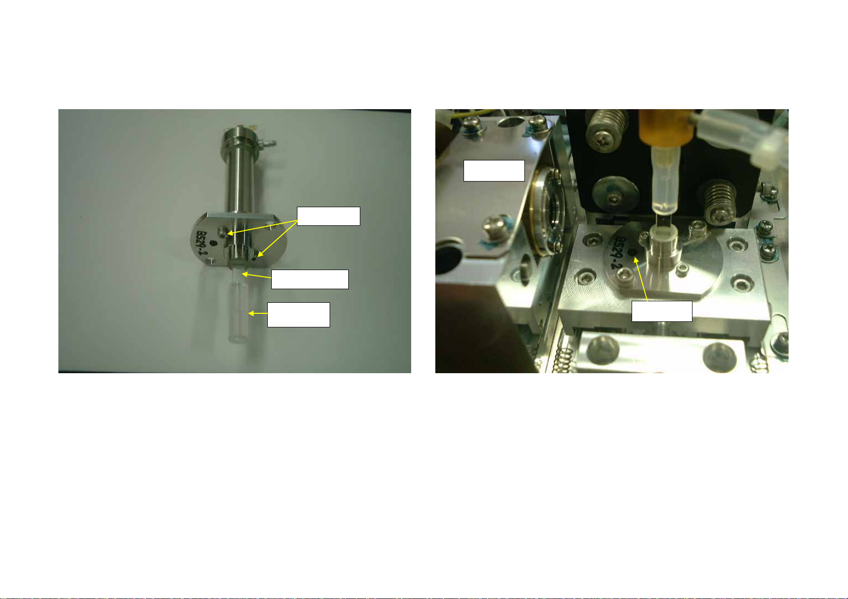
(4) Remove two fixing screws of the flow cell unit. Cut the Tube Silicone
1.5 X 6 when replacing Flow Cell No.22.
Fixing Screws
Flow Cell No.22
(5) After installing new Flow Cell No.22, install the Flow Cell Unit No.10
facing the black dot to laser diode. After installing, connect tubing as
figure in the previous page.
Laser Diode
Tube Silicone
1.5 X6
Black dot
XT Series S/M 4-2
Page 5
(4) Remove two fixing screws of the flow cell unit. Cut the Tube Silicone
1.5 X 6 when replacing Flow Cell No.22.
Fixing Screws
Flow Cell No.22
(5) After installing new Flow Cell No.22, install the Flow Cell Unit No.10
facing the black dot to laser diode. After installing, connect tubing as
figure in the previous page.
Laser Diode
Tube Silicone
1.5 X6
Black dot
XT Series S/M 4-2 December 13, 2007
Page 6

4.2 Optical Alignment (Rough)
Turn on the laser by selecting Menu -> Controller -> Service ->Laser
Power.
Adjust the pin hole position by turning Pin Hole Adjustment Screw so that
the pin hole is center of the Photo Diode.
Pin hole adjustm ent screw
Pin hole
Remove Condenser Lens Unit No.6 by loosening fixing screws.
Fixing
Screws
Condenser Lens Unit No.6
XT Series S/M 4-3 December 13, 2007
Page 7

4.2.1 Laser Diode Adjustment
(1) Adjust the cylinder depth (height) by turning Laser Diode adjustment
Screw so that the cylinder corner and base are same level.
AdjustthecylinderheightbyturningLaserDiodeadjustmentScrew
sothatthecylindercornerandbasearesamelevel..(Ifnot,adjustit.)
LaserDiode
AdjustmentScrew
ReflectionfromFlowCell
Hex-socketscrewdriver
LaserBeamfromLDunit
Flow ce
No.1
ll unit
0
LaerDiode
LensHolder
(2) Turn on the laser by selecting Menu -> Controller -> Service ->Laser
Power. Place the Hex-socket driver between the Flow Cell and the LD
unit as shown in the below figure. If the flow cell angle is correct,
Laser beams from the LD unit and reflection from the Flow Cell
surface are in line on the Hex-socket driver. If not, turn flow cell by
loosening fixing screws of the Flow Cell Unit No.10. After flow cell
angle adjusted, tighten the fixing screws alternately. Turn off the laser
to press OK in the Laser power screen.
Fixing screws
Flow cell
adjustment screw
Hex-socket socket driver
XT Series S/M 4-4 December 13, 2007
Page 8

Double-click the above image to see the movie.
XT Series S/M 4-5 December 13, 2007
Page 9

4.2.2 Installing Condenser Lens Unit No.6
Fixing
Screws
Dowel pins
Condenser Lens Unit No.6
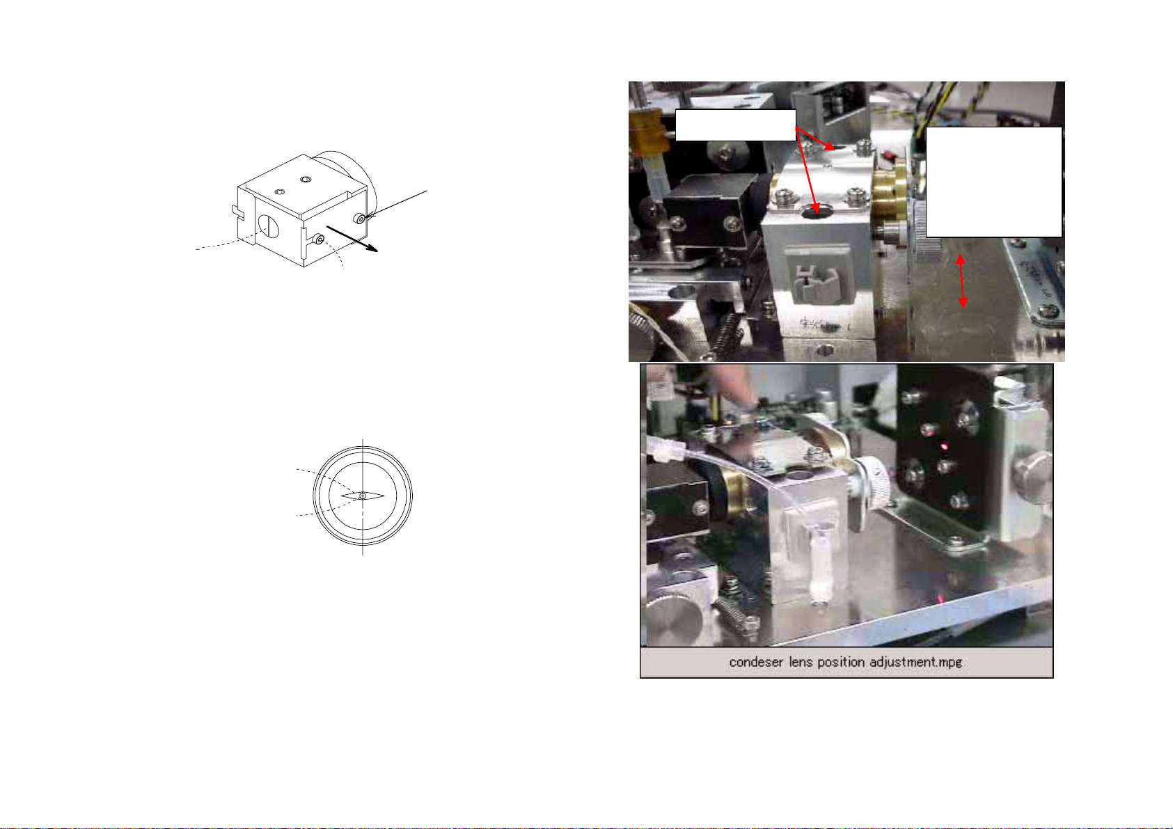
(1) Adjusting Condenser Lens Unit No.6 Position
1) Loosen fixing screw. Adjust the edge of the Lens Holder No.39
and edge of Mirror Tube No.14 is 2-3mm as below by turning
Condenser Adjustment Screw. Install the Condenser Lens Unit
No.6 while pressing to the dowel pins and tighten the fixing screw
temporary.
2-3 mm
Fixing Screws
Condenser Adjustment Screw
2) Turn on the laser by selecting Menu -> Controller -> Service
->Laser Power
3) Loosen locking nut of Flow Cell Adjustment screw and locking
screws for flow cell stage.
Locking Screws
Locking Nut
Flow Cell Adjustment Screw
XT Series S/M 4-6 December 13, 2007
Page 10
4) Turn Flow Cell Adjustment Screw CCW so that the laser beam is
out of the flow cell. Turn Beam stopper adjustment screw so that
the laser beam is out of the beam stopper.
Do not turn this screw
Fixing Screws
Move Condeser
Len Unit No.6
side to side
while pushing
the dowel pins.
Beam Stopper
Beam Stopper Adjustment Screw
5) Move Condenser Lens from side to side while pushing the
Condenser Lens Unit No.6 to the dowel pins so that the center of
the laser beam is in the center of the Photo Detector No.20. If the
vertical position of the laser beam is not correct, adjust the pin hole
adjusting screw to fit the height, then adjust it side to side. Tighten
two fixing screws of Condenser Lens Unit No.6.
Laser
Beam
Pin
Hole
Double-click the above image to see the movie.
XT Series S/M 4-7 December 13, 2007
Page 11

6) Turn Flow Cell Adjustment screw CW so that the laser beam is in
the flow cell. Adjust the laser beam position so that the beam is out
of the flow cell center . A djust the Condenser Lens screw so that the
laser beam on the Photo Diode No.20 is lowest. Adjust the vertical
pin hole adjustment screw so that the laser beam is center of the
pin hole. Do not adjust the horizontal pin hole adjust screws.
XT Series S/M 4-8 December 13, 2007
Page 12

4.2.3 Flow Cell Position Adjustment
(1) Adjust the Flow Cell Adjustment Screw so that the pin hole is in the
center of the flow cell sample path (The distance between flow cell
stage and fixing metal is approx. 8 mm.).
(2)
8 mm
Flow Cell
Adjustment Screw
(2) Observe the laser beam image on the Photo Detector Unit No;20.
When the sample path of the flow cell is not seen clearly, place a
magic mending tape (frosted tape) between flow cell and laser diode
unit. Place white paper in front of the Photo Diode for clear view.
Pin Hole
Laser Beam
Sample Path of the Flow Cell
XT Series S/M 4-9 December 13, 2007
Page 13

Sample Path
Pin Hole
(3) Confirm that the edges of the Flow Cell Sample Path are symmetrical
in image thickness. This will confirm that the flow cell rotation position
adjustment was performed correctly in section 4.1.1.
Double-click the above image to see the movie.
Good Symmetry Poor Symmetry
XT Series S/M 4-10 December 13, 2007
Page 14

4.2.4 Beam Stopper Position adjustment
(1) Turn Beam Stopper Adjustment Screw to find the shadow of the
Beam Stopper. Move Beam Stopper Fixture so that the image of the
flow cell sample path and Beam Stopper are parallel. To see image
clearly, place white paper in front of the Photo Detector No.20To see
image clearly, place a piece of magic mending tape (frosted tape)
between flow cell and laser diode. To see image clearly, turn off the
light.
(2) Turn Beam Stopper Adjustment Screw so that the center of the Beam
Stopper Image and pin hole are same.
Laser Beam on
the Beam St opper
Beam Stopper
Adjustment Screw
Pin hole
Sample Path of
the Flow Cell
Image of the
Beam Stopper
Beam Stopper
Fixture fixi ng
screws
Push Beam Stopper
Fixture lightly to this
direction while
tightening the screws
Image of
Beam Stopper
(3) Remove white paper in front of the Photo Detector No.20. Remove
the mending tape between flow cell and laser diode.
(4) Turn off the laser to press OK in the Laser power screen.
Move Beam
Stopper Fixture
Too much
tightening sti f fen
beam stopper
Beam Stopper
Adjustment Scr ew
XT Series S/M 4-11 December 13, 2007
Page 15

4.2.5 Florescence light adjustment (rough)
(1) Turn Condenser Lens Unit No.7 adjustment screw (B/F) so that
distance between condenser lens and flow cell is approx. 1mm. Do
not touch the lens to flow cell. Adjust the Condenser Lens No.7 so
that the lens position is as below. Loosen locking screws to move
Condenser Lens Unit No.7.
Locking Screws
Condenser
Lens Unit No.7
Locking Nut
Flow Cell Adjustment Screw
Condenser Lens Position
Adjustment Screw (F/B)
The edge of the lens is
same height of the top
of the flow cell.
XT Series S/M 4-12 December 13, 2007
Page 16

4.2.6 Preparation of Optical Alignment (fine)
(1) Adjusting laser power
1) Turn Flow Cell Adjustment Screw CCW so that the laser beam is
out of flow cell.
2) Turn VR1 on PCB No2161 CCW fully.
3) Start the IPU with factory maintenance mode.
4) Turn on the laser by selecting Service ->Laser Power
5) Adjust the laser power by turning VR1 on PCB No.2161 so that 3.4
+/- 0.1mW is observe on the power meter (wave length: 633 nm).
6) Press Back -> Menu to display measurement window.
(2) Priming Reagent
1) Press start switch and confirm that no leakage is occurred.
2) Run Air Bubble Removal by selecting
Menu->Controller->Maintenance->Air Bubble Removal.
3) Press Cancel to display measurement window.
4) Press Start Switch without aspirating sample to confirm that RET#
is less than 0.3 X 10^4/uL.
5) After one cycle, observe no bubble at the flow cell.
(3) Settings of the Oscilloscope
CH1: Side Florescence light (SFL) Connect to TP21 (SFL) and TP24
(A GND) on PCB No.2158.
CH2: Front Scattered light (FSC) Connect to TP15 (FSC) and TP24
(A GND) on PCB No.2158.
[Settings]
VOL TS/DIV CH1: 20-50 mV, CH2: 20-50 mV, TIME/DIV 0.2-0.5 us/div
TRIGGERING SOURCE: SFL: CH1, FSC: CH2, (INV ON, SLOPE
OFF)
[PMT voltage setting]
Set Side Florescence light (SFL) voltage 300 +/- 50 V.
PCB No.2161 Drawing
XT Series S/M 4-13 December 13, 2007
Page 17

SFL(TP21)
SSC(TP18)
FSC(TP15)
PCB No.2158 Drawing
XT Series S/M 4-14 December 13, 2007
Page 18

May 23, 2008
4.2.7 Procedure for Optical Axis Adjustment Procedure
(1) Preparing Latex for Optical Alignment
Fixing
Screws
1) Latex for FSC
Dilute 2 drops of latex SS
-071-P with CELLPACK 30mL.
Dilute 6 drops of latex particles 4207A with CELLPACK 30mL.
NOTE) Produced latex for FSC is usable only one day. Do not use
after the day.
2) Latex for SFL
Dilute 2 drops of latex A-7312 with CELLPACK 50mL.
NOTE) Produced latex for FSL is usable within three hours.
Do not use after that.
(2) Select Menu->Controller->Service-> Service Sequence->Optical Axis
Adjustment (Rough).
(4) Press Start switch to aspirate Latex for FSC from the manual
aspiration pipette.
Condenser Lens Unit No.6
(3) Loosen fixing screws for Laser Diode and Condenser lens unit for
adjusting optical alignment.
Fixing Screws
Laser Diode Unit
XT Series S/M 4-15
Page 19

4.3 Optical Axis Alignment (Fine)
4.3.1 Front Scattered Light (Fine)
Adjust each adjustment screws so that the wave height is highest and
uniform.
(1) Provisional Adjustment
When the latex wave is disorder or low, run Optical Axis Alignment
two or three times to adjust temporary. Adjust the position of laser
diode, condenser lens and flow cell to observe the wave easily.
Adjust so that the wave is
V
t
Before Provision Adjus tment After Provision A djustment
V
(2) Laser diode adjustment
1) Adjust laser diode adjustment screw so that the wave width is
narrowest and wave height is highest and uniformed.
uniformed to be easily observed
t
V
Tighten sc r ews
alternately
t
W
Laser Diode
Adjustment Screw
2) Tighten screws on the Laser Diode not to widen the wave width.
Tighten screws alternately not to move the laser diode. Adjust the
pin hole position of the Photo Detector Unit No.20 so that the laser
beam is center of the pin hole by adjusting vertical adjustment
screw. Do not adjust the horizontal pin hole adjustment screws.
3) If the wave height is lowered or disordered, adjust pin hole height
and flow cell side to side position.
Shadow of
Beam Stopper
Pin hole
Reflect from the sample
path of the flow cell
XT Series S/M 4-16 December 13, 2007
Page 20

May 23, 2008
(3) Condenser Lens No.6 Adjustment (Fine)
1) Adjust adjustment screw of the Condenser Lens No.6 so that the
wave height is highest.
2) Tighten fixing screws on the Condenser Lens No.6 alternately.
3) If the wave height is lowered or disordered after tightening fixing
screws, adjust pin hole height and flow cell side to side position Do
not adjust the horizontal pin hole adjustment screws.)
(4) Photo Detector No.20 Adjustment (Fine)
1) Adjust vertical adjustment screw adjustment screw of the Photo
Detector No.20 so that the wave height is highest and uniformed.
2) Tighten four fixing screws of Photo Detector Unit No.20 in order of
a-d-b-c.
a
c
(5) Flow cell adjustment
1) Select Optical Axis Adjustment (Fine).
2) Adjust flow cell adjustment screw so that the wave height is
highest and uniformed.
3) Confirm below values.
FSC(W) is 0.16 or less
4) Confirm that the FSC(X) is 130±50 in the Optical Axis Adjustment
(Fine) screen. If the value is not within the range, enter a value in
the FSC Gain box so that the FSC(X) is 130 ± 50.
5) Adjust flow cell adjustment screw and pinhole horizontal
adjustment screws so that the wave height is highest and
uniformed. When flow cell adjustment screw is moved, be sure to
adjust pinhole horizontal screws.
b
d
6) Confirm that the pinhole is in the center of the beam stopper
shadow. If the pinhole is not in the right position, adjust beam
stopper position. Do not touch beam stopper position after this
adjustment.
(6) Flow Cell Adjustment
1) Adjust flow cell adjustment screw so that the wave height is
highest and uniformed again.
2) Then tighten locking nut of the flow cell adjustment screw by 30 or
40 degrees using a tool. During this tightening, hold the flow cell
adjustment screw by fingers not to move. After tightening, confirm
that the FSC(W)< 0.180.
3) Tighten locking screws.
4) Reconfirm below values.
FSC(W) is 0.16 or less
5) Reconfirm that the FSC(X) is 130 ± 50.
(7) Confirmation of Flow Cell Adjustment
1) Run latex SS-071-P (diluted 10 times with CELLPACK) as a
patient in the manual mode. Confirm the WBC/BASO scattergram
is concentrated as shown below. If the scattergram is not good,
perform the optical alignment from section 4.1.1 Adjust Flow Cell
Angle.
Good example Bad example
XT Series S/M 4-17
Page 21

Good Example (e-CHECK Level 2)
Good Example FSC (Latex)
XT Series S/M 4-18 December 13, 2007
Page 22

Locking Screws
Condenser
Lens Unit No.7
Locking Nut
Flow Cell Adjustment Screw
(6) Side florescence adjustment (Fine)
1) Select Optical Axis Adjustment (Rough).
2) Press Start switch to aspirate Latex for SFL from the manual
aspiration pipette.
3) Adjust each adjustment screws so that the wave height is highest
and uniform.
4) Adjust Condenser Lens Unit No.7 vertical adjustment screws so
that the wave height is highest and uniform.
5) Adjust Condenser Lens Unit No.7 horizontal adjustment screws so
that the wave height is highest and
Vertical adjustment screw
Horizontal
adjustment screw
Condenser
Lens Unit No.7
uniform.
6) Adjust Condenser Lens Unit No.7 Forward/Backward adjustment
screws so that the wave height is highest and uniform.
Condenser
Lens Unit No.7
Condenser Lens
Fowared/Backward
Adjustment Screw
XT Series S/M 4-19 December 13, 2007
Page 23

7) Repeat step 3) – 5) so that the wave height is highest and uniform.
8) Adjust Socket unit direction so that the wave height is highest and
uniform. When Socket unit is tuned fully, adjust PMT socket
direction.
Socket Assembly
When fixing screw is
loosened, adj ust the
Socket assembly while
pulling up the socket .
Locking Screw
Vertical
Adjustment Screw
Photo Detector
No.22
Locking Screw
Fixing Screw
Photo Detector No.21
9) Select Optical Axis Adjustment (Fine). Confirm that the SFL(X) is
130 +/- 50. If the SFL(X) is not within the range, enter a value in the
SFL Gain so that the SFL(X) is 130 +/- 50.
10) Examine below values.
SFL(W)< 0.410
(7) Side Scattered adjustment (Fine)
1) Change the CH1 probe as follows. CH2 remained same.
CH1: Side Scattered (SSC) TP18 (SSC: signal) and TP24 (A
GND): signal on PCB No2158 (Setting remain unchanged.)
2) Loosen fixing screw of Photo Detector Unit No.22 and Optical
base.3) Loosen locking screws.
Optical Base
Fixing Screw
4) Select Optical Axis Adjustment (Rough).
5) Press Start switch to aspirate Latex for SFL from the manual
aspiration pipette.
6) Adjust Photo Detector side to side position so that the wave height
is highest and uniform as follows.
a) Mark a line of the position of Photo Detector No.22 and Optical
Base with an extrafine-pointed pen when Photo Detector No.22 is
moving to the left and the waveform becomes out of order.
Assume that the mark on the Photo Detector No.22 is A and the
mark on Optical Base is B.
b) Mark a line of the position of Photo Detector No.22 and Optical
Base with a extrafine-pointed pen when Photo Detector No.22 is
moving to the right and the waveform becomes out of order.
Assume that the mark on the Optical Base is C. The distance
between B and C will be approximately 2 mm.
)
c) Adjust the Photo Detector left/right position so that the A is the
center of the B and C.
After adjusting the position, tighten the fixing screws.
XT Series S/M 4-20 December 13, 2007
Page 24

7) Adjust Photo Detector vertical position so that the wave height is
highest and uniform as follows.
a) Mark a line of the position of Photo Detector Mounting Plate
No.3-A and Detector Mounting Plate No.3-B with an
extrafine-pointed pen when Photo Detector No.22 is moving to the
up and the waveform becomes out of order. Assume that the mark
on the Photo Detector Mounting Plate No.3-B is D and mark on
the Photo Detector Mounting Plate No.3-A is E.
b) Mark a line of the above D and Photo Detector Mounting Plate
No.3-A with an extrafine-pointed pen when Photo Detector No.22
is moving to the down and the waveform becomes out of order.
Assume that the mark on the Photo Detector Mounting Plate
No.3-A is F. The distance between E and F will be approximately 2
mm.
c) Adjust the Photo Detector up/down position so that the D is the
center of the E and F.
d) After adjusting the position, tighten the fixing screws for up/down
position.
8) Adjust forward/backward adjustment screw of Condenser lens unit
No.7 so that the wave height is highest and uniform.
9) Repeat step 1) to 3) to get the wave height is highest and
uniformed.
10) After adjustment, tighten locking screws and fixing screws of
Photo Detector Unit No.22.
11) Tighten locking screws.
12) Tighten nut of the forward /backward adjustment screw.
13) Examine below values.
SFL(W)< 0.410
14) Confirm that the SFL(MFV) is 130 +/- 50.
15) Select Optical Axis Adjustment (Fine). Examine below values.
SSC(W)< 0.410
SSC(X)>30
Good Example SFL (Latex)
XT Series S/M 4-21 December 13, 2007
Page 25

4.4 Electric Adjustment
4.4.1 PCB No.1260
(1) Jumper pin settings
[Synchronous serial settings]
Synchronous serial signal can be used with multiple PCB. When
additional PCB is added subsequently, jumper setting should be
changed as follows.
Connector 1-2 Short circuit 2-3 Short circuit
J19 No Additional PCB Additional PCB added
On XT-2000i, set to 1-2 short circuited.
[Voltage setting of Constant voltage drive motor]
The voltage of constant voltage drive motor can be switch 12V or 5V.
Connector 1-2 Short circuit 2-3 Short circuit
J25 Motor Driven Voltage 5V Motor Driven Voltage
12V
On XT-2000i, set to 1-2 short circuited.
(2) Adjusting Blood Sensor
1) Confirm that SNS23 is red without placing a test tube in front of the
blood sensor. Place 15 mm diameter test tube with 2 mL water to a
Rack and shift it to blood sensor position.
2) If SNS23 is gray (or D34 is fully lit), Jump to step 3). If SNS 23 is
red, turn VR1 on PCB No.1260 CCW so that SNS23 turns to gray.
3) Place empty 15 mm diameter test tube to a rack and confirm that
SNS23 is red (or D34 is dimly lit) when the test tube is in front of
the blood sensor. (Use empty 12 mm diameter test tube if the
customer uses this type of test tube.)
4) If SNS23 does not turn red (or D34 is not dimly lit), turn VR1 on
PCB No.1260 CW so that SNS23 turns to red.
5) Repeat above steps for verification.
NOTE: With 2 mL test tube: Gray, With empty test tube: Red
XT Series S/M 4-22 December 13, 2007
Page 26

(3) LED and Test Point
[LED]
LED Indication Function
D 1 R-5 Reagent Prism Sensor (EPK)
D 2 R-4 Reagent Prism Sensor (FBT)
D 3 R-3 Reagent Prism Sensor (FFD)
D 4 R-2 Reagent Prism Sensor (SLS)
D 5 R-1 Reagent Prism Sensor (RED)
D 13 PUMP-E Blood sensor (Whole Blood pump side) error: lit
D 14 B-P2 Blood sensor (Whole blood pump side level: H)
D 15 B-P1 Blood sensor (Whole blood pump side level: L)
D 16 CP-E Blood sensor (CP side) error: lit
D 17 B-CP2 Blood sensor (CP side level: H)
D 18 B-CP1 Blood sensor (CP side level: L)
When thermistor wire broken (sheath reagent t emperatur e
D 19 FCM-E
D 20 ENV-E
D 21 REAC-E
D 22 HAET-E
D 23 FMT-E
D 27 HEAT When reaction chamber heater on: lit
D 28 REAC When reagent heater on: lit
D 29 FMT When PMT heater on: lit
D 34 T-BLOOD When blood detection sensor detects sample: lit
detection): lit
When thermistor wire broken (ambient temperature
detection): lit
When thermistor wire broken (reagent heater temperature
detection): lit
When thermistor wire broken (reaction chamber
temperature detection): lit
When thermistor wire broken (PMT temperature
detection): lit
D13 and D16: Blood sensor level H: When a bubble(s) passed: lit
(Sensor monitors just before aspirating sample. The sensor is
automatically adjusted using EPK.)
D14, D15, D17 and D18: Blood sensor level L: When sample
passes: lit (Sensor monitors just before rotating the SRV.)
[Test Points]
Indication Function
TP 1 PUMP Blood sensor (Whole blood pump side) voltage
TP 2 CP Blood sensor (CO side) voltage
TP 3 12V-A Voltage for analog signal: 12V
TP 4 A.GND A.GND
TP 5 ENV AD converter for ambient temperature thermister input voltage
TP 6 SEATH AD converter for sheath reagent thermistor input volage
TP 7 REAC AD converter for reagent heater thermister input voltage
TP 8 HEAT AD converter for reaction chamger thermister input voltage
TP 9 FMT AD converter for PMT thermister input voltage
TP 10 T-BLOOD Blood detection sensor input signal
TP 11 VCC Voltage Vcc
TP 12 D.GND D.GND
TP 13 12V Voltage 12V
TP 14 24V Voltage 24V
XT Series S/M 4-23 December 13, 2007
Page 27

4.4.2 PCB No.6365
(1) Dip Switch
bit ON OFF Default
1 Connect Conveyer Not Connect Conveyer OFF
2 Sampler connected Not Sampler connected ON
3 Zero padding for HST Not Zero padding for HST OFF
4 Connect Bar Code
Reader
5 Initialize setting data in
EEPROM at power ON
6 Output debugger
Not output debugger
informaion
Not Connect Bar Code
Reader
Not Initialize setting data in
EEPROM at power ON
information
7 XT-1800i XT-2000i OFF
8 Initialize counters in
EEPROM at power ON
Not Initialize counter in
EEPROM at power ON
OFF
OFF
OFF
OFF
XT Series S/M 4-24 December 13, 2007
Page 28

4.5 Sensitivity Adjustment
(1) Select Mode by selecting Menu->Controller->Service->Mode and
mark control 3 in the Analytical Mode.
(2) Select Manual from tool bar, CBC+DIFF+RET in discrete and select
Manual mode, then press OK.
(3) Run Auto rinse. After Auto rinse is over, confirm that no background
error occurs.
(4) Analyze e-CHECK (level 2) in manual mode.
(5) After analysis completes, select Sensitivity by selecting
Menu->Controller->Service-> Sensitivity.
(6) Confirm that the analyzed values are in the below table range.
(7) If the analyzed value is not within the range, change the value in the
sensitivity screen as below steps.
Parameters Target value: Parameter to be adjusted
RBC-X Assayed value +/- 1ch RET(SFL)
RBC-Y Assayed va lue +/- 3ch RET(FSC)
DIFF-X Assayed value +/- 3ch DIFF(SSC)
DIFF-Y Assayed value +/- 2ch DIFF(SFL)
BASO-X Assayed value +/- 3ch BASO(SSC)
BASO-Y Assayed value +/- 2ch BASO(FSC)
(MCV) Assayed value +/- 1 fl RBC gain
(MPV) Assayed value +/- 1fL PLT gain
Blank 20.00 +/- 2.0 HGB Blank
Sample Assayed value +/- 0.2 g/dL HGB span
*Check the value in the data browser screen.
XT Series S/M 4-25 December 13, 2007
Page 29

Measured Value
The value of digital
potentiometer
2175
*2
*2
*2
*2
135
135
1680
*2
*1
*2
*1
*1
*1
(8) For RBC-Y, BASO-Y, MCV and P-MFV, enter target value in the *1 box and press “>>>”, then digital potentiometer is automatically calculated.
Press Send to reflect the digital potentiometer.
(9) For RBC-X, DIFF(SSC), DIFF(SFL), BASO(SSC), HGB blank and HGB span, enter values in the *2 boxes for digital potentiometer to change the
sensitivity. Press Send to reflect the sensitivity.
(10) If the values are not in the range of table above repeat step (8) or step (9).
XT Series S/M 4-26 December 13, 2007
Page 30

4.6 HGB Blank Convert Value Adjustment
(1) Confirm that 30 minutes past after turning on the main unit.
(2) Select Sensitivity by selecting Menu->Controller->Service->
Sensitivity.
(3)Change the value in the HGB Blank box so that the blank value be
20.00 +/-5.0.
1) Enter appropriate value in the HGB Blank box and press Send.
2) Repeat above step so that the Blank value be in the range.
(Default value: 160)
4.7 RBC Clog Level Adjustment
(1) Select RBC Clogs by selecting Menu->Controller->Service->RBC
Clogs, RBC clog level is displayed in real time.
(2) Enter “100” in the target then press “>>>” and Send.
(3) Repeat above step so that the clog level be in the range of 98 –
102.
XT Series S/M 4-27 December 13, 2007
Page 31

4.8 CP Unit Position Adjustment
(1) Remove CP Cover by loosening two thumb screws.
(2) Remove front lower cover by removing four screws. (Loosen two
screws in dashed circles.)
(3) Place a sample rack with Alignment Tool A at the position 1.
Alignment Tool A
(4) Feed in the rack by selecting Menu
Æ Controller Æ Maintenance Æ
Rack Feed in.
(5) Shift the rack three steps by operating “Rack Feed in” three times to
move the Alignment Tool A in front of the hand clipper.
(6) Move the hand clipper toward you by selecting Menu
Service
Æ CP Æ Front. Place Alignment Tool B at the hand clipper
so that the two Alignment tools touch.
Alignment Tool B
(7) Loosen 6 fixing screws on the CP Unit.
Æ Controller Æ
XT Series S/M 4-28 December 13, 2007
Page 32

(8) Adjust CP position so that the tips of the two Alignment tools are
exactly aligned. Move the CP Unit chassis so that the CP Unit
chassis is parallel to the Main Unit chassis.
(9) After competing adjustment, tighten 6 fixing screws loosened in step
7.
(10) Move the hand clipper toward you by selecting Menu
Æ Controller
Æ Service Æ CP Æ Front. Adjust the position of the Sample Tube
Flicking Metal No.3 so that it comes center of the hand clippers.
Sample Tube Flicking Metal No.3
Mount the Front lower cover.
(11)
Mount the CP cover. If the CP cover touches to the front cover,
(12)
adjust the Cover Mounting Plate No.46 right and left position.
Cover Mounting Plate No.46
XT Series S/M 4-29 December 13, 2007
Page 33

4.9 CP Piercer Position Adjustment
(1) Remove CP cover by loosening two upper thumb screws.
(2) Place an empty blood collection tube at the position 1 of a rack as
shown.
XT Series S/M 4-30 December 13, 2007
Page 34

(3) Shift the rack manually to the leftward so that the blood collection
tube is in front of the hand clipper.
(4) Run “Rotate” by selecting service
Æ CP.
(5) Place a ruler at the piercer needle and confirm that the needle is in
the center of the tube and parallel.
XT Series S/M 4-31 December 13, 2007
Page 35

(6) If the needle is not proper position, adjust the needle position by
loosening three screws so that the needle is center and parallel to the
tube as shown.
(7) Return the tube to the initial position by selecting “Initial Position”.
Affix an adhesive tape on the opening of the tube and run “Clamp &
Piercer”.
XT Series S/M 4-32 December 13, 2007
Page 36

(8) Return the tube to the initial position by selecting “Initial Position”.
Check the pierced hole is in the center of the tube. If it is not in the
center, adjust it again.
(9) If the position of the pierced hole is not center in a back-and-forth
direction, follow the procedures below to adjust piercer position.
1) Remove Cover Mounting Metal No.49 by loosening screws as
shown.
XT Series S/M 4-33 December 13, 2007
Page 37

2) Loosen four screws as shown.
3) Remove Hgb Detector block by removing one thumb screw.
XT Series S/M 4-34 December 13, 2007
Page 38

4) Loosen two M4 hex screws and adjust the piecer unit position so
that the piecing position is in the center of the tube. Fix the hex
screws temporally after adjustment.
(10) After adjustment, affix an adhesive tape on the opening of the tube
again, and confirm that the pierce hole is in the center of the tube by
selecting “Clamp & Piercer. ” When the pierced hole is in the center
of the tube, tighten all fixing screws.
XT Series S/M 4-35 December 13, 2007
Page 39

4.10 Sensitivity Adjustment Procedure (Europe only)
4.10.1 Introduction
During installation, after Optical Axis Alignment and in case of poor
sensitivity control blood data, sensitivity adjustment should be performed
for XT-2000i field analysers with the following procedures. These
procedures are mostly in accordance to section 4.2.1 Service Manual.
However this procedure as it is described here uses human blood
samples for three parameters (NEUT-Y, WBC/BASO-Y and RBC-X), as
these are not stable enough for use with control blood adjustment.
Following optical sensitivity parameters need to be adjusted:
a) DIFF-X (X-axis of DIFF channel)
b) NEUT-Y (Y-axis of DIFF channel)
c) BASO-X (X-axis of WBC/BASO channel)
d) BASO-Y (Y-axis of WBC/BASO channel)
e) RBC-X (X-axis of RET channel)
f) RBC-Y (Y-axis of RET channel)
(1) First, using fresh whole blood samples, the following 3 sensitivity
parameters are to be adjusted.
a) NEUT-Y (Y-axis of DIFF channel)
b) WBC/BASO-Y (Y-axis of WBC/BASO channel)
c) RBC-X (X-axis of RET channel)
(2) The other 3 sensitivity parameters are to be adjusted using e-CHECK
(Level 2).
(You can find the value in the NPP / Assay Sheets)
a) DIFF-X (X-axis of DIFF channel)
b) BASO-X (X-axis of WBC/BASO channel)
c) RBC-Y (Y-axis of RET channel)
The fresh whole blood samples used for adjustment purpose, should
meet the following specifications:
a) Criteria for fresh whole blood samples
HGB: 120 - 160 g/l
PLT: 150 – 450 x 10
MCV: 85 - 105 fl
WBC: 5.5 – 9.5 x 10
9
/l
9
/l
Neut: 55 – 78%
Lymph: 20 – 30%
Mono: 2 – 10%
Eo: 0 – 5%
Baso: 0 – 2%
No WBC-Suspect Flags
Retics in normal range
b) Anti-coagulant: EDTA-2K or EDTA-3K should be used.
c) No turbidity should be observed.
Concerning the name of each sensitivity parameter, refer to
corresponding channel parameters as displayed in the Service Menu.
Concerning the detailed procedures, perform sensitivity adjustment
according to adjustment protocol as printed in the Service Manual.
For efficient adjustment procedure, perform it in the following order:
DIFF
Æ WBC/BASO Æ RET channel
Note: Some values marked with * differ from the acceptable limit
ranges as printed in the Service Manuals
XT Series S/M 4-36 December 13, 2007
Page 40

4.10.2 Sensitivity Adjustment for DIFF channel
4.10.2.1 Fresh Whole Blood Samples
(1) Prepare 20 fresh whole blood samples according to the criteria written
in the introduction above.
(2) Run 20 fresh whole blood samples consecutively (once per sample)
within four hours after collection and calculate the truncated Mean
(M1) and SD (SD) for the following parameter: (Human blood has to
be measured with the profile "other1" in case XT-2000iV/XT-1800iV
software is installed.)
NEUT-Y (Y-axis of DIFF channel)
(3) Remove the data showing outside Mean+/- 1.5SD and re-calculate
the Mean (M2).
(4) Verify if the M2 for NEUT-Y is within the following ranges:
Parameter Target Value (ch) Acceptable Range (ch)
NEUT-Y 43.5 +/- 2.0
(5) If the fresh whole blood samples data are outside the above range,
perform the pre-adjustment with
e-CHECK (Level 2). (Refer to XT-2000i S/M section 4.4 for detailed
procedures, change to CTRL3 mode)
Channel
DIFF channel
Y-axis
Sensitivity Parameter
e-CHECK Whole Blood
DIFF-Y NEUT-Y Value in Sensitivity
Samples
Adjustment Point
screen
Note: The purpose of the pre-adjustment with e-CHECK is to keep the
adjustment practicable.
(6) After pre-adjustment with e-CHECK, run the whole blood samples
again (repeat steps 2 - 4.)
(7) Verify that data of NEUT-Y are within the specified limits. If it fails,
repeat step 5 - 7 until it meets the specs.
4.10.2.2 e-CHECK (Level 2)
(1) Prepare one vial of e-CHECK (Level 2).
(2) Run e-CHECK 5 times consecutively and calculate the Mean (M1)
and SD (SD) for DIFF-X.
(3) Remove the data showing outside Mean+/- 1.5SD and re-calculate
the truncated Mean (M2).
(4) Verify if the M2 meets the following criteria of the XT-2000i assay
sheet:
Parameter Target Acceptable Range
DIFF-X XT-2000i assay data +/- 3.0 (ch)
(5) If it fails, perform the sensitivity adjustment for DIFF-X according to
the S/M section 4.4.
XT Series S/M 4-37 December 13, 2007
Page 41

4.10.3 Sensitivity Adjustment for WBC/BASO channel
4.10.3.1 Fresh Whole Blood Samples
(1) Prepare 20 fresh whole blood samples according to the criteria written
in the introduction above.
(2) Run 20 fresh whole blood samples in Normal Open Mode
consecutively (once per sample) within four hours after collection and
calculate the truncated Mean (M1) and SD (SD) for the following
parameter
WBC/BASO-Y (Y-axis of BASO channel). Remove outliers from
the data set before the calculation of the mean Baso-Y value.
(3) Remove the data showing outside Mean+/- 1.0 SD and re-calculate
the Mean (M2).
(4) Verify if the M2 for WBC/BASO-Y is within the following ranges:
Parameter Target Value (ch) Acceptable Range (ch)
WBC/BASO-Y 72.0 +/- 3.5
(5) If the fresh whole blood samples data are outside the above range,
perform the pre-adjustment with e-CHECK (Level 2). (Refer to
XT-2000i S/M section 4.4 for detailed procedures, change to CTRL3
mode.)
Sensitivity Parameter Channel
e-CHECK Whole Blood
Samples
WBC/BASO
BASO-Y WBC/BASO-Y Value in Sensitivity
Y-axis
Note: The purpose of the pre-adjustment with e-CHECK is to keep
the adjustment practicable
.
Adjustment Point
screen
(6) After pre-adjustment with e-CHECK, run the whole blood samples
again (repeat steps 2 - 4.)
(7) Verify that data of WBC/BASO-Y are within the specified limits. If it
fails, repeat step 5 - 7 until it meets the specs.
4.10.3.2 e-CHECK (Level 2)
(1) Prepare one vial of e-CHECK (Level 2).
(2) Run e-CHECK (Level 2) 5 times consecutively and calculate the
Mean (M1) and SD (SD) for BASO-X.
(3) Remove the data showing outside Mean +/- 1.0 SD and re-calculate
the Mean (M2).
(4) Verify if the M2 are within the following criteria of the XT-2000i assay
sheet:
Parameter Target Acceptable Range
BASO-X XT-2000i assay data +/- 2.0 (ch)
(5) If it fails, perform the sensitivity adjustment for BASO-X according to
the S/M section.
XT Series S/M 4-38 December 13, 2007
Page 42

4.10.4 Sensitivity Adjustment for RET channel
4.10.4.1 Fresh Whole Blood Samples
(1) Prepare 20 fresh whole blood samples according to the criteria written
in the introduction above.
(2) Run 20 fresh whole blood samples consecutively (once per sample)
in Normal Open Mode and calculate Mean (M1) and SD (SD) for the
following parameter:
RBC-X (X-axis of RET channel)
(3) Remove the data showing outside Mean +/- 1.5 SD and re-calculate
the truncated Mean (M2).
(4) Verify if the M2 for RBC-X is within the following ranges:
Parameter Target Value (ch) Acceptable Range (ch)
RBC-X 17.7 +/- 1.0
(5) If the fresh whole blood sample data are outside the above range,
perform the pre-adjustment with e-CHECK (Level 2). (Refer to
XT-2000i S/M for detailed procedures, change to CTRL3 mode.)
Sensitivity Parameter Channel
RET channel
X-axis
e-CHECK
(Level 2)
RBC-X RBC-X Value in
Whole Blood Samples
Note: The purpose of the pre-adjustment with e-CHECK is to
keep the adjustment practicable.
(6) After doing pre-adjustment with e-CHECK (Level 2), run the whole blood
samples again (repeat step 2-4)
Adjustment
Point
Sensitivity
screen
(7) Verify that the data (RBC-X) are within the above specifications. If it
fails, repeat step 5 - 7 until it meets the specs.
4.10.4.2 e-CHECK (Level 2)
For RBC-Y
(1) Prepare one vial of e-CHECK (Level 2).
(2) Run e-CHECK (Level 2) 5 times consecutively, and calculate Mean
(M1) and SD (SD) for the following parameter:
RBC-Y (Y-axis of RET channel)
(3) Remove the data showing outside Mean +/- 1.0SD and re-calculate
the truncated Mean (M2).
(4) Verify if the M2 are within the following criteria:
Parameter Target Acceptable Range
RBC-Y XT-2000i assay data +/- 2.0 (ch)
(5) If it fails, perform the sensitivity adjustment for RBC-Y according to
the 4.4 Sensitivity Adjustment.
XT Series S/M 4-39 December 13, 2007
Page 43

4.11 Count Calibration Procedure (Europe only)
4.11.1 Introduction
The XT -2000i uses two different channels, which yield a tot al WBC count,
two channels with RBC, and PLT counts and three different
measurement modes (Manual Open Mode, Sampler Mode and Capillary
Mode) which need to be cross calibrated for correct analytical results.
The correct calibration of different channel results is essential for correct
flagging, as it indirectly influences the sensitivity of certain flags.
4.11.2 Calibration Overview
Following calibration steps are to be performed during installation
procedure and upon requirement when instrument performs out of
controls or major components have been replaced for service purpose.
4.11.2.1 Master Mode Calibration (Open Manual Mode)
(1) CBC Calibration
The master mode calibration is the basic calibration and used as
primary basis for all following calibration steps. It is applicable to the
CBC parameters and reference count channels, wherever same cell
types are counted in different channels (e.g. WBC).
There are two possibilities (materials) to perform the master mode
calibration, one is the use of fresh blood samples using reference
methods and/or counters, which might be very labour intensive and
time consuming. The other more practicable method is to use
SCS-1000, the Sysmex Calibrator System material, which is
traceable to reference methods.
The following table lists all parameters and materials to be used for
the master mode calibration.
Parameter Device Material Method Person Comment
HGB IPU
HCT
HGB IPU
RBC IPU
PLT IPU
WBC IPU
IPU SCS-1000/
Cal-File
Cal-File
Cal-File
Cal-File
SCS-1000/
fresh blood
samples
fresh blood
samples
SCS-1000 SCS-1000 Service
SCS-1000 SCS-1000 Service
SCS-1000 SCS-1000 Service
SCS-1000 SCS-1000 Service
SCS-1000/
reference
methods
SCS-1000/
reference
methods
User Calibration check
User Calibration check
technician
technician
technician
technician
to be done
routinely
to be done
routinely
Primary
HGB-calibration
During installation
During installation
During installation
The first two calibration procedures can be performed through the user .
Calibration status should be checked routinely by means of reference
methods SCS-1000.
Count calibration check has to be performed during installation and
after certain service maintenance procedure, which might have impact
to the count calibration status of the analyser (e.g. changing the whole
blood aspiration tube, or SRV). You can get in IPU_INI,
[IPU_System_Setting], Calibrator_Calibration=1 (0=initial), to perform
calibration of these parameter automatically.
XT Series S/M 4-40 December 13, 2007
Page 44

(2) WBC-count calibration
After analyses of fresh blood samples for the mode-to-mode
calibration, the WBC count of WBC/BASO channel represents the
WBC reference result of XT-2000i and is printed on the report. As
there is another channel which also give a WBC total result, this have
to be cross-calibrated to the reference count as obtained during
master mode calibration.
The table shows the details for the WBC-channel calibration.
Parameter Device CAL
Material Reference Comment
Name
WBC#(DIFFch) IPU
Cal-File
DIFF_CAL Fresh blood WBC# During
installation
Note: All calibration procedures are to be performed by experienced
technical specialists!
(3) Calibration of Optical Parameters
The RBC and PLT count of the HDF Impedance channel represent
the RBC/PLT reference results of XT-2000i and these are printed on
the report (in some particular cases, PLT-O is reported instead of
PLT-I). As there is another channel, which also gives RBC and PLT
total results, the RET-channel, these results have to be
cross-calibrated to the respective reference counts as obtained
during master mode calibration.
The table shows the details for the calibration of the optical
parameters.
Parameter Device CAL Name Material Reference Comment
RBC-O# IPU
Cal-File
PLT-O IPU
Cal-File
RBCO_CAL Fresh blood RBC During
installation
PLTO_CAL Fresh blood PLT During
installation
Note: All calibration procedures are to be performed by experienced
technical specialists!
(4) Calibration of other Parameters
There are several other parameters, which could be calibrated as they
are listed in the calibration file of the IPU. However, the calibration of
these parameters should generally
not be changed as it might have an
impact to the overall WBC differential and flagging performance of the
analyser. In any case the calibration should only be changed after
consultation of the responsible product specialist and in accordance
with the respective customer’s requirements. The following table shows
the parameters and details of the calibration methods to be used.
Parameter Device CAL Name Material Reference Comment
RET IPU
CD n.a. CD_CAL n.a. n.a. n.a.
LFR/MFR IPU
LYMPH,
MONO, EO,
BASO
MONO_B IPU
RET_CAL Fresh blood Manual or
Cal-File
Cal-File
IPU
Cal-File
Cal-File
LFR_CAL
MFR_CAL
L YMPH_CAL
MONO_CAL
EO_CAL
BASO_CAL
MONO_B_C
AL
Fresh blood n.a. Calibration
Fresh blood
(for EO and
BASO see
comment)
n.a. n.a. User Mode
flowcytometric
RET counting
methods
Manual or
flowcytometric
counting
methods
During
installation or
upon
customer
inquiry
can not be
done, as
there is no
reference
method
available
For
practicable
reasons EO
and BASO
might be
calibrated
using control
blood
calibration
factor for
Monocyte
counting.
Note:
Changing
this factor
does not
influence the
QC results
.
Note: All calibration procedures are to be performed by experienced
technical specialists!
XT Series S/M 4-41 December 13, 2007
Page 45

4.11.2.2 Mode to Mode Calibration
The mode-to-mode calibration is necessary and required during the
installation procedure, as this is not done during production process in Japan.
This calibration ensures the identical performance of the analyser in all
analytical modes.
(1) Sampler Mode Calibration
Sampler mode calibration is applicable for all parameters including
Optical-, DIFF (total)-parameters. The WBC differential count
parameters do not need to be specifically calibrated in the sampler
mode.
The following table lists all parameters and details of the calibration
procedures.
Parameter Device Material Reference
Comment
Method
RBC, PLT,
HGB, WBC,
RET, RBC-O,
PLT-O, DIFF
IPU Cal-File Fresh blood
samples
Master (open)
mode results
During installation.
Sampler mode
parameters are
indicated by
“PARAM”_SM_CAL
Note: “PARAM” stands for the respective parameter (e.g.
WBC_SM_CAL.).
(2) Capillary Mode Calibration
Capillary mode calibration is applicable for all parameters including
optical parameters, but not the HPC, as this is measured exclusively
in the manual open mode. The WBC differential counts are not
reportable parameters in the capillary mode.
The following table lists all parameters and details of the calibration
procedures.
Parameter Device Material Reference
Comment
Method
RBC, PLT,
HGB, WBC,
RET,
RBC-O,
PLT-O
IPU
Cal-File
Fresh
blood
samples
Master (open)
mode results
During installation. Sampler
mode parameters are
indicated by
“PARAM”_CAP_CAL
Note: “PARAM” stands for the respective parameter (e.g.
WBC_SM_CAL).
XT Series S/M 4-42 December 13, 2007
Page 46

4.11.2.3 RBC-Gain adjustment
RBC_GAIN adjustment is not a count calibration, but a RBC-sensitivity
adjustment procedure to adjust the MCV of the analyser using control
blood. The factor to adjust the RBC-Gain is also included in the CAL-file
and has to be set for each mode separately. Please refer to the following
table.
Parameter Device Material Reference
Comment
Value
RBC_GAIN,
RBC_SM_GAIN,
RBC_CAP_GAIN
IPU
Cal-File
Control
Blood
Control Blood
assay values
During installation
and sometimes
during service
maintenance
procedures
4.11.3 Calibration Procedure
4.11.3.1 SCS-1000 calibration procedures
For SCS-1000 calibration procedures, please follow the instructions
given as package insert of SCS-1000.
4.11.3.2 Fresh blood calibration procedures
First perform cross-calibration of manual mode WBC data from
DIFF-channel as well as the calibration of manual open mode of optical
parameters (RBC-O and PLT-O).
The mode-to-mode calibration of sampler and capillary mode should
always follow this first step.
Perform the fresh blood calibration according to following procedure:
(1) Prepare 10 or more normal fresh blood samples (within 4 hours after
blood collection) which meet following criteria:
<Criteria for fresh whole blood samples>
CBC data
HGB : 120 - 160 g/l
PLT: 150 – 450 x 10
MCV: 85 - 105 fl
WBC: 5.5 – 9.5 x 10
PLT: 150 - 350 x 10
9
/l
9
/l
9
/l
Anti-coagulant: EDTA-2K or EDTA-3K should be used.
No turbidity should be observed.
(2) Analyse each sample twice and record the 20 results of each
parameter’s reference and the results to be calibrated from the
analysis result screen and the respective service screen
(3) Calculate the deviation factor (e.g. WBC / WBC#(DIFFch)) of each
sample analyses separately and use these values to calculate the
total deviation factor (calculated as mean of all deviation factors.)
XT Series S/M 4-43 December 13, 2007
Page 47

(4) If the total deviation factor is bigger than 1.01 or smaller than 0.99 (>
+/- 1.0 %), please change the respective calibration factor in the
XT-2000i^XXXXX.CAL file.
(5) Verify the calibration by single analysis and re-calculation of deviation
factors.
(6) If any parameter does not meet the acceptable deviation limits, repeat
steps 1-5.
(7) Finally multiply the new deviation factor with the existing current
number of the calibration file and overwrite this number by the new
one.
4.11.3.3 Example
The following table shows an example of such calibration procedure for
one parameter (here using 10 single measurements for demonstration
purpose):
(1) Step: Manual Mode (calibration of WBC#(DIFFch))
WBC#(DIFFch) WBC Deviation
Factor
3,489 3.39 0.971
7,779 7.95 1.022
12,819 1.95 1.010
8,009 8.7 1.008
13,016 12.7 0.989
7,137 7.8 1.006
6,734 6.7 0.9905
10,829 10.7 1.0130
6,027 6.0 0.9955
Total deviation factor
1.0006
(mean)
Since the deviation of 0.0006 is less than ± 1.0 %, a change of
calibration factor is not necessary.
XT Series S/M 4-44 December 13, 2007
Page 48

(2)-a Step: Sampler Mode (WBC-SM calibration)
WBC_ SM WBC Deviation Factor
4.06 3.39 0.8350
8.73 7.95 0.9107
1.69 12.95 0.8254
9.04 8.07 0.8927
14.45 12.87 0.8907
7.54 7.18 0.9523
7.36 6.67 0.9063
12.15 10.97 0.9029
6.74 6.00 0.8902
8.75 7.72 0.8823
Total deviation factor (mean) 0.8888
Since the total deviation factor of 0.8888 showed that sampler counts
were significantly higher than in manual mode (11.12 % > 1%), we
had to change the WBC_SM calibration factor by applying following
formula:
Current cal_factor * total deviation factor = new cal_factor (1000 *
0.8888 = 888.8)
The old factor was 1000 and was changed to 889.
Note:
These dummy sample data were taken for demonstration
purpose. Samples with such values would have of course not
been used for calibration, as they did not fulfil sample
requirements.
(2)-b Step: Sampler Mode (WBC-SM control after calibration)
WBC_ SM WBC Deviation Factor
3.64 3.39 0.9313
7.78 7.95 1.0219
1.68 12.95 0.9466
8.11 8.07 0.9951
12.64 12.87 1.0182
6,2 7.18 1.0846
6.39 6.67 1.0438
10.59 10.97 1.0359
6.04 6 0.9934
7.71 7.72 1.0013
Total deviation factor (mean) 1.0072
Since the deviation factor was now 1.0072 (0.72% < 1%) the
calibration setting was confirmed.
XT Series S/M 4-45 December 13, 2007
Page 49

4.12 Maintenance Check List
Item Action
Pneumatic
Unit
Main Unit
Hydraulics
(1) Compressor Leaf Valve/Filter Check/Clean
(2) Compressor Piston Ring Replace every 2
(3) Relief V alv e Adjust
(4) Tubing Check/Replace
(5) Trap Chamber Check/Clean
(1) 0.25 MPa Regulator Adjust
(2) 0.16 MPa Regulator Adjust
(3) 0.07 MPa Regulator Adjust
(4) Bellows Unit No.7 (0.04 MPa) Check/Adjust/
(5) Tubing Check/Replace
(1) Waste Chambe rs and Trap
Chamber
(2) Waste Chambe r Drain Line Tubing
Replace
(3) Rinse Cup Check/Clean
(4) SRV (include Tray) Check/Clean
(5) Sample Aspiration Pipe Check/Clean
(6) SRV Drive Mechanism Check
(7) WBC Flow Cell/RBC Transducer Check/Clean
(8) Reaction Chamber Mixing Mech.
(Mixing motor RPM/Belt)
(9) Charging Line T ubing Replace every 2
(10) FCM Sheath Syringe Seal No.18/
O-RING NO.12
(11) RBC Sheath Syringe (check for
leakage)
year or every
60,000 cycles
Clean
Check/Clean
Replace every 2
year or every
60,000 cycles
Check
year or every
60,000 cycles
Replace every 2.5
years or 142,500
cycles
Check
(1) HGB Unit Check/Clean Electronics
(2) Power input/ output Check
Others
(1) Data V erifi cation Check
(2) Piercing Position Check/Adjust
(3) HGB Spa n Check/Adjust
(4) WBC Optical Axis Check/Adjust
(5) Sensitivity of WBC, RBC and PLT Check/Adjust
(6) Outer Cover Clean
(7) QC Check
(8) Supplied parts check
Check
XT Series S/M 4-46 December 13, 2007
Page 50

4.13 DP Volume Verification
4.13.1 SLS DP
(1) Disconnect the upper tubing on MV2-1 of Valve Unit No.165.
(2) Connect a tube Teflon 0.8 X1.8 (length: 180 mm) using Rubber Joint
No.22 instead.
(3) Place the other side of the Teflon tube into a Micro tube or equivalent.
(4) Select “Service”
(5) Repeat step (4) so that there is no bubble in the Teflon tubing.
(6) Place a Micro tube onto electric weigh device. Reset the scale to
“zero”.
(7) Repeat steps (3) and (4).
Æ “Diaphragm Pump” to activate DP once.
(8) Weigh the Micro tube with solution and confirm the measure value is
within the following range.
0.4904 – 0.5104 g
(9) If the value is not within the range, replace the diaphragm pump.
4.13.2 HGB DP
(1) Disconnect the upper tubing on MV3-1 of Valve Unit No.165.
(2) Connect a tube Teflon 0.8 X1.8 (length: 180 mm) using Rubber Joint
No.22 instead.
(3) Place the other side of the Teflon tube into a Micro tube or equivalent.
(4) Select “Service”
Æ “Diaphragm Pump” to activate DP once.
(5) Repeat step (4) so that there is no bubble in the Teflon tubing.
XT Series S/M 4-47 December 13, 2007
Page 51

(6) Place a Micro tube onto electric weigh device. Reset the scale to
“zero”.
(7) Repeat steps (3) and (4).
(8) Weigh the Micro tube with solution and confirm the measure value is
within the following range.
0.9754 – 1.0144 g
(9) If the value is not within the range, replace the diaphragm pump.
4.13.3 DIFF DP
(1) Disconnect the upper tubing on MV12-1 of Valve Unit No.166.
(4) Select “Service”
Æ “Diaphragm Pump” to activate DP once.
(5) Repeat step (4) so that there is no bubble in the Teflon tubing.
(6) Place a Micro tube onto electric weigh device. Reset the scale to
“zero”.
(7) Repeat steps (3) and (4).
(8) Weigh the Micro tube with solution and confirm the measure value is
within the following range.
0.9754 – 1.0144 g
(9) If the value is not within the range, replace the diaphragm pump.
(2) Connect a tube Teflon 0.8 X1.8 (length: 180 mm) using Rubber Joint
No.22 instead.
(3) Place the other side of the Teflon tube into a Micro tube or equivalent.
XT Series S/M 4-48 December 13, 2007
Page 52

4.13.4 RET Diluent DP
(1) Disconnect the upper tubing on MV13-1 of Valve Unit No.166.
(8) Weigh the Micro tube with solution and confirm the measure value is
within the following range.
2.050 – 2.200 g
(9) If the value is not within the range, adjust the volume as shown below.
(2) Connect a tube Teflon 0.8 X1.8 (length: 180 mm) using Rubber Joint
No.22 instead.
(3) Place the other side of the Teflon tube into a Micro tube or equivalent.
(4) Select “Service”
Æ “Diaphragm Pump” to activate DP once.
(5) Repeat step (4) so that there is no bubble in the Teflon tubing.
(6) Place a Micro tube onto electric weigh device. Reset the scale to
“zero”.
(7) Repeat steps (3) and (4) two times.
XT Series S/M 4-49 December 13, 2007
Page 53

4.13.5 BASO DP
(1) Disconnect the upper tubing on MV14-2 of Valve Unit No.166.
(8) Weigh the Micro tube with solution and confirm the measure value is
within the following range.
0.9754 – 1.0144 g
(9) If the value is not within the range, replace the diaphragm pump.
4.12.6 RBC DP
(1) Disconnect the upper tubing on MV14-3 of Valve Unit No.166.
(2) Connect a tube Teflon 0.8 X1.8 (length: 180 mm) using Rubber Joint
No.22 instead.
(3) Place the other side of the Teflon tube into a Micro tube or equivalent.
(4) Select “Service”
(5) Repeat step (4) so that there is no bubble in the Teflon tubing.
(6) Place a Micro tube onto electric weigh device. Reset the scale to
“zero”.
(7) Repeat steps (3) and (4).
Æ “Diaphragm Pump” to activate DP once.
(2) Connect a tube Teflon 0.8 X1.8 (length: 180 mm) using Rubber Joint
No.22 instead.
(3) Place the other side of the Teflon tube into a Micro tube or equivalent.
(4) Select “Service”
Æ “Diaphragm Pump” to activate DP once.
(5) Repeat step (4) so that there is no bubble in the Teflon tubing.
XT Series S/M 4-50 December 13, 2007
Page 54

(6) Place a Micro tube onto electric weigh device. Reset the scale to
“zero”.
(7) Repeat steps (3) and (4).
(8) Weigh the Micro tube with solution and confirm the measure value is
within the following range.
1.90 – 2.10 g
(9) If the value is not within the range, replace the diaphragm pump.
4.13.7 DIFF Dye DP
(1) Disconnect the upper tubing on MV34-3 of Valve Unit No.168.
(5) Repeat step (4) so that there is no bubble in the Teflon tubing.
(6) Place a Micro tube onto electric weigh device. Reset the scale to
“zero”.
(7) Repeat steps (3) and (4).
(8) Weigh the Micro tube with dye solution and confirm the measure
value is within the following range.
19.000 – 21.500 mg
(9) If the value is not within the range, adjust the volume as shown below.
(2) Connect a tube Teflon 0.8 X1.8 (length: 180 mm) using Rubber Joint
No.22 instead.
(3) Place the other side of the Teflon tube into a Micro tube or equivalent.
(4) Select “Service”
Æ “Diaphragm Pump” to activate DP once.
XT Series S/M 4-51 December 13, 2007
Page 55

4.13.8 RET Dye DP
(1) Disconnect the upper tubing on MV33-1 of Valve Unit No.168.
(2) Connect a tube Teflon 0.8 X1.8 (length: 180 mm) using Rubber Joint
No.22 instead.
(3) Place the other side of the Teflon tube into a Micro tube or equivalent.
(4) Select “Service”
Æ “Diaphragm Pump” to activate DP once.
(5) Repeat step (4) so that there is no bubble in the Teflon tubing.
(6) Place a Micro tube onto electric weigh device. Reset the scale to
“zero”.
(7) Repeat steps (3) and (4).
(8) Weigh the Micro tube with dye solution and confirm the measure
value is within the following range.
19.000 – 21.500 mg
(9) If the value is not within the range, adjust the volume as shown below.
XT Series S/M 4-52
December 13, 2007
Page 56

4.14 Sensitivity Adjustment for XT-2000iV/XT-1800iV
4.14.1 Changed contents
The sensitivity adjustment for XT-2000iV/XT-1800iV differs from
XT-2000i/XT-1800i as follows.
(1) RET (FSC) discrete setting is added.
(2) Animal frame is added in DIFF-CH sensitivity setting screen. (This is
reserved. Currently, the frame does not function and entering a value
will not affect the result.) Human blood has to be measured with the
profile "Other (for North America, “Human”)" in case
XT-2000iV/XT-1800iV software is installed.
4.14.2 Added RET (FSC) discrete setting
RET (FSC) discrete setting became available to avoid missing smaller
PLTs.
(1)The range of setting: 1 - 4
The default value is “4” for the XT-2000i/XT-1800i. Change the value
to “1” when installing XT-2000iV/XT-1800iV software. (Refer to
installation procedure)
Both [Human] and [Animal] frames must be set as “1”.
4.14.3 Added Animal frame in DIFF-CH sensitivity screen.
This frame is currently reserved for future functional expansion. The
frame of (Human) must be used (not the frame for animal) for the setting.
(The animal frame in DIFF-CH does not affect to any results.)
Figure 4.13.3: Sensitivity setting screen
XT Series S/M 4-53 December 13, 2007
Page 57

4.14.4 Sensitivity Adjustment procedure (same as
XT-2000i/XT-1800i)
(1) Select “Menu”
Æ “Controller” Æ “Service” Æ “Mode”, and check
“Control 3” in Analytical Mode. Then press OK.
(2) Press [Manual] and select “CBC+DIFF+RET” for discrete and
“Manual” for [Mode]. Press [OK] button.
(3) Press [Auto-Rinse] to run rinse sequence.
(4) Confirm that no background error appears after Auto-Rinse.
(5) Analyze e-CHECK (level 2) in manual mode.
(6) Confirm all parameters below falls within the range.
Parameter Target value Parameter to be
adjusted
RBC-X Assayed value +/- 1 CH RET(SFL)
RBC-Y Assayed value +/- 3 CH RET(FSC)
DIFF-X Assayed value +/- 3 CH DIFF(SSC)
DIFF-Y Assayed value +/- 2 CH DIFF(SFL)
BASO-X Assayed value +/- 3 CH BASO(SSC)
BASO-Y Assayed value +/- 2 CH BASO(FSC)
(MCV) Assayed value +/- 1 fL RBC gain
(MPV) Assayed value +/- 1fL PLT gain
Blank 20.00 ± 2.0 HGB Blank
Sample Assayed value +/- 0.2 g/dL HGB Span
Check the value in the data browser screen.
Table 4.13.4.1: Adjustment range
(7) If there are parameters which do not falls within the range, change the
value in the sensitivity screen as below steps.
(8) Select Menu
Æ Controller Æ Service Æ Sensitivity.
*2
*1
*3
*2
*2
*2
*1
*1
*1
*2
*2
Figure 4.13.4.1: Sensitivity adjustment window
(9) Enter the target values in
*1 boxes for RBC-Y, BASO-Y, MCV and
MPV, then press “>>>” button to calculate the digital volume
automatically. Then press “Send” button to reflect the changed
digital volume value.
(10) Enter values of digital volume in
*2 boxes directly for RET (SFL),
DIFF(SSC), DIFF(SFL), BASO(SSC), HGB blank and HGB span.
Then press “Send” button to reflect the digital volume value.
XT Series S/M 4-54 December 13, 2007
Page 58

(11) Analyze e-CHECK (level 2) again and if the values do not fall within
the target value of Table 4.13.4.1, repeat the steps of (9) through
(11).
4.14.5 RET (FSC) discrete setting
(1) Enter value “1” in
button. (
Both [Human] and [Animal] frames must be set as “1”.
*3 box in the Figure 4.13.4.1 and press “Send”
The scattergram location is not affected by changing the value in the
RET (FSC) discri for Human and Animal.)
This setting must be performed when installing XT-2000iV/XT-1800iV
software.
XT Series S/M 4-55 December 13, 2007
Page 59

4.16 Rinse Cup Height Adjustment
(1) Select Rinse Cup Motor “Down” test by entering “Service”
Cup Motor”
Æ “Down”.
(2) The rinse cup descent in lower position.
(3) Verify the pipette tip is located between gap A.
(4) If adjustment is necessary, adjust the Rinse Cup height by loosening
two fixing screws shown below so that the pipette end will be between
the gap A.
A
Æ “Rinse
Rinse Cup No.35
XT Series S/M 4-56 December 13, 2007
Page 60

4.17 Adjusting Sensitivity and Calibration for XT RET master
XT RET master needs more accurate adjusting sensitivity
and calibration than ordinal XT-2000i in order to increase
accuracy of RET-He.
4.17.1 Adjusting RET channel sensitivity
(1) Required material: e-CHECK (Level 2)
(2) The number of times for measurement: More than five times for
each sample
(3) Procedure
1) Start the IPU program. After starting the IPU program, start the
main unit in service mode. Run e-CHECK more than five times in
CTRL3 mode.
2) Calculate RBC-Y mean value.
NOTE:
To calibrate the RET-He, use the XT.ini not the
XT-2100i*****.CAL (***** stands for instrument ID). To take
effect the changed XT.ini, restart both the main unit and IPU
program. Make sure that editing theXT.ini after quitting the
IPU program.
3) Adjust the volume so that the RBC-Y is within +/-2ch of RBC-Y
value on e-CHECK assay value.
Refer to
Service Manual for detailed procedure.
4.17.2 Confirmation and calibration of RET-He
Perform this step after above
completed.
(1) Required material: e-CHECK (Level 2)
(2) The number of times for measurement: More than five times for
each sample
(3) Procedure
1) Start the IPU program. After stating the IPU program, start the
2) Calculate RET-He mean value.
3) When the value is within +/-1pg compared with e-CHECK
4) Calculate the correction factor so that the RET-He result is within
5) Turn off the XT-2000i Main Unit and quit the IPU program. Log-on
6) Open C:¥WINDOWS¥XT.ini (Windows XP) or C:¥WINNT¥XT.ini
7) Start the IPU program. After stating the IPU program, start the
8) Calculate the mean value of RBC-He and confirm that the value is
main unit in service mode. Run e-CHECK more than five times in
CTRL3 mode.
(RET-He) value, complete the operation. When the value is
higher than +/-1pg,follow the step (4) and after.
+/-1pg of the e-CHECK assay value as follows.
(Example)
e-CHECK assay value: 26.2pg
Mean value obtained step (2): 27.3pg
The correction factor will be (26.2/27.3)X1000=960 (rounded).
to Windows as “Administrator”. When IPU program starts, quit it.
(Windows 2000) using Explorer. Locate HE_SRV_CAL=1000
and change the value to correction factor calculated in step (4).
Save the file by overwriting it.
main unit in service mode. Run e-CHECK more than five times in
CTRL3 mode.
within +/- 1pg of the assay value.
1. Adjusting RET channel sensitivity is
XT Series S/M 4-57 December 13, 2007
Page 61

May, 22, 2008
4.17 Position Adjusting of SRV
NOTE: Tools Needed: Pin gauge( 0.8mm drill bit)
(1) Pass pin gauge through adjusting hole while air cylinder is up.
(2) Adjust the position of lower Adjustment Plate No.17 to touch the
arm of SRV Rotor Valve No.22 and fully tighten Screw
Hex-Socket Bolt.
Adjustment Hole
SRV Fixed Valve No.33
Adjustment Plate No.17
Arm of SRV Rotor Valve No.22
(3) Pass Pin gauge through adjusting hole while air cylinder is
down.
(4) Adjusting the position of upper Adjusting Plate No.17 to fit the
arm of SRV Rotor Valve No.22 and fully tighten Screw
Hex-Socket Bolt.
Adjustment Hole
SRV Fixed Valve No.33
Adjustment Plate No.22
Screw Hex Socket Bolt
M3XM6 (SUS)
XT Series S/M 4-59
 Loading...