

SYSMAC SK20-C Operation Manual
SYSMAC mini Programmable Controllers
SK20-CjDj-D
Operation Manual
Revised July 1994

Notice:
OMRON products are manufactured for use according to proper procedures by a qualified operator
and only for the purposes described in this manual.
The following conventions are used to indicate and classify precautions in this manual. Always heed
the information provided with them. Failure to head precautions can result in injury to people or damage to the product.
DANGER! Indicates information that, if not heeded, is likely to result in loss of life or serious
injury.
WARNING Indicates information that, if not heeded, could possibly result in loss of life or
serious injury.
Caution Indicates information that, if not heeded, could result in relative serious or minor
injury, damage to the product, or faulty operation.
OMRON Product References
All OMRON products are capitalized in this manual. The word “Unit” is also capitalized when it refers
to an OMRON product, regardless of whether or not it appears in the proper name of the product.
The abbreviation “Ch,” which appears in some displays and on some OMRON products, often means
“word” and is abbreviated “Wd” in documentation in this sense.
The abbreviation “PC” means Programmable Controller and is not used as an abbreviation for anything else.
Visual Aids
The following headings appear in the left column of the manual to help you locate different types of
information.
OMRON, 1993
All rights reserved. No part of this publication may be reproduced, stored in a retrieval system, or transmitted, in any
form, or by any means, mechanical, electronic, photocopying, recording, or otherwise, without the prior written permission of OMRON.
No patent liability is assumed with respect to the use of the information contained herein. Moreover, because OMRON is
constantly striving to improve its high-quality products, the information contained in this manual is subject to change
without notice. Every precaution has been taken in the preparation of this manual. Nevertheless, OMRON assumes no
responsibility for errors or omissions. Neither is any liability assumed for damages resulting from the use of the information contained in this publication.
Note Indicates information of particular interest for efficient and convenient operation
of the product.
1, 2, 3... 1. Indicates lists of one sort or another, such as procedures, checklists, etc.
v

TABLE OF CONTENTS
SECTION 1
Introduction 1. . . . . . . . . . . . . . . . . . . . . . . . . . . . . . . . . . . . .
1-1 Features 2. . . . . . . . . . . . . . . . . . . . . . . . . . . . . . . . . . . . . . . . . . . . . . . . . . . . . . . . . . . . . . . .
1-2 PC Basics 2. . . . . . . . . . . . . . . . . . . . . . . . . . . . . . . . . . . . . . . . . . . . . . . . . . . . . . . . . . . . . . .
1-3 Units 5. . . . . . . . . . . . . . . . . . . . . . . . . . . . . . . . . . . . . . . . . . . . . . . . . . . . . . . . . . . . . . . . . . .
1-4 PC Configuration 8. . . . . . . . . . . . . . . . . . . . . . . . . . . . . . . . . . . . . . . . . . . . . . . . . . . . . . . . .
SECTION 2
Installation 11. . . . . . . . . . . . . . . . . . . . . . . . . . . . . . . . . . . . . .
2-1 Dimensions 12. . . . . . . . . . . . . . . . . . . . . . . . . . . . . . . . . . . . . . . . . . . . . . . . . . . . . . . . . . . . . .
2-2 Installation 14. . . . . . . . . . . . . . . . . . . . . . . . . . . . . . . . . . . . . . . . . . . . . . . . . . . . . . . . . . . . . .
2-3 Wiring 16. . . . . . . . . . . . . . . . . . . . . . . . . . . . . . . . . . . . . . . . . . . . . . . . . . . . . . . . . . . . . . . . . .
2-4 Programming Console 19. . . . . . . . . . . . . . . . . . . . . . . . . . . . . . . . . . . . . . . . . . . . . . . . . . . . .
SECTION 3
Programming 23. . . . . . . . . . . . . . . . . . . . . . . . . . . . . . . . . . . .
3-1 Introduction 25. . . . . . . . . . . . . . . . . . . . . . . . . . . . . . . . . . . . . . . . . . . . . . . . . . . . . . . . . . . . .
3-2 Memory Areas 25. . . . . . . . . . . . . . . . . . . . . . . . . . . . . . . . . . . . . . . . . . . . . . . . . . . . . . . . . . .
3-3 The Programming Console 32. . . . . . . . . . . . . . . . . . . . . . . . . . . . . . . . . . . . . . . . . . . . . . . . .
3-4 Basic Programming 34. . . . . . . . . . . . . . . . . . . . . . . . . . . . . . . . . . . . . . . . . . . . . . . . . . . . . . .
3-5 Inputting the Program 45. . . . . . . . . . . . . . . . . . . . . . . . . . . . . . . . . . . . . . . . . . . . . . . . . . . . .
3-6 Advanced Programming 58. . . . . . . . . . . . . . . . . . . . . . . . . . . . . . . . . . . . . . . . . . . . . . . . . . . .
3-7 Instruction Set 65. . . . . . . . . . . . . . . . . . . . . . . . . . . . . . . . . . . . . . . . . . . . . . . . . . . . . . . . . . .
3-8 Debugging 106. . . . . . . . . . . . . . . . . . . . . . . . . . . . . . . . . . . . . . . . . . . . . . . . . . . . . . . . . . . . . .
3-9 Program Execution 108. . . . . . . . . . . . . . . . . . . . . . . . . . . . . . . . . . . . . . . . . . . . . . . . . . . . . . . .
3-10 I/O Response Time 109. . . . . . . . . . . . . . . . . . . . . . . . . . . . . . . . . . . . . . . . . . . . . . . . . . . . . . . .
3-11 Using SK20 SYSMAC BUS Functions 113. . . . . . . . . . . . . . . . . . . . . . . . . . . . . . . . . . . . . . . .
SECTION 4
Operation 117. . . . . . . . . . . . . . . . . . . . . . . . . . . . . . . . . . . . . . .
4-1 Monitoring Operation and Modifying Data 118. . . . . . . . . . . . . . . . . . . . . . . . . . . . . . . . . . . . .
4-2 Memory Card Initialization 125. . . . . . . . . . . . . . . . . . . . . . . . . . . . . . . . . . . . . . . . . . . . . . . . .
SECTION 5
Troubleshooting 129. . . . . . . . . . . . . . . . . . . . . . . . . . . . . . . . . .
5-1 Alarm Indicators 130. . . . . . . . . . . . . . . . . . . . . . . . . . . . . . . . . . . . . . . . . . . . . . . . . . . . . . . . . .
5-2 Reading and Clearing Errors and Messages 130. . . . . . . . . . . . . . . . . . . . . . . . . . . . . . . . . . . . .
5-3 Error Messages 130. . . . . . . . . . . . . . . . . . . . . . . . . . . . . . . . . . . . . . . . . . . . . . . . . . . . . . . . . . .
5-4 Troubleshooting Communications Errors 132. . . . . . . . . . . . . . . . . . . . . . . . . . . . . . . . . . . . . .
5-5 Error Flags 134. . . . . . . . . . . . . . . . . . . . . . . . . . . . . . . . . . . . . . . . . . . . . . . . . . . . . . . . . . . . . .
Appendices 135. . . . . . . . . . . . . . . . . . . . . . . . . . . . . . . . . . . . . .
A. Standard Models 135. . . . . . . . . . . . . . . . . . . . . . . . . . . . . . . . . . . . . . . . . . . . . . . . . . . . . . . . . .
B. Specifications 137. . . . . . . . . . . . . . . . . . . . . . . . . . . . . . . . . . . . . . . . . . . . . . . . . . . . . . . . . . . .
C. Programming Instructions and Execution Times 139. . . . . . . . . . . . . . . . . . . . . . . . . . . . . . . . .
D. Programming Console Operations 145. . . . . . . . . . . . . . . . . . . . . . . . . . . . . . . . . . . . . . . . . . . .
E. Error and Arithmetic Flag Operation 149. . . . . . . . . . . . . . . . . . . . . . . . . . . . . . . . . . . . . . . . . .
F. I/O Assignment Sheets 151. . . . . . . . . . . . . . . . . . . . . . . . . . . . . . . . . . . . . . . . . . . . . . . . . . . . .
G. Program Coding Sheets 157. . . . . . . . . . . . . . . . . . . . . . . . . . . . . . . . . . . . . . . . . . . . . . . . . . . .
Glossary 163. . . . . . . . . . . . . . . . . . . . . . . . . . . . . . . . . . . . . . . .
Index 173. . . . . . . . . . . . . . . . . . . . . . . . . . . . . . . . . . . . . . . . . . .
Revision History 177. . . . . . . . . . . . . . . . . . . . . . . . . . . . . . . . .
vii

About this Manual:
This manual describes the installation and operation of the SYSMAC mini SK20 Programmable Controllers and includes the sections described below. Please read this manual completely and be sure
you understand the information provide before attempting to install and operate the SK20.
Section 1 Introduction explains the background and some of the terms used in ladder-diagram programming. It also provides an overview of the process of programming and operating a PC and explains basic terminology used with OMRON PCs. Descriptions of the features of the SK20 PCs and
Units that comprise SK20 systems are also provided.
Section 2 Installation provides details on the installation environment and the wiring of the PC. The
dimensions of all components are also presented.
Section 3 Programming describes information necessary for programming SK20 PCs. The first five
subsections provide enough information to enable you to write, input, and execute a basic ladder-diagram program. The remainder of this section provides more advanced programming information, with
3–7 describing individually each instruction in the SK20 instruction set.
Section 4 Operation provides further information on operating SK20 PCs via the Programming Console, such as monitoring, data modification, and Memory Card operations.
Section 5 Troubleshooting provides information on error indications. Information in this section is
also necessary when debugging a program.
The appendices provide tables of standard OMRON products available for the SK20 PCs, specifications, reference tables of instructions and Programming Console operations, and error and arithmetic
flag operation. Also provided are several programming and data area assignment sheets that can be
copied out of the manual and used in developing programs.
WARNING Failure to read and understand the information provided in this manual may result in
personal injury or death, damage to the product, or product failure. Please read each
section in its entirety and be sure you understand the information provided in the section
and related sections before attempting any of the procedures or operations given.
ix

SECTION 1
Introduction
This section will introduce you to Programmable Controllers in general and specifically to the SK20 Units and the various Units available for use with them. It also describes the configurations possible with the SK20s and how to connect
these configurations. Detailed wiring and installation procedures are provided in Section 2 Installation.
1-1 Features 2. . . . . . . . . . . . . . . . . . . . . . . . . . . . . . . . . . . . . . . . . . . . . . . . . . . . . . . . . . . . . . . .
1-2 PC Basics 2. . . . . . . . . . . . . . . . . . . . . . . . . . . . . . . . . . . . . . . . . . . . . . . . . . . . . . . . . . . . . . .
1-2-1 PC Terminology 3. . . . . . . . . . . . . . . . . . . . . . . . . . . . . . . . . . . . . . . . . . . . . . . . . . .
1-2-2 Overview of PC Operation 4. . . . . . . . . . . . . . . . . . . . . . . . . . . . . . . . . . . . . . . . . .
1-3 Units 5. . . . . . . . . . . . . . . . . . . . . . . . . . . . . . . . . . . . . . . . . . . . . . . . . . . . . . . . . . . . . . . . . . .
1-3-1 CPU 5. . . . . . . . . . . . . . . . . . . . . . . . . . . . . . . . . . . . . . . . . . . . . . . . . . . . . . . . . . . .
1-3-2 Programming Console 7. . . . . . . . . . . . . . . . . . . . . . . . . . . . . . . . . . . . . . . . . . . . . .
1-3-3 Memory Cards 7. . . . . . . . . . . . . . . . . . . . . . . . . . . . . . . . . . . . . . . . . . . . . . . . . . . .
1-4 PC Configuration 8. . . . . . . . . . . . . . . . . . . . . . . . . . . . . . . . . . . . . . . . . . . . . . . . . . . . . . . . .
1-4-1 Basic Configuration (SK20-C1DR-D) 8. . . . . . . . . . . . . . . . . . . . . . . . . . . . . . . . .
1-4-2 DIP Switch Settings 10. . . . . . . . . . . . . . . . . . . . . . . . . . . . . . . . . . . . . . . . . . . . . . . .
1

PC Basics Section 1-2
1-1 Features
Miniature High-performance The SK20 Units are extremely compact yet have a programming capacity of
about 240 instructions. The SK20 is equipped with 38 instructions. With real
programming capability in such a small package, these compact PCs are
ideal for mounting in a control box or in the device being controlled.
High-speed Processing The minimum instruction execution time is as short as 0.2 microseconds. The
input delay is only 400 microseconds.
Low Maintenance The user program is automatically transferred from RAM to EEPROM, elimi-
nating the need to back up memory, which can be rewritten up to 5,000
times.
Input Signal Filter To prevent errors due to chattering or external noises on input signals, the
input circuits are provided with filter timers that can be set to 0, 1, 5, or 10
ms.
Efficient Distributed Control
with SYSMAC BUS
Easy-to-use Analog Timers Two analog timers are provided with the SK20. The set time of these analog
Reversible Drum Counter A reversible drum counter can be programmed for various counter present
Step Instructions Up to five steps (four processes) of instructions can be created, making it
Shift Register A 16-bit shift register can be used to control various operations easily.
Arithmetic/Logical
Instructions
Differentiated Instructions Up to 16 rising edge/falling edge differentiated instructions can be pro-
The SK20 incorporates a SYSMAC BUS communications feature to allow
C1000H, C200H, and CV500 connection and communications with the master PC. Up to 16 units can be connected to the SK20.
The SK20 performs PC control functions to reduce the load on the master
program.
timers can be changed even while the PC is operating, with adjustment
screws located inside the front cover.
value ranges.
easy to program start-stop control.
Addition, subtraction, ANDs, and ORs can be performed on16-bit data.
grammed.
1-2 PC Basics
2
A PC (Programmable Controller) is basically a CPU (Central Processing
Unit) containing a program and connected to input and output (I/O) devices.
The program controls the PC so that when an input signal from an input device turns ON, the appropriate response is made. The response normally
involves turning ON an output signal to some sort of output device. The input
devices could be photoelectric sensors, pushbuttons on control panels, limit
switches, or any other device that can produce a signal that can be input into
the PC. The output devices could be solenoids, switches activating indicator
lamps, relays turning on motors, or any other devices that can be activated
by signals output from the PC.
For example, a sensor detecting a passing product turns ON an input to the
PC. The PC responds by turning ON an output that activates a pusher that

PC Basics Section 1-2
pushes the product onto another conveyor for further processing. Another
sensor, positioned higher than the first, turns ON a different input to indicate
that the product is too tall. The PC responds by turning on another pusher
positioned before the pusher mentioned above to push the too-tall product
into a rejection box.
Although this example involves only two inputs and two outputs, it is typical
of the type of control operation that PCs can achieve. Actually even this example is much more complex than it may at first appear because of the timing that would be required, i.e., “How does the PC know when to activate
each pusher?” Much more complicated operations, however, are also possible. The problem is how to get the desired control signals from available inputs at appropriate times.
To achieve proper control, the SK20 uses a form of PC logic called ladder-diagram programming. The next few sections will explain ladder-diagram
programming and to prepare you to program and operate the SK20.
Relay Circuits: The Roots
of PC Logic
Relay vs. PC Terminology
PCs historically originate in relay-based control systems. And although the
integrated circuits and internal logic of the PC have taken the place of the
discrete relays, timers, counters, and other such devices, actual PC operation proceeds as if those discrete devices were still in place. PC control, however, also provides computer capabilities and accuracy to achieve a great
deal more flexibility and reliability than is possible with relays.
The symbols and other control concepts used to describe PC operation also
come from relay-based control and form the basis of the ladder-diagram programming method. Most of the terms used to describe these symbols and
concepts, however, have come in from computer terminology.
The terminology used throughout this manual is somewhat different from
relay terminology, but the concepts are the same. The following table shows
the relationship between relay terms and the terms used for OMRON PCs.
contact input or condition
coil output or work bit
NO relay normally open condition
NC relay normally closed condition
The terms used for PC will be described in detail later.
1-2-1 PC Terminology
Relay term PC equivalent
Inputs and Outputs
Although also provided in the Glossary at the back of this manual, the follow-
ing terms are crucial to understanding PC operation and are thus explained
here.
A device connected to the PC that sends a signal to the PC is called an in-
put device; the signal it sends is called an input signal. A signal enters the
PC through terminals or through pins on a connector on a Unit. The place
where a signal enters the PC is called an input point. This input point is allocated a location in memory that reflects its status, i.e., either ON or OFF. This
memory location is called an input bit. The CPU, in its normal processing
cycle, monitors the status of all input points and turns ON or OFF corresponding input bits accordingly.
There are also output bits in memory that are allocated to output points on
Units through which output signals are sent to output devices, i.e., an out-
3

PC Basics Section 1-2
put bit is turned ON to send a signal to an output device through an output
point. The CPU periodically turns output points ON or OFF according to the
status of the output bits.
These terms are used when describing different aspects of PC operation.
When programming, one is concerned with what information is held in
memory, and so I/O bits are referred to. When talking about the Units that
connect the PC to the controlled system and the places on these Units where
signals enter and leave the PC, I/O points are referred to. When wiring these
I/O points, the physical counterparts of the I/O points, either terminals or connector pins, are referred to. When talking about the signals that enter or
leave the PC, one refers to input signals and output signals, or sometimes
just inputs and outputs. It all depends on what aspect of PC operation is being talked about.
Controlled System and
Control System
The Control System includes the PC and all I/O devices it uses to control an
external system. A sensor that provides information to achieve control is an
input device that is clearly part of the Control System. The controlled system
is the external system that is being controlled by the PC program through
these I/O devices. I/O devices can sometimes be considered part of the controlled system, e.g., a motor used to drive a conveyor belt.
1-2-2 Overview of PC Operation
The following are the basic steps involved in programming and operating the
SK20. Assuming you have already purchased one or more of these PCs, you
must have a reasonable idea of the required information for steps one and
two, which are discussed briefly below. The rest of the steps are described
later in this manual.
1, 2, 3.. 1. Determine what the controlled system must do, in what order, and at
what times.
2. Determine what size of system is required, i.e.,will a single CPU suffice
or will additional Units be required.
3. On paper, assign all input and output devices to I/O points on the CPUs
and determine which I/O bits will be allocated to each. (3-2 Memory
Areas)
4. Using relay ladder symbols, write a program that represents the sequence of required operations and their inter-relationships. Be sure to
also program appropriate responses for all possible emergency situations. (3-4 Basic Programming, 3-6 Advanced Programming, and 3-7
Instruction Set)
5. Input the program and all required data into the PC. (3-5 Inputting the
Program)
6. Debug the program, first to eliminate any syntax errors, and then to find
execution errors.(3-8 Debugging)
7. Wire the PC to the controlled system. (Section 2 Installation)
8. Test the program in an actual control situation and carry out fine tuning
as required. (Section 4 Operation)
9. Record two copies of the finished program on masters and store them
safely in different locations.(3-5-7 Program Transfer)
Control System Design
4
Designing the Control System is the first step in automating any process. A
PC can be programmed and operated only after the overall Control System is
understood. Designing the Control System requires, first of all, a thorough
understanding of the devices that are to be controlled. The first step in designing a Control System is thus determining the requirements of the controlled system.

Units Section 1-3
Once the entire Control System has been designed, the task of programming, debugging, and operation as described in the remaining sections of
this manual can begin.
Input/Output Requirements
Sequence, Timing, and
Relationships
Note Programs and Peripheral Devices are not compatible between the SYSMAC
The first thing that must be assessed is the number of input and output points
that the controlled system will require. This is done by identifying each device
that is to send an input signal to the PC or which is to receive an output signal from the PC.
Next, determine the sequence in which control operations are to occur and
the relative timing of the operations. Identify the physical relationships between the I/O devices as well as the kinds of responses that should occur
between them.
For instance, a photoelectric switch might be functionally tied to a motor by
way of a counter within the PC. When the PC receives an input from a start
switch, it could start the motor. The PC could then stop the motor when the
counter has received a specified number of input signals from the photoelectric switch.
Each of the related tasks must be similarly determined, from the beginning of
the control operation to the end.
mini SK20 and C-series PCs.
1-3 Units
This section presents the names and functions of the various components of
the CPU, and Programming Console.
1-3-1 CPU
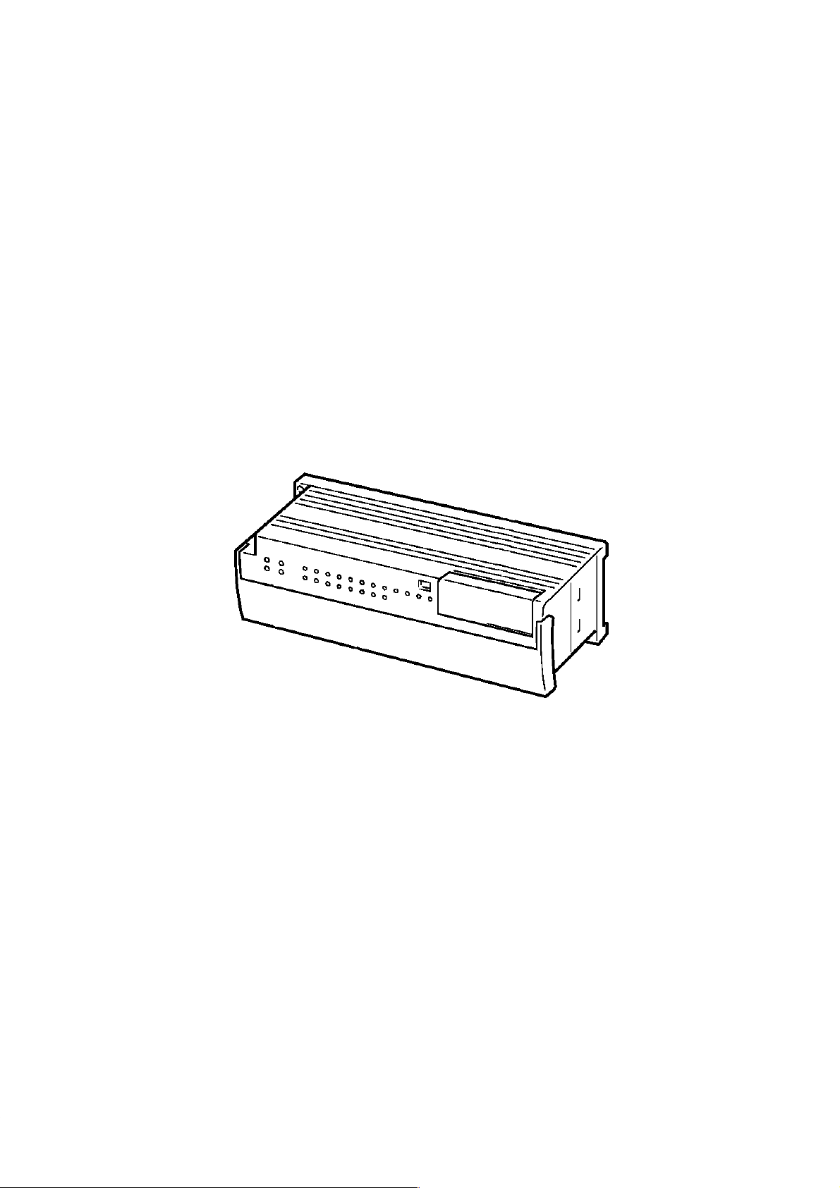
The SK20 is shown below. Two models are available. Both are powered by a
24-VDC power supply. Refer to Appendix A Standard Models for details.
Description and Function of SK20 Parts
Indicators
Switches
Terminal BlocK
5
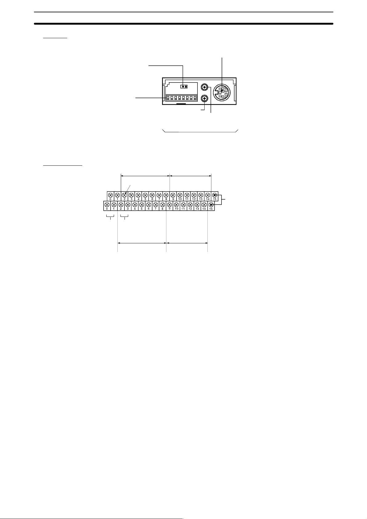
Units Section 1-3
Switches
Terminal Block
End Station Sliding Switch
Set end station when using
SYSMAC BUS. Refer to
1-4-1 Basic Configuration
for details.
DIP Switches
When using SYSMAC
BUS, set switches SW1 to
SW5 to allocate the remote I/O addresses. Refer
to 1-4-1 Basic Configura-
tion for details.
Input terminal
Power
terminals
24 VDC
+ – C0 C1 02 04 06 08 10 C0 02 03 C2 06 07 +
NC NC 00 01 03 05 07 09 11 00 101 C1 04 05 C3 –
NC terminals High-speed Counter
(Wd 00)
High-speed Counter COM
input termianls
00: counter input
01: hardware reset
Analog Timer
Trimmer #2
Refer to pages 82 to 84
for details.
Output terminal
(Wd 01)
Programming Console Connector
For connection to the SP10-PRO01-V1
Programming Console.
Analog Timer
Trimmer #1
SYSMAC BUS connector terminal (RS-485)
C0 to C3: COM (common)
The input side COM terminal (C0) can be
used as the COM for normal inputs when the
High-speed Counter is not used.
Input terminal
(Wd 00)
Output terminal
(Wd 01)
Indicators The PC has four indicators on the front panel, PWR, RUN, T/R, and ERR.
The functions of the indicators are presented as follows.
PWR (green): Lit while power is supplied.
RUN (green): Lit when the PC is in RUN mode and operating normally.
T/R (orange): Flashes during SYSMAC BUS communications. Lit when
an error occurs.
ERR (red): Lit when self-diagnosis detects an error.
Operation Mode on Start-up The SK20 operation mode on start-up is determined by mode setting and
whether the Programming Console is connected.
• If Programming Console is not connected:
RUN mode is automatically selected
• If Programming Console is connected:
Mode selector switch set to RUN: Run mode
Mode selector switch set to PRGM: Program mode
RUN Mode
• RUN mode: The program is executed.
• Program mode: Program execution is halted for to create or edit program.
6

Units Section 1-3
1-3-2 Programming Console
The Programming Console is shown below.
Display
Memory card access indicator
Connecting
cable connector
The Programming Console is used to write and transfer programs to the PC.
It is also used to monitor operation and modify data. The Programming Console can be connected directly to the PC for single PCs. It can also be connected to other Units via a SYSMAC BUS Remote I/O Unit to access each
PC individually without re-connection.
1-3-3 Memory Cards
The Programming Console provides the ability to backup programs. The
Memory Card slot located at the base of the keyboard allows programs to be
transferred directly to and from the Programming Console. Each Card has a
built-in battery to preserve data.
Only one model of Memory Card, HMC-ES141, may be used. Each Memory
Card has 16 Kbytes of S-RAM. One Memory Card can hold up to 18 SK20
programs.
Mode switch
Key pad
Memory card slot
A battery is built-in to the Memory Card to allow the data to be retained. The
battery must be replaced within five years to ensure data is not lost. To remove the battery, insert a sharp object, like a pen tip, into the hole at the bottom right of the card. The new battery must be inserted within one minute of
removing the old one.
Memory Cards have a write-protect switch. When the switch is ON, writing
operations to the memory card will not be possible.
Caution While the Memory Card is being accessed, the M/C ON LED on the Pro-
gramming Console will be lit. If the Memory Card is removed out from the
Programming Console while the LED is ON, the data contained in memory
on the Card may be damaged.
7
PC Configuration Section 1-4
1-4 PC Configuration
All SK20 models provide 20 I/O points (12 input and 8 output points).
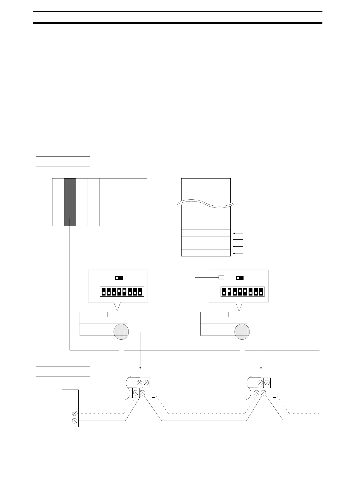
1-4-1 Basic Configuration (SK20-C1DR-D/SK20-C1DT-D)
The diagram below shows an example of a system with four SK20 units connected to one SYSMAC C200H Remote I/O Master Unit. This system functions with SK20-C1DR-D/SK20-C1DT-D units (with SYSMAC BUS function)
only.
Note When starting up the system, turn on the SK20 slave unit power supplies be-
fore turning on the C200H master unit power supply.
System Configuration
Master Unit (RM)
SK20 (relay
station 1)
Remote I/O address allocation
Wd 200
C200H
Wd 224
Wd 226
Wd 228
Wd 230
Address setting: Wd 24 Address setting: Wd 26
End station
setting slide
switch
ON
OFF
SK20 (relay
station 2)
1 3456782
ON
OFF
OFF ON
1 3456782
Relay station 1
Relay station 2
Relay station 3
End station
OFF ON
SYSMAC BUS wiring
Master unit
RS-485
8
14 15
+
SYSMAC BUS
(RS-485)
–
14 15
+
–
The connecting cables should be made of the recommended
cable (VCTF0.75 x 2C).
14 15
14 15
+
SYSMAC BUS
(RS-485)
–
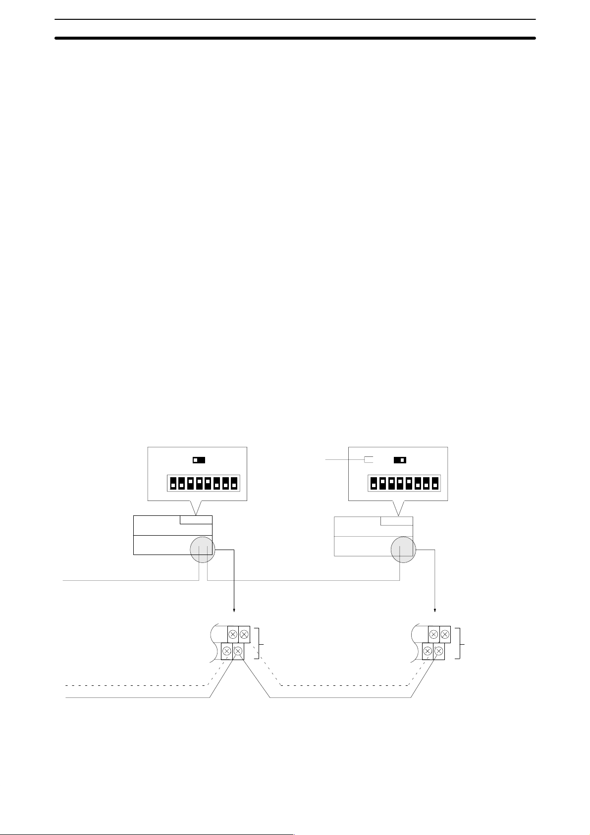
PC Configuration Section 1-4
Set address: 28
ON
OFF
SK20 (relay
station 3)
OFF ON
1 3456782
14 15
14 15
Set address: 30
Set as end station
End station
sliding switch
Turn this switch ON on
the final SYSMAC
BUS unit. It this switch
is not ON, normal operation is not possible.
SK20 (end
station)
SYSMAC BUS
+
SYSMAC BUS
(RS-485)
–
Total cable length not to exceed 200 m.
ON
OFF
OFF ON
1 3456782
14 15
14 15
+
SYSMAC BUS
(RS-485)
–
9
PC Configuration Section 1-4
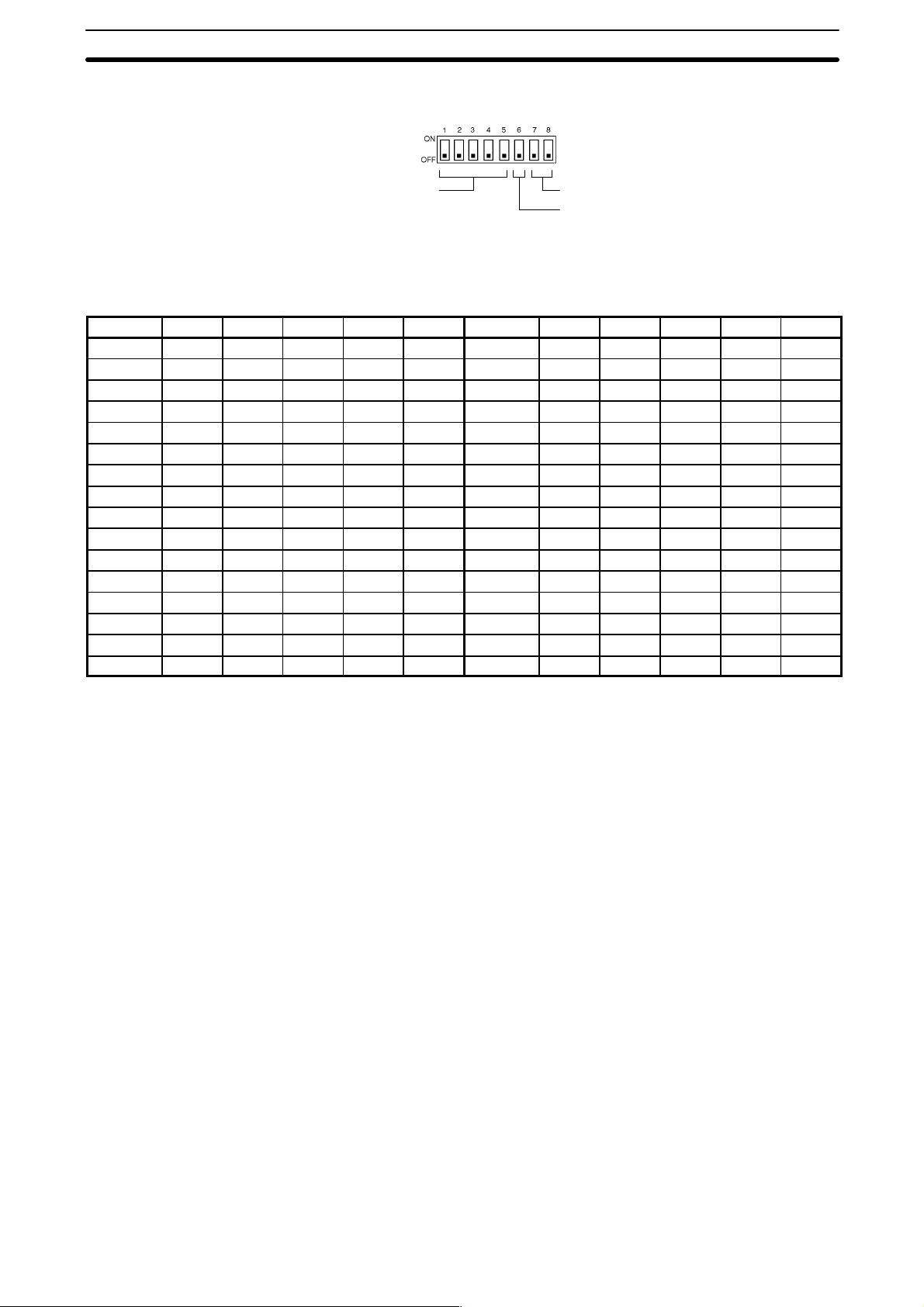
1-4-2 DIP Switch Settings
When using SYSMAC BUS, set switches
SW1 to SW5 to allocate the remote I/O addresses.
Set from 0 to 30. (Set hexadecimal values
between 0 and 1E with SW5 as the mostsignificant bit.)
Leave OFF
On a transfer error clear all
data received from the SYSMAC BUS Master Unit.
ON: Clear all data
OFF: Hold status before error
Address Allocation Settings
Word SW1 SW2 SW3 SW4 SW5 Word SW1 SW2 SW3 SW4 SW5
0 0 0 0 0 0 16 0 0 0 0 1
1 1 0 0 0 0 17 1 0 0 0 1
2 0 1 0 0 0 18 0 1 0 0 1
3 1 1 0 0 0 19 1 1 0 0 1
4 0 0 1 0 0 20 0 0 1 0 1
5 1 0 1 0 0 21 1 0 1 0 1
6 0 1 1 0 0 22 0 1 1 0 1
7 1 1 1 0 0 23 1 1 1 0 1
8 0 0 0 1 0 24 0 0 0 1 1
9 1 0 0 1 0 25 1 0 0 1 1
10 0 1 0 1 0 26 0 1 0 1 1
11 1 1 0 1 0 27 1 1 0 1 1
12 0 0 1 1 0 28 0 0 1 1 1
13 1 0 1 1 0 29 1 0 1 1 1
14 0 1 1 1 0 30 0 1 1 1 1
15 1 1 1 1 0 --- --- --- --- --- ---
0: OFF, 1: ON
Note SK20 uses two words for SYSMAC BUS communications: one for inputs and
one for outputs. Therefore, if address 30 is set, words 30 and 31 are allocated to SYSMAC BUS I/O. When allocating data to consecutive words, use
only even-numbered or odd-numbered words.
10

SECTION 2
Installation
This section provides information on mounting and wiring the CPUs and on I/O specifications. Basic unit connections
are described in 1-4 PC Configuration. Detailed specifications are provided in Appendix B Specifications.
2-1 Dimensions 12. . . . . . . . . . . . . . . . . . . . . . . . . . . . . . . . . . . . . . . . . . . . . . . . . . . . . . . . . . . . . .
2-2 Installation 14. . . . . . . . . . . . . . . . . . . . . . . . . . . . . . . . . . . . . . . . . . . . . . . . . . . . . . . . . . . . . .
2-2-1 Installation Environment 14. . . . . . . . . . . . . . . . . . . . . . . . . . . . . . . . . . . . . . . . . . . .
2-2-2 Cooling 14. . . . . . . . . . . . . . . . . . . . . . . . . . . . . . . . . . . . . . . . . . . . . . . . . . . . . . . . . .
2-2-3 Preventing Noise 15. . . . . . . . . . . . . . . . . . . . . . . . . . . . . . . . . . . . . . . . . . . . . . . . . .
2-2-4 Mounting Requirements 15. . . . . . . . . . . . . . . . . . . . . . . . . . . . . . . . . . . . . . . . . . . .
2-3 Wiring 16. . . . . . . . . . . . . . . . . . . . . . . . . . . . . . . . . . . . . . . . . . . . . . . . . . . . . . . . . . . . . . . . . .
2-3-1 Power Supply 17. . . . . . . . . . . . . . . . . . . . . . . . . . . . . . . . . . . . . . . . . . . . . . . . . . . . .
2-3-2 I/O Connections 17. . . . . . . . . . . . . . . . . . . . . . . . . . . . . . . . . . . . . . . . . . . . . . . . . . .
2-3-3 Precautions 18. . . . . . . . . . . . . . . . . . . . . . . . . . . . . . . . . . . . . . . . . . . . . . . . . . . . . . .
2-4 Programming Console 19. . . . . . . . . . . . . . . . . . . . . . . . . . . . . . . . . . . . . . . . . . . . . . . . . . . . .
2-4-1 Input Filters 19. . . . . . . . . . . . . . . . . . . . . . . . . . . . . . . . . . . . . . . . . . . . . . . . . . . . . .
11
Dimensions Section 2-1
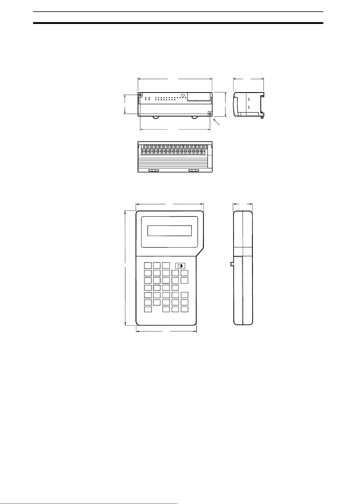
2-1 Dimensions
This section gives mounting dimensions. All dimensions are in millimeters.
CPUs
Programming Console
SK20
40
SP10-PRO01-V1
160
50
150
91
Two M4 screws,
4.5 dia.
65
25
155
81
12
Dimensions Section 2-1
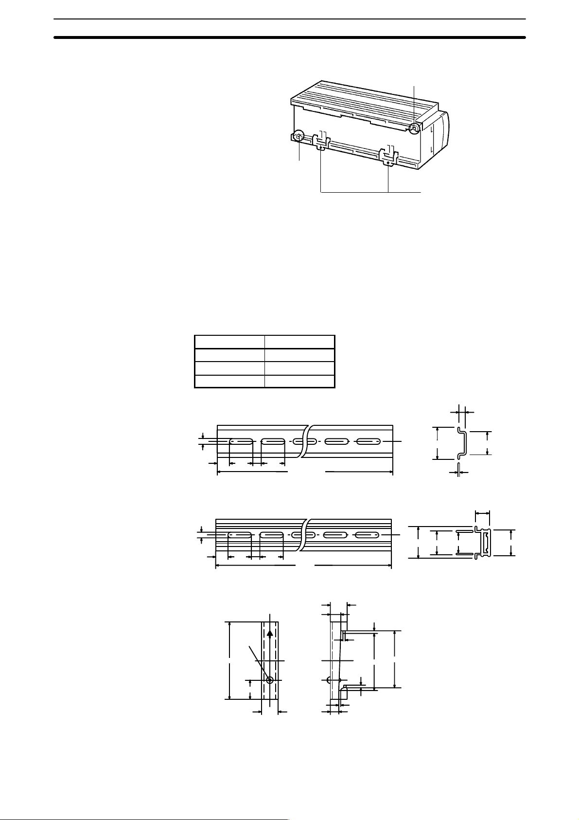
Surface Mounting Dimensions
Panel mounting M4 screw hole
Panel mounting M4 screw hole
DIN Track fixing lug
Note Install the SK20 such that the heat radiation from top of the unit is not re-
stricted.
Leave the plastic seal on the top surface of the unit in place during installation and wiring to prevent dust and foreign matter from entering the unit. The
plastic seal must be removed after installation and wiring are complete. If it is
not removed after the Unit is installed, the plastic seal will cause the Unit to
overheat during operation.
Mounting Track
The SK20 can be mounted onto DIN Tracks.
Model No. Length (L)
PFP-50N 50 cm
PFP-100N 1 m
PFP-100N2 1 m
PFP-50N/PFP-100N
4.5
25 25
15
10
PFP-100N2
4.5
25 25
15
10
End Plate (PFP-M)
1000 (500) *
1000
7.3±0.15
35±0.3 27±0.5
1
16
27 24
35±0.3
10
6.2
1.8
29.2
4.8
1.3
1
1.8
35.5
35.3
M4x8
50
11.5
10
13

Installation Section 2-2
2-2 Installation
2-2-1 Installation Environment
Although the SK20 Programmable Controllers are highly reliable and durable, a number of factors should be considered when installing them. Do not
expose an SK20 to the following conditions.
• An ambient temperature that falls below 0 or exceeds 55 °C for the CPU, or
that falls below 0 or exceeds 45 °C for the Programming Console.
• Abrupt changes in temperature that cause condensation.
• A relative humidity less than 10% or greater than 90%.
• Corrosive or flammable gas.
• Dust, salt, or iron particles.
• Direct vibration or shock.
• Direct sunlight.
• Water, oil, or chemicals.
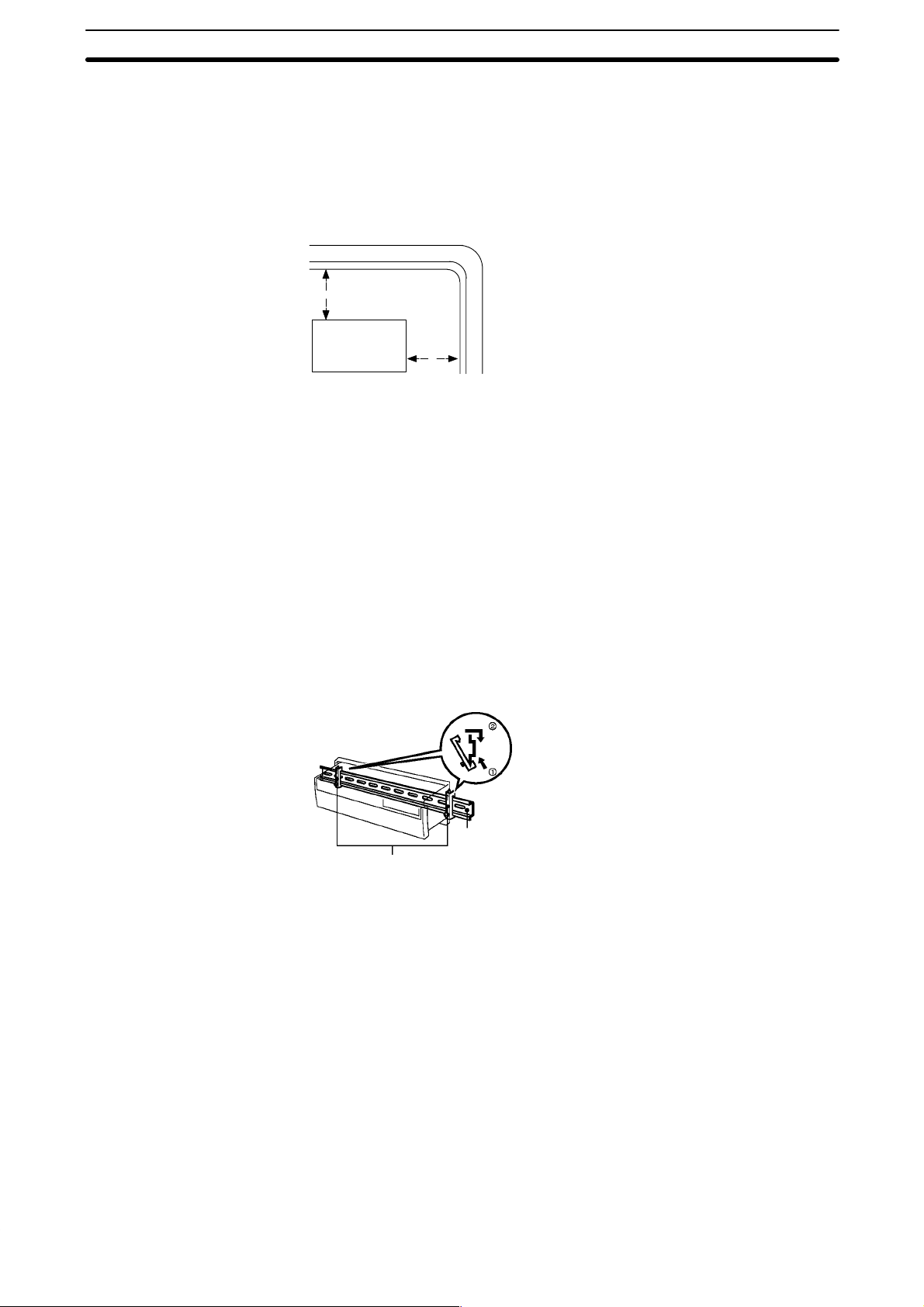
2-2-2 Cooling
There are two points to consider in order to ensure that the PC does not
overheat. The first is the clearance between the CPUs and control panel surround them, and the second is the installation of a cooling fan.
Clearance The CPUs need to have sufficient room between them to allow for I/O wiring,
and additional room to ensure that the wiring does not hamper cooling. The
CPU’s must be mounted close enough so that the length of the Connecting
Cable does not exceed 4 meters.
Cooling Fan Ensure adequate ventilation is provided for the PCs. A cooling fan is not al-
ways necessary, but may be needed if the PC is mounted in a warm or enclosed area or over a source of heat. Although it is best to avoid installing the
PC in a warm area, use a cooling fan or an air conditioner, as shown in the
following illustration, to maintain the ambient temperature within specifications.
Control Panel
Fan
14
PC
Louver
Installation Section 2-2
2-2-3 Preventing Noise
In order to prevent noise from interfering with the operation of the PC, use
AWG 14 twisted-pair cables (cross-sectional area of at least 2 mm
mount the PC in a control panel in which high-power equipment is installed
and make sure the point of installation is at least 200 mm away from power
cables, as shown in the following diagram. Ground the panel to which the PC
is mounted.
Power lines
200 mm min.
PC
200 mm min.
Whenever possible, use wiring conduit to hold the I/O wiring. Standard wiring
conduit should be used, and it should be long enough to completely contain
the I/O wiring and keep it separated from other cables.
2-2-4 Mounting Requirements
The system consists of from one to four CPUs. The Units may be mounted
horizontally or vertically, as desired. Do not mount a Unit on its side. The Unit
should be mounted with the printing on the front panel oriented as it would
normally be read. The PC can be mounted using DIN Track or mounted directly to any sturdy support meeting the environmental specifications listed in
Appendix B Specifications.
2
). Do not
Track Mounting The PC may be mounted on a DIN Track if desired. Use 35 mm-wide DIN
track to mount the Unit. Two end plates are required to fix the SK20 in place.
PFP-50N
PFP-M End Plates
PFP-100N
PFP-100N2
DIN Track
15
Wiring Section 2-3
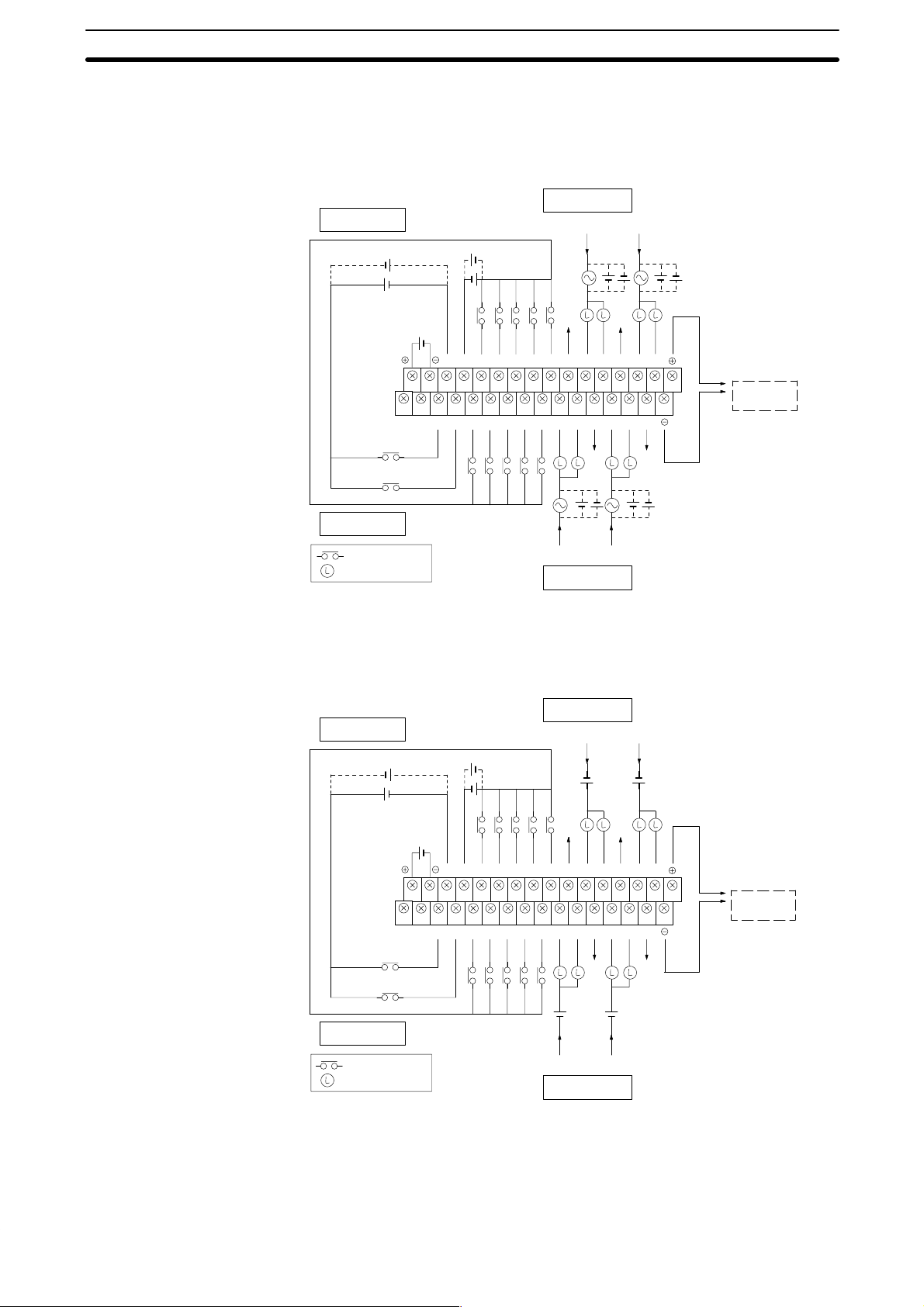
2-3 Wiring
Power and I/O wiring connections are required. Supply 24 VDC power with
sufficient capacity and low ripple.
Relay Contact Output Model
Output circuit (Word 01)
Input circuit (Word 00)
24 VDC
24-VDC
power supply
24 VDC
C1 C3
250 VAC or
24 VDC max.
Caution Do not wire the terminal marked “NC.”
Transistor Output Model
0 1C02C13024045066087108C0902100311C21206130714
0
1 2 3 4 5 6 7 8 9 10 11 12 13 141515
NC 00 01 03 05 07 09 11 00 01 C1 04 05 C3
NC
High-speed
counter input
Hard reset input
Input circuit (Word 00)
: Input contact
: Load
Input circuit (Word 00)
24 VDC
24-VDC
power supply
24 VDC
SYSMAC
BUS
(RS-485)
250 VAC or
24 VDC max.
C2C0
Output circuit (Word 01)
Output circuit (Word 01)
C1 C3
24 VDC
16
0 1C02C13024045066087108C0902100311C21206130714
0
1 2 3 4 5 6 7 8 9 10 11 12 13 141515
NC 00 01 03 05 07 09 11 00 01 C1 04 05 C3
NC
High-speed
counter input
Hard reset input
Input circuit (Word 00)
: Input contact
: Load
Output circuit (Word 01)
Caution Do not wire the terminal marked “NC.”
SYSMAC
BUS
(RS-485)
24 VDC
C2C0
Wiring Section 2-3
2-3-1 Power Supply
Use independent power sources for the inputs, the output loads, and the PC.
Voltage fluctuations caused by current surges to motors may affect operation
of the PC. When using more than one PC, use a separate power supply for
each PC, firstly to prevent voltage drops caused by surge currents and secondly, to prevent the breaker from malfunctioning.
The following diagrams show the proper way to connect the power source to
the PC. Refer to Appendix B Specifications for detailed specifications.
DC Connections Supply 24 VDC and keep voltage fluctuations within the specified range.
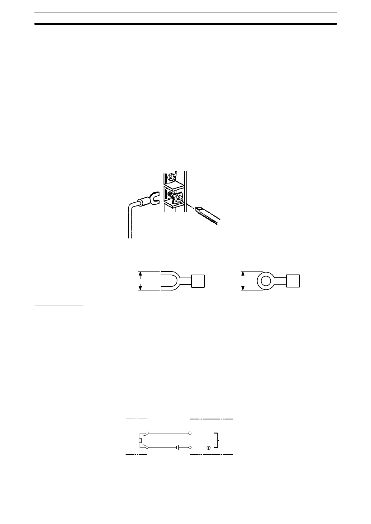
2-3-2 I/O Connections
Connect the I/O devices to the I/O terminals using wire with a cross-sectional
area of 1.04 to 2.63 mm
self-rising pressure plates. Connect the lead wires to the terminals as shown
below. Tighten the screws with a torque of 8 kg-cm maximum.
2
. The terminals have screws with M3.5 heads and
If you wish to attach solderless type terminals to the ends of the lead wires,
use terminals having the following dimensions.
7.5 mm max.7.5 mm max.
Input Circuits
Either positive or negative poles of the power supply can be connected to the
common (COM) terminals, enabling connection of both PNP (negative common) and NPN (positive common) inputs.
The input circuit consumes about 6 mA (typ. at 24 VDC) per input point.
DC Input Examples The following diagrams show the correct way to wire the terminals on the
CPU. When wiring, work carefully to ensure that all terminals are wired correctly. If an input device is connected to an output point, damage may result.
Check all I/O devices to ensure they meet the specifications (refer to Appen-
dix B Specifications).
The DC inputs in the following diagrams are NPN (positive common). Reverse the polarity if PNP (negative common) is used.
DC Input Devices
SK20
DC input
6 mA
IN
COM
24 VDC
17
Wiring Section 2-3
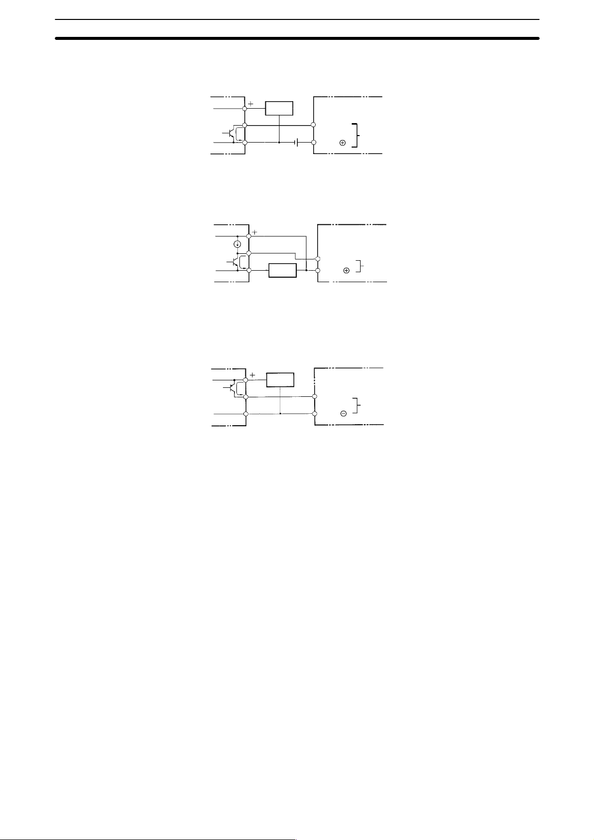
NPN Open-collector Outputs
Sensor
power
supply
NPN Current Outputs
PNP Current Outputs
Current
regulator
Output
6 mA
0 V
Output
6 mA
0 V
Output
6 mA
0 V
Sensor
power
supply
Sensor
power
supply
IN
COM
Use the same power supply
for the input and sensor.
IN
COM
IN
COM
SK20
DC input
SK20
DC input
SK20
DC input
2-3-3 Precautions
Unit Sticker A sticker is provided on the upper face of the CPU to prevent foreign objects,
such as wire clippings, from entering the CPU. Leave this protective sticker
on until the CPU is ready for operation. The sticker must be removed before
operation to enable proper cooling.
Contact Outputs High inductance on for contact outputs will reduce relay life. Keep inductance
low and use an arc suppressor (such as a diode for DC loads). This is particular important with inductive DC loads.
Vibration Relay operation may be adversely affected if the relay is located near contac-
tors, valves, motors, or other devices that produce vibration.
Protective Circuits We recommend the use of arc suppressors to increase contact life and allevi-
ate the affects of noise. Arc suppressors, however, will delay release time
somewhat and, if used incorrectly, they can inhibit proper operation. The
most common arc suppressors for AC are capacitor-resistor circuits and varistor circuits; for DC: capacitor-resistor circuits, diode circuits, and varistor
circuit. Do not use a capacitor without a resistor as the charging current flow
to the capacitor when current is turned ON can cause the contacts to fuse.
18

Programming Console Section 2-4
2-4 Programming Console
Connect the Programmable Console to the SK20 with the connecting cable.
The cable can be connected or removed any time the Programmable Console is not communicating.
Type of Cable
SP10-PRO01-V1
Connecting Cable Use one of the following Connecting Cables to connect the Programming Console.
2-4-1 Input Filters
External input
Input detection time
SP10-CN221 (2 m)
SP10-CN421 (4 m)
To prevent the PC from malfunctioning due to the chattering (bouncing) of the
input device signals or induced noise, the input signals are received via a
filter. The filter may be adjusted so that input pulses of a duration less than a
minimum specified duration of the filter are ignored. The minimum duration
before the detection of an input signal may be set to 0, 1, 5, or 10 ms. The
following diagram illustrates the use of a filter.
tt
The input detection time, t, for the various possible settings is given in the
following table. The “key” column shows which key is pressed to input each
setting in the key sequence below.
Key Setting Actual detection time
0 0 ms t = 150 µs
1 1 ms t = 1 to 1.5 ms
2 5 ms t = 5 to 5.5 ms
3 10 ms t = 10 to 10.5 ms
During the period t to t + 0.5 ms, the positive and negative transitions of the
input signal may or may not be detected.
19
Programming Console Section 2-4
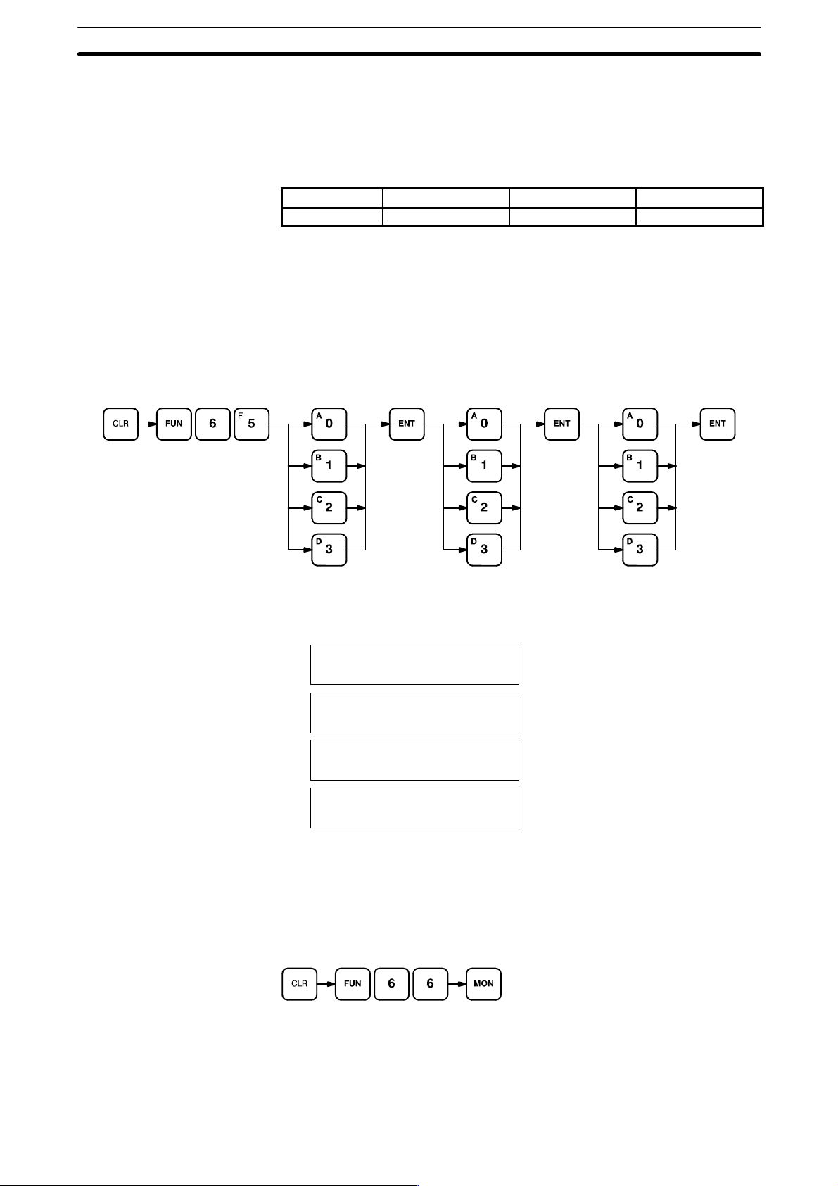
Filter Value Settings
Key Sequence
The filter values are set using the Programming Console. The input circuits
are grouped into three groups. The circuits included in each group depend on
the PC, as shown in the table below. A different filter value can be set for
each group. The filter values can be set in PROGRAM mode only and must
be set before operating the PC. The filter values are set simultaneously in the
PC and in the Programming Console.
PC model Group 1 inputs Group 2 inputs Group 3 inputs
SK20 0 and 1 2 to 9 10 and 1 1
Always set the filter values after transferring the program and before starting
operation. Set the filter value to 5 or 10 ms when the PC is installed in environments subject to noise, or when input devices that may cause chattering
are connected to the PC. If the filter value is set to 0 or 1 ms, be sure that the
input wiring is carefully installed to prevent interference.
Input 0 to specify 0 ms, 1 for 1 ms, 2 for 5 ms, and 3 for 10 ms.
Group 1 Group 2
Group 3
ABC
D
Key Sequence
The following diagrams illustrate the Programming Console displays at the
respective positions marked in the key sequence diagram.
0 FILTER VAL SETGROUP1 SE
A
T NO.?
0 FILTER VAL SET
B
GROUP2 SET NO.?
0 FILTER VAL SET
C
GROUP3 SET NO.?
0 FILTER VAL OK
D
Set the filter values of groups 1, 2, and 3 at the same time. After entering the
filter values, read them on the Programming Console for confirmation. Use
the following key sequence. Reading is possible in either RUN or PROGRAM
mode.
20
The Programming Console will display the information in the following format.

Programming Console Section 2-4
SP10-PRO01-V1
The display will show the settings for groups 1, 2, and 3 when the programming console is connected to an SK20.
0 PC :0–1–2
ProCo:0–2–2
PC settings
Group 1: 0 ms; group 2: 1 ms; group 3: 5 ms.
Programming Console settings
Group 1: 0 ms; group 2: 5 ms; group 3: 5 ms.
21

SECTION 3
Programming
This section takes you all the way through the programming procedure from understanding memory area allocation to
debugging and executing the program. Section 4 Operation will then provide procedures for monitoring PC operation
and manipulating data after you have written, input, and debugged the program.
3-1 Introduction 25. . . . . . . . . . . . . . . . . . . . . . . . . . . . . . . . . . . . . . . . . . . . . . . . . . . . . . . . . . . . .
3-2 Memory Areas 25. . . . . . . . . . . . . . . . . . . . . . . . . . . . . . . . . . . . . . . . . . . . . . . . . . . . . . . . . . .
3-2-1 Data Area Structure 26. . . . . . . . . . . . . . . . . . . . . . . . . . . . . . . . . . . . . . . . . . . . . . . .
3-2-2 I/O Bits 28. . . . . . . . . . . . . . . . . . . . . . . . . . . . . . . . . . . . . . . . . . . . . . . . . . . . . . . . . .
3-2-3 Work Bits 28. . . . . . . . . . . . . . . . . . . . . . . . . . . . . . . . . . . . . . . . . . . . . . . . . . . . . . . .
3-2-4 Dedicated Bits 28. . . . . . . . . . . . . . . . . . . . . . . . . . . . . . . . . . . . . . . . . . . . . . . . . . . .
3-2-5 DR Area 31. . . . . . . . . . . . . . . . . . . . . . . . . . . . . . . . . . . . . . . . . . . . . . . . . . . . . . . . .
3-2-6 TC (Timer/Counter) Area 31. . . . . . . . . . . . . . . . . . . . . . . . . . . . . . . . . . . . . . . . . . .
3-3 The Programming Console 32. . . . . . . . . . . . . . . . . . . . . . . . . . . . . . . . . . . . . . . . . . . . . . . . .
3-3-1 The Keyboard 32. . . . . . . . . . . . . . . . . . . . . . . . . . . . . . . . . . . . . . . . . . . . . . . . . . . .
3-3-2 PC Modes 33. . . . . . . . . . . . . . . . . . . . . . . . . . . . . . . . . . . . . . . . . . . . . . . . . . . . . . . .
3-4 Basic Programming 34. . . . . . . . . . . . . . . . . . . . . . . . . . . . . . . . . . . . . . . . . . . . . . . . . . . . . . .
3-4-1 Terminology 34. . . . . . . . . . . . . . . . . . . . . . . . . . . . . . . . . . . . . . . . . . . . . . . . . . . . . .
3-4-2 Mnemonic Code 35. . . . . . . . . . . . . . . . . . . . . . . . . . . . . . . . . . . . . . . . . . . . . . . . . . .
3-4-3 Ladder Instructions 36. . . . . . . . . . . . . . . . . . . . . . . . . . . . . . . . . . . . . . . . . . . . . . . .
3-4-4 OUTPUT and OUTPUT NOT 38. . . . . . . . . . . . . . . . . . . . . . . . . . . . . . . . . . . . . . . .
3-4-5 The END Instruction 39. . . . . . . . . . . . . . . . . . . . . . . . . . . . . . . . . . . . . . . . . . . . . . .
3-4-6 Logic Block Instructions 39. . . . . . . . . . . . . . . . . . . . . . . . . . . . . . . . . . . . . . . . . . . .
3-4-7 Coding Multiple Right-hand Instructions 45. . . . . . . . . . . . . . . . . . . . . . . . . . . . . . .
3-5 Inputting the Program 45. . . . . . . . . . . . . . . . . . . . . . . . . . . . . . . . . . . . . . . . . . . . . . . . . . . . .
3-5-1 Initial Programming Console Operation 46. . . . . . . . . . . . . . . . . . . . . . . . . . . . . . . .
3-5-2 Clearing Memory 47. . . . . . . . . . . . . . . . . . . . . . . . . . . . . . . . . . . . . . . . . . . . . . . . . .
3-5-3 Clearing Error Messages 48. . . . . . . . . . . . . . . . . . . . . . . . . . . . . . . . . . . . . . . . . . . .
3-5-4 Setting and Reading from Program Memory Address 48. . . . . . . . . . . . . . . . . . . . .
3-5-5 Entering or Editing Programs 49. . . . . . . . . . . . . . . . . . . . . . . . . . . . . . . . . . . . . . . .
3-5-6 Checking the Program 51. . . . . . . . . . . . . . . . . . . . . . . . . . . . . . . . . . . . . . . . . . . . . .
3-5-7 Program Transfer 52. . . . . . . . . . . . . . . . . . . . . . . . . . . . . . . . . . . . . . . . . . . . . . . . . .
3-5-8 Program Searches 55. . . . . . . . . . . . . . . . . . . . . . . . . . . . . . . . . . . . . . . . . . . . . . . . .
3-5-9 Inserting and Deleting Instructions 55. . . . . . . . . . . . . . . . . . . . . . . . . . . . . . . . . . . .
3-6 Advanced Programming 58. . . . . . . . . . . . . . . . . . . . . . . . . . . . . . . . . . . . . . . . . . . . . . . . . . . .
3-6-1 Interlocks 58. . . . . . . . . . . . . . . . . . . . . . . . . . . . . . . . . . . . . . . . . . . . . . . . . . . . . . . .
3-6-2 Controlling Bit Status 60. . . . . . . . . . . . . . . . . . . . . . . . . . . . . . . . . . . . . . . . . . . . . .
3-6-3 DIFFERENTIATE UP and DIFFERENTIATE DOWN 60. . . . . . . . . . . . . . . . . . . .
3-6-4 KEEP 60. . . . . . . . . . . . . . . . . . . . . . . . . . . . . . . . . . . . . . . . . . . . . . . . . . . . . . . . . . .
3-6-5 Self-maintaining Bits (Seal) 61. . . . . . . . . . . . . . . . . . . . . . . . . . . . . . . . . . . . . . . . .
3-6-6 Work Bits (Internal Relays) 61. . . . . . . . . . . . . . . . . . . . . . . . . . . . . . . . . . . . . . . . . .
3-6-7 Programming Precautions 63. . . . . . . . . . . . . . . . . . . . . . . . . . . . . . . . . . . . . . . . . . .
3-7 Instruction Set 65. . . . . . . . . . . . . . . . . . . . . . . . . . . . . . . . . . . . . . . . . . . . . . . . . . . . . . . . . . .
3-7-1 Notation 65. . . . . . . . . . . . . . . . . . . . . . . . . . . . . . . . . . . . . . . . . . . . . . . . . . . . . . . . .
3-7-2 Instruction Format 65. . . . . . . . . . . . . . . . . . . . . . . . . . . . . . . . . . . . . . . . . . . . . . . . .
3-7-3 Data Areas, Definer Values, and Flags 65. . . . . . . . . . . . . . . . . . . . . . . . . . . . . . . . .
3-7-4 Coding Right-hand Instructions 66. . . . . . . . . . . . . . . . . . . . . . . . . . . . . . . . . . . . . . .
3-7-5 LOAD, LOAD NOT, AND, AND NOT, OR, and OR NOT 68. . . . . . . . . . . . . . . . .
3-7-6 AND LOAD and OR LOAD 69. . . . . . . . . . . . . . . . . . . . . . . . . . . . . . . . . . . . . . . . .
3-7-7 OUTPUT and OUTPUT NOT - OUT and OUT NOT 70. . . . . . . . . . . . . . . . . . . . .
23

3-7-8 DIFFERENTIATE UP and DIFFERENTIA TE DOWN -
3-7-9 KEEP - KEEP(12) 72. . . . . . . . . . . . . . . . . . . . . . . . . . . . . . . . . . . . . . . . . . . . . . . . .
3-7-10 INTERLOCK and INTERLOCK CLEAR - IL(02) and ILC(03) 74. . . . . . . . . . . . .
3-7-11 END - END(01) 76. . . . . . . . . . . . . . . . . . . . . . . . . . . . . . . . . . . . . . . . . . . . . . . . . . .
3-7-12 NO OPERATION - NOP(00) 76. . . . . . . . . . . . . . . . . . . . . . . . . . . . . . . . . . . . . . . .
3-7-13 Timers and Counters 76. . . . . . . . . . . . . . . . . . . . . . . . . . . . . . . . . . . . . . . . . . . . . . .
3-7-14 TIMER - TIM 77. . . . . . . . . . . . . . . . . . . . . . . . . . . . . . . . . . . . . . . . . . . . . . . . . . . .
3-7-15 TIMER - TIMM(20) 81. . . . . . . . . . . . . . . . . . . . . . . . . . . . . . . . . . . . . . . . . . . . . . .
3-7-16 HIGH-SPEED TIMER - TIMH(21) 82. . . . . . . . . . . . . . . . . . . . . . . . . . . . . . . . . . .
3-7-17 ANALOG TIMER - ATIM(22) 82. . . . . . . . . . . . . . . . . . . . . . . . . . . . . . . . . . . . . . .
3-7-18 ANALOG TIMER 1 and 2 - ATM1(25) and ATM2(26) 83. . . . . . . . . . . . . . . . . . . .
3-7-19 COUNTER - CNT 84. . . . . . . . . . . . . . . . . . . . . . . . . . . . . . . . . . . . . . . . . . . . . . . . .
3-7-20 REVERSIBLE DRUM COUNTER -RDM(23) 88. . . . . . . . . . . . . . . . . . . . . . . . . .
3-7-21 HIGH-SPEED COUNTER - CNTH(24) 89. . . . . . . . . . . . . . . . . . . . . . . . . . . . . . . .
3-7-22 SHIFT REGISTER - SFT(33) 91. . . . . . . . . . . . . . . . . . . . . . . . . . . . . . . . . . . . . . . .
3-7-23 MOVE - MOV(30) 93. . . . . . . . . . . . . . . . . . . . . . . . . . . . . . . . . . . . . . . . . . . . . . . .
3-7-24 MOVE NOT - MVN(31) 94. . . . . . . . . . . . . . . . . . . . . . . . . . . . . . . . . . . . . . . . . . . .
3-7-25 COMPARE - CMP(32) 94. . . . . . . . . . . . . . . . . . . . . . . . . . . . . . . . . . . . . . . . . . . . .
3-7-26 BLOCK COMPARE - BCMP(34) 96. . . . . . . . . . . . . . . . . . . . . . . . . . . . . . . . . . . . .
3-7-27 CLEAR CARRY - CLC(44) 98. . . . . . . . . . . . . . . . . . . . . . . . . . . . . . . . . . . . . . . . .
3-7-28 BCD ADD - ADD(40) 98. . . . . . . . . . . . . . . . . . . . . . . . . . . . . . . . . . . . . . . . . . . . . .
3-7-29 BCD SUBTRACT - SUB(41) 99. . . . . . . . . . . . . . . . . . . . . . . . . . . . . . . . . . . . . . . .
3-7-30 AND WORD- ANDW(42) 101. . . . . . . . . . . . . . . . . . . . . . . . . . . . . . . . . . . . . . . . . .
3-7-31 OR WORD - ORW(43) 101. . . . . . . . . . . . . . . . . . . . . . . . . . . . . . . . . . . . . . . . . . . . .
3-7-32 STEP DEFINE and STEP START-STEP(04)/SNXT(05) 102. . . . . . . . . . . . . . . . . . .
3-8 Debugging 106. . . . . . . . . . . . . . . . . . . . . . . . . . . . . . . . . . . . . . . . . . . . . . . . . . . . . . . . . . . . . .
3-8-1 Displaying and Clearing Error Messages 106. . . . . . . . . . . . . . . . . . . . . . . . . . . . . . .
3-8-2 Reading the Cycle Time 107. . . . . . . . . . . . . . . . . . . . . . . . . . . . . . . . . . . . . . . . . . . . .
3-9 Program Execution 108. . . . . . . . . . . . . . . . . . . . . . . . . . . . . . . . . . . . . . . . . . . . . . . . . . . . . . . .
3-9-1 Cycle 108. . . . . . . . . . . . . . . . . . . . . . . . . . . . . . . . . . . . . . . . . . . . . . . . . . . . . . . . . . .
3-10 I/O Response Time 109. . . . . . . . . . . . . . . . . . . . . . . . . . . . . . . . . . . . . . . . . . . . . . . . . . . . . . . .
3-10-1 Single PCs 109. . . . . . . . . . . . . . . . . . . . . . . . . . . . . . . . . . . . . . . . . . . . . . . . . . . . . . .
3-10-2 Operation and Cycle Time at Power ON 111. . . . . . . . . . . . . . . . . . . . . . . . . . . . . . . .
3-10-3 I/O Response Time 112. . . . . . . . . . . . . . . . . . . . . . . . . . . . . . . . . . . . . . . . . . . . . . . .
3-11 Using SK20 SYSMAC BUS Functions 113. . . . . . . . . . . . . . . . . . . . . . . . . . . . . . . . . . . . . . . .
3-11-1 I/O Response Time 113. . . . . . . . . . . . . . . . . . . . . . . . . . . . . . . . . . . . . . . . . . . . . . . .
DIFU(10) and DIFD(11) 70. . . . . . . . . . . . . . . . . . . . . . . . . . . . . . . . . . . . . . . . . . . .
24

Memory Areas Section 3-2
3-1 Introduction
There are several basic steps involved in writing a program. Sheets that can
be copied to aid in programming are provided in Appendix F I/O Assignment
Sheets and Appendix G Program Coding Sheet.
1, 2, 3.. Obtain a list of all I/O devices and the I/O points that have been as-
signed to them and prepare a table that shows the I/O bit allocated to
each I/O device.
Determine what words are available for work bits and prepare a table in
which you can allocate these as you use them.
Also prepare tables of TC numbers so that you can allocate these as
you use them. Remember, the function of a TC number can be defined
only once within the program. (TC numbers are described in 3-7-13 Tim-
ers and Counters.)
Draw the ladder diagram.
Input the program into the Programming Console.
Check the program for syntax errors and correct these.
Transfer the program from the Programming Console to the CPU and
execute the program to check for execution errors and correct these.
After the entire Control System has been installed and is ready for use,
execute the program and fine tune it if required.
3-2 Memory Areas
Details, including the name, acronym, range, and function of each area are
summarized in the following table. All but the last area are data areas. Data
and memory areas are normally referred to by their acronyms. Bits not listed
in the following table cannot be used.
Area
Input bits 12 00 0000 to 0011 Input external signals to the PC. These bits can be used as
Output bits 8 01 0100 to 0107 Each of these bits can be used in only one instruction
Work bits 172 00 0012 to 0015 These bits are used within the program to aid programming.
SYSMAC BUS
communications
bits
Dedicated bits 112 03 to 09 0300 to 0915 These bits are assigned specific functions. For details, refer to
Data Retention
(DR)
Timer/Counter
(TC)
No. of
bits
32* 19 1900 to 1915 SK20 to Master transmitted data
256
max.
16 TIM/CNT 00 to 15 Used to define timers and counters and to access Completion
Word
addresses
01 0108 to 0115
02 0200 to 0215
10 to 18 1000 to 1815
20 2000 to 2015 Master to SK20 received data
DR 00 to
DR 15
Bit
addresses
DR 0000 to
DR 1515
Function
many times as required in the program.
controlling its status, but can be used as many times as
required in other instructions. If the status of the same output
bit is controlled by more than one instruction, only the status
determined by the last instruction will be output.
the table in 3-2-4 Dedicated Bits.
These bits retain their ON/OFF state even during power
interruptions.
Flags, PV, and SV for them. TC 11 and TC12 are used by the
instructions ANALOG TIMER1 (ATM1) and ANALOG TIMER2
(ATM2) respectively. TC 14 is used by the HIGH-SPEED
TIMER instruction (TIMH), and TC 15 is used by the ANALOG
TIMER instruction.
*Note The SYSMAC BUS communications bits (words 19 and 20) are available in
the SK20-C1DR-D/SK20-C1DT-D only. These bits are work bits in the
SK20-C2DR-D/SK20-C2DT-D.
25
Memory Areas Section 3-2
3-2-1 Data Area Structure
When designating a data area, the acronym for the area is always required
for the DR, and TC areas.
An actual data within any data area but the TC area is designated by its address. The address designates the bit or word within the area where the desired data is located. The TC area consists of TC numbers, each of which is
used for a specific timer or counter defined in the program. Refer to 3-2-6 TC
(Timer/Counter) Area for more details on TC numbers.
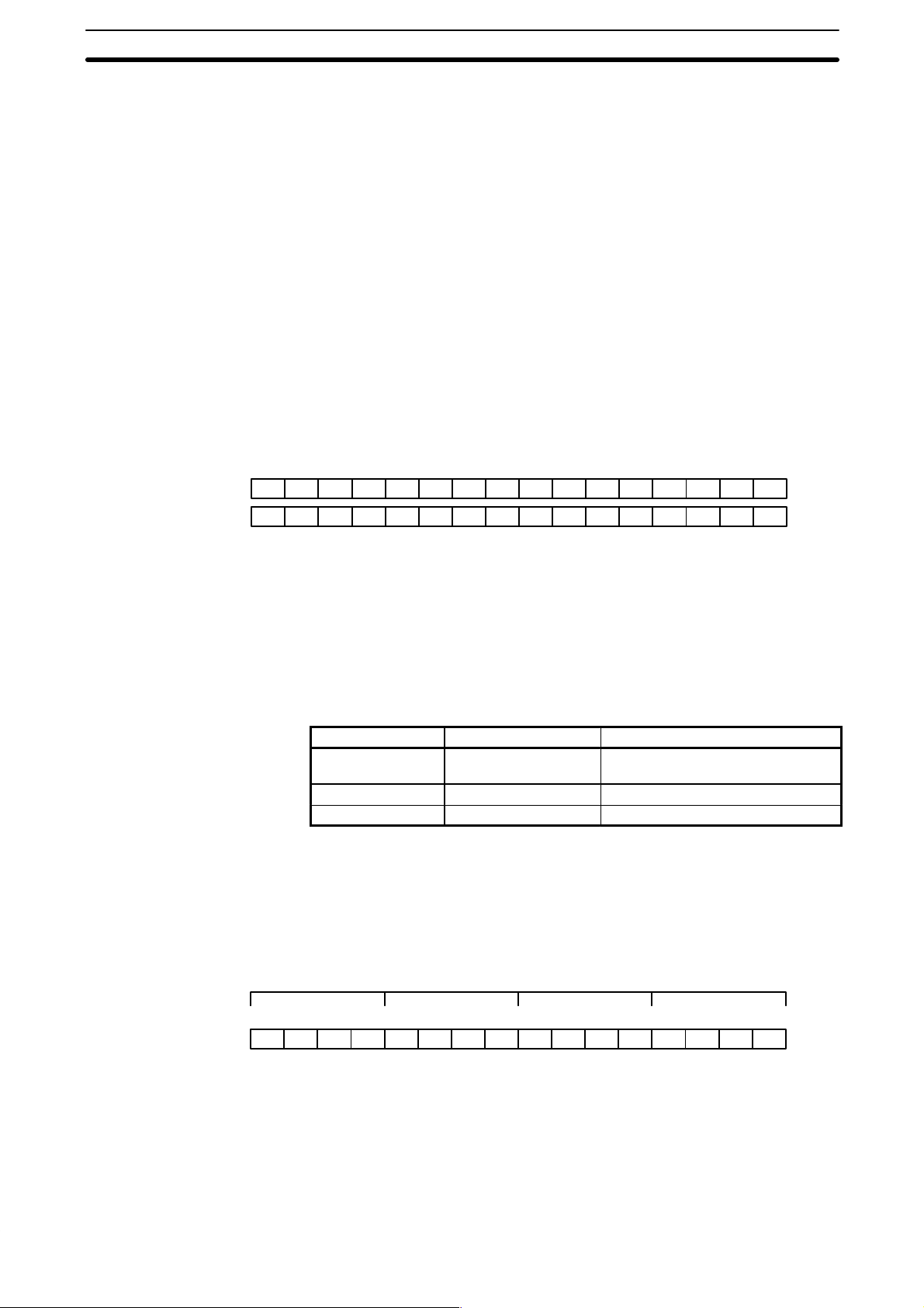
The rest of the data area consists of words, each of which consists of 16 bits
numbered 00 through 15 from right to left. Words 000 and 001 are shown
below with bit numbers. Here, the content of each word is shown as all zeros.
Bit 00 is called the rightmost bit; bit 15, the leftmost bit.
The term least significant bit is often used for rightmost bit; the term most
significant bit, for leftmost bit. These terms are not used in this manual because a single data word is often split into two or more parts, with each part
used for different parameters or operands. When this is done, the rightmost
bits of a word may actually become the most significant bits, i.e., the leftmost
bits in another word, when combined with other bits to form a new word.
Bit number
Word 000 0000000000000000
Word 001 0000000000000000
Data Structure
15 14 13 12 11 10 09 08 07 06 05 04 03 02 01 00
To designate data by word, all that is necessary is the acronym (if required)
and the two-digit word address. To designate data by bit, the word address is
combined with the bit number as a single four-digit address. The following
table show examples of this. The two rightmost digits of a bit designation
must indicate a bit between 00 and 15, i.e., the rightmost digit must be 5 or
less the next digit to the left, either 0 or 1.
The same TC number can be used to designate either the present value (PV)
of the timer or counter, or a bit that functions as the Completion flag for the
timer or counter.
Area Word designation Bit designation
I/O, work, and
dedicated bits
TC TC 03 (designates PV) TC 03 (designates Completion Flag)
DR DR 15 DR 0513
00 0015 (leftmost bit in word 00)
Word data input as decimal values is stored in binary-coded decimal (BCD);
word data entered as hexadecimal is stored in binary form. Each four bits of
a word represents one digit, either a hexadecimal or decimal digit, numerically equivalent to the value of the binary bits. One word of data thus contains
four digits, which are numbered from right to left. These digit numbers and
the corresponding bit numbers for one word are shown below.
26
Digit number 3210
Bit number
Contents 0000000000000000
15 14 13 12 11 10 09 08 07 06 05 04 03 02 01 00
When referring to the entire word, the digit numbered 0 is called the rightmost digit; the one numbered 3, the leftmost digit.
When inputting data into data areas, it must be input in the proper form for
the intended purpose. This is no problem when designating individual bits,

Memory Areas Section 3-2
which are merely turned ON (equivalent to a binary value of 1) or OFF (a
binary value of 0). When inputting word data, however, it is important to input
it either as decimal or as hexadecimal, depending on what is called for by the
instruction it is to be used for. 3-7 Instruction Set specifies when a particular
form of data is required for an instruction.
Converting Different Forms
of Data
Decimal Points
Binary and hexadecimal can be easily converted back and forth because
each four bits of a binary number is numerically equivalent to one digit of a
hexadecimal number. The binary number 0101111101011111 is converted to
hexadecimal by considering each set of four bits in order from the right.
Binary 1111 is hexadecimal F; binary 0101 is hexadecimal 5. The hexadeci-
3
mal equivalent would thus be 5F5F, or 24,415 in decimal (16
x 5 + 162 x 15
+ 16 x 5 + 15).
Decimal and BCD are easily converted back and forth. In this case, each
BCD digit (i.e., each group of four BCD bits) is numerically equivalent of the
corresponding decimal digit. The BCD bits 0101011101010111 are converted
to decimal by considering each four bits from the right. Binary 0101 is decimal 5; binary 0111 is decimal 7. The decimal equivalent would thus be 5,757.
Note that this is not the same numeric value as the hexadecimal equivalent
of 0101011101010111, which would be 5,757 hexadecimal, or 22,359 in deci-
3
mal (16
x 5 + 162 x 7 + 16 x 5 + 7).
Because the numeric equivalent of each four BCD binary bits must be numerically equivalent to a decimal value, any four bit combination numerically
greater then 9 cannot be used, e.g., 1011 is not allowed because it is numerically equivalent to 11, which cannot be expressed as a single digit in decimal
notation. The binary bits 1011 are of course allowed in hexadecimal are a
equivalent to the hexadecimal digit C.
Decimal points are used in timers only. The least significant digit represents
tenths of a second. All arithmetic instructions operate on integers only.
Indirect Addressing
Normally, when the content of a data area word is specified for an instruction,
the instruction is performed directly on the content of that word. For example,
suppose CMP(32) (COMPARE), with word 05 as the first operand and DR 10
as the second operand, is used in the program. When this instruction is executed, the content of word 05 is compared with that of DR 10.
It is also possible, however, to use indirect DR addresses as operands for
instructions. If *DR 01 is specified as the data for a programming instruction,
the asterisk in front of DR indicates that it is an indirect address that specifies
another DR word which contains the actual operand data. If, in this case, the
content of DR 01 is 06, then *DR 01 indicates DR 06 as the word that contains the desired data, and the content of DR 06 is used as the operand in
the instruction. The following example shows this type of indirect addressing
with the MOVE instruction (MOV(30)).
MOV(30)
*DR 01
DR 00
Indirect
address
Word Content
DR 00 4C01
DR 01 0006
DR 02 F693
DR 06 5555
DR 07 21A5
DR 08 D945
Indicates
DR 06.
5555
moved to
DR 00.
27
 Loading...