

Sysmac CQM1 Operation Manual

Cat. No. W226-E1-7
Programmable Controllers
SYSMAC
CQM1
CQM1 Programmable Controllers
Operation Manual
Revised September 2000

!
!
!
ii
Notice:
OMRON products are manufactured for use according to proper procedures by a qualified operator
and only for the purposes described in this manual.
The following conventions are used to indicate and classify precautions in this manual. Always heed
the information provided with them. Failure to heed precautions can result in injury to people or damage to property.
DANGER Indicates an imminently hazardous situation which, if not avoided, will result in death or
serious injury.
WARNING Indicates a potentially hazardous situation which, if not avoided, could result in death or
serious injury.
Caution Indicates a potentially hazardous situation which, if not avoided, may result in minor or
moderate injury, or property damage.
OMRON Product References
All OMRON products are capitalized in this manual. The word “Unit” is also capitalized when it refers
to an OMRON product, regardless of whether or not it appears in the proper name of the product.
The abbreviation “Ch,” which appears in some displays and on some OMRON products, often means
“word” and is abbreviated “Wd” in documentation in this sense.
The abbreviation “PC” means Programmable Controller and is not used as an abbreviation for anything else.
Visual Aids
The following headings appear in the left column of the manual to help you locate different types of
information.
Note Indicates information of particular interest for efficient and convenient operation
of the product.
1, 2, 3...
1. Indicates lists of one sort or another, such as procedures, checklists, etc.
OMRON, 1993
All rights reserved. No part of this publication may be reproduced, stored in a retrieval system, or transmitted, in any
form, or by any means, mechanical, electronic, photocopying, recording, or otherwise, without the prior written permission of OMRON.
No patent liability is assumed with respect to the use of the information contained herein. Moreover, because OMRON is
constantly striving to improve its high-quality products, the information contained in this manual is subject to change
without notice. Every precaution has been taken in the preparation of this manual. Nevertheless, OMRON assumes no
responsibility for errors or omissions. Neither is any liability assumed for damages resulting from the use of the information contained in this publication.

iii
About this Manual:
The CQM1 is a compact, high-speed Programmable Controller (PC) designed for advanced control
operations in systems requiring from 16 to 256 I/O points per PC. There are two manuals describing the
setup and operation of the CQM1: The
CQM1 Operation Manual
(this manual) and the
CQM1 Program-
ming Manual
. Also available is the
CQM1-series Dedicated I/O Units Operation Manual
.
This manual describes the system configuration and installation of the CQM1 and provides an basic
explanation of operating procedures for the Programming Consoles and introduces the capabilities of the
Ladder Support Software (LSS) and SYSMAC Support Software (SSS). Read this manual first to acquaint
yourself with the CQM1.
The
CQM1 Programming Manual
provides detailed descriptions of the CQM1’s programming functions.
The
Ladder Support Software Operation Manual
and the
SYSMAC Support Software Operation Manual:
C-series PCs
provides descriptions of LSS and SSS operations for the CQM1 and C-series PCs. Use
Version-3 LSS or a later version for CQM1 operation.
Please read this manual carefully and be sure you understand the information provide before attempting
to install and operate the CQM1.
Section 1
gives a brief overview of the steps involved in developing of a CQM1 System, describes the
possible system configurations, and describes the CQM1’s special features and functions.
Section 2
describes the Units that go together to create a CQM1 PC and provides information on switch
settings, installation, and hardware maintenance. Technical specifications of the Units are also provided.
Section 3
describes LSS/SSS capabilities, how to connect the Programming Console, and how to per-
form the various Programming Console operations.
Section 4
describes how to diagnose and correct the hardware and software errors that can occur during
PC operation.
The
Appendix
provides tables of CQM1 Units and related products.
WARNING Failure to read and understand the information provided in this manual may result in
personal injury or death, damage to the product, or product failure. Please read each
section in its entirety and be sure you understand the information provided in the section
and related sections before attempting any of the procedures or operations given.
!

v
TABLE OF CONTENTS
PRECAUTIONS vii . . . . . . . . . . . . . . . . . . . . . . . . . . . . . . . . . . . . . . . . . . . . . . . .
1 Intended Audience viii . . . . . . . . . . . . . . . . . . . . . . . . . . . . . . . . . . . . . . . . . . . . . . . .
2 General Precautions viii . . . . . . . . . . . . . . . . . . . . . . . . . . . . . . . . . . . . . . . . . . . . . . .
3 Safety Precautions viii . . . . . . . . . . . . . . . . . . . . . . . . . . . . . . . . . . . . . . . . . . . . . . . .
4 Operating Environment Precautions viii . . . . . . . . . . . . . . . . . . . . . . . . . . . . . . . . . . .
5 Application Precautions ix . . . . . . . . . . . . . . . . . . . . . . . . . . . . . . . . . . . . . . . . . . . .
6 Conformance to EC Directives x . . . . . . . . . . . . . . . . . . . . . . . . . . . . . . . . . . . . . . .
SECTION 1 – Introduction 1 . . . . . . . . . . . . . . . . . . . . . . . . . . . . . . . . . . . . . . .
1-1 Overview 2 . . . . . . . . . . . . . . . . . . . . . . . . . . . . . . . . . . . . . . . . . . . . . . . . . . . . . . . .
1-2 System Configuration 3 . . . . . . . . . . . . . . . . . . . . . . . . . . . . . . . . . . . . . . . . . . . . . .
1-3 CQM1 Features 3 . . . . . . . . . . . . . . . . . . . . . . . . . . . . . . . . . . . . . . . . . . . . . . . . . .
SECTION 2 – Units and Installation 5 . . . . . . . . . . . . . . . . . . . . . . . . . . . . . . .
2-1 CPU Unit 6 . . . . . . . . . . . . . . . . . . . . . . . . . . . . . . . . . . . . . . . . . . . . . . . . . . . . . . . .
2-1-1 CPU Unit Components 7 . . . . . . . . . . . . . . . . . . . . . . . . . . . . . . . . . . . .
2-1-2 DIP Switch 8 . . . . . . . . . . . . . . . . . . . . . . . . . . . . . . . . . . . . . . . . . . . . . .
2-1-3 Indicators 9 . . . . . . . . . . . . . . . . . . . . . . . . . . . . . . . . . . . . . . . . . . . . . . .
2-1-4 PC Modes 10 . . . . . . . . . . . . . . . . . . . . . . . . . . . . . . . . . . . . . . . . . . . . . . .
2-1-5 Dimensions and Weights 11 . . . . . . . . . . . . . . . . . . . . . . . . . . . . . . . . . . .
2-1-6 Memory Cassette 11 . . . . . . . . . . . . . . . . . . . . . . . . . . . . . . . . . . . . . . . . .
2-1-7 Battery Replacement 13 . . . . . . . . . . . . . . . . . . . . . . . . . . . . . . . . . . . . . .
2-1-8 Programmable Controller Power Interruptions 14 . . . . . . . . . . . . . . . . . .
2-1-9 Analog Setting Function 15 . . . . . . . . . . . . . . . . . . . . . . . . . . . . . . . . . . .
2-1-10 Pulse I/O Function 15 . . . . . . . . . . . . . . . . . . . . . . . . . . . . . . . . . . . . . . . .
2-1-11 ABS Interface Function 17 . . . . . . . . . . . . . . . . . . . . . . . . . . . . . . . . . . . .
2-2 Power Supply Unit 18 . . . . . . . . . . . . . . . . . . . . . . . . . . . . . . . . . . . . . . . . . . . . . . . .
2-2-1 Power Supply Unit Components 18 . . . . . . . . . . . . . . . . . . . . . . . . . . . . .
2-2-2 Dimensions 18 . . . . . . . . . . . . . . . . . . . . . . . . . . . . . . . . . . . . . . . . . . . . .
2-2-3 Selecting a Power Supply Unit 18 . . . . . . . . . . . . . . . . . . . . . . . . . . . . . .
2-3 I/O Units 20 . . . . . . . . . . . . . . . . . . . . . . . . . . . . . . . . . . . . . . . . . . . . . . . . . . . . . . . .
2-3-1 Maximum No. of I/O Units and I/O Points 21 . . . . . . . . . . . . . . . . . . . . .
2-3-2 Terminal Block Type 22 . . . . . . . . . . . . . . . . . . . . . . . . . . . . . . . . . . . . . .
2-3-3 Connector Type 22 . . . . . . . . . . . . . . . . . . . . . . . . . . . . . . . . . . . . . . . . . .
2-3-4 CQM1-OC224 Dimensions 23 . . . . . . . . . . . . . . . . . . . . . . . . . . . . . . . . .
2-3-5 Standard Dimensions 23 . . . . . . . . . . . . . . . . . . . . . . . . . . . . . . . . . . . . . .
2-4 PC Assembly and Installation 24 . . . . . . . . . . . . . . . . . . . . . . . . . . . . . . . . . . . . . . . .
2-4-1 Connecting PC Components 24 . . . . . . . . . . . . . . . . . . . . . . . . . . . . . . . .
2-4-2 DIN Track Installation 25 . . . . . . . . . . . . . . . . . . . . . . . . . . . . . . . . . . . . .
2-5 Wiring and Connections 26 . . . . . . . . . . . . . . . . . . . . . . . . . . . . . . . . . . . . . . . . . . . .
2-5-1 AC Power Supply Unit Wiring 26 . . . . . . . . . . . . . . . . . . . . . . . . . . . . . .
2-5-2 DC Power Supply Unit Wiring 27 . . . . . . . . . . . . . . . . . . . . . . . . . . . . . .
2-5-3 Wiring Precautions for Ground Wires 28 . . . . . . . . . . . . . . . . . . . . . . . . .
2-5-4 I/O Unit Wiring 29 . . . . . . . . . . . . . . . . . . . . . . . . . . . . . . . . . . . . . . . . . .
2-5-5 Compliance with EC Directives 33 . . . . . . . . . . . . . . . . . . . . . . . . . . . . .
2-5-6 Cable Preparation (Connector Type) 35 . . . . . . . . . . . . . . . . . . . . . . . . . .
2-5-7 Cable Preparation (Pulse Output and ABS Interface) 36 . . . . . . . . . . . . .
2-5-8 Peripheral Port Connection 37 . . . . . . . . . . . . . . . . . . . . . . . . . . . . . . . . .
2-5-9 RS-232C Port 38 . . . . . . . . . . . . . . . . . . . . . . . . . . . . . . . . . . . . . . . . . . . .

Table of contents
vi
2-6 Unit Specifications 40 . . . . . . . . . . . . . . . . . . . . . . . . . . . . . . . . . . . . . . . . . . . . . . . .
2-6-1 Power Supply Units 40 . . . . . . . . . . . . . . . . . . . . . . . . . . . . . . . . . . . . . . .
2-6-2 CPU Unit Specifications 40 . . . . . . . . . . . . . . . . . . . . . . . . . . . . . . . . . . .
2-6-3 Pulse Input Port (CQM1-CPU43-EV1) 42 . . . . . . . . . . . . . . . . . . . . . . . .
2-6-4 ABS Interface Port (CQM1-CPU44-EV1) 48 . . . . . . . . . . . . . . . . . . . . .
2-6-5 24-VDC Inputs (Built into CPU Unit) 51 . . . . . . . . . . . . . . . . . . . . . . . . .
2-6-6 12-VDC Input Units 53 . . . . . . . . . . . . . . . . . . . . . . . . . . . . . . . . . . . . . . .
2-6-7 12 to 24-VDC and 24-VDC Input Units 55 . . . . . . . . . . . . . . . . . . . . . . .
2-6-8 24-VDC Input Units 56 . . . . . . . . . . . . . . . . . . . . . . . . . . . . . . . . . . . . . . .
2-6-9 AC Input Units 58 . . . . . . . . . . . . . . . . . . . . . . . . . . . . . . . . . . . . . . . . . . .
2-6-10 Contact Output Units 59 . . . . . . . . . . . . . . . . . . . . . . . . . . . . . . . . . . . . . .
2-6-11 Transistor Output Units 61 . . . . . . . . . . . . . . . . . . . . . . . . . . . . . . . . . . . .
SECTION 3 – The LSS, SSS, SYSMAC-CPT, and Programming Consoles 73
3-1 LSS Capabilities 74 . . . . . . . . . . . . . . . . . . . . . . . . . . . . . . . . . . . . . . . . . . . . . . . . . .
3-1-1 Offline Operations 74 . . . . . . . . . . . . . . . . . . . . . . . . . . . . . . . . . . . . . . . .
3-1-2 Online Operations 75 . . . . . . . . . . . . . . . . . . . . . . . . . . . . . . . . . . . . . . . .
3-1-3 Offline and Online Operations 75 . . . . . . . . . . . . . . . . . . . . . . . . . . . . . . .
3-2 SSS Capabilities 75 . . . . . . . . . . . . . . . . . . . . . . . . . . . . . . . . . . . . . . . . . . . . . . . . . .
3-2-1 Offline Operations 76 . . . . . . . . . . . . . . . . . . . . . . . . . . . . . . . . . . . . . . . .
3-2-2 Online Operations 79 . . . . . . . . . . . . . . . . . . . . . . . . . . . . . . . . . . . . . . . .
3-2-3 Offline and Online Operations 82 . . . . . . . . . . . . . . . . . . . . . . . . . . . . . . .
3-3 SYSMAC-CPT Precautions 82 . . . . . . . . . . . . . . . . . . . . . . . . . . . . . . . . . . . . . . . . .
3-3-1 I/O Table Display 82 . . . . . . . . . . . . . . . . . . . . . . . . . . . . . . . . . . . . . . . . .
3-3-2 Inputting Ladder Diagrams 83 . . . . . . . . . . . . . . . . . . . . . . . . . . . . . . . . .
3-4 Compatible Programming Consoles 83 . . . . . . . . . . . . . . . . . . . . . . . . . . . . . . . . . . .
3-5 Preparation for Operation 84 . . . . . . . . . . . . . . . . . . . . . . . . . . . . . . . . . . . . . . . . . . .
3-6 Programming Console Operations 86 . . . . . . . . . . . . . . . . . . . . . . . . . . . . . . . . . . . .
3-6-1 Designating Operands 86 . . . . . . . . . . . . . . . . . . . . . . . . . . . . . . . . . . . . .
3-6-2 Clearing Memory 87 . . . . . . . . . . . . . . . . . . . . . . . . . . . . . . . . . . . . . . . . .
3-6-3 Reading/Clearing Error Messages 88 . . . . . . . . . . . . . . . . . . . . . . . . . . . .
3-6-4 Buzzer Operation 88 . . . . . . . . . . . . . . . . . . . . . . . . . . . . . . . . . . . . . . . . .
3-6-5 Reading and Changing Expansion Instructions 89 . . . . . . . . . . . . . . . . . .
3-6-6 Reading and Changing the Clock 90 . . . . . . . . . . . . . . . . . . . . . . . . . . . .
3-6-7 Setting and Reading a Program Memory Address 90 . . . . . . . . . . . . . . .
3-6-8 Instruction Search 91 . . . . . . . . . . . . . . . . . . . . . . . . . . . . . . . . . . . . . . . .
3-6-9 Bit Operand Search 91 . . . . . . . . . . . . . . . . . . . . . . . . . . . . . . . . . . . . . . .
3-6-10 Inserting and Deleting Instructions 92 . . . . . . . . . . . . . . . . . . . . . . . . . . .
3-6-11 Entering or Editing Programs 93 . . . . . . . . . . . . . . . . . . . . . . . . . . . . . . .
3-6-12 Checking the Program 96 . . . . . . . . . . . . . . . . . . . . . . . . . . . . . . . . . . . . .
3-6-13 Bit, Digit, Word Monitor 96 . . . . . . . . . . . . . . . . . . . . . . . . . . . . . . . . . . .
3-6-14 Differentiation Monitor 98 . . . . . . . . . . . . . . . . . . . . . . . . . . . . . . . . . . . .
3-6-15 Binary Monitor 99 . . . . . . . . . . . . . . . . . . . . . . . . . . . . . . . . . . . . . . . . . .
3-6-16 3-Word Monitor 99 . . . . . . . . . . . . . . . . . . . . . . . . . . . . . . . . . . . . . . . . . .
3-6-17 Decimal Monitor With Sign 100 . . . . . . . . . . . . . . . . . . . . . . . . . . . . . . . .
3-6-18 Decimal Monitor Without Sign 101 . . . . . . . . . . . . . . . . . . . . . . . . . . . . . .
3-6-19 3-Word Data Modification 101 . . . . . . . . . . . . . . . . . . . . . . . . . . . . . . . . . .
3-6-20 Changing Timer, Counter SV 102 . . . . . . . . . . . . . . . . . . . . . . . . . . . . . . .
3-6-21 Hexadecimal, BCD Data Modification 103 . . . . . . . . . . . . . . . . . . . . . . . .
3-6-22 Binary Data Modification 103 . . . . . . . . . . . . . . . . . . . . . . . . . . . . . . . . . .
3-6-23 Decimal Data Modification With Sign 104 . . . . . . . . . . . . . . . . . . . . . . . .
3-6-24 Decimal Data Modification Without Sign 105 . . . . . . . . . . . . . . . . . . . . . .
3-6-25 Force Set, Reset 106 . . . . . . . . . . . . . . . . . . . . . . . . . . . . . . . . . . . . . . . . . .
3-6-26 Clear Force Set/Reset 107 . . . . . . . . . . . . . . . . . . . . . . . . . . . . . . . . . . . . .
3-6-27 Hex-ASCII Display Change 107 . . . . . . . . . . . . . . . . . . . . . . . . . . . . . . . .
3-6-28 Displaying the Cycle Time 108 . . . . . . . . . . . . . . . . . . . . . . . . . . . . . . . . .
3-6-29 Inputting Signed Binary Data Using Decimal Values 108 . . . . . . . . . . . . .
3-6-30 Using Signed Binary Instructions 110 . . . . . . . . . . . . . . . . . . . . . . . . . . . .

Table of contents
vii
SECTION 4 – Troubleshooting 111 . . . . . . . . . . . . . . . . . . . . . . . . . . . . . . . . . . . .
4-1 Introduction 112 . . . . . . . . . . . . . . . . . . . . . . . . . . . . . . . . . . . . . . . . . . . . . . . . . . . . . .
4-2 Programming Console Operation Errors 113 . . . . . . . . . . . . . . . . . . . . . . . . . . . . . . .
4-3 Programming Errors 113 . . . . . . . . . . . . . . . . . . . . . . . . . . . . . . . . . . . . . . . . . . . . . . .
4-4 User-defined Errors 114 . . . . . . . . . . . . . . . . . . . . . . . . . . . . . . . . . . . . . . . . . . . . . . . .
4-5 Operating Errors 115 . . . . . . . . . . . . . . . . . . . . . . . . . . . . . . . . . . . . . . . . . . . . . . . . . .
4-5-1 Non-fatal Errors 115 . . . . . . . . . . . . . . . . . . . . . . . . . . . . . . . . . . . . . . . . . .
4-5-2 Fatal Errors 116 . . . . . . . . . . . . . . . . . . . . . . . . . . . . . . . . . . . . . . . . . . . . .
4-6 Troubleshooting Flowcharts 117 . . . . . . . . . . . . . . . . . . . . . . . . . . . . . . . . . . . . . . . . .
Appendix 125 . . . . . . . . . . . . . . . . . . . . . . . . . . . . . . . . . . . . . . . . . . . . . . . . . . . . . .
A – Standard Models 125 . . . . . . . . . . . . . . . . . . . . . . . . . . . . . . . . . . . . . . . . . . . . . . . . . . . .
B – Battery Service Life 129 . . . . . . . . . . . . . . . . . . . . . . . . . . . . . . . . . . . . . . . . . . . . . . . . .
C – SYSMAC-CPT Precautions 131 . . . . . . . . . . . . . . . . . . . . . . . . . . . . . . . . . . . . . . . . . . .
Glossary 133 . . . . . . . . . . . . . . . . . . . . . . . . . . . . . . . . . . . . . . . . . . . . . . . . . . . . . . .
Index 149 . . . . . . . . . . . . . . . . . . . . . . . . . . . . . . . . . . . . . . . . . . . . . . . . . . . . . . . . .

ix
PRECAUTIONS
This section provides general precautions for using the Programmable Controller (PC) and related devices.
The information contained in this section is important for the safe and reliable application of the Programmable Controller. You must read this section and understand the information contained before attempting to set up or operate a
PC system.
1 Intended Audience viii . . . . . . . . . . . . . . . . . . . . . . . . . . . . . . . . . . . . . . . . . . . . . . . . .
2 General Precautions viii . . . . . . . . . . . . . . . . . . . . . . . . . . . . . . . . . . . . . . . . . . . . . . . .
3 Safety Precautions viii . . . . . . . . . . . . . . . . . . . . . . . . . . . . . . . . . . . . . . . . . . . . . . . . .
4 Operating Environment Precautions viii . . . . . . . . . . . . . . . . . . . . . . . . . . . . . . . . . . .
5 Application Precautions ix . . . . . . . . . . . . . . . . . . . . . . . . . . . . . . . . . . . . . . . . . . . . .
6 Conformance to EC Directives x . . . . . . . . . . . . . . . . . . . . . . . . . . . . . . . . . . . . . . . .

!
!
!
!
!
!
4Operating Environment Precautions
x
1 Intended Audience
This manual is intended for the following personnel, who must also have knowledge of electrical systems (an electrical engineer or the equivalent).
• Personnel in charge of installing FA systems.
• Personnel in charge of designing FA systems.
• Personnel in charge of managing FA systems and facilities.
2 General Precautions
The user must operate the product according to the performance specifications
described in the operation manuals.
Before using the product under conditions which are not described in the manual
or applying the product to nuclear control systems, railroad systems, aviation
systems, vehicles, combustion systems, medical equipment, amusement
machines, safety equipment, and other systems, machines, and equipment that
may have a serious influence on lives and property if used improperly, consult
your OMRON representative.
Make sure that the ratings and performance characteristics of the product are
sufficient for the systems, machines, and equipment, and be sure to provide the
systems, machines, and equipment with double safety mechanisms.
This manual provides information for programming and operating the Unit. Be
sure to read this manual before attempting to use the Unit and keep this manual
close at hand for reference during operation.
WARNING It is extremely important that a PC and all PC Units be used for the specified
purpose and under the specified conditions, especially in applications that can
directly or indirectly affect human life. You must consult with your OMRON
representative before applying a PC System to the above-mentioned
applications.
3 Safety Precautions
WARNING Do not attempt to take any Unit apart while the power is being supplied. Doing so
may result in electric shock.
WARNING Do not touch any of the terminals while the power is being supplied. Doing so
may result in electric shock.
WARNING Do not attempt to disassemble, repair, or modify any Units. Any attempt to do so
may result in malfunction, fire, or electric shock.
Caution Tighten the screws on the terminal block of the AC Power Supply Unit to the
torque specified in the manual. Loose screws may result in burning or malfunction.
4 Operating Environment Precautions
Caution Do not operate the control system in the following locations:
• Locations subject to direct sunlight.
• Locations subject to temperatures or humidity outside the range specified in
the specifications.

!
!
!
!
5Application Precautions
xi
• Locations subject to condensation as the result of severe changes in temperature.
• Locations subject to corrosive or flammable gases.
• Locations subject to dust (especially iron dust) or salts.
• Locations subject to exposure to water, oil, or chemicals.
• Locations subject to shock or vibration.
Caution Take appropriate and sufficient countermeasures when installing systems in the
following locations:
• Locations subject to static electricity or other forms of noise.
• Locations subject to strong electromagnetic fields.
• Locations subject to possible exposure to radioactivity.
• Locations close to power supplies.
Caution The operating environment of the PC System can have a large effect on the lon-
gevity and reliability of the system. Improper operating environments can lead to
malfunction, failure, and other unforeseeable problems with the PC System. Be
sure that the operating environment is within the specified conditions at installation and remains within the specified conditions during the life of the system.
5 Application Precautions
Observe the following precautions when using the PC System.
WARNING Always heed these precautions. Failure to abide by the following precautions
could lead to serious or possibly fatal injury.
• Always connect to a ground of 100 Ω or less when installing the Units. Not con-
necting to a ground of 100 Ω or less may result in electric shock.
• Always turn OFF the power supply to the PC before attempting any of the following. Not turning OFF the power supply may result in malfunction or electric
shock.
• Mounting or dismounting Power Supply Units, I/O Units, CPU Units,
Memory Cassettes, or any other Units.
• Assembling the Units.
• Setting DIP switches or rotary switches.
• Connecting or wiring the cables.
• Connecting or disconnecting the connectors.
Caution Failure to abide by the following precautions could lead to faulty operation of the
PC or the system, or could damage the PC or PC Units. Always heed these precautions.
• Fail-safe measures must be taken by the customer to ensure safety in the
event of incorrect, missing, or abnormal signals caused by broken signal lines,
momentary power interruptions, or other causes.
• Interlock circuits, limit circuits, and similar safety measures in external circuits
(i.e., not in the Programmable Controller) must be provided by the customer.
• Always use the power supply voltage specified in the manual. An incorrect voltage may result in malfunction or burning.
• Take appropriate measures to ensure that the specified power with the rated
voltage and frequency is supplied. Be particularly careful in places where the
power supply is unstable. An incorrect power supply may result in malfunction.

6Conformance to EC Directives
xii
• Install external breakers and take other safety measures against short-circuiting in external wiring. Insufficient safety measures against short-circuiting may
result in burning.
• Do not apply voltages to the Input Units in excess of the rated input voltage.
Excess voltages may result in burning.
• Do not apply voltages or connect loads to the Output Units in excess of the
maximum switching capacity. Excess voltage or loads may result in burning.
• Disconnect the functional ground terminal when performing withstand voltage
tests. Not disconnecting the functional ground terminal may result in burning.
• Install and wire the Unit properly as specified in the manual. Improper installation of the Unit may result in malfunction.
• Be sure that all the mounting screws, terminal screws, and cable connector
screws are tightened to the torque specified in the relevant manuals. Incorrect
tightening torque may result in malfunction.
• Leave the label attached to the Unit when wiring. Removing the label may
result in malfunction.
• Remove the label after the completion of wiring to ensure proper heat dissipation. Leaving the label attached may result in malfunction.
• Use crimp terminals for wiring. Do not connect bare stranded wires directly to
terminals. Connection of bare stranded wires may result in burning.
• Double-check all the wiring before turning ON the power supply. Incorrect wiring may result in burning.
• Mount the Unit only after checking the terminal block completely.
• Be sure that the terminal blocks, Memory Units, expansion cables, and other
items with locking devices are properly locked into place. Improper locking
may result in malfunction.
• Check the user program for proper execution before actually running it on the
Unit. Not checking the program may result in an unexpected operation.
• Confirm that no adverse ef fect will occur in the system before attempting any of
the following. Not doing so may result in an unexpected operation.
• Changing the operating mode of the PC.
• Force-setting/force-resetting any bit in memory.
• Changing the present value of any word or any set value in memory.
• Do not pull on the cables or bend the cables beyond their natural limit. Doing
either of these may break the cables.
• When replacing parts, be sure to confirm that the rating of a new part is correct.
Not doing so may result in malfunction or burning.
• Before touching a Unit, be sure to first touch a grounded metallic object in order
to discharge any static built-up. Not doing so may result in malfunction or damage.
6 Conformance to EC Directives
The CQM1 PCs comply with EC Directives. To ensure that the machine or
device in which a CQM1 PC is used complies with EC Directives, the PC must be
installed as follows:
1, 2, 3...
1. The PC must be installed within a control panel.
2. Reinforced insulation or double insulation must be used for the DC power
supplies used for the communications and I/O power supplies.
3. PCs complying with EC Directives also conform to the Common Emission
Standard (EN50081-2). When a PC is built into a machine, however, noise
can be generated by switching devices using relay outputs and cause the
6Conformance to EC Directives
xiii
overall machine to fail to meet the Standard. If this occurs, surge killers must
be connected or other measures taken external to the PC.
The following methods represent typical methods for reducing noise, and
may not be sufficient in all cases. Required countermeasures will vary
depending on the devices connected to the control panel, wiring, the configuration of the system, and other conditions.
Determining if Countermeasures Are Required
Refer to EN50081-2 for more details.
Countermeasures are not required if the frequency of load switching for the
whole system including the PC is less than 5 times per minute.
Countermeasures are required if the frequency of load switching for the whole
system including the PC is more than 5 times per minute.
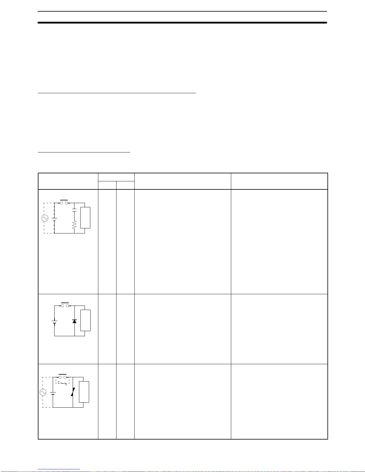
Countermeasure Examples
When switching an inductive load, connect an surge protector, diodes, etc., in
parallel with the load or contact as shown below.
Circuit Current Characteristic Required element
AC DC
CR method
Power
supply
Inductive
load
Yes Yes If the load is a relay or solenoid, there
is a time lag between the moment the
circuit is opened and the moment the
load is reset.
If the supply voltage is 24 or 48 V,
insert the surge protector in parallel
with the load. If the supply voltage is
100 to 200 V, insert the surge
protector between the contacts.
The capacitance of the capacitor must
be 1 to 0.5 µF per contact current of
1 A and resistance of the resistor must
be 0.5 to 1 Ω per contact voltage of
1 V. These values, however, vary with
the load and the characteristics of the
relay. Decide these values from
testing, and take into consideration
that the capacitance suppresses spark
discharge when the contacts are
separated and the resistance limits
the current that flows into the load
when the circuit is closed again.
The dielectric strength of the capacitor
must be 200 to 300 V. If the circuit is
an AC circuit, use a capacitor with no
polarity.
Diode method
Power
supply
Inductive
load
No Yes The diode connected in parallel with
the load changes energy accumulated
by the coil into a current, which then
flows into the coil so that the current
will be converted into Joule heat by
the resistance of the inductive load.
This time lag, between the moment
the circuit is opened and the moment
the load is reset, caused by this
method is longer than that caused by
the CR method.
The reversed dielectric strength value
of the diode must be at least 10 times
as large as the circuit voltage value.
The forward current of the diode must
be the same as or larger than the load
current.
The reversed dielectric strength value
of the diode may be two to three times
larger than the supply voltage if the
surge protector is applied to electronic
circuits with low circuit voltages.
Varistor method
Power
supply
Inductive
load
Yes Yes The varistor method prevents the
imposition of high voltage between the
contacts by using the constant voltage
characteristic of the varistor. There is
time lag between the moment the
circuit is opened and the moment the
load is reset.
If the supply voltage is 24 or 48 V,
insert the varistor in parallel with the
load. If the supply voltage is 100 to
200 V, insert the varistor between the
contacts.
---

6Conformance to EC Directives
xiv
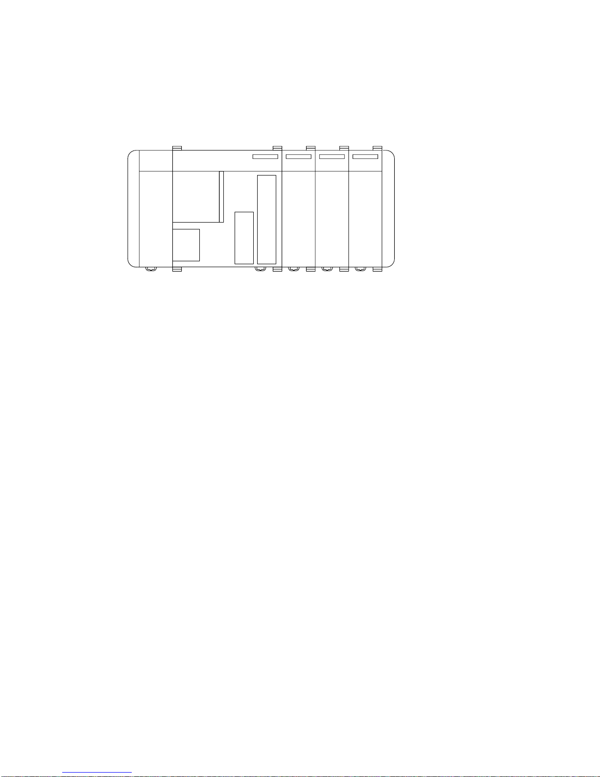
When switching a load with a high inrush current, such as an incandescent lamp,
suppress the inrush current as shown below.
OUT
COM
R
OUT
COM
R
Countermeasure 1
Providing a dark current of approx.
one-third of the rated value
through an incandescent lamp
Countermeasure 2
Providing a limiting resistor

1
SECTION 1
Introduction
This section gives a brief overview of the steps involved in developing of a CQM1 System, describes the possible system
configurations, and describes the CQM1’s special features and functions.
1-1 Overview 2 . . . . . . . . . . . . . . . . . . . . . . . . . . . . . . . . . . . . . . . . . . . . . . . . . . . . . . . .
1-2 System Configuration 3 . . . . . . . . . . . . . . . . . . . . . . . . . . . . . . . . . . . . . . . . . . . . . . .
1-3 CQM1 Features 3 . . . . . . . . . . . . . . . . . . . . . . . . . . . . . . . . . . . . . . . . . . . . . . . . . . .
2
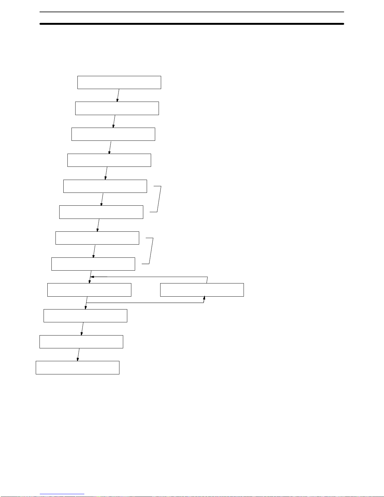
1-1 Overview
The following diagram shows the steps involved in setting up and operating a
CQM1 System and the sections in this and the
CQM1 Programming Manual
that
will be most useful at each step.
Design system.
Create sequence diagram.
Install and wire.
Allocate I/O bits.
Draw ladder diagram.
Code ladder diagram.
Turn on PC.
Input program.
Debug.
Do test run.
Save program.
Run system.
CQM1 Operation Manual
Section 2 Units and Installation
CQM1 Programming Manual
Section 1 PC Setup and Related Features
Section 4 Ladder-diagram Programming
Section 5 Instruction Set
Section 7 CQM1 Operations and Processing Time
CQM1 Operation Manual
Section 3 The LSS, SSS, and Programming Consoles
Ladder Support Software (LSS) Operation Manual
SYSMAC Support Software (SSS) Operation Manual: C-series PCs
CQM1 Operation Manual
Section 3 The LSS, SSS, and Programming Consoles
Ladder Support Software (LSS) Operation Manual
SYSMAC Support Software (SSS) Operation Manual: C-series PCs
CQM1 Programming Manual
Section 7 Troubleshooting
Fix program.
CQM1 Programming Manual
Section 3 Memory Areas
Overview Section 1-1
3
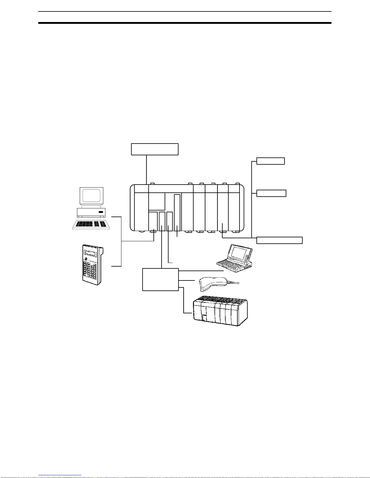
1-2 System Configuration
The CQM1 is a compact, high-speed PC composed of a Power Supply Unit, a
CPU Unit, and I/O Units. All of these Units connect at the sides to form a single
PC, which is normally mounted to a DIN track.
All CQM1 CPU Units, except for the CQM1-CPU11-E, are equipped with an
RS-232C port that can be connected directly to a host computer, another CQM1,
or other serial devices.
The following diagram shows the system configurations possible with the
CQM1. Refer to
Section 2 Hardware Considerations
for more details on system
components and specifications.
IBM PC/AT or
compatible
Dedicated I/O Units
Output Units
DC-input type:
(8/16/32 points)
AC-input type: (8 pts.)
1:1 RS-232C
Host Link
Bar Code Reader
Peripheral
port
Personal computer
CQM1
Programming Console
Ladder Support Software,
SYSMAC Support Software
Power Supply Unit
AC Power Supply Unit (18 W);
AC Power Supply Unit (30 W) with 24-VDC
service power supply;
DC Power Supply Unit (30 W)
Input Units
Contact-output type:
(8 or 16 points)
Transistor-output type:
(8/16/32 points)
B7A Interface Unit,
I/O Link Unit, etc.
High-speed Counter
pulse output
Absolute Encoder
interface
Analog setting
Triac-output type:
(8 points)
1-3 CQM1 Features
Main Features The CQM1 provides many advanced features, including the following:
• The CPU Unit provides 16 built-in input terminals.
• I/O Units can be added to increase I/O capacity.
• The CQM1 is much faster: about 20 times faster than P-type PCs.
• High-speed timers and counters are built in.
• Outputs are processed when instructions are executed (direct outputs).
CQM1 Features
Section 1-3

4
Interrupts The CQM1 supports three types of interrupts:
• Input Interrupts
Input interrupts are used to process input signals from an external device
that are shorter than the program execution time. Input signals with a pulse
width as short as 0.1 ms can be used.
• Scheduled Interrupts
Scheduled interrupts can be performed using a high-speed interval timer.
• High-speed Counter Interrupts
Single-phase pulses up to 5 kHz and two-phase pulses up to 2.5 kHz can be
input. High-speed counter interrupts can be combined with pulse outputs for
applications such as motor control. The CQM1-CPU43-EV1 and
CQM1-CPU44-EV1 can accept single-phase pulses up to 50 kHz and twophase pulses up to 25 kHz. The high-speed counter (absolute encoder input
for the CPU44-EV1) has two points added.
Pulse Output Function Pulses up to 1 kHz can be output from Output Unit contacts. The
CQM1-CPU43-EV1 has two dedicated ports for outputting 50 kHz pulses.
Communications A peripheral port and RS-232C port are available and are used to communicate
with external devices using the following methods.
• Host Link
The CQM1 using the host link can communicate with a personal computer
and Programmable Terminal using host link commands.
• RS-232C
The CQM1 using the RS-232C can read data from a bar code reader or
measurement device and output data to a printer.
• 1-to-1 Link
A data link can be created with a data area in another CQM1 to monitor the
other PC’s status and synchronize processes controlled by the PCs.
Analog Setting Function The CQM1-CPU42-EV1 provides volume controls with four channels for adjust-
ing analog settings.
Convenient I/O Instructions A single instruction can be used to input or output data, simplifying the program.
• The TEN KEY INPUT instruction can be used to read 8-digit BCD data input
from a ten-key.
• The HEXADECIMAL KEY INPUT instruction can be used to read 8-digit hexa-
decimal key input data from I/O Units.
• The DIGITAL SWITCH instruction can be used to read 4 or 8-digit BCD data
from digital switches.
• The 7-SEGMENT DISPLAY OUTPUT instruction can be used to output 4 or
8-digit data to 7-segment displays.
Macros The MACRO instruction can be used to call and execute subroutines, designat-
ing the I/O word for the subroutine as an argument. Using an argument to specify
a subroutine I/O words allows subroutines to be used more easily in different
locations, simplifying the program.
Differentiation Monitoring Up to now, differentiation monitoring was available only in top-of-the-line PCs.
Differentiation monitoring indicates when a bit goes from OFF to ON or from ON
to OFF . It can be used to monitor the status of inputs or bits that turn on and of f in
very short intervals.
CQM1 Features
Section 1-3

5
SECTION 2
Units and Installation
This section describes the Units that go together to create a CQM1 PC and provides information on switch settings, installation, and hardware maintenance. Technical specifications of the Units are also provided.
2-1 CPU Unit 6 . . . . . . . . . . . . . . . . . . . . . . . . . . . . . . . . . . . . . . . . . . . . . . . . . . . . . . . .
2-1-1 CPU Unit Components 7 . . . . . . . . . . . . . . . . . . . . . . . . . . . . . . . . . . . . .
2-1-2 DIP Switch 8 . . . . . . . . . . . . . . . . . . . . . . . . . . . . . . . . . . . . . . . . . . . . . .
2-1-3 Indicators 9 . . . . . . . . . . . . . . . . . . . . . . . . . . . . . . . . . . . . . . . . . . . . . . . .
2-1-4 PC Modes 10 . . . . . . . . . . . . . . . . . . . . . . . . . . . . . . . . . . . . . . . . . . . . . . .
2-1-5 Dimensions and Weights 11 . . . . . . . . . . . . . . . . . . . . . . . . . . . . . . . . . . . .
2-1-6 Memory Cassette 11 . . . . . . . . . . . . . . . . . . . . . . . . . . . . . . . . . . . . . . . . . .
2-1-7 Battery Replacement 13 . . . . . . . . . . . . . . . . . . . . . . . . . . . . . . . . . . . . . . .
2-1-8 Programmable Controller Power Interruptions 14 . . . . . . . . . . . . . . . . . . .
2-1-9 Analog Setting Function 15 . . . . . . . . . . . . . . . . . . . . . . . . . . . . . . . . . . . .
2-1-10 Pulse I/O Function 15 . . . . . . . . . . . . . . . . . . . . . . . . . . . . . . . . . . . . . . . . .
2-1-11 ABS Interface Function 17 . . . . . . . . . . . . . . . . . . . . . . . . . . . . . . . . . . . . .
2-2 Power Supply Unit 18 . . . . . . . . . . . . . . . . . . . . . . . . . . . . . . . . . . . . . . . . . . . . . . . . .
2-2-1 Power Supply Unit Components 18 . . . . . . . . . . . . . . . . . . . . . . . . . . . . . .
2-2-2 Dimensions 18 . . . . . . . . . . . . . . . . . . . . . . . . . . . . . . . . . . . . . . . . . . . . . .
2-2-3 Selecting a Power Supply Unit 18 . . . . . . . . . . . . . . . . . . . . . . . . . . . . . . .
2-3 I/O Units 20 . . . . . . . . . . . . . . . . . . . . . . . . . . . . . . . . . . . . . . . . . . . . . . . . . . . . . . . . .
2-3-1 Maximum No. of I/O Units and I/O Points 21 . . . . . . . . . . . . . . . . . . . . . .
2-3-2 Terminal Block Type 22 . . . . . . . . . . . . . . . . . . . . . . . . . . . . . . . . . . . . . . .
2-3-3 Connector Type 22 . . . . . . . . . . . . . . . . . . . . . . . . . . . . . . . . . . . . . . . . . . .
2-3-4 CQM1-OC224 Dimensions 23 . . . . . . . . . . . . . . . . . . . . . . . . . . . . . . . . . .
2-3-5 Standard Dimensions 23 . . . . . . . . . . . . . . . . . . . . . . . . . . . . . . . . . . . . . . .
2-4 PC Assembly and Installation 24 . . . . . . . . . . . . . . . . . . . . . . . . . . . . . . . . . . . . . . . .
2-4-1 Connecting PC Components 24 . . . . . . . . . . . . . . . . . . . . . . . . . . . . . . . . .
2-4-2 DIN Track Installation 25 . . . . . . . . . . . . . . . . . . . . . . . . . . . . . . . . . . . . . .
2-5 Wiring and Connections 26 . . . . . . . . . . . . . . . . . . . . . . . . . . . . . . . . . . . . . . . . . . . . .
2-5-1 AC Power Supply Unit Wiring 26 . . . . . . . . . . . . . . . . . . . . . . . . . . . . . . .
2-5-2 DC Power Supply Unit Wiring 27 . . . . . . . . . . . . . . . . . . . . . . . . . . . . . . .
2-5-3 Wiring Precautions for Ground Wires 28 . . . . . . . . . . . . . . . . . . . . . . . . . .
2-5-4 I/O Unit Wiring 29 . . . . . . . . . . . . . . . . . . . . . . . . . . . . . . . . . . . . . . . . . . .
2-5-5 Compliance with EC Directives 33 . . . . . . . . . . . . . . . . . . . . . . . . . . . . . .
2-5-6 Cable Preparation (Connector Type) 35 . . . . . . . . . . . . . . . . . . . . . . . . . . .
2-5-7 Cable Preparation (Pulse Output and ABS Interface) 36 . . . . . . . . . . . . . .
2-5-8 Peripheral Port Connection 37 . . . . . . . . . . . . . . . . . . . . . . . . . . . . . . . . . .
2-5-9 RS-232C Port 38 . . . . . . . . . . . . . . . . . . . . . . . . . . . . . . . . . . . . . . . . . . . .
2-6 Unit Specifications 40 . . . . . . . . . . . . . . . . . . . . . . . . . . . . . . . . . . . . . . . . . . . . . . . . .
2-6-1 Power Supply Units 40 . . . . . . . . . . . . . . . . . . . . . . . . . . . . . . . . . . . . . . . .
2-6-2 CPU Unit Specifications 40 . . . . . . . . . . . . . . . . . . . . . . . . . . . . . . . . . . . .
2-6-3 Pulse Input Port (CQM1-CPU43-EV1) 42 . . . . . . . . . . . . . . . . . . . . . . . . .
2-6-4 ABS Interface Port (CQM1-CPU44-EV1) 48 . . . . . . . . . . . . . . . . . . . . . .
2-6-5 24-VDC Inputs (Built into CPU Unit) 51 . . . . . . . . . . . . . . . . . . . . . . . . .
2-6-6 12-VDC Input Units 53 . . . . . . . . . . . . . . . . . . . . . . . . . . . . . . . . . . . . . . .
2-6-7 12 to 24-VDC and 24-VDC Input Units 55 . . . . . . . . . . . . . . . . . . . . . . . .
2-6-8 24-VDC Input Units 56 . . . . . . . . . . . . . . . . . . . . . . . . . . . . . . . . . . . . . . .
2-6-9 AC Input Units 58 . . . . . . . . . . . . . . . . . . . . . . . . . . . . . . . . . . . . . . . . . . .
2-6-10 Contact Output Units 59 . . . . . . . . . . . . . . . . . . . . . . . . . . . . . . . . . . . . . . .
2-6-11 Transistor Output Units 61 . . . . . . . . . . . . . . . . . . . . . . . . . . . . . . . . . . . . .

6
2-1 CPU Unit
The CQM1 is a compact, high-speed PC made up of a CPU Unit, Power Supply
Unit, and I/O Units that together provide up to 256 total I/O points. These components lock together at the sides, allowing simple changes in the size and capacity of the PC. There are six types of CPU Unit, shown in the table below. All of the
CPU Units except for the CQM1-CPU11-E have a built-in RS-232C interface.
Model Maximum
I/O points
Program
capacity
(words)
DM
capacity
(Words)
RS-232C
port
Analog
setting
Pulse
I/O
ABS
interface
AD/DA
conver-
sion
CQM1-CPU11-E
128 pts
3.2K 1K
--- --- --- --- ---
CQM1-CPU21-E
(7 Unit
s
max.)
Yes
--- --- --- ---
CQM1-CPU41-EV1
256 pts
7.2K 6K
--- --- --- ---
CQM1-CPU42-EV1
(11 Units
Yes --- --- ---
CQM1-CPU43-EV1
max.
)
--- Yes --- ---
CQM1-CPU44-EV1 --- --- Yes ---
CQM1-CPU11-E and CQM1-CPU21-E CPU Units provide a maximum of 128
I/O points. The only difference between the two models is the RS-232C port
that is added to the CQM1-CPU21-E.
The CQM1-CPU42-EV1 CPU Unit provides a built-in analog setting function.
It has four dedicated volume controls, and their respective values (0 to 200
BCD) appear in words 220 to 223. This function can be used for operations
such as changing timer and counter set values during operation.
The CQM1-CPU43-EV1 CPU Unit provides a built-in pulse input and output
function. It has two dedicated ports for high-speed counting of up to 25-kHz
two-phase pulse inputs from a device such as a rotary encoder and outputting up to 50-kHz pulses to a device such as a stepping motor.
The CQM1-CPU44-EV1 has two ABS interfaces (absolute encoder interfaces) that can directly receive inputs from absolute-type rotary encoders.
Note In this manual, CQM1-CPU11-E/21-E CPU Units are referred to as “standard
CPU Units,” and CQM1-CPU41-EV1/42-EV1/43-EV1/44-EV1 CPU Units are
referred to as “highly functional, large-capacity CPU Units.”
CQM1-CPU11-E and
CQM1-CPU21-E CPU Units
Built-in Analog Setting
Function
Built-in Pulse I/O Function
Built-in ABS Interface
Function
CPU Unit Section 2-1
7
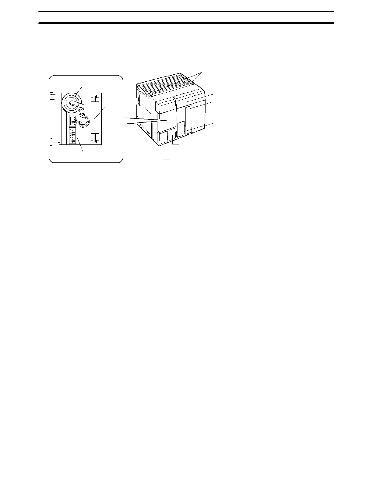
2-1-1 CPU Unit Components
The following diagram shows the basic components of the CPU Unit that are
used in general operation of the PC.
Lock the CPU Unit to
the adjacent Unit.
Indicators
RS-232C Port (except CQM1-CPU11-E)
Used for communications with external devices or other PCs.
Peripheral Port
Used to connect to Peripheral Units such as a Programming Console, Data Access Console, or a computer
running LSS/SSS.
DIP switch
Battery
Memory
cassette
(optional)
Pulse I/O connectors (CQM1-CPU43-EV1 only);
ABS interface connectors (CQM1-CPU44-EV1 only)
Analog setting controls
(CQM1-CPU42-EV1 only)
CPU Unit Section 2-1

8
2-1-2 DIP Switch
The DIP switch is located under a cover on the front of the CPU Unit as shown in
2-1-1 CPU Unit Components
. The setting of these switches is described in the
following table.
Pin Setting Function
1
ON Program Memory and read-only DM (DM 6144 to DM 6655) data
cannot be overwritten from a Peripheral Device.
OFF Program Memory and read-only DM (DM 6144 to DM 6655) data
can be overwritten from a Peripheral Device.
2
ON Auto-boot enabled. The contents of Memory Cassette will be
transferred to the CPU Unit automatically at start-up.
OFF Auto-boot disabled.
3
ON Programming Console messages will be displayed in English.
OFF Programming Console messages will be displayed in the lan-
guage stored in system ROM. (Messages will be displayed in
Japanese with the Japanese version of system ROM.)
4
ON Expansion instructions set by user. Normally ON when using a
host computer for programming/monitoring.
OFF Expansion instructions set to defaults.
5
ON Standard communications parameters (see note 2) will be set for
the following serial communications ports.
• Built-in RS-232C port
• Peripheral port (only when a CQM1-CIF01/-CIF02 Cable is con-
nected. Does not apply to Programming Console.)
Note 1. Standard communications parameters are as follows:
Serial communications mode: Host Link or peripheral
bus; start bits: 1; data length: 7 bits; parity: even; stop
bits: 2; baud rate: 9,600 bps
2. The CX-Programmer running on a personal computer
can be connected to the peripheral port via the peripheral bus using the above standard communications parameters.
OFF The communications parameters for the following serial
communications ports will be set in PC Setup as follows:
• Built-in RS-232C port: DM 6645 and DM 6646
• Peripheral port: DM 6650 and DM 6651
Note When the CX-Programmer is connected to the peripheral
port with the peripheral bus, either set bits 00 to 03 of DM
6650 to 0 Hex (for standard parameters), or set bits 12 to 15
of DM 6650 to 0 Hex and bits 00 to 03 of DM 6650 to 1 Hex
(for Host Link or peripheral bus) separately.
6
ON
The setting of pin 6 determines the ON/OFF status of AR 0712. If
p
p
OFF
pin 6 is ON, AR
0712 will be ON
and if pin 6 is
OFF, AR 0712 will
be OFF. (See note 3.)
Note 1. All DIP switch pins except pin 3 are turned OFF at the factory.
2. The above settings apply to CPU Units manufactured from July 1995 (lot
number jj75 for July 1995). For CPU Units manufactured before July
1995 (lot number jj65 for June 1995), only 1 stop bit will be set and the
baud rate will be 2,400 bps.
3. Pin 6 can be used to control the status of AR 0712 in memory to provide
optional control of program execution.
CPU Unit Section 2-1
9
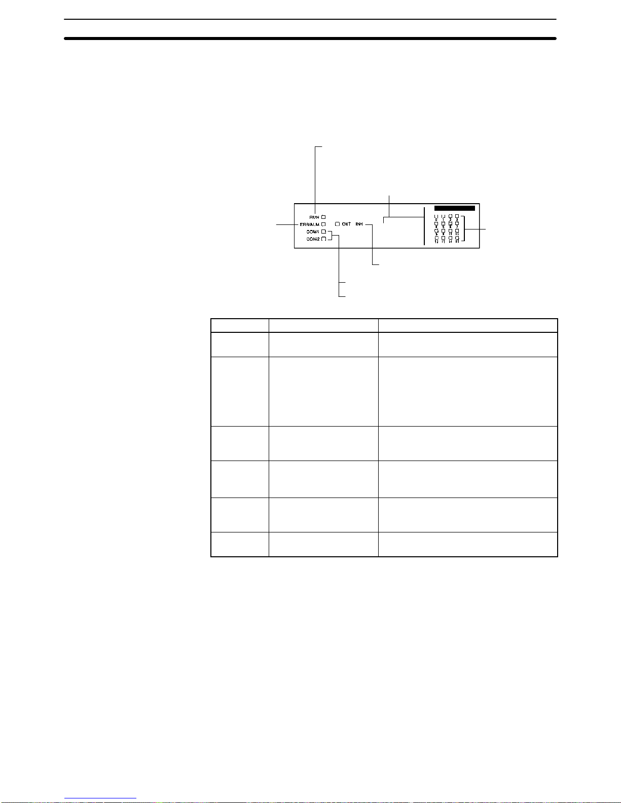
2-1-3 Indicators
CPU Unit indicators provide visual information on the general operation of the
PC. Although not substitutes for proper error programming using the flags and
other error indicators provided in the data areas of memory, these indicators provide ready confirmation of proper operation. CPU Unit indicators are shown
below and are described in the following table.
Input Status
Indicators
RUN indicator (Green)
Error/alarm
indicator (Red)
Peripheral port (COM1) (Orange)
RS-232C port (COM2) (Orange)
Output inhibited indicator (Orange)
CPU21-E
The indicator here depends on the Unit:
CPU43-EV1: Pulse I/O
CPU44-EV1: ABS interface
Indicator Name Function
RUN RUN indicator Lights when the CPU Unit is operating
normally.
ERR/ALM Error/Alarm indicator Flashes when there is a non-fatal error.
The CPU Unit will continue operating.
Lit when there is a fatal error. When this
indicator lights, the RUN indicator will go
off, CPU Unit operation will be stopped,
and all outputs will be turned OFF.
COM1 Peripheral port indicator Flashes then the CPU Unit is
communicating with another device via
the peripheral port.
COM2 RS-232C port indicator
Flashes when the CPU Unit is
communicating with another device via
the RS-232C port. (CQM1-CPU21-E only)
OUT INH Output inhibited indicator Lights when the Output OFF Bit, SR
25215, is turned ON. All PC outputs will
be turned OFF.
0, 1, 2 . . . Input status indicators
Indicate the ON and OFF status of input
bits in IR 000.
CPU Unit Section 2-1

10
2-1-4 PC Modes
The CQM1 PCs have three operating modes: PROGRAM, MONITOR, and
RUN. The PC mode can be changed from the mode selector on the Programming Console.
RUN
MONITOR
PROGRAM
Mode selector
The key cannot be removed when the
mode selector is set to PROGRAM.
Note Some Programming Devices (e.g., the Programming Console) will clear the cur-
rent display and display the new operating mode when the mode selector is
changed. You can change the mode without changing the display by first pressing the SHIFT Key and then changing the setting of the mode selector.
The function of each mode is described briefly below.
PROGRAM Mode PROGRAM mode is used when making basic changes to the PC program or set-
tings, such as transferring, writing, editing, or checking the program, or changing
the PC Setup. The program cannot be executed in PROGRAM mode. Output
points at Output Units will remain OFF, even when the corresponding output bit
is ON.
MONITOR Mode MONITOR mode is used when monitoring program execution, such as making a
trial run of a program. The program is executed just as it is in RUN mode, but bit
status, timer and counter SV/PV, and the data content of most words can be
changed online. Output points at Output Units will be turned ON when the corresponding output bit is ON.
RUN Mode RUN mode is used when operating the PC in normal control conditions. Bit sta-
tus cannot be force set or reset, and SVs, PVs, and data cannot be changed
online.
Note When a program section is displayed on the Programming Console and the PC
is in RUN or MONITOR Mode, the ON/OFF status of bits in that program section
will be displayed in the upper-right corner of the display.
Mode Changes The factors that determine the initial operating mode of the PC (the mode when
the PC is turned on) are listed below in order of importance.
1, 2, 3...
1. No Devices mounted:
If no Peripheral Devices are mounted to the PC, the PC will enter RUN mode
when turned ON unless the startup mode setting in the PC Setup (DM 6600)
has been set to MONITOR or PROGRAM Mode.
2. Programming Console mounted:
If the Programming Console is connected to the PC when PC power is
applied, the PC will enter the mode set on the Programming Console’s mode
selector.
3. Other Peripheral Device mounted:
If a Programming Console is not mounted to the PC, but another Peripheral
Device is connected to the PC, the PC will enter PROGRAM mode.
CPU Unit Section 2-1
!
11
If the PC power supply is already turned on when a Peripheral Device is attached
to the PC, the PC will stay in the same mode it was in before the peripheral
device was attached. If the Programming Console is connected, the PC will
enter the mode set on the Programming Console’s mode selector once the
password has been entered.
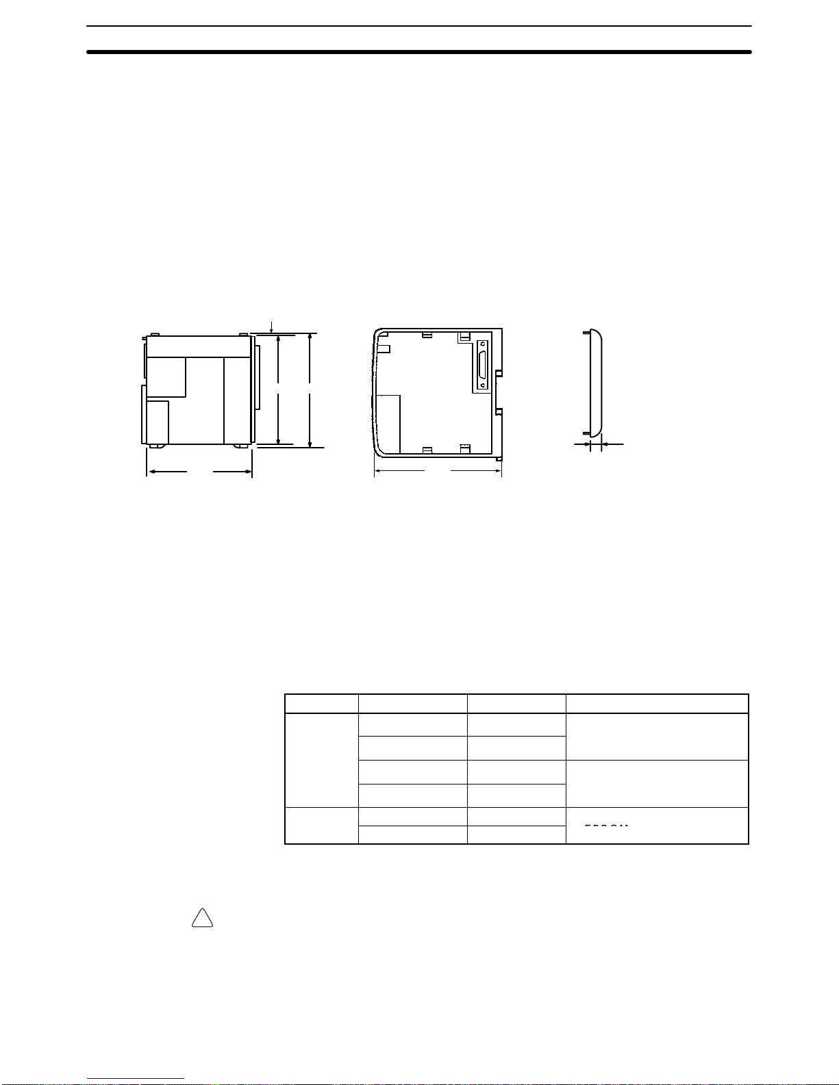
2-1-5 Dimensions and Weights
Dimensions The following diagrams show the dimensions of the CPU Unit and right End
Cover, which covers the Unit at the far right side of the PC. All dimensions are in
millimeters.
CPU Unit Front View CPU Unit Side View End Cover Front View
110 115.7
120
2
13.5
107
Note The depth is the same for all Units.
Weights The CQM1-CPU11-E weighs 520 g max.; the CQM1-CPU21-E and
CQM1-CPU41-EV1, 530 g max. All the other CPU Units weigh 600 g max.
2-1-6 Memory Cassette
Four Memory Cassettes are available as accessories to store the program or PC
Setup. When pin 2 of the CPU Unit’s DIP switch is ON, the contents of the
Memory Cassette will be transferred to the CPU Unit automatically at start-up.
Memory Clock Function Model Comments
EEPROM
No CQM1-ME04K
The Programming Console is
Yes CQM1-ME04R
used to write to
EEPROM
.
(4K words)
No CQM1-ME08K
The Programming Console is
Yes CQM1-ME08R
used to write to
EEPROM
.
(8K words)
EPROM
No CQM1-MP08K
A PROM Writer is used to write
Yes CQM1-MP08R
to EPROM.
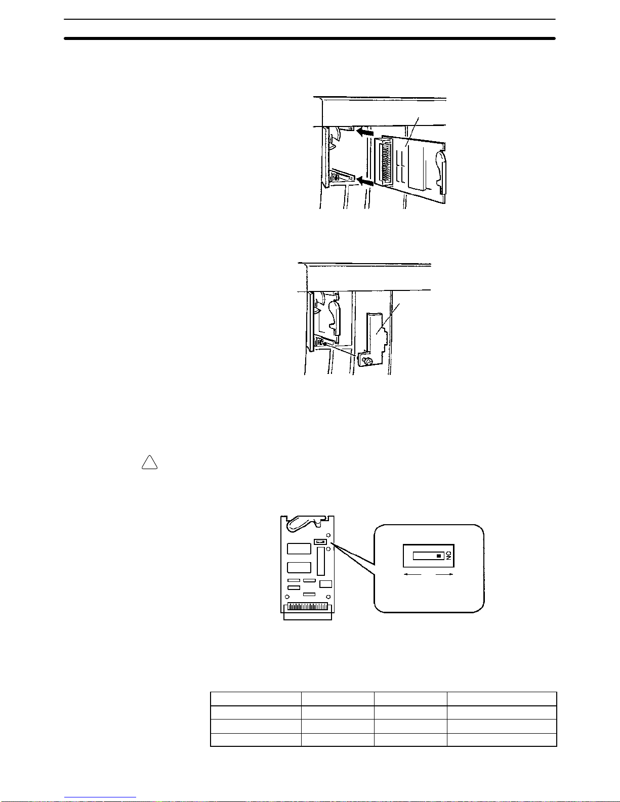
Memory Cassette Installation Follow the procedure below to install a Memory Cassette in the CPU Unit.
Caution Always turn off power to the CQM1 before installing or removing a Memory Cas-
sette.
1, 2, 3...
1. Remove the mounting bracket from inside the memory cassette compartment.
CPU Unit Section 2-1
!
12
2. Slide the Memory Cassette into the CPU Unit on the tracks provided. Press
the Memory Cassette in so that the connectors fit securely.
Memory cassette
3. Replace the bracket as shown below and tighten the screw.
Mounting bracket
EEPROM Write Protection Turn on the write-protect switch on the EEPROM Memory Cassette to prevent
the program or PC Setup from being deleted accidentally. Turn the switch off
when writing to the Memory Cassette.
Caution Always turn off the CQM1 and remove the Memory Cassette when changing the
write-protect switch setting.
Read/write Read-only
(writeprotected)
Note Flag AR 1302 will be ON when the write-protect switch is ON.
EPROM Version The four EPROM chips listed below can be used in the Memory Cassettes.
EPROM Version Capacity Access Speed Model Number
27128 8K words 150 ns ROM-ID-B
27256 16K words 150 ns ROM-JD-B
27512 32K words 150 ns ROM-KD-B
CPU Unit Section 2-1
!
13
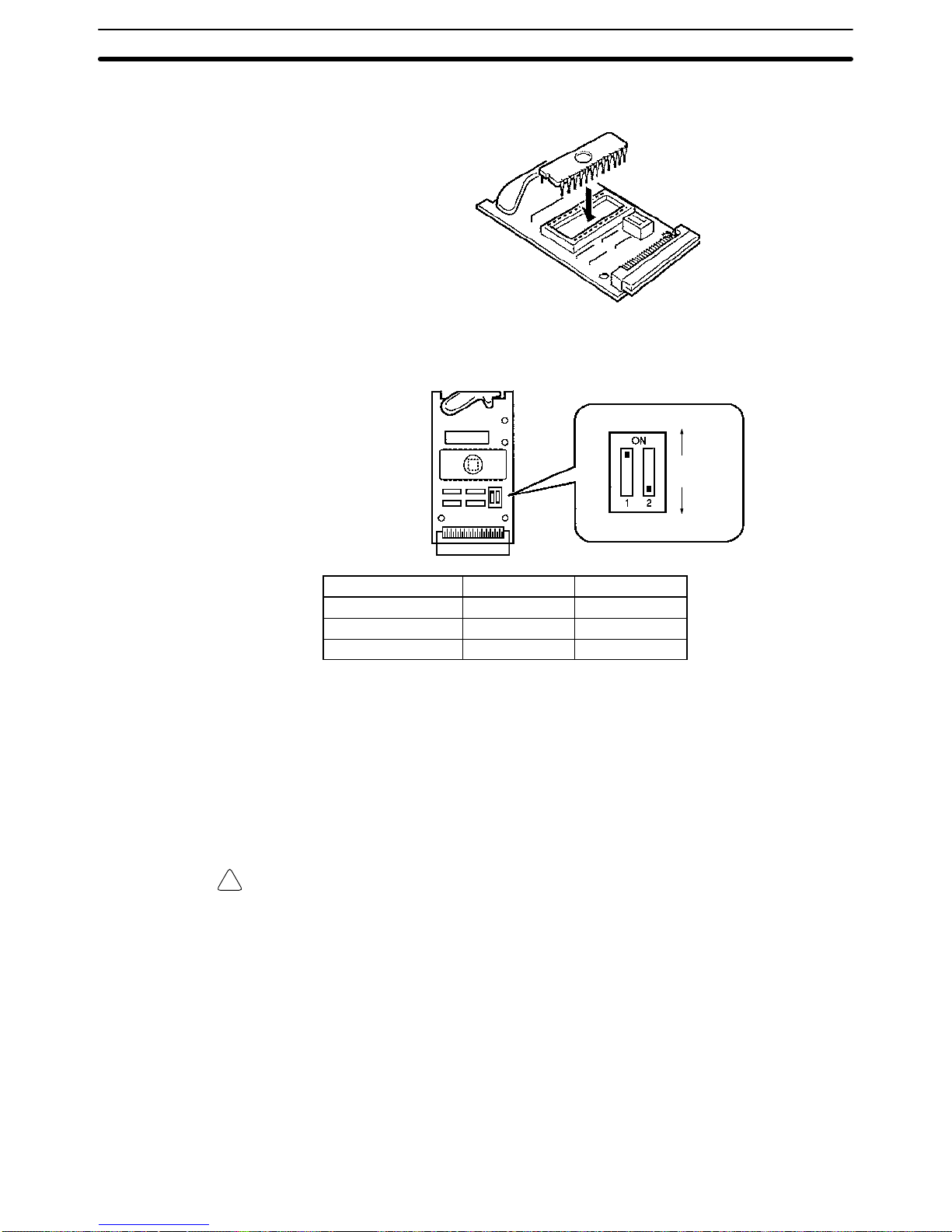
Install an EPROM chip onto the memory cassette as shown in the following diagram.
Be sure that the EPROM version set with the switch on the Memory Cassette
agrees with the EPROM version of the installed chip. Refer to the following diagram and table for the location of the switch and its settings.
ON
OFF
EPROM Version Pin 1 Setting Pin 2 Setting
27128 OFF OFF
27256 ON OFF
27512 ON ON
2-1-7 Battery Replacement
CQM1 CPU Units contain a 3G2A9-BAT08 Battery Set, which must be replaced
when its effective life has expired. The effective life under normal conditions is
approximately 5 years. The ef fective life will be reduced at higher temperatures.
Refer to
Appendix B Battery Service Life
for more details.
A battery error will occur when the voltage of the battery starts to drop, causing
the ALARM/ERROR indicator to flash, causing SR 25308 to turn ON, and generating a battery error message readable from Programming Devices. The battery
must be replaced within one week after a battery error is indicated.
Caution Replace the battery within one week after the first indication that the battery
requires replacement. Always keep a spare Battery Set on hand. It will be highly
unlikely that you will be able to obtain a replacement Battery Set in time otherwise. If the battery is not replaced in time, the user program and other data may
be lost.
Use the following procedure to replace the battery. You must complete this procedure within five minutes after turning off the power to the CQM1 to ensure
memory backup.
1, 2, 3...
1. Turn off the power to the CQM1.
or If the CQM1 is not turned on, turn it on for at least one minute and then turn it
off.
Note If power is not turned on for at least one minute before replacing the
battery, the capacitor that backs up memory when the battery is
CPU Unit Section 2-1
!
14
removed will not be fully charged and memory may be lost before the
new battery is inserted.
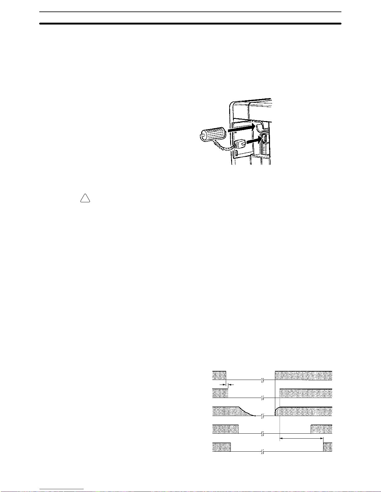
2. Open the compartment on the upper left of the CPU Unit and carefully draw
out the battery.
3. Remove the battery connector.
4. Connect the new battery, place it into the compartment, and close the cover.
The battery error will automatically be cleared when a new battery is inserted.
WARNING Never short-circuit the battery terminals; never charge the battery; never
disassemble the battery; and never heat or incinerate the battery. Doing any of
these may cause the battery to leak, burn, or rupturing resulting in injury, fire, and
possible loss of life or property.
2-1-8 Programmable Controller Power Interruptions
A sequential circuit is built into the PC to handle power interruptions. This circuit
prevents malfunctions due to momentary power loss or voltage drops. A timing
diagram for the operation of this circuit is shown below.
The PC ignores all momentary power failures if the interruption lasts no longer
than 10 ms. If the interruption lasts between 10 and 25 ms, the interruption may
or may not be detected. If the supply voltage drops below 85% of the rated voltage for longer that 25 ms (less for the DC Power Supply), the PC will stop operating and the external outputs will be automatically turned OFF.
Operation is resumed automatically when the voltage is restored to more than
85% of the rated value. The diagram below shows the timing of PC operation
and stopping during a power interruption. The time it takes to detect the power
failure is 5 ms when the power supply is DC.
0.5 s
Power supply
Power
interrupted
Power
restored
Power failure detection
+5 V
CPU Unit operating voltage
Power supply reset
Program RUN
Time lapse until
detection
CPU Unit Section 2-1
!
15
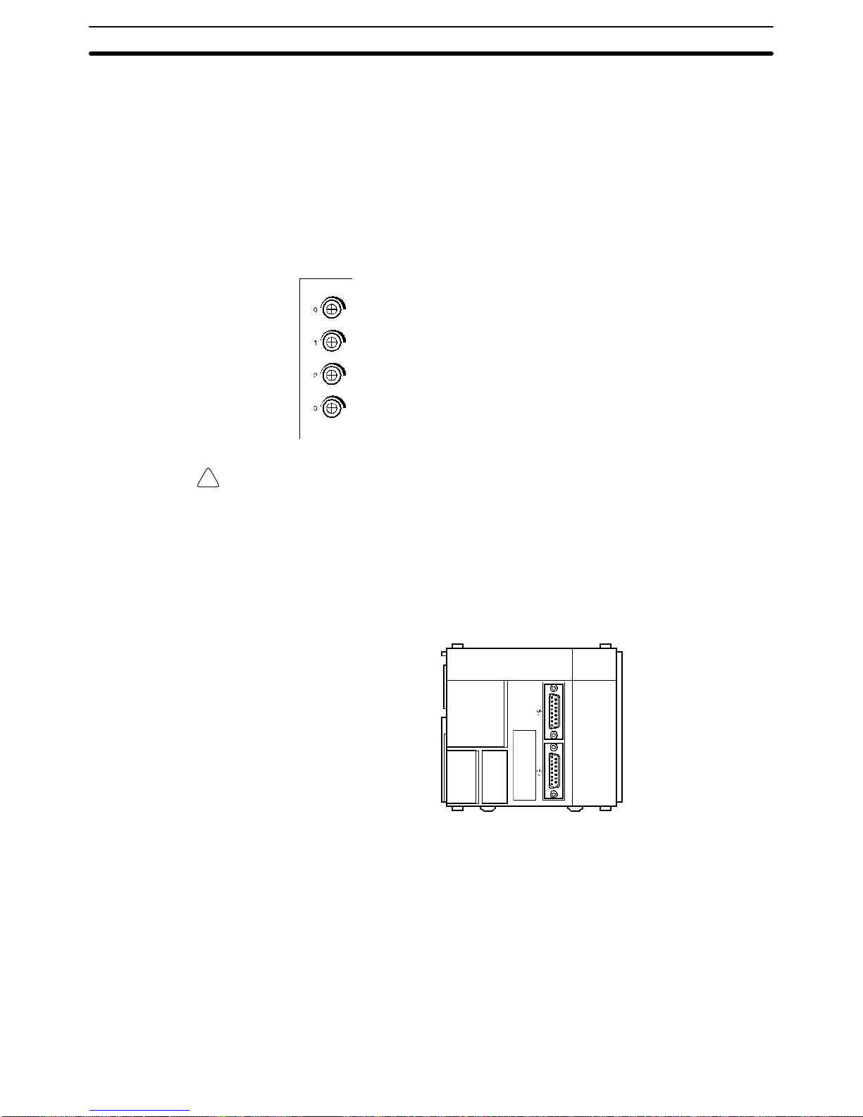
2-1-9 Analog Setting Function
The CQM1-CPU42-EV1 has four volume controls. By adjusting these controls,
the contents of words 220 through 223 can be changed within a range of 0000 to
0200 (in four digits BCD). This is called the “analog setting function.”
A commercially available mini-screwdriver can be used to turn the volume controls. The value increases as they are turned in a clockwise direction.
If words 220 through 223 are designated as the SV for instructions such as TIM,
they cannot be used as the analog timer. With CPU Unit models other than the
CQM1-CPU42-EV1, there is no particular use for words 220 through 223, and
they can be use as IR words.
The value for this control is stored in word 220.
The value for this control is stored in word 221.
The value for this control is stored in word 222.
The value for this control is stored in word 223.
Caution While the power is turned on for CQM1-CPU42-EV1 CPU Units, words 220
through 223 are constantly refreshed with the values from these volume controls. Be sure that writing is not executed within this range by the program or
peripheral devices.
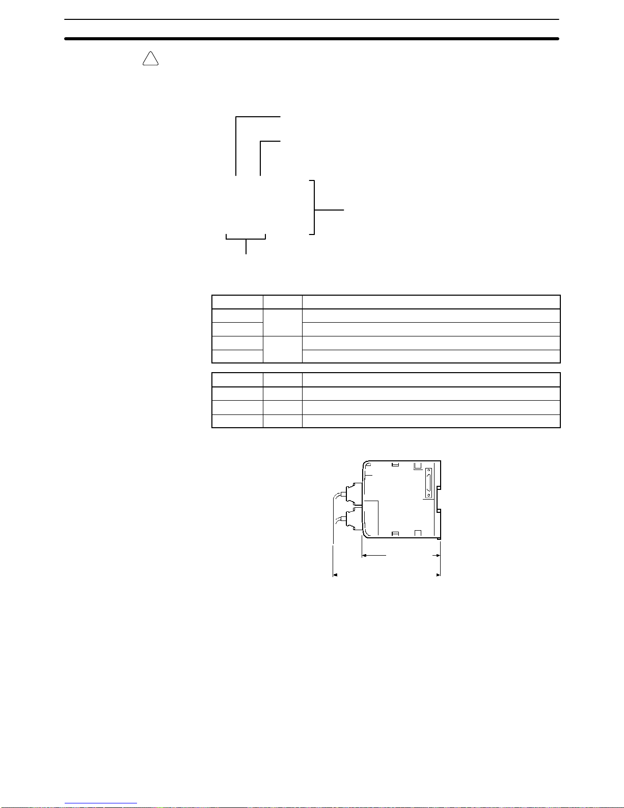
2-1-10Pulse I/O Function
The CQM1-CPU43-EV1 has two dedicated ports (CN1 and CN2) that can input
and output high-speed pulses.
These two ports can be used to perform the functions described below.
Pulse Output Pulses from 10 Hz to 50 kHz can be output. In comparison with pulse output from
a contact, wide-frequency band pulses can be output more smoothly while
changing frequencies.
High-speed pulses input to the port (up to 50 kHz for single phase and
25 kHz for two-phase) can be counted, and processing can be executed
according to the count. There are three kinds of count mode:
• Phase-difference pulse input mode
• Pulse and direction input mode
• Increment/Decrement input mode
High-Speed Counter
Interrupts
CPU Unit Section 2-1
!
16
Caution The following instructions cannot be used when the CQM1-CPU43-EV1 is set to
high-speed counter mode by PC Setup (DM 6611): PLS2 and ACC mode 0.
LED Indicators
Ready (green)
Lit when the pulse I/O function is ready .
Error (red)
Lit when there is an error in the PC Setup for the pulse I/O function, or when operation is interrupted during pulse output.
RDY ERR CW1
CCW1
CW2
CCW2
A2
B2
Z2
A1
B1
Z1
Pulse output (orange)
Refer to the table below.
Pulse input (orange)
Refer to the table below.
Indicator Port Function
CW1
Port 1
Lit during pulse output to port 1 CW.
CCW1 Lit during pulse output to port 1 CCW.
CW2
Port 2
Lit during pulse output to port 2 CW.
CCW2 Lit during pulse output to port 2 CCW.
Port 1 Port 2 Function
A1 A2 Lit when pulse input is ON at phase A for each port.
B1 B2 Lit when pulse input is ON at phase B for each port.
Z1 Z2 Lit when pulse input is ON at phase Z for each port.
Dimensions With Connectors Mounted
107 mm
Approx. 180 mm
Pulse Output Indicators
Pulse Input Indicators
CPU Unit Section 2-1

17
2-1-11 ABS Interface Function
The CQM1-CPU44-EV1 has two dedicated ports (CN1 and CN2) for receiving
grey codes from an absolute-type rotary encoder.
These two ports can be used to carry out absolute-type high-speed counter
interrupts. Grey codes input to the ports can be received at a computation speed
of up to 4 kHz, and processing can be executed according to that value.
LED Indicators
Ready (green)
Lit when the ABS interface function is ready. Turns off
in Program Mode or when an error occurs.
Error (red)
Lit when there is an error in the PC Setup for the ABS interface function.
RDY ERR
IN1
INC1
DEC1
Encoder input (orange)
Refer to the table below.
IN2
INC2
DEC2
Port 1 Port 2 Function
IN1 IN2 Lit when input bit 0 of each port is ON.
INC1 INC2 Lit when value input for each port is incremented.
DEC1 DEC2 Lit when value input for each port is decremented.
Dimensions With Connectors Mounted
107 mm
Approx. 180 mm
Encoder Input Indicators
CPU Unit Section 2-1
 Loading...