

Sysmac CPM1A-20CAR-A, CPM1A-32CAR-A Operation Manual
SYSMAC
CPM1A-20CAR-A
CPM1A-32CAR-A
Programmable Controllers
Operation Manual
Catalog No. P12FAZ1

About this Manual:
The CPM1A is a compact, high-speed Programmable Controller (PLC) designed for control operations in
systems requiring from 10 to 100 I/O points per PLC. There are three manuals describing the setup and
operation of the CPM1A: the CPM1A with AC Inputs Operation Manual (P12FAZ1), the CPM1A Operation
Manual (W317) and the CQM1/CPM1/CPM1A/SRM1 Programming Manual (W228).
This manual describes the system configuration and installation of the CPM1A with AC Inputs and provides a basic explanation of operating procedures for the Programming Consoles. It also introduces the
capabilities of the SYSMAC Support Software (SSS). Read this manual first to acquaint yourself with the
CPM1A with AC Inputs.
The CQM1/CPM1/CPM1A/SRM1 Programming Manual (W228) provides detailed descriptions of the
CPM1A’s programming functions. The SYSMAC Support Software Operation Manuals: Basics and C- se-
ries PLCs (W247 and W248) provide descriptions of SSS operations for the CPM1A and other SYSMAC
C-series PLCs. The SYSMAC- CPT Support Software Quick Start Guide (W332) and User Manual
(W333) provide descriptions of ladder diagram operations in the Windows environment.
Please read this manual carefully and be sure you understand the information provide before attempting
to install and operate the CPM1A.
Section 1 gives a brief overview of the steps involved in developing of a CPM1A System, describes the
possible system configurations, and describes the CPM1A’s special features and functions.
Section 2 provides the technical specifications of the Units that go together to create a CPM1A PLC and
describes the main components of the Units.
Section 3 describes how to install and wire a CPM1A PLC.
Section 4 describes SSS capabilities, how to connect the Programming Console, and how to perform the
various Programming Console operations.
Section 5 describes how to perform a test run and how to diagnose and correct the hardware and soft-
ware errors that can occur during PLC operation.
Appendix A provides tables of CPM1A Units and related products.
Appendix B provides the dimensions of CPM1A Units.
!
W ARNING Failure to read and understand the information provided in this manual may result in
personal injury or death, damage to the product, or product failure. Please read each
section in its entirety and be sure you understand the information provided in the section
and related sections before attempting any of the procedures or operations given.
i

ii

Notice:
OMRON,199
9
OMRON products are manufactured for use according to proper procedures by a qualified operator
and only for the purposes described in this manual.
The following conventions are used to indicate and classify precautions in this manual. Always heed
the information provided with them. Failure to heed precautions can result in injury to people or damage to the product.
!
DANGER Indicates information that, if not heeded, is likely to result in loss of life orserious
injury.
W ARNING Indicates information that, if not heeded, could possibly result in loss of life or
!
serious injury.
Caution Indicates information that, if not heeded, could result in relatively serious or mi-
!
nor injury, damage to the product, or faulty operation.
OMRON Product References
All OMRON products are capitalized in this manual. The word “Unit” is also capitalized when it refers
to an OMRON product, regardless of whether or not it appears in the proper name of the product.
The abbreviation “Ch,” which appears in some displays and on some OMRON products, often means
“word” and is abbreviated “Wd” in documentation in this sense.
The acronym PLC means Programmable Controller . However, please note: within software
programming references, you will see the acronym PC (used to indicate PLC).
For example: PC Setup (as used within the software program) refers to PLC Setup.
Visual Aids
The following headings appear in the left column of the manual to help you locate different types of
information.
Ó
All rights reserved. No part of this publication may be reproduced, stored in a retrieval system, or transmitted, in any
form, or by any means, mechanical, electronic, photocopying, recording, or otherwise, without the prior written permission of OMRON.
No patent liability is assumed with respect to the use of the information contained herein. Moreover, because OMRON is
constantly striving to improve its high-quality products, the information contained in this manual is subject to change
without notice. Every precaution has been taken in the preparation of this manual. Nevertheless, OMRON assumes no
responsibility for errors or omissions. Neither is any liability assumed for damages resulting from the use of the information contained in this publication.
Note Indicates information of particular interest for efficient and convenient operation
of the product.
1, 2, 3... 1. Indicates lists of one sort or another , such as procedures, checklists, etc.
iii

iv

TABLE OF CONTENTS
PRECAUTIONS xi. . . . . . . . . . . . . . . . . . . . . . . . . . . . . . . . .
1 Intended Audience xii. . . . . . . . . . . . . . . . . . . . . . . . . . . . . . . . . . . . . . . . . . . . . . . . . . . . . . . . .
2 General Precautions xii. . . . . . . . . . . . . . . . . . . . . . . . . . . . . . . . . . . . . . . . . . . . . . . . . . . . . . . .
3 Safety Precautions xii. . . . . . . . . . . . . . . . . . . . . . . . . . . . . . . . . . . . . . . . . . . . . . . . . . . . . . . . .
4 Operating Environment Precautions xii. . . . . . . . . . . . . . . . . . . . . . . . . . . . . . . . . . . . . . . . . . . .
5 Application Precautions xiii. . . . . . . . . . . . . . . . . . . . . . . . . . . . . . . . . . . . . . . . . . . . . . . . . . . . .
6 EC Directives xvi. . . . . . . . . . . . . . . . . . . . . . . . . . . . . . . . . . . . . . . . . . . . . . . . . . . . . . . . . . . . .
SECTION 1
Introduction 1. . . . . . . . . . . . . . . . . . . . . . . . . . . . . . . . . . . .
1-1 CPM1A Features and Functions 2. . . . . . . . . . . . . . . . . . . . . . . . . . . . . . . . . . . . . . . . . . .
1-1-1 CPM1A Features 2. . . . . . . . . . . . . . . . . . . . . . . . . . . . . . . . . . . . . . . . . . . . . . . .
1-1-2 I/O Terminal and IR Bit Allocation 3. . . . . . . . . . . . . . . . . . . . . . . . . . . . . . . . . .
1-1-3 CPM1A Functions 4. . . . . . . . . . . . . . . . . . . . . . . . . . . . . . . . . . . . . . . . . . . . . . .
1-2 System Configuration 8. . . . . . . . . . . . . . . . . . . . . . . . . . . . . . . . . . . . . . . . . . . . . . . . . . .
1-2-1 CPU Unit and Expansion I/O Module Configuration 8. . . . . . . . . . . . . . . . . . . . .
1-2-2 Host Link Communications 9. . . . . . . . . . . . . . . . . . . . . . . . . . . . . . . . . . . . . . . .
1-2-3 1-to-1 Communications Links 11. . . . . . . . . . . . . . . . . . . . . . . . . . . . . . . . . . . . . .
1-2-4 NT Link Communications 12. . . . . . . . . . . . . . . . . . . . . . . . . . . . . . . . . . . . . . . . .
1-2-5 Peripheral Device Connections 12. . . . . . . . . . . . . . . . . . . . . . . . . . . . . . . . . . . . .
SECTION 2
Unit Specifications and Components 15. . . . . . . . . . . . . . . . .
2-1 Specifications 16. . . . . . . . . . . . . . . . . . . . . . . . . . . . . . . . . . . . . . . . . . . . . . . . . . . . . . . . .
2-1-1 General Specifications 16. . . . . . . . . . . . . . . . . . . . . . . . . . . . . . . . . . . . . . . . . . . .
2-1-2 Characteristics 17. . . . . . . . . . . . . . . . . . . . . . . . . . . . . . . . . . . . . . . . . . . . . . . . . .
2-1-3 I/O Specifications 19. . . . . . . . . . . . . . . . . . . . . . . . . . . . . . . . . . . . . . . . . . . . . . .
2-1-4 Communications Adapter Specifications 23. . . . . . . . . . . . . . . . . . . . . . . . . . . . . .
2-2 Unit Components 24. . . . . . . . . . . . . . . . . . . . . . . . . . . . . . . . . . . . . . . . . . . . . . . . . . . . . .
2-2-1 CPU Unit Components 24. . . . . . . . . . . . . . . . . . . . . . . . . . . . . . . . . . . . . . . . . . .
2-2-2 Expansion I/O Module Components 26. . . . . . . . . . . . . . . . . . . . . . . . . . . . . . . . .
2-2-3 Communications Adapter Components 27. . . . . . . . . . . . . . . . . . . . . . . . . . . . . . .
SECTION 3
Installation and Wiring 29. . . . . . . . . . . . . . . . . . . . . . . . . . .
3-1 Design Precautions 30. . . . . . . . . . . . . . . . . . . . . . . . . . . . . . . . . . . . . . . . . . . . . . . . . . . . .
3-1-1 Power Supply W iring 30. . . . . . . . . . . . . . . . . . . . . . . . . . . . . . . . . . . . . . . . . . . . .
3-1-2 Interlock and Limit Circuits 30. . . . . . . . . . . . . . . . . . . . . . . . . . . . . . . . . . . . . . .
3-1-3 Power Supply Voltage 30. . . . . . . . . . . . . . . . . . . . . . . . . . . . . . . . . . . . . . . . . . . .
3-1-4 CPM1A Power Interruptions 30. . . . . . . . . . . . . . . . . . . . . . . . . . . . . . . . . . . . . . .
3-2 Selecting an Installation Site 31. . . . . . . . . . . . . . . . . . . . . . . . . . . . . . . . . . . . . . . . . . . . . .
3-2-1 Installation Site Conditions 31. . . . . . . . . . . . . . . . . . . . . . . . . . . . . . . . . . . . . . . .
3-2-2 Panel/Cabinet Installation 32. . . . . . . . . . . . . . . . . . . . . . . . . . . . . . . . . . . . . . . . .
3-3 Installing the CPM1A 33. . . . . . . . . . . . . . . . . . . . . . . . . . . . . . . . . . . . . . . . . . . . . . . . . . .
3-3-1 CPM1A Orientation 33. . . . . . . . . . . . . . . . . . . . . . . . . . . . . . . . . . . . . . . . . . . . .
3-3-2 CPM1A Installation 33. . . . . . . . . . . . . . . . . . . . . . . . . . . . . . . . . . . . . . . . . . . . .
3-3-3 Connecting an Expansion I/O Module 35. . . . . . . . . . . . . . . . . . . . . . . . . . . . . . .
i

3-4 W iringand Connections 36. . . . . . . . . . . . . . . . . . . . . . . . . . . . . . . . . . . . . . . . . . . . . . . . .
3-4-1 General Precautions for W iring 36. . . . . . . . . . . . . . . . . . . . . . . . . . . . . . . . . . . . .
3-4-2 Ground W iring 38. . . . . . . . . . . . . . . . . . . . . . . . . . . . . . . . . . . . . . . . . . . . . . . . .
3-4-3 Power Supply W iring 38. . . . . . . . . . . . . . . . . . . . . . . . . . . . . . . . . . . . . . . . . . . . .
3-4-4 Input W iring 40. . . . . . . . . . . . . . . . . . . . . . . . . . . . . . . . . . . . . . . . . . . . . . . . . . .
3-4-5 Output W iring 43. . . . . . . . . . . . . . . . . . . . . . . . . . . . . . . . . . . . . . . . . . . . . . . . . .
3-4-6 Peripheral Device Connection 45. . . . . . . . . . . . . . . . . . . . . . . . . . . . . . . . . . . . . .
3-4-7 Host Link Connections 45. . . . . . . . . . . . . . . . . . . . . . . . . . . . . . . . . . . . . . . . . . .
3-4-8 One-to-one PLC Connections 48. . . . . . . . . . . . . . . . . . . . . . . . . . . . . . . . . . . . . .
3-4-9 NT Link Connections 49. . . . . . . . . . . . . . . . . . . . . . . . . . . . . . . . . . . . . . . . . . . .
SECTION 4
Using Peripheral Devices 51. . . . . . . . . . . . . . . . . . . . . . . . . .
4-1 Support Software Capabilities 52. . . . . . . . . . . . . . . . . . . . . . . . . . . . . . . . . . . . . . . . . . . . .
4-1-1 SSS System Setup 52. . . . . . . . . . . . . . . . . . . . . . . . . . . . . . . . . . . . . . . . . . . . . . .
4-1-2 CPM1A Restrictions and Precautions 52. . . . . . . . . . . . . . . . . . . . . . . . . . . . . . . .
4-1-3 Offline Operations 53. . . . . . . . . . . . . . . . . . . . . . . . . . . . . . . . . . . . . . . . . . . . . . .
4-1-4 Online Operations 55. . . . . . . . . . . . . . . . . . . . . . . . . . . . . . . . . . . . . . . . . . . . . . .
4-1-5 Offline and Online Operations 56. . . . . . . . . . . . . . . . . . . . . . . . . . . . . . . . . . . . . .
4-2 Using a Programming Console 57. . . . . . . . . . . . . . . . . . . . . . . . . . . . . . . . . . . . . . . . . . . .
4-2-1 Compatible Programming Consoles 57. . . . . . . . . . . . . . . . . . . . . . . . . . . . . . . . .
4-2-2 Connecting the Programming Console 58. . . . . . . . . . . . . . . . . . . . . . . . . . . . . . .
4-2-3 Preparation for Operation 59. . . . . . . . . . . . . . . . . . . . . . . . . . . . . . . . . . . . . . . . .
4-2-4 Entering the Password 59. . . . . . . . . . . . . . . . . . . . . . . . . . . . . . . . . . . . . . . . . . . .
4-2-5 Changing the CPM1A ’s Mode 60. . . . . . . . . . . . . . . . . . . . . . . . . . . . . . . . . . . . . .
4-3 Programming Console Operations 61. . . . . . . . . . . . . . . . . . . . . . . . . . . . . . . . . . . . . . . . . .
4-3-1 Overview 61. . . . . . . . . . . . . . . . . . . . . . . . . . . . . . . . . . . . . . . . . . . . . . . . . . . . . .
4-3-2 Clearing Memory 62. . . . . . . . . . . . . . . . . . . . . . . . . . . . . . . . . . . . . . . . . . . . . . .
4-3-3 Reading/Clearing Error Messages 63. . . . . . . . . . . . . . . . . . . . . . . . . . . . . . . . . . .
4-3-4 Buzzer Operation 63. . . . . . . . . . . . . . . . . . . . . . . . . . . . . . . . . . . . . . . . . . . . . . .
4-3-5 Setting and Reading a Program Memory Address 64. . . . . . . . . . . . . . . . . . . . . . .
4-3-6 Instruction Search 64. . . . . . . . . . . . . . . . . . . . . . . . . . . . . . . . . . . . . . . . . . . . . . .
4-3-7 Bit Operand Search 65. . . . . . . . . . . . . . . . . . . . . . . . . . . . . . . . . . . . . . . . . . . . . .
4-3-8 Inserting and Deleting Instructions 65. . . . . . . . . . . . . . . . . . . . . . . . . . . . . . . . . .
4-3-9 Entering or Editing Programs 67. . . . . . . . . . . . . . . . . . . . . . . . . . . . . . . . . . . . . .
4-3-10 Checking the Program 70. . . . . . . . . . . . . . . . . . . . . . . . . . . . . . . . . . . . . . . . . . . .
4-3-11 Bit, Digit, W ordMonitor 70. . . . . . . . . . . . . . . . . . . . . . . . . . . . . . . . . . . . . . . . . .
4-3-12 Differentiation Monitor 72. . . . . . . . . . . . . . . . . . . . . . . . . . . . . . . . . . . . . . . . . . .
4-3-13 Binary Monitor 73. . . . . . . . . . . . . . . . . . . . . . . . . . . . . . . . . . . . . . . . . . . . . . . . .
4-3-14 3-W ordMonitor 73. . . . . . . . . . . . . . . . . . . . . . . . . . . . . . . . . . . . . . . . . . . . . . . .
4-3-15 Signed Decimal Monitor 74. . . . . . . . . . . . . . . . . . . . . . . . . . . . . . . . . . . . . . . . . .
4-3-16 Unsigned Decimal Monitor 74. . . . . . . . . . . . . . . . . . . . . . . . . . . . . . . . . . . . . . . .
4-3-17 3-W ordData Modification 75. . . . . . . . . . . . . . . . . . . . . . . . . . . . . . . . . . . . . . . . .
4-3-18 Changing Timer ,Counter SV 75. . . . . . . . . . . . . . . . . . . . . . . . . . . . . . . . . . . . . . .
4-3-19 Hexadecimal, BCD Data Modification 76. . . . . . . . . . . . . . . . . . . . . . . . . . . . . . .
4-3-20 Binary Data Modification 77. . . . . . . . . . . . . . . . . . . . . . . . . . . . . . . . . . . . . . . . .
4-3-21 Signed Decimal Data Modification 78. . . . . . . . . . . . . . . . . . . . . . . . . . . . . . . . . .
4-3-22 Unsigned Decimal Data Modification 78. . . . . . . . . . . . . . . . . . . . . . . . . . . . . . . .
4-3-23 Force Set, Reset 79. . . . . . . . . . . . . . . . . . . . . . . . . . . . . . . . . . . . . . . . . . . . . . . . .
4-3-24 Clear Force Set/Reset 79. . . . . . . . . . . . . . . . . . . . . . . . . . . . . . . . . . . . . . . . . . . .
4-3-25 Hex-ASCII Display Change 80. . . . . . . . . . . . . . . . . . . . . . . . . . . . . . . . . . . . . . . .
4-3-26 Displaying the Cycle Time 80. . . . . . . . . . . . . . . . . . . . . . . . . . . . . . . . . . . . . . . .
4-4 Programming Example 81. . . . . . . . . . . . . . . . . . . . . . . . . . . . . . . . . . . . . . . . . . . . . . . . . .
ii

4-4-1 Preparatory Operations 81. . . . . . . . . . . . . . . . . . . . . . . . . . . . . . . . . . . . . . . . . . .
4-4-2 Example Program 82. . . . . . . . . . . . . . . . . . . . . . . . . . . . . . . . . . . . . . . . . . . . . . .
4-4-3 Programming Procedures 83. . . . . . . . . . . . . . . . . . . . . . . . . . . . . . . . . . . . . . . . . .
4-4-4 Checking the Program 85. . . . . . . . . . . . . . . . . . . . . . . . . . . . . . . . . . . . . . . . . . . .
4-4-5 Test Run in MONITOR Mode 86. . . . . . . . . . . . . . . . . . . . . . . . . . . . . . . . . . . . . .
SECTION 5
Test Runs and Error Processing 87. . . . . . . . . . . . . . . . . . . . .
5-1 Initial System Checks and Test Run Procedure 88. . . . . . . . . . . . . . . . . . . . . . . . . . . . . . . .
5-1-1 Initial System Checks 88. . . . . . . . . . . . . . . . . . . . . . . . . . . . . . . . . . . . . . . . . . . .
5-1-2 CPM1A Test Run Procedure 88. . . . . . . . . . . . . . . . . . . . . . . . . . . . . . . . . . . . . . .
5-1-3 Flash Memory Precautions 89. . . . . . . . . . . . . . . . . . . . . . . . . . . . . . . . . . . . . . . .
5-2 The CPM1A Cycle 90. . . . . . . . . . . . . . . . . . . . . . . . . . . . . . . . . . . . . . . . . . . . . . . . . . . . .
5-3 Self-diagnosis Functions 91. . . . . . . . . . . . . . . . . . . . . . . . . . . . . . . . . . . . . . . . . . . . . . . . .
5-3-1 Non-fatal Errors 91. . . . . . . . . . . . . . . . . . . . . . . . . . . . . . . . . . . . . . . . . . . . . . . . .
5-3-2 Fatal Errors 91. . . . . . . . . . . . . . . . . . . . . . . . . . . . . . . . . . . . . . . . . . . . . . . . . . . .
5-3-3 Identifying Errors 92. . . . . . . . . . . . . . . . . . . . . . . . . . . . . . . . . . . . . . . . . . . . . . .
5-3-4 User-defined Errors 92. . . . . . . . . . . . . . . . . . . . . . . . . . . . . . . . . . . . . . . . . . . . . .
5-4 Programming Console Operation Errors 93. . . . . . . . . . . . . . . . . . . . . . . . . . . . . . . . . . . . .
5-5 Programming Errors 93. . . . . . . . . . . . . . . . . . . . . . . . . . . . . . . . . . . . . . . . . . . . . . . . . . . .
5-6 Troubleshooting Flowcharts 95. . . . . . . . . . . . . . . . . . . . . . . . . . . . . . . . . . . . . . . . . . . . . .
5-7 Maintenance Inspections 103. . . . . . . . . . . . . . . . . . . . . . . . . . . . . . . . . . . . . . . . . . . . . . . .
5-8 Handling Precautions 104. . . . . . . . . . . . . . . . . . . . . . . . . . . . . . . . . . . . . . . . . . . . . . . . . . .
Appendices
A Standard Models 105. . . . . . . . . . . . . . . . . . . . . . . . . . . . . . . . . . . . . . . . . . . . . . . . . . . . . . . . .
B Dimensions 107. . . . . . . . . . . . . . . . . . . . . . . . . . . . . . . . . . . . . . . . . . . . . . . . . . . . . . . . . . . . .
Glossary 111. . . . . . . . . . . . . . . . . . . . . . . . . . . . . . . . . . . . . . . .
Index 127. . . . . . . . . . . . . . . . . . . . . . . . . . . . . . . . . . . . . . . . . .
Revision History 131. . . . . . . . . . . . . . . . . . . . . . . . . . . . . . . . .
iii

iv

PRECAUTIONS
This section provides general precautions for using the Programmable Controller (PLC) and related devices.
Theinformation contained inthis section isimportant for thesafe andreliable applicationof thePLC. Youmust read
this section and understand the information contained before attempting to set up or operate a PLC system.
1 Intended Audience xii...........................................................
2 General Precautions xii..........................................................
3 Safety Precautions xii...........................................................
4 Operating Environment Precautions xii.............................................
5 Application Precautions xiii.......................................................
6 EC Directives xvi...............................................................
xi

1 Intended Audience
This manual is intended for the following personnel, who must also have knowledge of electrical systems (an electrical engineer or the equivalent).
• Personnel in charge of installing FA systems.
• Personnel in charge of designing FA systems.
• Personnel in charge of managing FA systems and facilities.
2 General Precautions
The user must operate the product according to the performance specifications
described in the operation manuals.
Beforeusing the productunder conditionswhich arenot describedin the manual
or applying the product to nuclear control systems, railroad systems, aviation
systems, vehicles, combustion systems, medical equipment, amusement machines, safety equipment, and other systems, machines, and equipment that
may have a serious influence on lives and property if used improperly, consult
your OMRON representative.
Make sure that the ratings and performance characteristics of the product are
sufficientfor the systems, machines,and equipment, and besure to provide the
systems, machines, and equipment with double safety mechanisms.
This manual provides information for programming and operating OMRON
PLCs. Be sure to read this manual before attempting to use the software and
keep this manual close at hand for reference during operation.
6EC Directives
WARNING
!
It is extremely important that a PLC and all PLC Units be used for the specified
purpose and under the specified conditions, especially in applications that can
directly or indirectly affect human life. Y ou must consult with your OMRON
representative before applying a PLC System to the abov ementioned
applications.
3 Safety Precautions
WARNING
!
WARNING
!
WARNING
!
Neverattempt to disassemble any Units whilepower is being supplied. Doingso
may result in serious electrical shock or electrocution.
Never touch any of the terminals while power is being supplied. Doing so may
result in serious electrical shock or electrocution.
The PLC system is provided as “open equipment.” There are live terminals
which must be enclosed to provide the appropriate level of protection from the
risk of electric shock.
4 Operating Environment Precautions
Do not operate the control system in the following places.
• Locations subject to direct sunlight.
• Locations subject to temperatures or humidity outside the range specified in
the specifications.
• Locations subject tocondensation as theresultof severe changesin temperature.
xii

• Locations subject to corrosive or flammable gases.
• Locations subject to dust (especially iron dust) or salts.
• Locations subject to shock or vibration.
• Locations subject to exposure to water, oil, or chemicals.
• Take appropriate and sufficient countermeasures when installing systems in
the following locations.
• Locations subject to static electricity or other forms of noise.
• Locations subject to strong electromagnetic fields.
• Locations subject to possible exposure to radioactivity.
• Locations close to power supplies.
Caution The operating environment of the PLC System can have a large effect on the
!
longevity and reliability of the system. Improper operating environments can
lead to malfunction, failure, and other unforeseeable problems with the PLC
System. Be sure that the operating environment is within the specified conditions at installation and remains within the specified conditions during the life of
the system.
5 Application Precautions
Observe the following precautions when using the PLC.
5Application Precautions
WARNING
!
Caution Execute online edit only after confirming that no adverse effects will be caused
!
Caution Tighten the screws on the terminal block of the AC Power Supply Unit to the
!
Caution Always clear memory before beginning to program the CPM1A. Although
!
Failure to abide by the following precautions could lead to serious or possibly
fatal injury. Always heed these precautions.
• Always ground the system to 100 Ω or less when installing the system to protect against electrical shock.
• Always turn off the power supply to the PLC before attempting any of the following. Performing any of the following with the power supply turned on may
lead to electrical shock:
• Mounting or removing any Units.
• Assembling any Unit.
• Connecting or disconnecting any cables or wiring.
by extending the cycle time. Otherwise, the input signals may not be readable.
torque specified in this manual. The loose screws may result in short-circuit,
malfunction, or burning.
memory is cleared before the CPU Unit is shipped (except for bits with specific
functions),AR 1314,which turns ONwhen theinternal capacitorcannot back up
memory, may have turned ON during shipment.
Caution If the CPM1A will be turned off for periods exceeding the data backup period of
!
theinternal capacitor,designthe system so that it willnot be influencedif data in
the DM, HR, and CNT areas is cleared when power is turned off.
Caution Eitherswitch theCPM1A to RUNor MONITORmode, orturn offandon powerto
!
the CPM1A after changing from a Programming Device any data that is backed
up in flash memory. This data includes the user program, read-only DM area
(DM 6144 to DM 6599), and the PC Setup (DM 6600 to DM 6655).
xiii
6EC Directives
• The user program and memory area data in the CPM1A are backed up either
by an internal capacitor or in flash memory as shown in the following table.
Backup method Data
Internal capacitor Read/write DM area (DM 0000 to DM 0999, DM 1022, and
Flash memory User program
Note 1. The IR, TR, LR, and timer areas are not normally backed up when power is
turned off and all contents will be cleared the next time power is turned on.
(ThePC Setup settingin DM6601 canbe usedto backup thisdata. Referto
details on the PC Setup later in this manual for details.)
2. Thebits in the AR and SR areas have special functions and are set according to these functions when power is turned on.
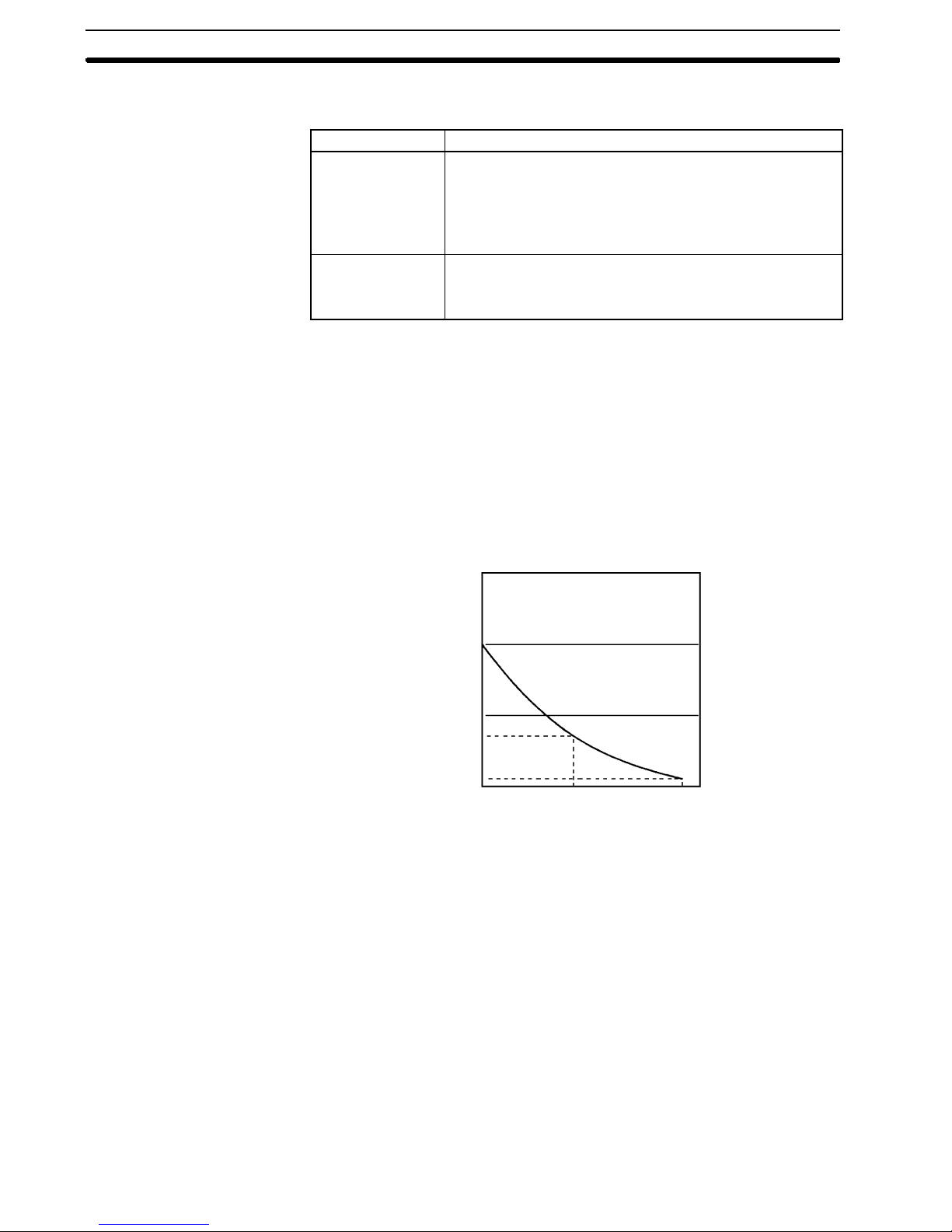
• The capacitor backup time depends on the ambient temperature, as shown in
the following graph. The backup time, however,assumes that the capacitor is
fully charged, which requires that power be supplied to the CPU Unit continuously for at least 15 minutes.
DM 1023)
Error log area (DM 1000 to DM 1021)
HR area (HR 00 to HR 19)
Counter area (CNT 000 to CNT 127)
Read-only DM area (DM 6144 to DM 6599)
PC Setup (DM 6600 to DM 6655)
20
10
Backup time (days)
7
1
25 40 80
Ambient temperature (_C)
If the power remains off for a period exceeding the data backup period,
AR 1314 will turn ON to indicate that the capacitor can no longer back up data
and the data backed up by the capacitor will be cleared. AR 1314 will remain
ON unless it is turned OFF using I/O monitor operations, using memory clear
operations, or from the user program.
If desired, the PC Setup setting in DM 6604 can be set to create a fatal error
and thus stop the system when AR 1314 goes ON.
• The data stored in flash memory will not be lost even if power remains off for a
period exceeding the data backup period, because the data stored in flash
memory will be read to the CPU Unit when the CPM1A is turned on.
• If the poweris turned off without changing themode from PROGRAM mode to
RUNor MONITORmode afterhaving madechanges inthe datathat isbacked
upin flashmemory,the changes willnot be written to flash memory.If the power is then left off for more than 20 days (at 25_C), the changes (i.e., the contents of the RAM) will be erased and the data values will become undefined.
xiv

Caution Failure to abide by the followingprecautions could lead tofaulty operation or the
!
PLC or the system or could damage the PLC or PLC Units. Always heed these
precautions.
• Use theUnits onlywith thepower supplies andvoltages specifiedin theoperation manuals.
• Take appropriate measures to ensure that the specified power with the rated
voltage and frequency is supplied, particularly in places where thepower supply is unstable.
• Provide circuit breakers and other safety measures to provide protection
against shorts in external wiring.
• Do not apply voltages exceeding the rated input voltage to input sections.
• Do not apply voltages exceeding the maximum switching capacity to output
sections.
• Always disconnect the LG terminal when performing withstand voltage tests.
• Always connectto aclass-3 ground(to 100Ω or less)when installingthe Units.
• Always turn the power supply to the PLC off before attempting any of the fol-
lowing:
• Mounting or dismounting I/O Modules, CPU Units, Memory Cassettes, or
any other Units.
• Assembling the Units.
• Setting the DIP switch or rotary switch.
• Connecting or wiring the cables.
• Connecting or disconnecting the connectors.
• Do not attempt to take any Units apart, to repair any Units, or to modify any
Units in any way.
• Be sure that all the mounting screws, terminal screws, and cable connector
screws are tightened to the torque specified in this manual.
• Besuretoattachlabels suppliedwith the CPM1Aonto theCPM1Awhenwiring
in order to prevent wiring cuttings from entering in the Unit.
• Remove thelabelsafter thecompletionof wiringto ensureproper heat dissipation.
• Use either crimp terminals or single-wire lines for wiring. Do not connect bare
stranded wires directly to terminals.
• Double-check all the wiring before turning on the power supply.
• Be sure to check polarity and directions when connecting terminal blocks or
connectors.
• Be sure that the terminal blocks, Memory Units, expansion cables, and other
items with locking devices are properly locked into place.
• Check the user program for proper execution before actually running it on the
Unit.
• Be sure to confirm that no adverse effect will occur in the equipment before
changing the operation mode of the PLC.
• Be sure to confirm that no adverse effect will occur in the equipment before
executing forced set/reset.
• Be sure to confirm that no adverse effect will occur in the equipment before
changing the set values or present values.
• Be sure to resume operation only after transferring to the replaced CPU Unit
thecontents of thedata memory orhold relay required forresumingoperation.
• Never pull on, bend to extreme angles, or place heavy objects on cables.
• Install all Units according to instructions in the operation manuals.
5Application Precautions
xv

Caution Thefollowingprecautions are necessaryto ensurethe generalsafety of thesys-
!
Caution Do not touch the Expansion I/O Module Connecting Cable while the power is
!
6 EC Directives
6EC Directives
tem. Always heed these precautions.
• Fail-safe measures must be taken by the customer to ensure safety in the
eventof incorrect, missing, orabnormal signals caused by broken signal lines,
momentary power interruptions, or other causes.
• The interlock circuits, limit circuits, and similar safety measures must be provided by thecustomer for external circuits (i.e., not in the Programmable Controller).
being supplied in order to prevent any malfunction due to static electricity.
• For the DC Power Supply to be used for transistor output on expansion modules, use the power supply with double insulation or reinforced insulation to
conform to the EC Directives (Low-voltage Directives).
• These CPM1Aunitsconform tothe commonemission standards(EN50081-2)
of the EMC Directives: CPM1A-jjCAR-A, CPM1A-jjCDjj-D,
CPM1A-jjEDjj, and CPM1A-MA001.
xvi

SECTION 1
Introduction
ThissectiondescribestheCPM1A ’sspecialfeaturesandfunctionsandshowsthepossiblesystemconfigurations.Referto the
Programming Manual (W228) for details on programming actual operation.
1-1 CPM1A Features and Functions 2. . . . . . . . . . . . . . . . . . . . . . . . . . . . . . . . . . . . . . . . . . .
1-1-1 CPM1A Features 2. . . . . . . . . . . . . . . . . . . . . . . . . . . . . . . . . . . . . . . . . . . . . . . .
1-1-2 I/O Terminal and IR Bit Allocation 3. . . . . . . . . . . . . . . . . . . . . . . . . . . . . . . . . .
1-1-3 CPM1A Functions 4. . . . . . . . . . . . . . . . . . . . . . . . . . . . . . . . . . . . . . . . . . . . . . .
1-2 System Configuration 8. . . . . . . . . . . . . . . . . . . . . . . . . . . . . . . . . . . . . . . . . . . . . . . . . . .
1-2-1 CPU Unit and Expansion I/O Module Configuration 8. . . . . . . . . . . . . . . . . . . . .
1-2-2 Host Link Communications 9. . . . . . . . . . . . . . . . . . . . . . . . . . . . . . . . . . . . . . . .
1-2-3 1-to-1 Communications Links 11. . . . . . . . . . . . . . . . . . . . . . . . . . . . . . . . . . . . . .
1-2-4 NT Link Communications 12. . . . . . . . . . . . . . . . . . . . . . . . . . . . . . . . . . . . . . . . .
1-2-5 Peripheral Device Connections 12. . . . . . . . . . . . . . . . . . . . . . . . . . . . . . . . . . . . .
1
CPM1A Features and Functions Section 1- 1
1-1 CPM1A Features and Functions
1-1-1 CPM1A Features
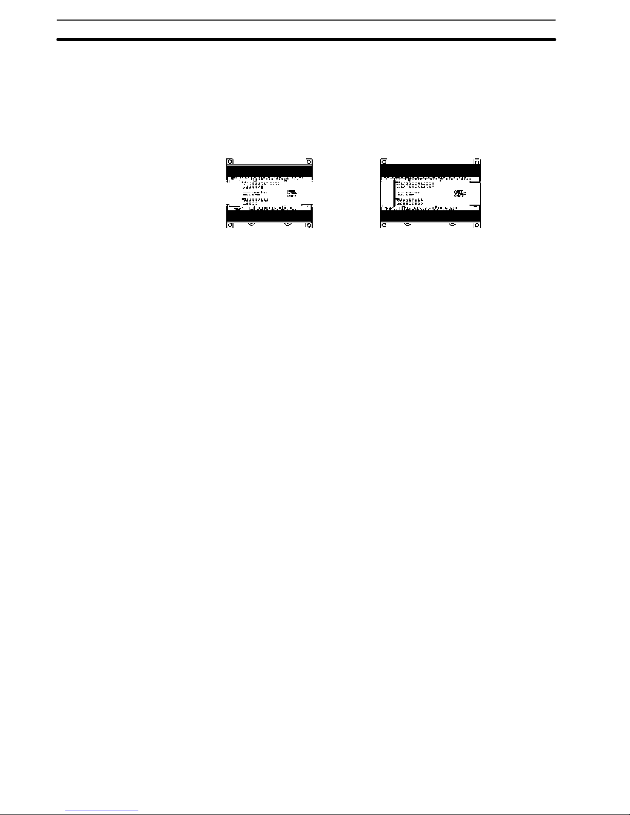
One- piece Construction The CPM1A CPU AC-Input Units feature a one-piece construction including 20,
or 32 built-in I/O terminals. These units are available in relay output models only.
CPM1A-20CAR-A
(20 I/O terminals)
Extra I/O Capacity Up to three Expansion I/O Modules can be connected to a CPM1A-32CAR-A
CPU Unit to add an extra 20 I/O points for each, for a maximum of up to 92 I/O
points.
Input Filter Function The CPM1A is equipped with a filter function to prevent incorrect operation
caused by chatter or noise in the input signal. The user can select an input time
constant of 1 ms, 2 ms, 4 ms, 8 ms, 16 ms, 32 ms, 64 ms, or 128 ms.
Low- maintenance Design Flash memory provides memory backup without a battery.
Input Interrupts The CPM1A-20CAR-A and CPM1A-32CAR-A CPU Units can handle 4 interrupt
inputs. In addition to normal input interrupts, the CPM1A has a counter mode
that counts high-speed input signals and triggers interrupts at fixed count multiples.
Quick- response Inputs Quick-response inputs can detect input signals with a pulse width as short as
5 ms regardless of their timing during the PLC cycle. Quick-response inputs and
interrupt inputs use the same input terminals.
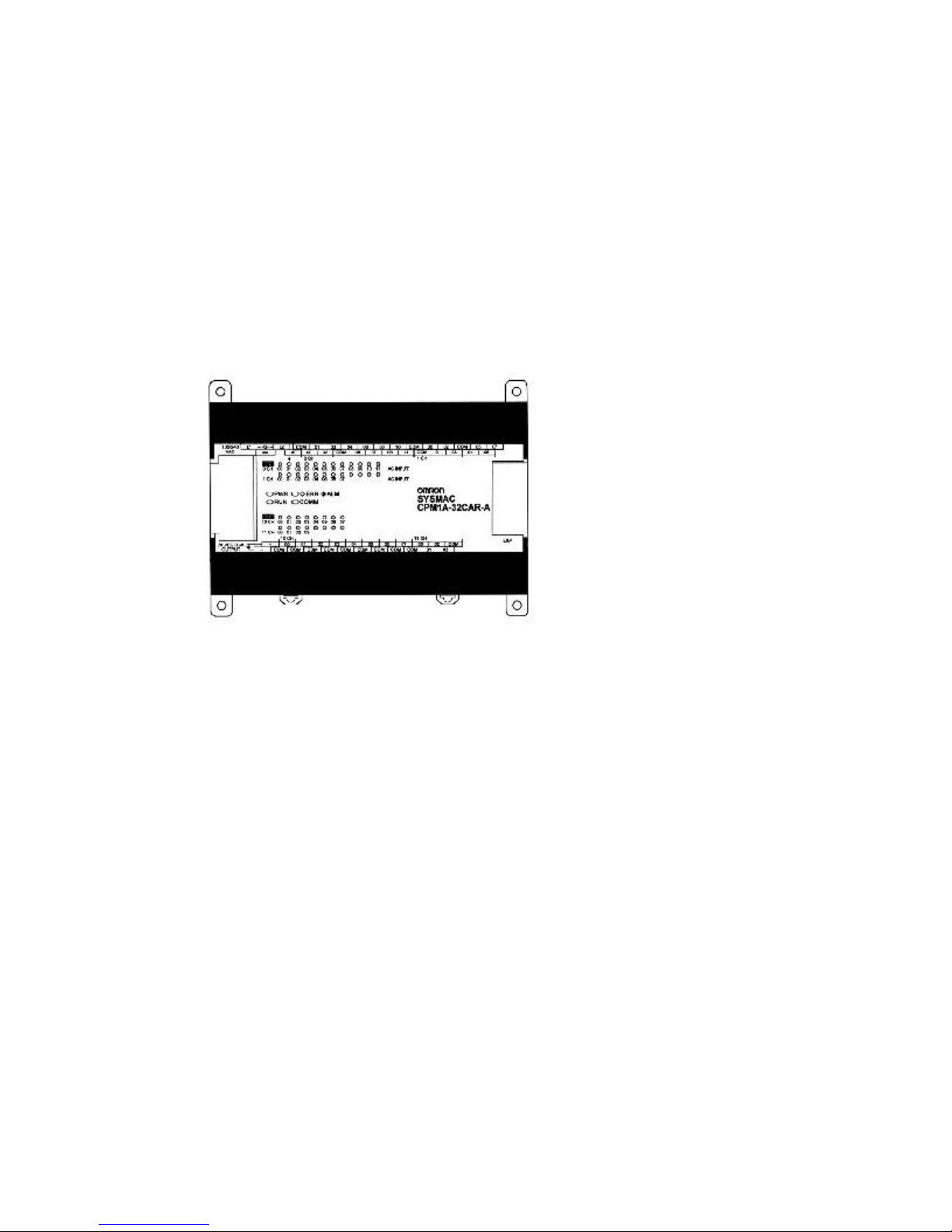
CPM1A-32CAR-A
(32 I/O terminals)
Interval Timer CPM1A PLCs have a high-speed interval timer which can be set from 5 ms to
319,968 ms. The timer can be set to trigger a single interrupt (one-shot mode) or
repeat scheduled interrupts (scheduled interrupt mode).
High- speed Counter CPM1A PLCs have a high-speed counter that can be used in incremental mode
or up/down mode. The high-speed counter can be combined with input interrupts to perform target value control or zone comparison control that isn’t affected by the PLC’s cycle time.
Analog Setting Function The CPM1A PLCs have 2 analog volume controls that can be used to make
manual analog settings.
Host Link Communications The CPM1A PLCs are compatible with the Host Link, which allows communica-
tions with personal computers. The CPM1A using the Host Link can also communicate with Programmable Terminal using host link commands.
An RS-232C Adapter is used for 1-to-1 communications and an RS-422 Adapter
is used for 1-to-n communications.
1- to-1 Link A data link can be created with a data area in another CPM1A, CQM1, CPM1,
SRM1 or C200HS or C200HX/HE/HG PLC. An RS-232C Adapter is used to
make the 1-to-1 connection.
NT Link Communications High-speed operations can be achieved by providing a direct access by con-
necting the CPM1A to the OMRON Programmable Terminal through the NT Link
Interface. An RS-232C Adapter is used for this connection.
Standard Peripheral Devices The CPM1A uses the same Programming Consoles and SYSMAC Support
Software (SSS) as the C200H/HS, C200HX/HE/HG, CPM1, SRM1, and CQM1
PLCs.
2

CPM1A Features and Functions Section 1- 1
Programming is Possible
Using the PT
Programming operation is possible through the PT screen by using an OMRON
PT that has a built-in Programming Console function.
1-1-2 I/O Terminal and IR Bit Allocation
The following table shows which IR bits are allocated to the I/O terminals on the
CPM1A’s CPU Units and Expansion I/O Module.
Number of I/O terminals on the CPU Unit 20 32
CPU Unit terminals Inputs 12 points:
00000 to 0001 1
Outputs 8 points:
01000 to 01007
CPM1A-20EDjExpansion I/OModule
Terminals
Power supply AC AC
Model number Relay output CPM1A-20CAR-A CPM1A-32CAR-A
Inputs --- 12 points:
Outputs --- 8 points:
Inputs --- 12 points:
Outputs --- 8 points:
Inputs --- 12 points:
Outputs --- 8 points:
20 points:
00000 to 0001 1
00100 to 00107
12 points:
01000 to 01007
01 100to 01 103
00200 to 0021 1
01200 to 01207
00300 to 0031 1
01300 to 01307
00400 to 0041 1
01400 to 01407
3
0000to020
0
CPM1A Features and Functions Section 1- 1
1-1-3 CPM1A Functions
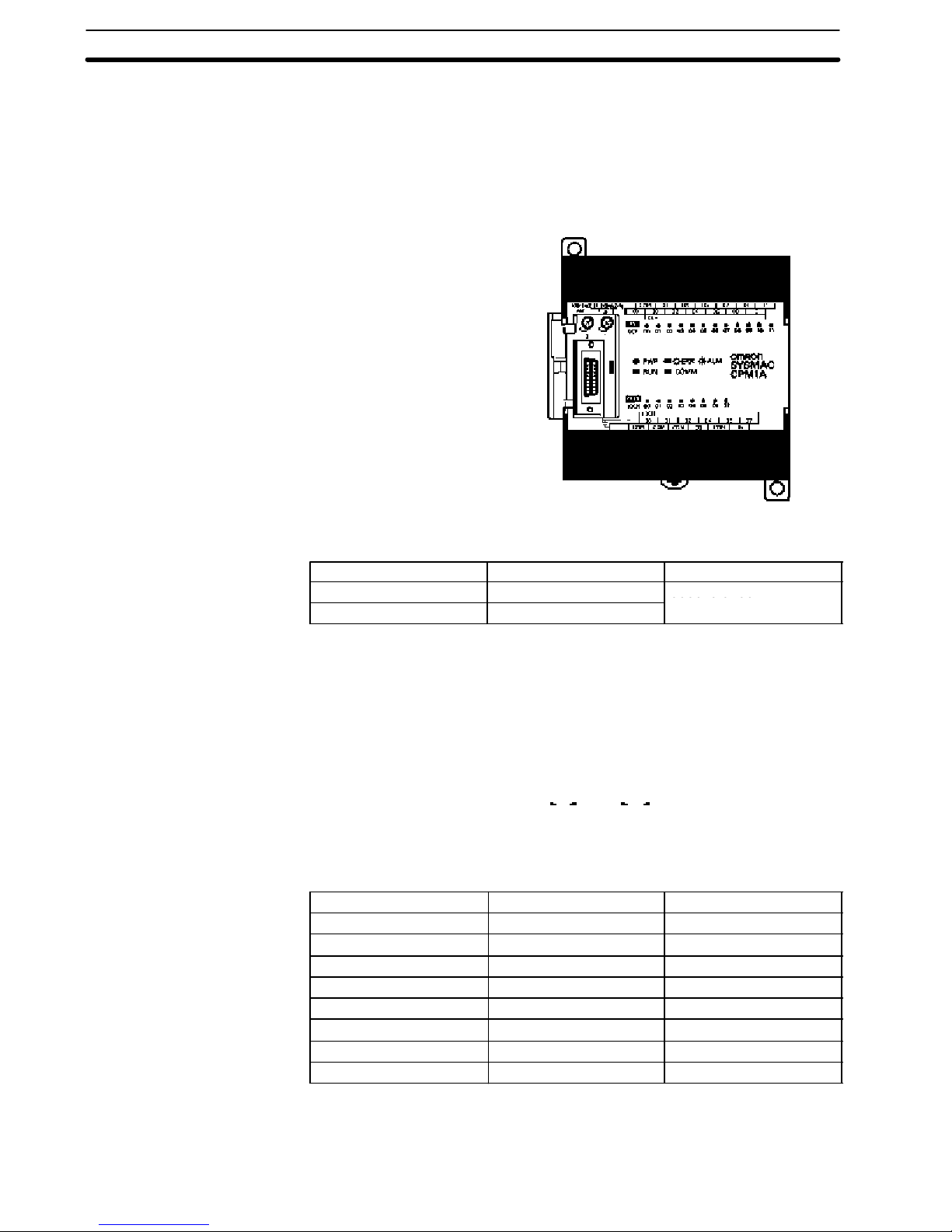
Analog Setting Function CPM1A PLCs have 2 variable-resistor adjustment knobs used to control analog
timer and counter settings manually. When one of the adjustments is turned, the
content of the corresponding IR word is set automatically between 0 and 200
(BCD).
Turn the adjustment knob with a Phillips screwdriver.
Analog adjustment 0
Analog adjustment 1
24 VDC 0.2 A
OUT PUT
The following table shows which IR words are allocated to the analog adjustments on the CPM1A’s CPU Unit.
Control Corresponding IR word Setting range (BCD)
Analog adjustment 0 IR 250 0000 to 0200
Analog adjustment 1 IR 251
Input Filter Function The input time constant for the CPM1A’s external inputs can be set to 1, 2, 4, 8,
16, 32, 64, or 128 ms. Increasing the input time constant can reduce the effects
of chatter or noise in the input signal. Typically, for AC inputs, the delay is set to
the default, 8 ms.
Inputfroman inputdevice
such as a limit switch
Input bit status
t
t
Input time constant
With the CPM1A, actual response time for each set input time constant
for word 000 is different from that for word 001 or later. See Set Value in the
following table.
Set value Word 000 Word 001 or later
1 ms 1 to 1.5 ms 0.3 to 0.4 ms
2 ms 2 to 2.5 ms 1.1 to 1.6 ms
4 ms 4 to 4.5 ms 2 to 3.5 ms
8 ms 8 to 8.5 ms 4.5 to 6.5 ms
16 ms 16 to 16.5 ms 9 to 13 ms
32 ms 32 to 32.5 ms 18 to 25 ms
64 ms 64 to 64.5 ms 37 to 50 ms
128 ms 128 to 128.5 ms 75 to 100 ms
The input response time of the CPM1A is obtained with the following:
4
2 ms max. (hardware performance) + input time constant (see above table)
+ cycle time
CPM1A-20CAR-AIR00003toIR000065m
s
CPM1A-20CAR-A
IR00003toIR000065ms
CPM1A Features and Functions Section 1- 1
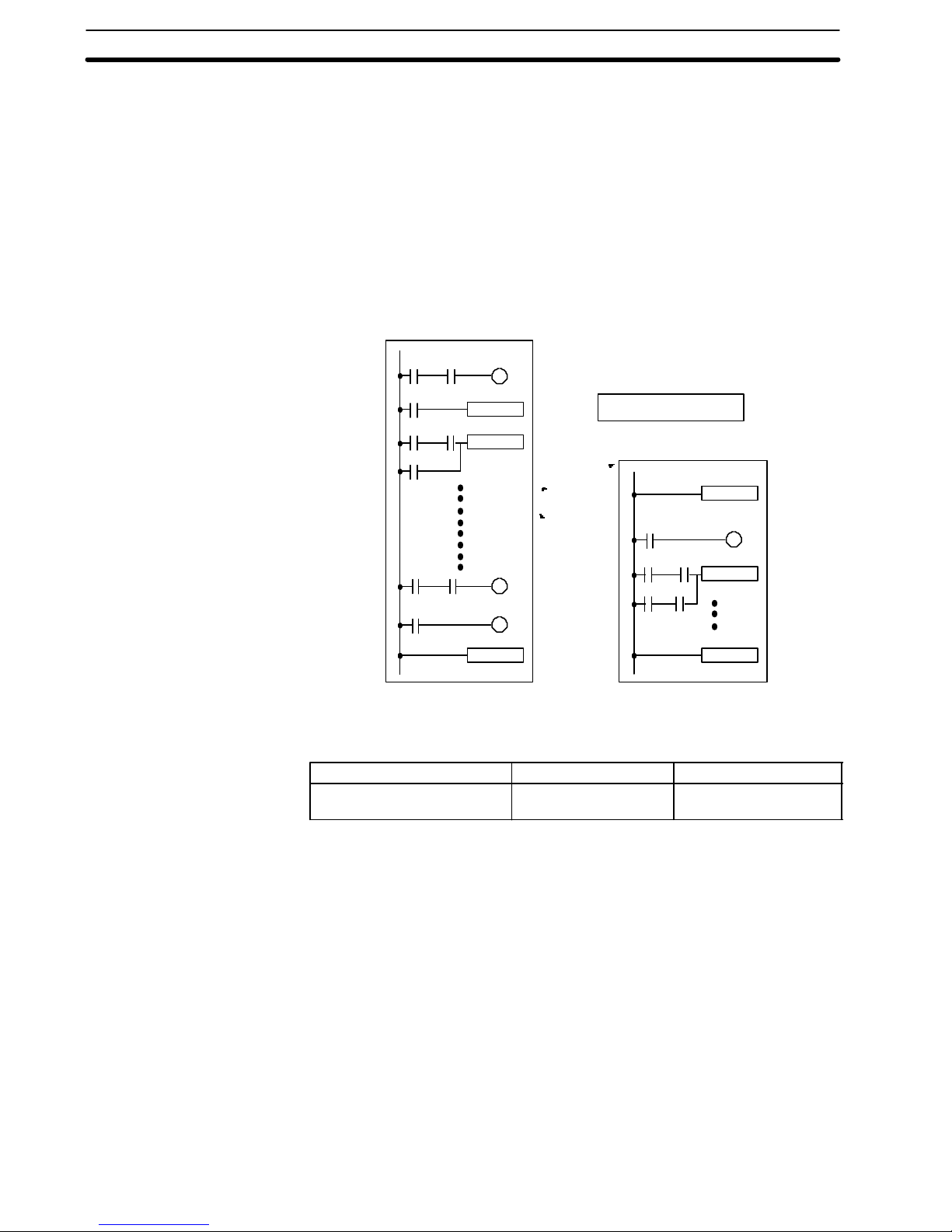
Input Interrupts The CPM1A-20CAR--A and CPM1A-32CAR--A have 4 interrupt input terminals.
There are two modes for input interrupts: input interrupt mode and counter
mode.
1, 2, 3... 1. When an interrupt occurs in Input Interrupt Mode, the main program is inter-
rupted and the interrupt program is executed immediately, regardless of the
cycle time.
2. In Counter Mode, external input signals are counted at high speed (up to
20 Hz) and an interrupt is generated each time the count reaches the set
value. When an interrupt occurs, the main program is interrupted and the
interrupt program is executed. The set value can be set from 0 to 65,535.
The following diagram shows the program execution when an interrupt occurs.
Main program
MOV
ADD
END
PLC model Input bits Response time
CPM1A-32CAR-A
Input interrupt
Interrupt program
SBN00
MOV
RET
(20 Hz in CounterMode)
Note When not using as interrupt input terminals, the input bits IR 00003 to IR 00006
can be used as normal input terminals.
5
CPM1A Features and Functions Section 1- 1
Quick- response Inputs The CPM1A-20CAR-A and CPM1A-32CAR-A PLCs have 4 quick-response in-
put terminals. (The same terminals are used for quick-response inputs and interrupt inputs.)
Quick-response inputs have an internal buffer , so input signals shorter than one
cycle can be detected.
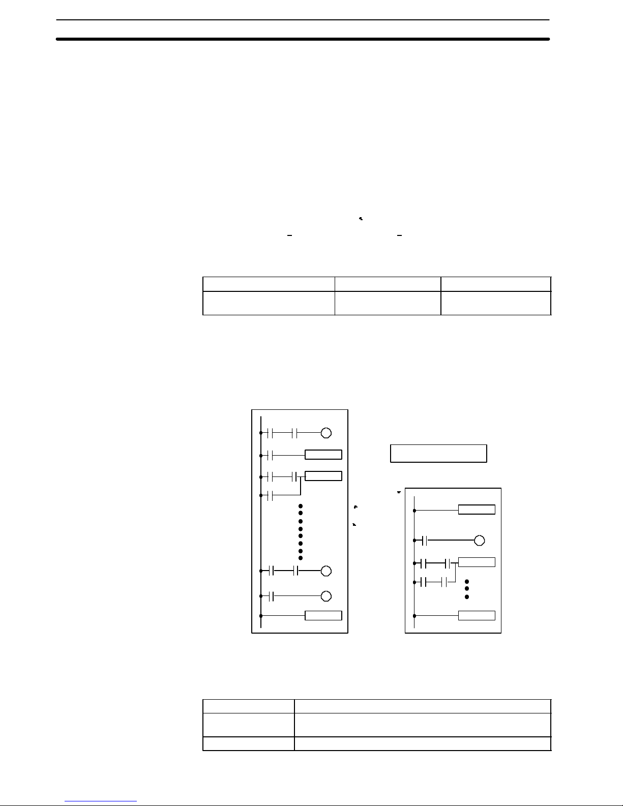
Interval Timer Function
(Scheduled Interrupts)
Input signal
(00003)
IR 00003
Overseeing
processes
Program
execution
Onecycle
I/O
refreshing
Overseeing
processes
Program
execution
I/O
refreshing
PLC model Input bits Min. input pulse width
CPM1A-20CAR-A
IR 00003 to IR 00006 5 ms
CPM1A-32CAR-A
CPM1A PLCs are equipped with an interval timer which can be set from 0.5 ms
to 319,968 ms in units of 0.1 ms. The timer can be set to trigger a single interrupt
(one-shot mode) or to trigger scheduled interrupts (scheduled interrupt mode).
Main program
MOV
ADD
END
Interval timer time-out
Interrupt program
SBN00
MOV
RET
Mode Function
One-shot Generates a single interrupt the first time that the timer times
out.
Scheduled interrupt Generates an interrupt each time that the timer times out.
6
CPM1A Features and Functions Section 1- 1
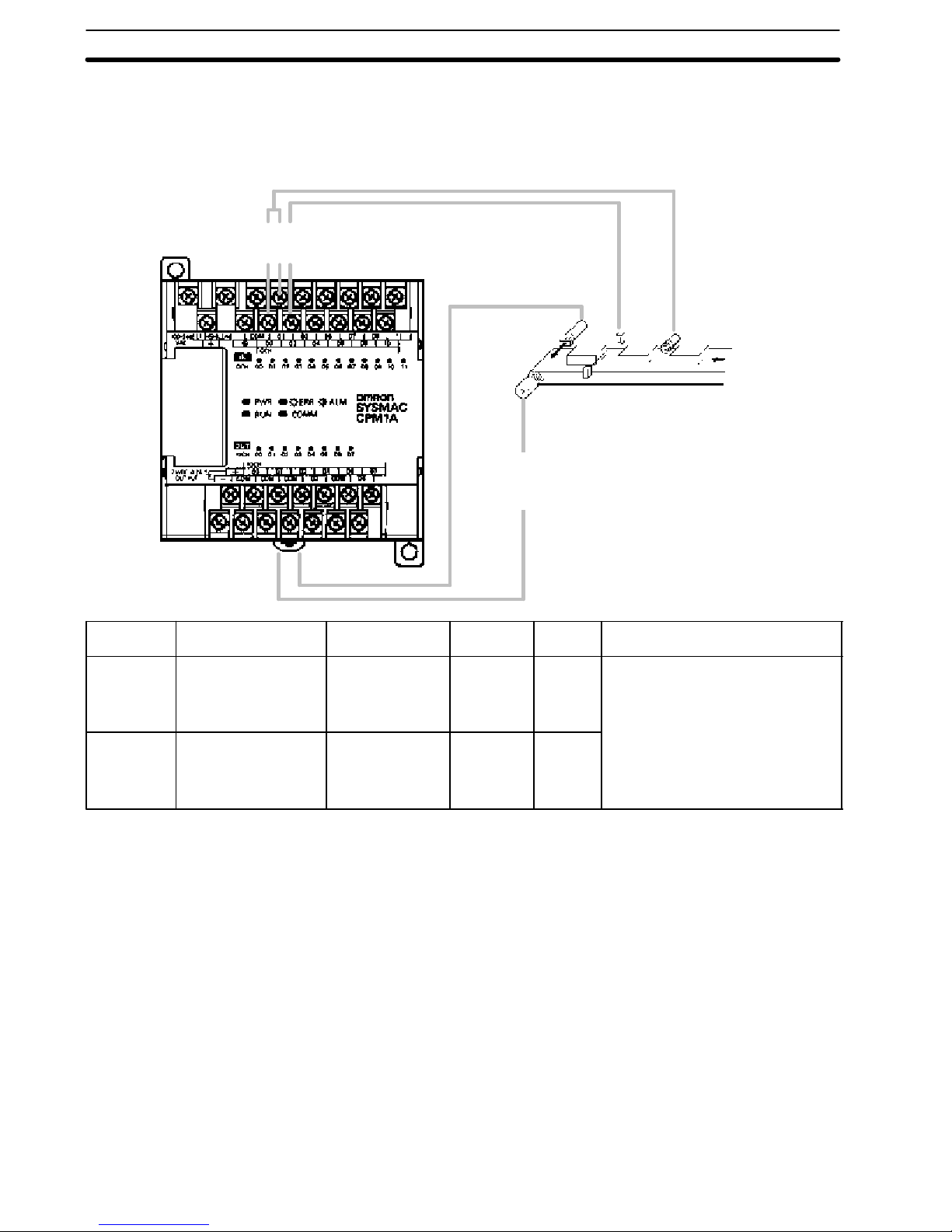
High- speed Counter CPM1A PLCs have a high-speed counter that can be used in incremental mode
or up/down mode. The high-speed counter can be combined with input interrupts to perform target value control or zone comparison control that isn’t affected by the PLC’s cycle time.
Count input
Reset input
00000
00001
00002
Solenoid
Sensor Rotary encoder
Motor
controller
Mode Input functions Input method Count
Up/Down 00000: A-phase input
00001: B-phase input
00002: Z-phase input
Incremental 00000: Count input
00001: See note.
00002: Reset input
Phase-difference,
4´ inputs
Individual inputs 20Hz 0
20 Hz --32767
Note In incremental mode, this input (00001) can be used as an regular input.
frequency
Count
range
to
32767
to
65535
Control methods
T argetvalue control:
Up to 16 target values and interrupt
subroutine numbers can be
registered.
Zone comparison control:
Up to 8 sets of upper limit values,
lower limit values, and interrupt
subroutine numbers can be
registered.
7
Numbero
f
InputsOutputsPowe
r
terminalsRelayoutpu
t
106DCpoints4point
s
2012DCpoints8points
3018DCpoints12point
s
4024DCpoints16point
s
Numbero
f
InputsOutputs
Relayoutput
System Configuration
1-2 System Configuration
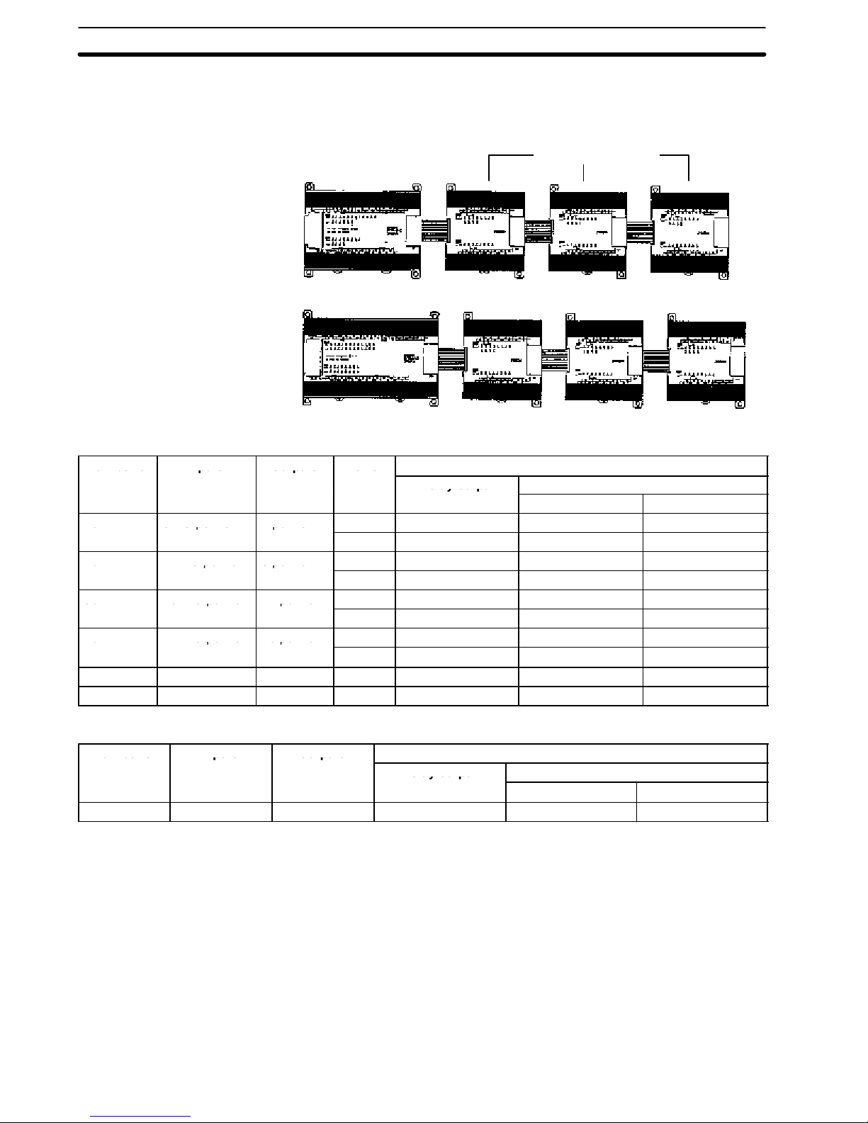
1-2-1 CPU Unit and Expansion I/O Module Configuration
Section 1- 2
CPM1A CPU Units
Expansion I/O Modules
CPM1A CPU Units
Number of
I/O
10 6 DC points 4 points AC CPM1A-10CDR-A --- ---
20 12 DC points 8points AC CPM1A-20CDR-A --- ---
30 18 DC points 12 points AC CPM1A-30CDR-A --- ---
40 24 DC points 16 points AC CPM1A-40CDR-A --- ---
20 12 AC points 8 points AC CPM1A-20CAR-A --- --32 20 AC points 12 points AC CPM1A-32CAR-A --- ---
Inputs Outputs Power
supply
DC CPM1A-10CDR-D CPM1A-10CDT -D CPM1A-10CDT1-D
DC CPM1A-20CDR-D CPM1A-20CDT -D CPM1A-20CDT1-D
DC CPM1A-30CDR-D CPM1A-30CDT -D CPM1A-30CDT1-D
DC CPM1A-40CDR-D CPM1A-40CDT -D CPM1A-40CDT1-D
Model number
Relay output T ransistoroutput
Sink type Source type
CPM1A Expansion I/O Module
Number of
I/O terminals
20 12 DC points 8 points CPM1A-20EDR CPM1A-20EDT CPM1A-20EDT1
Inputs Outputs Model number
8
Relay output T ransistoroutput
Sink type Source type
System Configuration
Section 1- 2
1-2-2 Host Link Communications
Host Link communications which allows up to 32 OMRON PLCs to be controlled
from a host computer .The computer-PLC connections can be made connectors
such as RS-232C and RS-422 Adapters.
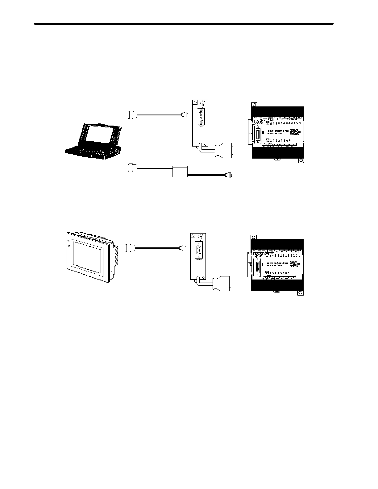
1- to-1 Communications The following diagram shows the possible methods for a 1-to-1 connection be-
tween a CPM1A and an IBM PC/AT or compatible computer .
IBM PC/A T or
compatible
Connecting to a
Programmable Terminal
OMRON Programmable Terminal
RS-232C Adapter
RS-232C Cable
CPM1-CIF01
CQM1-CIF02
CPM1A CPU Unit
The following diagram shows the possible methods for a connection between a
CPM1A PLC and an OMRON Programmable Terminal (a operator interface device).
RS-232C Adapter
RS-232C Cable
CPM1A CPU Unit
CPM1-CIF01
9

Convertstoperipheralport-leve
l
System Configuration
Section 1- 2
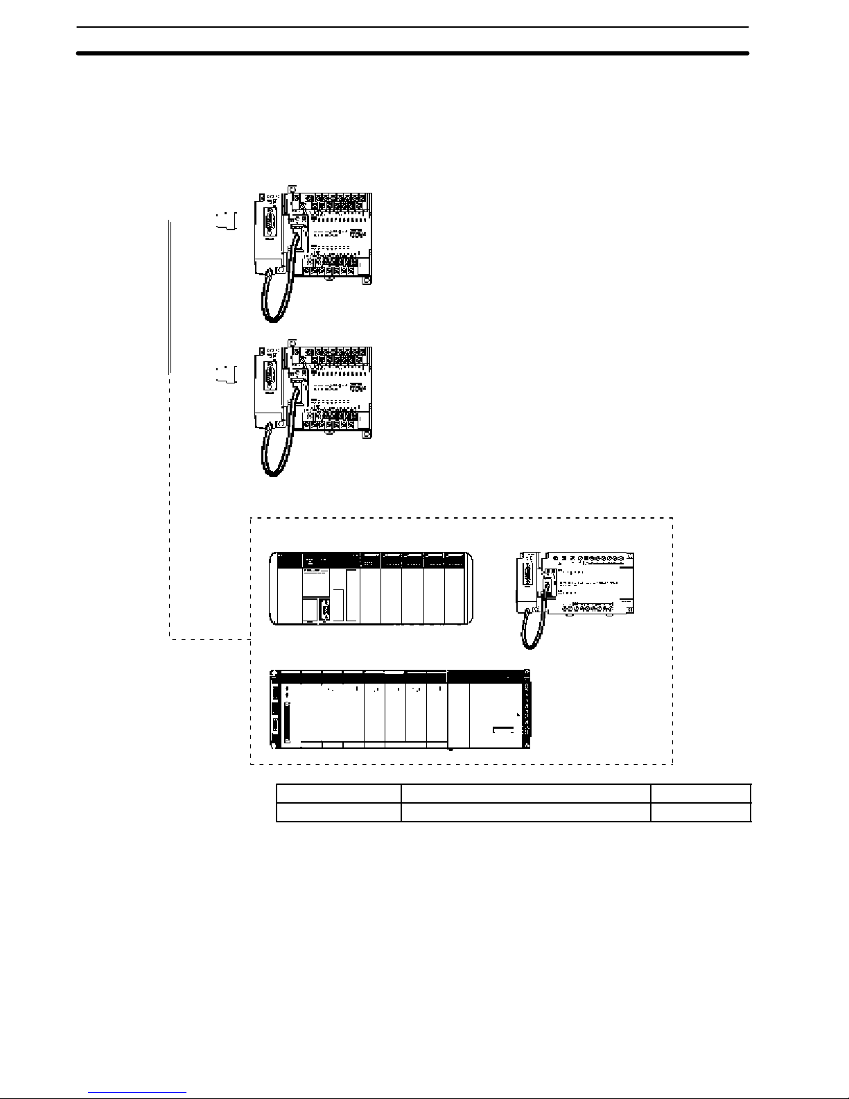
1- to-n Communications The following diagram shows how to connect up to 32 CPM1A PLCs to an IBM
PC/AT or compatible computer .
IBM PC/A T or compatible
CPM1-CIF1 1
3G2A9-AL004-E
Link Adapter
RS-232C Cable
RS-422 Cable
RS-422
Adapters
CPM1A CPU Units
The maximum cable length of RS-422 should be 500 m.
Adapters and Cables The following table lists some of the Adapters and Cables used in Host Link com-
munications.
RS-232C Adapter Converts to peripheral port-level
RS-422 Adapter
Connecting Cables Used to connect IBM PC/AT or
Link Adapter Converts between the RS-232C and
10
OMRON CPM1A
PLCs (32 PLCs max.)
Name Usage Model number
communications.
compatible computers.
(Cable length: 3.3 m)
RS-422 formats.
CPM1-CIF01
CPM1-CIF11
CQM1-CIF02
3G2A9-AL004-E
System Configuration
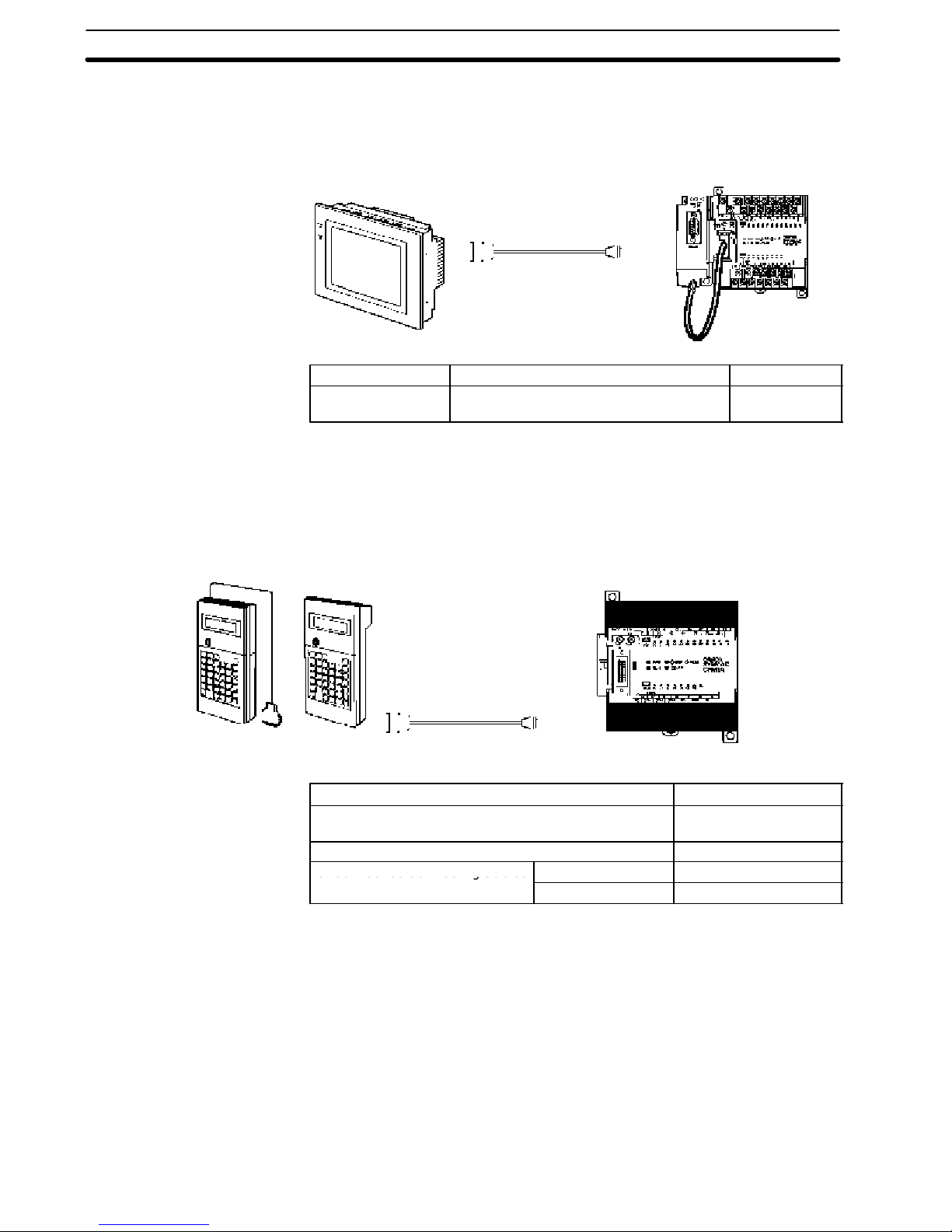
1-2-3 1-to-1 Communications Links
A data link can be created with a data area in another CPM1A, CQM1, CPM1,
SRM1 or C200HS PLC or a C200HX/HE/HG PLC. An RS-232C Adapter is used
to make the 1-to-1 connection.
CPM1A CPU UnitsRS-232C Adapters
RS-232C Cable
Section 1- 2
CQM1 CPM1 + RS-232C Adapter
C200HS/C200HX/HG/HE
Name Usage Model number
RS-232C Adapter Converts to the Peripheral Port format. CPM1-CIF01
11
C200H-seriesConnectingCable
s
System Configuration
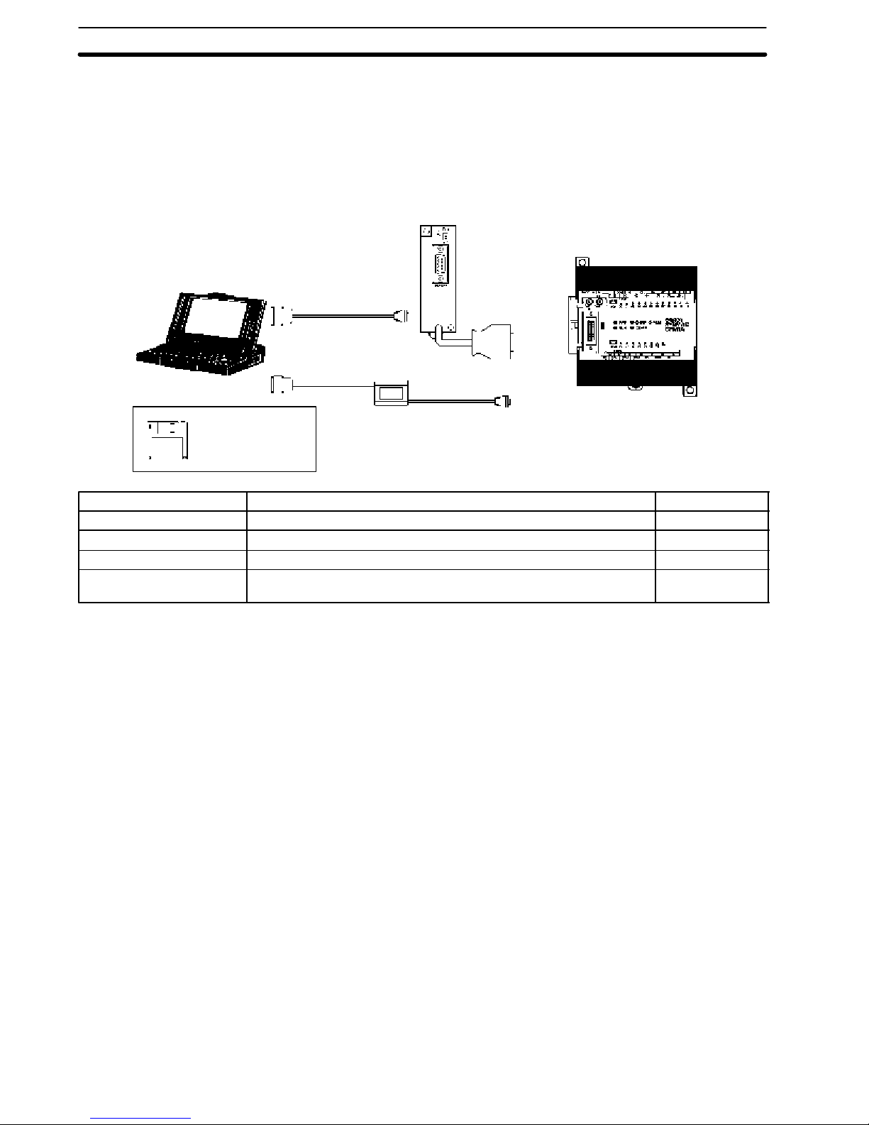
1-2-4 NT Link Communications
Using the NT Link, the CPM1A PLC can be connected to the Programmable Terminal (NT Link Interface) through an RS-232C Adapter .
Section 1- 2
OMRON Programmable Terminal
RS-232C Cable
Name Usage Model number
RS-232C Adapter Converts to peripheral port-level
communications.
RS-232C
Adapter
CPM1A CPU Unit
CPM1-CIF01
1-2-5 Peripheral Device Connections
CPM1A programs can be created or edited with a Programming Console or a
personal computer running SYSMAC Support Software (SSS).
Programming Consoles A CQM1-PRO01-E or C200H-PRO27-E Programming Console can be con-
nected to the CPM1A as shown in the following diagram.
CPM1A CPU Unit
CQM1-PRO01-E C200H-PRO27-E
CQM1 Programming Console
(The Connecting Cable is included.)
C200H/HS and C200HX/HE/HG Programming Console C200H-PRO27-E
C200H-seriesConnectingCables Cable length: 2 m C200H-CN222
C200H-CN222
Name Model number
CQM1-PRO01-E
Cable length: 4 m C200H-CN422
12
System Configuration
Section 1- 2
SYSMAC Support Software
and SYSMAC- CPT Support
Software
IBM PC/A T or compatible
SSS,
SYSMAC-CPT
An IBM PC/AT or compatible personal computer running SSS or the SYSMACCPT Support Software can be connected to the CPM1A as shown in the following diagram. Refer to NO TAG Host Link Connections for a diagram showing the
standard wiring for the RS-232C cable.
Any version of the Support Software may be used. Refer to NO TAG Support
Software Capabilities for further details on installing and using Support Software.
RS-232C Adapter
CPM1A CPU Unit
RS-232C Cable
CQM1 -CIF02
Name Usage Model number
RS-232C Adapter Converts to Peripheral Port format level communications. CPM1-CIF01
Connecting Cable Used to connect IBM PC/AT or compatible computers. (Length: 3.3 m) CQM1-CIF02
SYSMAC SupportSoftware For IBM PC/AT or compatible computers (3.5” disks, 2HD) C500-ZL3AT1-E
SYSMAC-CPT Support
Software
For IBM PC/AT or compatible computers
(3.5” disks (2HD) and CDROM)
WS01-CPTB1-E
13

System Configuration
Section 1- 2
14

SECTION 2
Unit Specifications and Components
ThissectionprovidesthetechnicalspecificationsoftheModulesthatgotogethertocreatea CPM1A PLCand describesthe
main components of the Modules.
2-1 Specifications 16. . . . . . . . . . . . . . . . . . . . . . . . . . . . . . . . . . . . . . . . . . . . . . . . . . . . . . . . .
2-1-1 General Specifications 16. . . . . . . . . . . . . . . . . . . . . . . . . . . . . . . . . . . . . . . . . . . .
2-1-2 Characteristics 17. . . . . . . . . . . . . . . . . . . . . . . . . . . . . . . . . . . . . . . . . . . . . . . . . .
2-1-3 I/O Specifications 19. . . . . . . . . . . . . . . . . . . . . . . . . . . . . . . . . . . . . . . . . . . . . . .
2-1-4 Communications Adapter Specifications 23. . . . . . . . . . . . . . . . . . . . . . . . . . . . . .
2-2 Unit Components 24. . . . . . . . . . . . . . . . . . . . . . . . . . . . . . . . . . . . . . . . . . . . . . . . . . . . . .
2-2-1 CPU Unit Components 24. . . . . . . . . . . . . . . . . . . . . . . . . . . . . . . . . . . . . . . . . . .
2-2-2 Expansion I/O Module Components 26. . . . . . . . . . . . . . . . . . . . . . . . . . . . . . . . .
2-2-3 Communications Adapter Components 27. . . . . . . . . . . . . . . . . . . . . . . . . . . . . . .
16
 Loading...