

© 2010 Syslogic Datentechnik AG www.syslogic.com Page 1 of 4
Version 2.0
| July 2010 All rights reserved
Product specifications subject to change without notice. | All data is for information purposes only and not guaranteed for legal purposes. Information in this data sheet has been carefully checked and is believed to be accurate. However, no responsibility is assumed for inaccuracies.
Document order code: DOC/PANxxxIS-INST
Deutsch
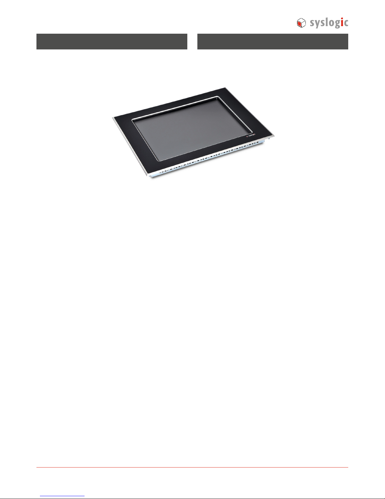
Montage Anweisung
Infrarot Touch Panel Display
TFT/PANxxxIS-F1
Sicherheitshinweise
Allgemeine Hinweise
Zur Gewährleistung eines sicheren Betriebes darf das Gerät
nur nach den Angaben in der Betriebsanleitung betrieben
werden. Bei der Verwendung sind zusätzlich die für den
jeweiligen Anwendungsfall erforderlichen Rechts- und Sicherheitsvorschriften zu beachten. Sinngemäss gilt dies auch bei
Verwendung von Zubehör.
Bestimmungsgemässe Verwendung
Das Gerät ist für den industriellen, stationären Einsatz konzipiert. Jeder darüber hinaus gehende Gebrauch gilt als nicht
bestimmungsgemäss.
Qualifiziertes Personal
Die Displays dürfen nur von qualifiziertem Personal installiert, eingesetzt und bedient werden unter Einhaltung der
technischen Bestimmungen. Qualifiziertes Personal ist definiert als Personen, die im Umgang mit diesem Gerät vertraut
sind und über die benötigten Ausbildungen und Erfahrungen
für den Umgang mit dem Gerät verfügen.
Restgefahren
Die Displays entsprechen dem Stand der Technik und sind
betriebssicher. Von den Geräten können Restgefahren ausgehen, wenn sie von ungeschultem Personal unsachgemäss
eingesetzt und bedient werden.
Benutzerdokumentation
Die Benutzerdokumentation des TFT–Panel erhalten Sie auf
Anfrage oder als Download unter www.syslogic.com
(Document order code: DOC/PANxxxIS-F1E)
English
Installation guide
Infrared touch panel display
TFT/PANxxxIS-F1
Safety information
General information
In order to ensure safe operation, the device may only be
operated in accordance to the specifications stated in this
operation manual. Furthermore, all legal and safety regulations concerning this specific application should be observed.
This also applies to the use of accessories.
Correct use to the independent purpose
The device is designed for industrial, stationary use. All other
forms of usage do not comply with the intended purpose.
Qualified staff
The Displays may only be installed, connected, set-up and
operated by qualified staff and in compliance with technical
specifications. Qualified staff is defined as persons, who are
familiar with set-up, mounting, start-up and operation of this
device and who posses a recognized degree or certificate of
appropriate professional training.
Remaining hazards
These Displays employ state-of-the-art technology and safe
operate. However, if they are installed and operated by
unqualified staff, an element of risk remains.
User documentation
You will get a detailed user documentation on request or as
download. Please visit www.syslogic.com
(Document order code: DOC/PANxxxIS-F1E)

© 2010 Syslogic Datentechnik AG www.syslogic.com Page 2 of 4
Version 2.0
| July 2010 All rights reserved
Product specifications subject to change without notice. | All data is for information purposes only and not guaranteed for legal purposes. Information in this data sheet has been carefully checked and is believed to be accurate. However, no responsibility is assumed for inaccuracies.
Document order code: DOC/PANxxxIS-INST
Lieferumfang
Verpackung
Standard Zubehör
TFT Panel
Konterrahmen
10.4", 12.1", 15" Versionen 19" Version
1x TFT-Panel 1x TFT-Panel
1x Dichtung 1x Dichtung
1x Power Supply Stecker 1x Power Supply Stecker
4x Befestigungsmuttern 8x Befestigungsmuttern
1x Konterrahmen 1x Konterrahmen
Installationshinweise und Inbetriebnahme
Montage
Das TFT-Panel von vorne in den Ausschnitt der Fronttafel 1.
schieben.
Die Frontdichtung muss zwischen Frontplatte und Front-2.
tafel flach und rundum gleichmässig aufliegen.
Das Gerät im Ausschnitt zentrieren.3.
Das Gerät mit dem mitgelieferten Befestigungsrahmen 4.
von der Rückseite her gleichmässig mit den 4 oder 8
Sicherungsmuttern festschrauben (maximal bis der Frontrahmen umlaufend an der Fronttafel anliegt.)
Achten Sie auf einwandfreien Sitz der Dichtungen an der •
Fronttafel. Bei Geräten mit Runddichtung müssen die beiden Enden der Dichtung an der Geräteunterseite bündig
montiert werden.
Vermeiden Sie Drehmomente >0.5Nm, das Gerät könnte •
sonst beschädigt werden.
Die Fronttafel darf eine maximale Dicke von 5mm nicht •
überschreiten.
Zur Vermeidung einer Überhitzung des Gerätes während
dem Betrieb ist folgendes zu beachten:
Allfällige Kühlschlitze müssen frei sein, um die System-•
kühlung zu gewährleisten
Vermeiden Sie die direkte Sonneneinstrahlung auf die •
Front
Der Neigungswinkel zum senkrechten Einbau darf max. ± •
35° betragen.
Included in delivery
Packing
Standard accessory
TFT Panel
Fixing frame
10.4", 12.1", 15" Versions 19" Version
1x TFT-Panel 1x TFT-Panel
1x Seal 1x Seal
1x Power supply connector 1x Power supply connector
4x Securing nuts 8x Securing nuts
1x Fixing frame 1x Fixing frame
Installation instructions and operation
Mounting
Push the TFT-Panel from the front into the cutout of the 1.
front panel.
The front seal must be level and evenly positioned bet-2.
ween the front plate and the front panel.
Centring the device in the cutout3.
Secure the device from the rear with the supplied fixing 4.
frame. For this use 4 or 8 securing nuts which should be
tightened evenly from the rear until the front frame is
flush with the front panel all round.
Ensure that the seal is fitted correctly on the front panel. •
For devices with a round seal the two ends must be at the
lower side of the device and should fit together without a
gap.
Avoid tightening torques of greater than 0.5Nm as this •
could otherwise damage the device.
The thickness of the front panel must not exceed 5mm.•
The following must be ensured in order to prevent the
device from overheating during operation:
The cooling slots must always be free in order to ensure •
the proper cooling of the system.
Avoid the exposure of the flat screen to direct sunlight.•
The mounting angle must not exceed ± 35° from the •
vertical, if these conditions cannot be met, the mounting
of an external fan is recommended.

© 2010 Syslogic Datentechnik AG www.syslogic.com Page 3 of 4
Version 2.0
| July 2010 All rights reserved
Product specifications subject to change without notice. | All data is for information purposes only and not guaranteed for legal purposes. Information in this data sheet has been carefully checked and is believed to be accurate. However, no responsibility is assumed for inaccuracies.
Document order code: DOC/PANxxxIS-INST
Anschlüsse
Verbindungen zwischen Syslogic COMPACT – IPC und
TFT-Panel:
Der COMPACT-IPC muss mit einem DVI Anschluss 1.
ausgerüstet sein.
DVI Kabel am COMPACT IPC und TFT-Panel anschliessen 2.
Touch Kabel am COPMPACT IPC und TFT-Panel 3.
anschliessen
24VDC Stromversorgung anschliessen4.
Schnittstellen
An nachfolgende Schnittstellen angeschlossene Kabellei-•
tungen sind von niederspannungsführenden Leitungen
getrennt zu verlegen
Für einen störungsfreien Betrieb müssen Kabel aus dem •
Originalzubehör verwendet werden. (Siehe Benutzerdokumentation)
Touch – Anschluss
Pin Signal Beschreibung
1 - Reserviert
Touch
2 RXD Empfangssignal für den Touch
3 TXD Sendesignal des Touch
4 - Reserviert
5 GND
6 - Reserviert
7 - Reserviert
DSUB9 male
8 - Reserviert
9 - Reserviert
TFT/PANxxxIS
4
+
1
2
V
D
C
3
1
2
DVI
T
ouch
Power supply
Touch (RS232)
Digital Video DVI
Syslogic
COMPACT IPC
Connections
Connections between a TFT-Panel and a
Syslogic COMPACT-IPC:
The COMPACT-IPC must have a DVI port1.
Connect DVI cable between the COMPACT-IPC and the 2.
TFT-Panel
Connect the touch cable between the COMPACT-IPC 3.
(COM2) and the TFT-Panel
Connect 24VDC power supply4.
Interfaces
Cables connected to the following interfaces must be laid •
separately from the low-voltage cables.
To ensure disturbance-free operation, it is strongly recom-•
mended to use cables from the original accessories. (see
documentation)
Touch connection
Pin Signal Description
1 - reserved
Touch
2 RXD Received signal Touch screen
3 TXD Send signal Touch screen
4 - reserved
5 GND
6 - reserved
7 - reserved
DSUB9 male
8 - reserved
9 - reserved

© 2010 Syslogic Datentechnik AG www.syslogic.com Page 4 of 4
Version 2.0
| July 2010 All rights reserved
Product specifications subject to change without notice. | All data is for information purposes only and not guaranteed for legal purposes. Information in this data sheet has been carefully checked and is believed to be accurate. However, no responsibility is assumed for inaccuracies.
Document order code: DOC/PANxxxIS-INST
Power Supply Anschluss 24VDC
Das TFT-Panel ist ein Gerät der Schutzklasse 3. Die Systemversorgung hat mit Sicherheitskleinspannung SELV 24VDC
(safety extra-low voltage) zu erfolgen. Die Versorgung ist
nicht galvanisch getrennt.
Pin Signal Beschreibung
1 24VDC 24VDC Power Supply
1 2 3
2 - Reserviert
Phoenix 3pol male
3 0V 0V Power Supply (verbunden mit GND)
DVI-Schnittstelle
Die DVI-Schnittstelle entspricht dem Single Link DVI-D
Standard.
Frontplatten Ausschnitt / Abmessungen
Ausschnitt [mm]
1
Abmessungen [mm]
Produkt A B BxHxT
TFT/PAN104IS 329 +0/-1 238 +0/-1 345 x 260 x 64 (10.4 Zoll)
TFT/PAN121IS 344 +0/-1 262 +0/-1 361 x 279 x 63 (12.1 Zoll)
TFT/PAN150IS 410 +0/-1 315 +0/-1 427 x 332 x 63 (15 Zoll)
TFT/PAN190IS 495 +0/-1 403 +0/-1 512 x 420 x 64 (19 Zoll)
1
Details gemäss Benutzerdokumentation
Entsorgung
Nicht mehr benutzte TFT-Panel müssen ordnungsgemäss •
entsorgt oder zur Entsorgung zum Hersteller zurück
gesandt werden. (weitere Informationen finden Sie in der
Benutzerdokumentation)
Nicht mehr benötigte Verpackungen müssen ordnungs-•
gemäss entsorgt oder zur Entsorgung an den Hersteller
oder Vertrieb retourniert werden. Die Verpackung besteht
aus folgenden Materialien:
Schachtel aus Karton, Transportschutz und Kunststoffbeutel aus TFL Schaumstoff (Polyethylen).
Kontakt und technischer Support
Syslogic Datentechnik AG, Baden-Dättwil, Schweiz
Tel +41 56 200 90 40
| Fax +41 56 200 90 50
info@syslogic.ch
| support@syslogic.ch
Power supply connection 24VDC
The TFT-Panel device belongs to protection class 3. The
system power supply must be provided with a 24VDC SELV
voltage. The power supply is not isolated.
Pin Signal Description
1 24VDC 24VDC Power supply
1 2 3
2 - reserved
Phoenix 3pol male
3 0V 0V Power supply (connected to GND)
Digital Video Interface
The Digital Video Interface is compatible to the Single Link
DVI-D Standard.
Front cutout / dimensions
Cut out [mm]
1
Dimesions [mm]
Product A B WxHxD
TFT/PAN104IS 329 +0/-1 238 +0/-1 345 x 260 x 64 (10.4 Zoll)
TFT/PAN121IS 344 +0/-1 262 +0/-1 361 x 279 x 63 (12.1 Zoll)
TFT/PAN150IS 410 +0/-1 315 +0/-1 427 x 332 x 63 (15 Zoll)
TFT/PAN190IS 495 +0/-1 403 +0/-1 512 x 420 x 64 (19 Zoll)
1
for details see user documentation
Disposal
TFT-Panel devices that are no longer used must be fairly •
disposed or returned to the manufacturer for disposal.
(Further information you will find in the device user
documentation)
Packaging not needed anymore must be fairly disposed •
or returned to the manufacturer or distributor for
disposal.
The wrapping contains the following materials:
Cardboard box, transportation protection and bag made
of TFL-foam (Polyethylene).
Contact and technical support
Syslogic Datentechnik AG, Baden-Dättwil, Switzerland
Phone +41 56 200 90 40
| Fax +41 56 200 90 50
info@syslogic.ch
| support@syslogic.ch
 Loading...