

SysKonnect SK-9Exx, SK-9Sxx User Manual

SysKonnect
SK-9Exx/9Sxx
User Manual
SK-9Exx and SK-9Sxx Gigabit Ethernet Server Adapters


SysKonnect SK-9Exx and SK-9Sxx
Gigabit Ethernet Server Adapters
User Manual
(v1.00 / 4 January, 2005)
Visit our web site: http://www.syskonnect.com
SysKonnect SK-9Exx/9Sxx Gigabit Ethernet Server Adapters

4
Copyright © SysKonnect GmbH, 2004. All rights reserved.
This manual refers to the adapters of the SysKonnect SK-9Exx/9Sxx Gigabit Ethernet Adapter Family. It describes the hardware and software installation and the functionality of the adapters.
Contents are subject to change. Product and brand names are (registered) trademarks of their appropriate owners.
Please send your comments on this documentation to:
SysKonnect GmbH
A Marvell®Company
Information Development
Siemensstraße 23
76275 Ettlingen / Germany
Fax: +49 7243 502 989
E-Mail: manual@syskonnect.de
German and French versions of this manual are available on the SysKonnect installation CD-ROM
and on our web site.

Conventions
The following conventions apply to this manual.
Warnings and Notes
Used to indicate a potentially hazardous situation which, if not avoided, could result in death or serious injury. Example: dangerous voltage.
Used to indicate a potentially hazardous situation which, if not avoided, may result in minor or moderate injury. Example: electrostatic discharge.
i
Used for additional information and advice.
Font Styles applied
Italics: Italics is used for the following elements:
• In bodytext as an introduction of new technical terms
• In instructions for radio buttons and check boxes
Examples: The station is operated in Repeater Mode.
Select the Sharing radio button.
Select the Enable Bidirectional Support check box.
S
MALL CAPS:SMALL CAPS is used for the following elements:
• Menu options
• Buttons
•Tabs
• Entries in a list box
Examples: In the main menu, select E
Click the C
Select the tab P
The top line in the printer list (HP L
the HP laserjet printer 4M is installed on this PC.
ONNECT button.
ORTS.
XIT.
ASERJET 4M) indicates that
Quotation
Marks (“ ”)
SysKonnect SK-9Exx/9Sxx Gigabit Ethernet Server Adapters
Quotation Marks are used for the following elements:
• Window/screen names
• Field names
• List box names
Examples: The “Create NDPS Manager Object” window is displayed.
Type a name in the field “NDPS Manager Name”.
The list “Network” is displayed, containing all installed network
components.

6 Conventions
Courier: Courier is used for the following elements:
• Terminal input to be entered by the user
• Terminal output issued by the system
Examples: Enter sk98diag.
If the test was successful, the message passed is issued.
Underline
Underline is used to identify hyperlinks.
Example: Visit our web site:http://www.syskonnect.com
.

Table of Contents
Conventions 5
Warnings and Notes 5
Font Styles applied 5
Safety Precautions 11
Avoiding injuries 11
Avoiding damage 11
1 Installation of the Network Adapter 13
2 Connection of the Network Adapter 15
Transmission Distances 15
Connection to the Network 15
3 Installation of the Driver Software 17
Windows 18
Windows NT 4.0 18
Windows 98 Second Edition 19
Windows Millennium Edition 19
Windows 2000 20
Windows XP and Windows Server 2003 21
Linux 21
4 Hardware Features 23
Adapter Characteristics 24
SysKonnect SK-9Exx Adapters (PCI Express) 24
SysKonnect SK-9Sxx Adapters (PCI/PCI-X) 24
LED Displays 25
5 Software Features 27
Operating System Support 27
High Performance 27
TCP, UDP and IP Checksum Calculation 27
Jumbo Frames 27
TCP Segmentation (Large Send Off-Load) 27
Dynamic Interrupt Moderation 27
Promiscuous Mode / Multicast Support 27
PXE / RPL Support 28
Advanced Power Management / Wake on LAN 28
Reliability 28
Hot-Plug 28
Parity 29
Sensors 29
User Diagnostics (DOS) 29
Virtual LAN (VLAN) support 29
6 Testing the Network Adapter 31
Diagnostics Program 31
Loopback Wrap Plug Test 31
Loopback Repeater Test 33
Failure of a Test 34
SysKonnect SK-9Exx/9Sxx Gigabit Ethernet Server Adapters

8 Table of Contents
Additional Functions of the Diagnostics Program 35
Checking Other Displays and Data 35
Starting the Main Program 35
Reading Sensor Data 36
Reading Configuration Data 36
Reading Vital Product Data (VPD) 37
Sample Usage of VPD / Asset Tag 38
7 Troubleshooting 41
8 Important Information 43
Technical Support 43
Returning an Adapter for Repair 43
Additional Documentation and Updates 44
Technical Specifications 45
How to Identify your Network Adapter Type 47
Appendix A. License and Warranty Information 49
The Americas, Asia, Australia, New Zealand, Pacific 49
Europe 50
Deutschland, Schweiz, Österreich, Liechtenstein 51

Table of Figures
Figure 1: Insertion of the adapter into the computer 14
Figure 2: Connection of fiber-optics cables/plugs 16
Figure 3: Possible network configurations / connection options 23
Figure 4: Location of the LEDs (adapter variant 1) 25
Figure 5: Location of the LEDs (adapter variant 2) 26
Figure 6: Setup for loopback wrap plug testing 31
Figure 7: Typical display after a successful test (loopback wrap plug) 32
Figure 8: Typical error message from the diagnostics program 34
Figure 9: Diagnostics program, main menu 35
Figure 10: Display of configuration data 37
Figure 11: VPD menu 37
Figure 12: Display of VPD 38
Figure 13: Screen showing updated asset tag 39
SysKonnect SK-9Exx/9Sxx Gigabit Ethernet Server Adapters

10 Table of Figures

i
Safety Precautions
To protect yourself from injuries and avoid damage of the device, always observe the following safety instructions when installing the network adapter.
Avoiding injuries
Electrical current!
Electrical current from power, phone, and communications cables can be hazardous.
Never touch any electrical elements with bare hands.
To avoid potential shock hazards:
• Do not carry out any installation, maintenance, or (re)configuration work during a thunderstorm.
• Do not connect or disconnect any power cables during a thunderstorm.
• For installation in a Hot-Plug system, observe the safety instructions specific to this system.
Read the relevant documentation.
• Do not connect the network adapter to a telephone line.
Electrical installations must comply with the safety regulations of the country in which they are operated.
Avoiding damage
Electrostatic discharge!
Electrostatic discharge may damage or destroy the network adapter.
To avoid damaging the network adapter:
1. Switch off the computer.
2. Disconnect the power cord from the power outlet.
3. Remove the computer cover.
4. Before installing the network adapter, put on an antistatic wrist strap (electrically conductive).
5. Connect the wrist strap to the computer chassis.
Do not connect the wrist straps to the ground terminal of the power supply!
Faulty wiring could make this terminal live and potentially lethal.
6. When you are ready to install the network adapter, open the antistatic bag.
We recommend to wear an antistatic wrist strap when installing the network adapter.
7. Hold the antistatic packaging of the network adapter against the bracket of an expansion slot on
your computer for at least two seconds.
This reduces the static charge in the packaging and in your body.
If you need to place the network adapter somewhere after removing it from the antistatic bag,
make sure that you place it on the antistatic bag and on a level surface.
Do not place the network adapter on the computer cover or on any other metal surface.
8. Cautiously insert the adapter into the corresponding slot.
Do not touch any circuits on the network adapter or any of its port contacts.
SysKonnect SK-9Exx/9Sxx Gigabit Ethernet Server Adapters
12 Safety Precautions
For 1000Base-LX/SX adapters observe the following:
Laser light!
Laser light from fiber-optic transmission cables and components can damage your eyes.
The laser components on the network adapter are Class 1 laser components. Class 1 lasers are
considered incapable of producing damaging radiation levels during normal operation or maintenance and is, therefore, determined to be eye safe.
To avoid damaging your eyes and to continue safe operation in case of abnormal circumstances:
• Never look directly into the outlets of fiber-optic cables or fiber-optic transmission components
with unprotected eyes!
• Never allow fiber-optic transmission paths to operate until all the connections have been made.
• Always fit protective plugs to any unused ports on the switch or the network adapter.
Radiation!
The use of controls or adjustments or performance of procedures other than those specified herein
may result in hazardous radiation exposure.
In general, observe the following:
• Never use force when working with the network adapter or the PCI Express resp. PCI/PCI-X
bus.
• Do not allow anyone else to touch the network adapter.
• Avoid unnecessary movement since this can increase electrostatic charge.

1 Installation of the Network Adapter
The installation procedure in Hot-Plug systems may differ from the following. For Hot-Plug systems
read the corresponding documentation. Have the computer manual ready and if necessary, a key
and/or screwdriver to open the cover and remove the bracket.
To install the adapter in the computer, proceed as follows:
1. Switch off the computer in which the network adapter is to be installed.
2. Disconnect the power cord from the power outlet.
Observe the safety instructions (see page 11).
3. Open the computer cover as described in your computer manual.
You may need a screwdriver or similar tool to remove the screws from the cover.
If you are installing a network adapter in a tower computer, we recommend to put the computer
on its side in order to be able to apply the correct force to insert the adapter into the
PCI Express resp. PCI/PCI-X slot.
4. Consult the section in your computer manual that describes how to install expansion cards.
5. Locate a free PCI Express resp. PCI/PCI-X slot on the motherboard.
SysKonnect PCI adapters can be installed in (short) 32-bit or (long) 64-bit PCI/PCI-X bus slots at
33 MHz, 66 MHz, 100 MHz or 133 MHz. Best performance, however, is reached with a 64-bit/
i
133 MHz bus. SysKonnect PCI Express adapters can be installed in x1 (only single link adapters),
x4, x8 and x16 slots.
6. Remove the bracket from the expansion slot (if applicable).
Follow the instructions in your computer manual.
7. Remove the network adapter from the antistatic bag.
Observe the safety instructions (see page 11).
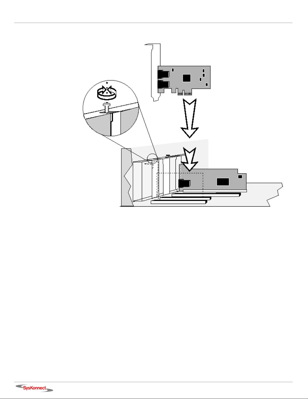
8. Insert the network adapter into the PCI Express resp. PCI/PCI-X slot as described in your computer manual (also see figure 1 “Insertion of the adapter into the computer”).
Make sure that the network adapter is correctly aligned with the PCI Express resp. PCI/PCI-X
slot on the motherboard.
9. Push the network adapter down vertically into the slot until it is firmly seated.
10. If available, tighten the locking screw on the fixing bracket until the adapter is firmly connected
to the computer cover (or to the attachment provided for expansion cards).
11. Replace the computer cover.
12. Replace and tighten all screws.
13. Reconnect the power supply.
Observe the safety instructions (see page 11).
SysKonnect SK-9Exx/9Sxx Gigabit Ethernet Server Adapters
14 1 Installation of the Network Adapter
Figure 1. Insertion of the adapter into the computer

2 Connection of the Network Adapter
This chapter describes the physical connection of the network adapter to the network. General instructions for driver installation are given in chapter 3 “Installation of the Driver Software”.
Transmission Distances
Depending on the physical media (cable) different distances can be reached for transmission with
the Gigabit Ethernet adapter:
Adapter Type Physical Media Maximum
Distance
1000Base-SX/LC
(850 nm)
1000Base-LX/LC
(1300 nm)
10/100/1000Base-T Category 5 unshielded twisted pair 100 m
1000Base-SX 50.0 µm multimode fiber-optic 550 m
1000Base-SX 62.5 µm multimode fiber-optic 275 m
1000Base-LX 10.0 µm monomode fiber-optic 5000 m
1000Base-LX 50.0 µm multimode fiber-optic 550 m
1000Base-LX 62.5 µm multimode fiber-optic 550 m
Connection to the Network
Observe the safety instructions given on page 11.
In order to connect the adapter to the data network, proceed as follows:
1. If necessary, configure the port on the switch to which the network adapter is to be connected
(also see the switch manual).
2. If possible, disconnect the switch and the computer from the power supply.
3. Remove the protective plug (if available) from the switch port, which is to be used.
4. At one end of the cable connect the LC duplex or RJ-45 connector to the port on the switch.
5. Remove the protective plug (if available) from the port on the network adapter (fiber-optic types
only).
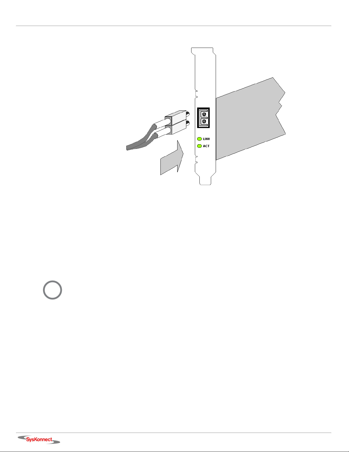
6. At the other end of the cable connect the connector to the port on the network adapter (see
figure 2 “Connection of fiber-optics cables/plugs”).
The port type (e.g. 1000Base-T) on the network adapter and that on the switch must be identical.
SysKonnect SK-9Exx/9Sxx Gigabit Ethernet Server Adapters
16 2 Connection of the Network Adapter
i
Figure 2. Connection of fiber-optics cables/plugs
7. Turn on the computer and the switch.
If no protocol driver has been loaded, go to chapter 3 “Installation of the Driver Software”.
After driver installation, return to step 8 of this list.
8. Check the link LED(s) to find out if the cable is connected correctly.
If the appropriate LED is on, the connection is established and active. Otherwise, you have to
check the network adapter more closely (for details, refer to chapter 6 “Testing the Network
Adapter” and chapter 7 “Troubleshooting”).
As soon as the connection to the network is established, the installation of the network adapter is
complete. Keep this manual with your computer manual for future reference.
The network adapter will not be fully operational until suitable drivers are loaded. See chapter 3
“Installation of the Driver Software” for details.

3 Installation of the Driver Software
The network drivers are located in the appropriate product directory on the enclosed installation CDROM and on the SysKonnect web site. The directory on the CD-ROM is organized into a number of
subdirectories for the various operating systems. The subdirectories contain the driver files and the
corresponding readme files. The readme files are available as ASCII text and in HTML format. Any
last-minute changes are documented in the “Release Notes” (if applicable) and on the driver site of
the SysKonnect web site.
To install a driver, follow the instructions given below and in the corresponding readme files.
The installation procedures described below are only valid for the SysKonnect SK-9Exx/9Sxx Giga-
i
bit Ethernet Server Adapter Family. For details on the installation of other SysKonnect adapters,
refer to the corresponding readme files.
There are two possibilities to view the readme files:
• with an internet browser
• with a text editor
Use an internet
browser
Use a text editor To view a text file, proceed as follows:
If you have an internet browser (or any other HTML viewer) installed on your computer, we recommend to use it for viewing the readme files.
To view the readme files with an internet browser, proceed as follows:
1. Insert the installation CD-ROM into your CD-ROM drive.
2. If the browser is not automatically launched, click
The start page of the installation CD-ROM is displayed.
3. Click D
A list showing all available network technologies is displayed.
4. Select your preferred network technology, e.g. G
A list showing all available network adapters belonging to this technology is displayed.
5. Select your network adapter, e.g. SK-9Exx.
A list showing all available drivers for this adapter is displayed.
6. Click the operating system for which you want to install the driver, e.g. W
The readme file is opened. Here, you will find detailed instructions on how to install the driver.
1. Insert the installation CD-ROM into your CD-ROM drive.
2. Go to the appropriate product directory, e.g. SK-9Exx.
A list of all available operating systems this network adapter supports is displayed.
3. Select the operating system for which you want to install the driver, e.g. W
4. Open the corresponding text file, e.g.
RIVERS.
START.HTM on the installation CD-ROM.
IGABIT ETHERNET.
INDOWS XP.
INDOWS > WIN2000.
SK50X86.TXT.
SysKonnect SK-9Exx/9Sxx Gigabit Ethernet Server Adapters
 Loading...